

Page 1
POWER SUPPLY & FRONT CONTROL PANEL
TRUECONTROL
550 WATT
Antec, Inc.
47900 Fremont Blvd.
Fremont, CA 94538
tel: 510-770-1200
fax: 510-770-1288
Antec Europe B.V.
Sydneystraat 33
3047 BP Rotterdam
The Netherlands
tel: +31 (10)462-2060
fax: +31 (10)437-1752
Technical Support:
US & Canada
1-800-22ANTEC
techsupport@antec-inc.com
Europe
+31 (10)462-2060
techsupport@antec-europe.nl
www.antec-inc.com
www.antec-europe.com
c Copyright 2002 Antec, Inc. All rights reserved.
Reproduction in whole or in part without written permission is prohibited. Printed in China.
Version 1.0 11/26/2002
User’s Manual
Page 2
TrueControl features individual, front-accessible +5V, +3.3V, +12V voltage
and fan controls. This allows user adjustment of individual voltages and fans
while the system is running. If you're monitoring system voltages or fans you
will be able to see the values change live via the hardware monitor software or
the motherboard BIOS. With this functionality you can stabilize a heavily loaded
system, even when overclocking. Additionally, this functionality allows adjustment of the minimum speed of the internal power supply fans and
case fans
connected to the Fan Only connectors.
Note: TrueControl consists of two parts: The TruePower power supply and the
control panel. This special power supply must be used with the panel to control
the voltages and the fan speed. The adjustment range is ±5% of the specified
voltages. You may use the power supply without connecting the panel however
doing so will automatically set the power supply to 95% of voltage spec. to
prevent unwanted higher output voltages.
TrueControl Connector: 6-pin white connector
(white cable) to connect TruePower power
supply to the Control Panel.
External Power Connector: TruePower features
a 4-pin external female connector (equivalent
to AMP1-480424-0 or Molex 8981-04) for
powering external peripherals that need either
+5V or +12V DC Power. Some examples of
compatible equipment are external drive
enclosures, water cooling and lighting systems, and a variety of automotive
products. (Some may require a cigarette lighter adapter, available separately.)
Installation:
Please install the TruePower power supply unit in your case as described in the
main TruePower manual that accompanied this product. Make sure the voltage
selector switch is set properly. Then install and connect the control panel as
described below.
Additional Installation for TrueControl:
1. Install the 5.25" front panel into your
case in an unused 5.25” drive bay
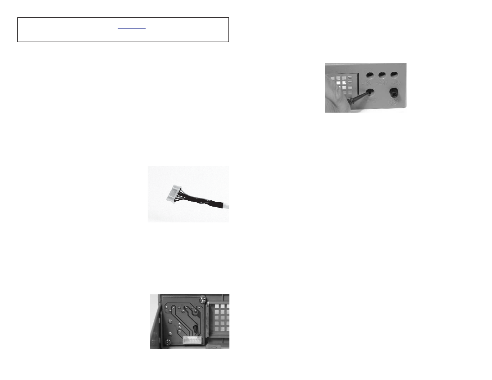
2. Connect the 6-pin white connector to the
connector behind the panel
(as shown on right).
The installation is completed.
Using TrueControl:
There are three voltage adjustment ports (marked with +12V, +3.3V and
+5V) and one fan adjustment knob for the user to adjust the voltages and
minimum fan speed. There is an adjustment tool comes with the panel to
adjust the voltages.
1. Boot up your system as normal.
2. Pull the adjustment tool out from the front panel.
3. Insert the tool into each adjustment port to adjust the voltages. The
default voltages are set at +12.0V, +3.3V and +5.0V
4. Turn the adjustment port clockwise to increase and counter clockwise
to decrease the voltage. The maximum voltage range you can adjust is
set at ±5%
To adjust the minimum fan speed, turn the knob clockwise to increase the
speed.
Note: This manual fan control does not override the built-in fan control
circuitry. Turning the knob only allows you to change the minimum fan
speed (default at about 1500 RPM) of the control circuitry. The upper
bound that you can set the minimum fan speed is up to 3500 RPM.
To calibrate your voltages outputs we recommend using a multi-meter to
verify the +12V and +5V voltages, as the motherboard BIOS may not
detect the voltages correctly. You cannot measure the+3.3V voltage
through the Molex 4-pin connector as described below since the connector
does not provide+3.3V current.
1. Set the measuring dial of your meter to VDC. Choose the maximum
measuring rage to+20VDC or higher.
2. To measure+12V: Use a 4-pin Molex connector from the power supply,
insert the positive pole (red) to a connector pin with a yellow wire and
insert the negative pole (black) to one of the connector pins with a
black wire. You should be able to read the voltage reading of +12V
output.
3. To measure+5V: Use a 4-pin Molex connector from the power supply,
insert the positive pole (red) to the connector pin with the red wire
and insert the negative pole (black) to one of the connector pins with
black wires. You should be able to read the voltage reading of +5V
output.
4. Adjust the voltage as desired on the TrueControl Control Panel with
the provided tool.
1
2
6-pin white connector
This manual is an addendum to the TruePower manual included with your
power supply. It is meant to be used in addition to that information
Connector behind panel
Adjustment tool
 Loading...