

Page 1
STUDIO SERIES
TAKE 4
4U RACKMOUNT CASE
User’s Manual
Page 2
2
At Antec, we continually refine and improve our products to ensure the highest quality. So it's
possible that your new case may differ slightly from the descriptions in this manual. This isn't
a problem; it's simply an improvement. As of the date of publication, all features, descriptions,
and illustrations in this manual are correct.
TAKE 4 — STUDIO SERIES USER'S MANUAL
CONNECTING THE POWER
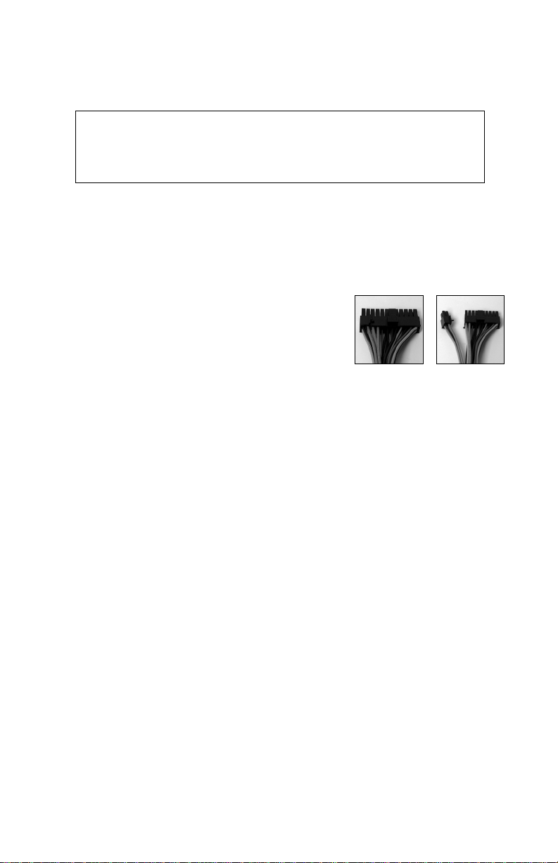
The power supply conforms to the latest ATX12V
Version 2.0 standard. It is also backwards-compatible
with previous ATX form factor power supplies. If your
motherboard has a 20-pin power receptacle, detach the
4-pin attachment on the 24-pin power connector (see
pictures 1 and 2). Before you connect the power supply
to any of your devices, please consult the appropriate
user manuals for your motherboard and other
peripherals.
[Applies only to models designed for sale in the European Union:
SmartPower 2 series power supply models designed for the EU include Power Factor Correction
(PFC) circuitry in accordance with European standard regulation code EN61000-3-2. By altering
the input current wave shape, PFC improves the power factor of the power supply. This results in
increased energy efficiency, reduced heat loss, prolonged life for power distribution and
consumption equipment, and improved output voltage stability.]
The power supply is also equipped with a 3-pin fan signal connector. Connect it to one of the
fan connectors on your motherboard. You may monitor the speed of the rear power supply fan
through your motherboard BIOS or through the monitoring software that's supplied with your
motherboard. Note: At low temperatures, the fan may run as slow as 950RPM. At these
speeds, some motherboards may not properly detect the fan speed and may generate false
warnings of fan failure. To ensure proper monitoring of the fan, please check your motherboard
manual.
POWER SUPPLY AIR DUCT
There is a special duct leading from the front of the chassis to the power supply. This design is
in place to keep the power supply quieter by providing the power supply with its own source of
air separate from the rest of the system. The power supply will draw air in from the front of
the case and exhaust it out the rear.
SIDE VENTS
There are vents on the left side of the rackmount. In an open rack environment, they increase
the airflow in the system by allowing more fresh air into the system when necessary. If you are
keeping your rackmount in a cabinet where environmental air circulation is not as good as open
Disclaimer
This manual is intended only as a guide for Antec's Computer Enclosures. For
more comprehensive instructions on installing your motherboard and peripherals,
please refer to the user's manuals which come with your components and drives.
Picture 1
Picture 2
For 24-pin
motherboards
For 20-pin
motherboards
Page 3

3
rack, please use the clear plastic film that came with the toolbox to cover
the ventilation (see picture 3). This can prevent hot air in the cabinet from
entering the system and causing heat related system problems.
CONNECTING THE USB PORTS
You will find two 4-pin connectors on cables attached to the front USB ports.
Connect the 4-pin connectors to your motherboard headers so that the USB Power pins match
the VCC pins on the connectors.
Note: Please check your motherboard manual for your USB header pin layout and make sure it
matches the attached table. If it does not match, please call Antec customer support at (800)
22ANTEC (North America) or at +31 (0) 10 462-2060 (Europe) to buy a USB adapter. This
adapter will allow you to connect the front USB to your motherboard on a pin-by-pin basis.
CONNECTING THE IEEE 1394 (FIREWIRE®, I.LINK®) PORT
You will find a single 10-pin connector on a cable attached to the front IEEE 1394 connection.
This is an Intel standard connector, which is keyed so that it can't be accidentally reversed as
long as it is connected to a proper Intel standard motherboard header. Connect the 10-pin
connector to your motherboard header so that the blocked pin fits over the missing header pin.
Note: Please check your motherboard manual for your IEEE 1394 header pin layout and make
sure it matches the attached table. If you intend to connect the front FireWire port to an IEEE
1394 add-on card that comes with an external-type IEEE1394 connector, please call Antec
customer support at (800) 22ANTEC (North America) or +31 (0) 10 462-2060 (Europe) to buy
an adapter. This adapter will allow you to connect the front IEEE 1394 port to the external-type
connector.
Pin
Signal Names Pin Signal Names
1
3
5
7
9
2
4
6
8
10
USB Power 1
Negative Signal 1
Positive Signal 1
Ground 1
Key (No Pin)
USB Power 2
Negative Signal 2
Positive Signal 2
Ground 2
Empty Pin
Intel Standard USB Header Pin Layout
1
2
9
10
Pin Signal Names Pin Signal Names
1
3
5
7
9
2
4
6
8
10
TPA+
Ground
TPB+
+12V (Fused)
Key (No Pin)
TPA–
Ground
TPB–
+12V (Fused)
Ground
Standard Pin Assignment for IEEE 1394 Connector
1
2
9
10
Picture 3
Page 4

4
3.5" DEVICE INSTALLATION
With the front bezel facing you, turn the latch and swing the front door. You can see there are
two 5.25" and two 3.5" external drive bays. Inside the case there are four 3.5" drive cages.
For external 3.5" devices:
1. Locate the external 3.5" drive bays. They are to the right of the 5.25" drive bays.
2. Unscrew the 4 small Phillips head screws located on the front panel around the drive cage.
3. Pull the cage and unscrew the drive bay covers.
4. Install your external 3.5" devices.
5. Reattach the cage and devices to the chassis.
Note: Don't take off the covers and plates for the drive bays that you are not using now.
For Internal devices:
6. Loosen the thumbscrews on each side of the drive bay, for the drive bay that you wish to
install a device.
7. Pull the drive tray forward all the way out of the chassis.
8. Mount your hard drive or other internal 3.5" device into the drive tray
through the bottom rubber grommets with the special screws provided
(see picture 4). Note: Don't over-tighten. Over-tightening the screws will
harm the vibration–and noise–reducing ability of the rubber grommets.
9. Slide the tray/device assembly back into the chassis and retighten the
thumbscrews.
10. Repeat the above as necessary.
11. Connect either a large 4-pin connector or SATA power connector from the power supply to
the male 4-pin connector or SATA connector on each of the other devices.
5.25" DEVICE INSTALLATION
1. Unscrew the two screws on the left side of chassis. Unscrew the four screws around the
front of the 5.25" drive bays (along the top and right sides of the cage).
2. Pull the cage towards the back of the case and then lift the cage out.
3. Unscrew the screws that attach the drive bay cover to the cage.
4. Install your 5.25" device.
5. Mount the other devices accordingly. Connect a large 4-pin connector from the power
supply to the male 4-pin connector on each of the devices.
COOLING SYSTEM
The TriCool fan:
The case includes one 120mm TriCool fan and one 92mm TriCool installed in the rear. These
fans have a three-speed switch that lets you choose between quiet, performance, or maximum
cooling. (See specifications below.) The fans are installed so that the air is blowing out of the
case. Connect a large 4-pin connector from the power supply to the male 4-pin connector on
the fan.
Note: The minimum voltage to start the fan is 5V. We recommend our users to set the fan
speed to High if you choose to connect the fan to a fan control device or to the Fan-Only
connector found on some of Antec's power supplies. A fan-controlled-device regulates the fan
speed by varying the voltage to it. The voltage may start as low as 4.5 V to 5V. Connecting a
TriCool set on Medium or Low to a fan-control device may result in the fan not being able to
start. The already lowered voltage from the fan control device will be further reduced by the
TriCool circuitry below 5V.
picture 4
Page 5

Specifications:
Size: 120 x 120 x 25.4 mm
Rated Voltage: DC 12V
Operating Voltage: 10.2V ~ 13.8V
Specifications:
Size: 92 x 92 x 25.4 mm
Rated Voltage: DC 12V
Operating Voltage: 10.2V ~ 13.8V
5
Speed Input
Current
Air Flow - at
rated voltage
zero static
pressure
(minimal
value)
Static
Pressure - at
rated voltage
at zero air
flow
Acoustical
Noise
Input
Power
High
2000RPM
0.24A (max.) 2.24 m³ / min
(79 CFM)
2.5mm-H2O
(0.10inch-H2O)
30 dBA 2.9 W
Medium
1600RPM
0.2A 1.59 m³ / min
(56 CFM)
1.5mm-H2O
(0.06inch-H2O)
28 dBA 2.4 W
Low
1200RPM
0.13A 1.1 m³ / min
(39 CFM)
0.9mm-H2O
(0.04inch-H2O)
25 dBA 1.6 W
Speed Input
Current
Air Flow - at
rated voltage
zero static
pressure
(minimal
value)
Static
Pressure - at
rated voltage
at zero air
flow
Acoustical
Noise
Input
Power
High
2000RPM
0.2A (max.) 1.08 m³ / min
(38 CFM)
1.0mm-H2O
(0.08inch-H2O)
27 dBA 2.4 W
Medium
1600RPM
0.1A 1.09 m³ / min
(28 CFM)
0.5mm-H2O
(0.02inch-H2O)
20.8 dBA 1.2 W
Low
1200RPM
0.08A 0.59 m³ / min
(21 CFM)
0.3mm-H2O
(0.01inch-H2O)
14.6 dBA 1.0 W
Page 6

Antec, Inc.
47900 Fremont Blvd.
Fremont, CA 94538
Tel: 510-770-1200
Fax: 510-770-1288
Antec Europe B.V.
Sydneystraat 33
3047 BP Rotterdam
The Netherlands
Tel: +31 (0) 10 462-2060
Fax: +31 (0) 10 437-1752
Technical Support
US & Canada
1-800-22ANTEC
customersupport@antec.com
Europe
+31 (0) 10 462-2060
europe.techsupport@antec.com
www.antec.com
© Copyright 2005 Antec, Inc. All rights reserved. All trademarks are the property of their respective owners.
Reproduction in whole or in part without written permission is prohibited. Printed in China.
Version 1.0.1 7/01/2005
 Loading...