

Page 1
E
ARTH
W
ATTS
P
OWER SUPPLY
350 G
REEN
U
SER’S
M
ANUAL
V1.0
Page 2
U
SER’S
E
ARTH
M
ANUAL
W
ATTS SERIES
EA-350 G
T
HE ENERGY-EFFICIENT
Get the power you need and the low electric bill you want with Antec’s EarthWatts 350 Green! One of
the most environmentally friendly power supplies on the planet, the EA-350 Green delivers 350 watts of
reliable, continuous power while meeting the Bronze level of performance from 80 PLUS®, the most
widely recognized independent standard in power supply efficiency.
S
TANDARDS AND FEATURES
The EA-350 Green PSU is compatible with ATX12V v2.32 and EPS12V v2.91 specifications. This PSU
features Universal Input, which automatically senses when you connect the power supply to any AC
power source between 100 ~ 240V, eliminating the need to set a voltage switch. The EA-350 Green also
features Active Power Factor Correction (Active PFC), which improves the power factor value of the PSU
by altering the input current wave shape, helping to transmit energy across the grid.
S
YSTEM PROTECTION
A variety of industrial-grade safety circuitry will help protect your computer: OCP (Over Current
Protection), OVP (Over Voltage Protection), SCP (Short Circuit Protection), OPP (Over Power Protection)
and OTP (Over Temperature Protection). Sometimes the PSU will “latch” into a protected shutdown state.
This means that you will need to power off the PSU and clear the fault before it will function again. There
are no user-replaceable fuses in your EA-350 Green.
REEN POWER SUPPLY
PSU
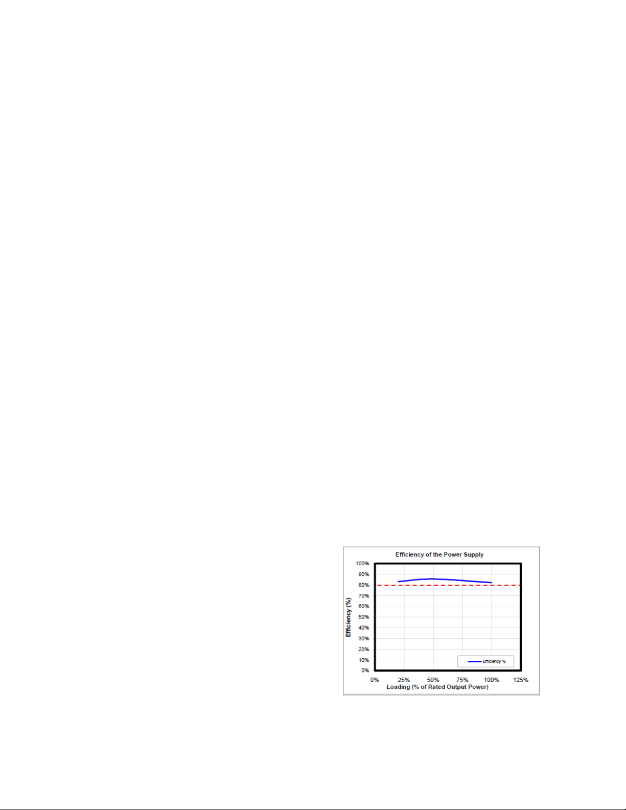
80 PLUS® B
80 PLUS® Bronze certification is among the highest
independent standards in power supply efficiency. This
allows the PSU to use less energy and generate less heat
so it stays cooler, runs more quietly, and lasts longer. The
EA-350 Green has been certified to be at least 82%
efficient at a wide range of operating loads and will
lower your operating costs while protecting the
environment.
RONZE CERTIFICATION
Source: 80 PLUS Verification and Testing Report
Page 3
D
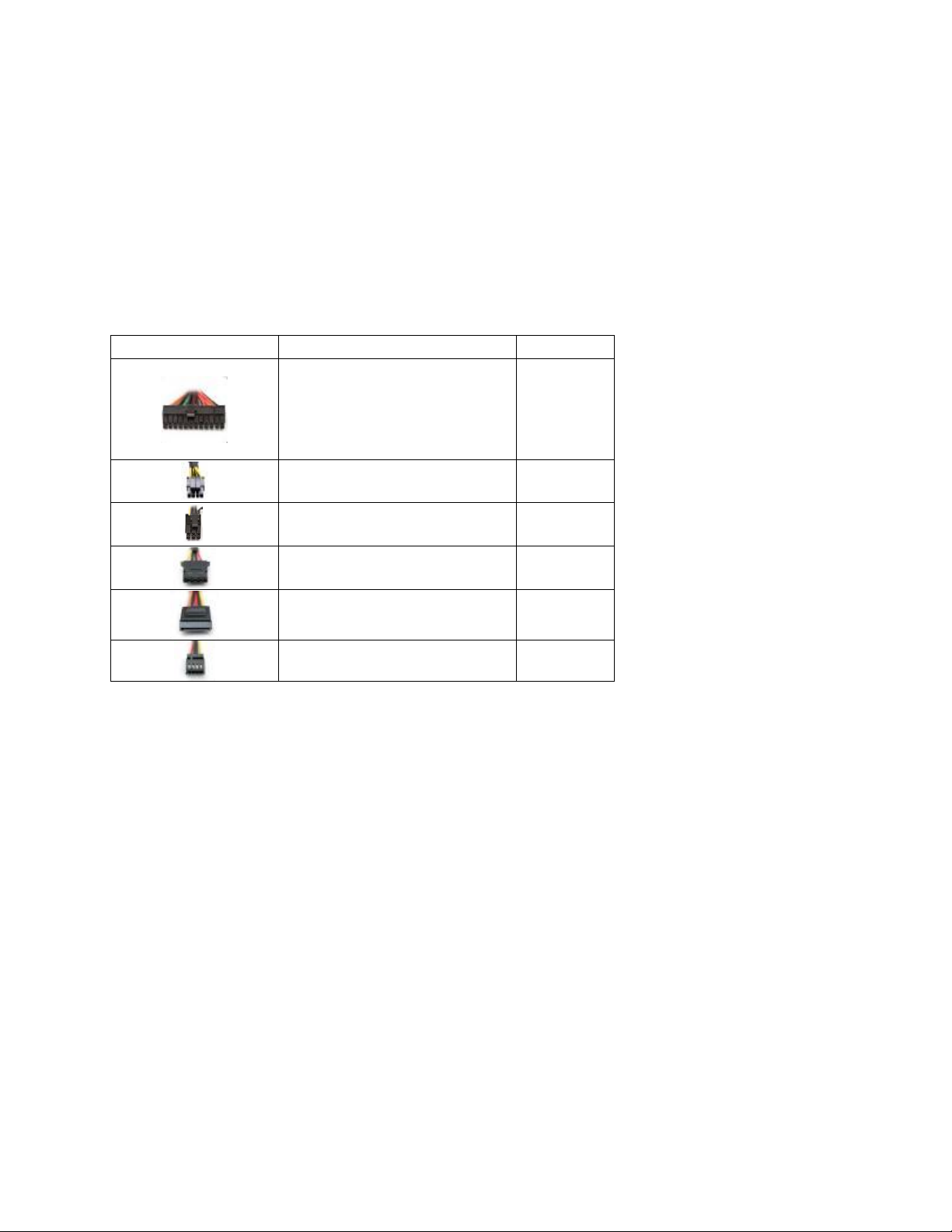
Power Connectors
Description
+12V Rail
UAL
+12 V
The EA-350 Green PSU uses dual +12 volt power rails. Different connectors are hooked up to separate
circuits to aid in the balanced distribution of power between devices in your computer. The +12V rails
have been assigned to different connectors, as shown in Table 2, to prevent voltage sags in one device
due to sudden demands for power by another device.
OLT RAIL DISTRIBUTION
T
ABLE 2: POWER CONNECTORS AND RAIL ASSIGNMENTS
24(20+4)-pin main connector
1
1 x 8(4+4)-pin ATX12V / EPS12V
P
OWER OUTPUT
The EA-350 Green PSU distributes a varying maximum number of amps on each rail. To see the output
capacity and regulation for each different voltage, see Table 3.
1 x 6-pin PCI-E
3 x Molex
3 x SATA
Floppy
2
1
1
1
1
Page 4

T
ABLE 3: OUTPUT CAPACITY AND REGULATION
Output
Voltage
+3.3V 16A ±5% 40mV
+5V 16A ±5% 40mV
+12V1 18A ±5% 80mV
+12V2 18A ±5% 80mV
–12V 0.3A ±10% 120mV
+5Vsb 2.5A ±5% 40mV
The continuous maximum total output power shall not exceed 350W.
+12V1 and +12V2 DC maximum output power shall not exceed 330W.
+3.3V and +5V DC maximum combined output power shall not exceed 105W.
Load Max. Regulation Ripple & Noise
I
NSTALLATION
1. Install the EA-350 Green PSU into your case with the four screws provided.
:
Page 5

2. Connect the 24-pin main power connector to your motherboard. If your motherboard
uses a 20-pin connector, detach the 4-pin attachment on the 24-pin connector.
Note: The detachable 4-pin section cannot be used in place of a 4-pin +12V connector.
3. Connect the 8-pin or 4-pin ATX12V connector for the CPU to the appropriate connector
on your motherboard. If your motherboard has an 8-pin socket with a cover on some of
the openings, we recommend that you remove the cover and use the 8-pin connector.
Note: Please also refer to your motherboard user’s manual for any special instructions.
4. Connect the PCI-E connector(s) to your graphics card(s), if applicable.
5. Connect all Molex/SATA connector(s) to your hard drives, optical drives
(CD/DVD/BluRay™) and other accessories. Please note that some devices will use either
the older 4-pin Molex connectors, while others will use the newer 5-pin SATA connector.
4-pin Molex connectors have two black wires, a yellow, and a red. The SATA connector
has an additional orange power wire.
Page 6

6. Connect your floppy drive (if present) using the supplied FDD connector shown in Table
2.
7. Connect an AC power cord to the power supply AC inlet. Turn the switch to the “|”
position after you have connected all the devices and are ready to turn on your
computer.
Page 7

Antec, Inc.
47900 Fremont Blvd.
Fremont, CA 94538
tel: 510-770-1200
fax: 510-770-1288
Antec Europe B.V.
Stuttgartstraat 12
3047 A Rotterdam
Netherlands
tel: +31 (0) 10 462-2060
fax: +31 (0) 10 437-1752
Technical Support:
US & Canada
1-800-22ANTEC
customersupport@antec.com
Europe
+49-40-226-139-2
europe.techsupport@antec.com
www.antec.com
© 2011 Antec Inc. All rights reserved.
Specifications are subject to change without prior notice.
Actual product and accessories may differ from illustrations.
Omissions and printing errors excepted.
Content of delivery might differ in different countries or areas.
Some trademarks may be claimed as the property of others.
 Loading...