

Page 1
The World’s Leading Cable and Antenna System Analyzer
Site Master
™
Transmission Line and Antenna Analyzer
2 MHz - 20 GHz
Page 2
THE LEADING CABLE AND ANTENNA ANALYZER FOR
WIRELESS PROFESSIONALS
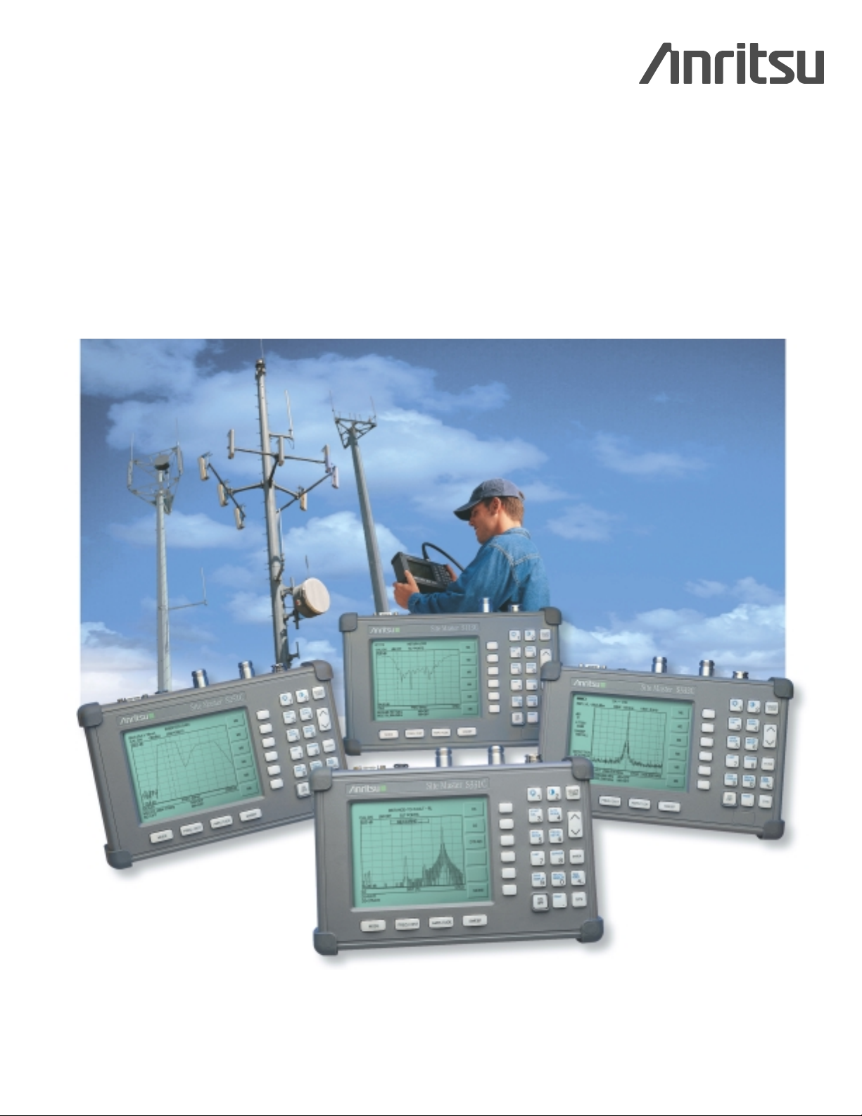
Anritsu’s Site Master cable and antenna analyzer is
the preferred choice of service providers, network
operators and contractors worldwide who install,
deploy, maintain and troubleshoot wireless communication systems.
Featuring an advanced synthesizer-based, handheld,
battery-operated design, Site Master helps wireless
field engineers and technicians detect cable feedline
and antenna system problems before they become
costly, time-consuming system failures. Superior
immunity to ambient RF levels, and excellent
directivity and source match ensure accurate and
repeatable measurements.
Easy-to-Use
Site Master’s menu driven interface requires little
training and simplifies the field engineers and technicians
task of deployment, site-to-site maintenance and
troubleshooting by identifying, recording and solving
problems without sacrificing measurement accuracy.
• Store ten test setups for fast repeatable testing.
• Store up to 200 measurement traces in nonvolatile
memory.
• Quickly select cable type and test parameters without
setup error.
• Multilingual user interface features on screen menus
and messages in 6-different languages.
• InstaCal
™
calibration module simplifies Site Master
calibration.
Accurate, Repeatable Measurements
Utilizing vector error correction, Site Master delivers
accurate, reliable and repeatable Return Loss/SWR and
Fault Location measurements.Site Master’s high immunity
to interference allows users to conduct measurements of an
active site without the loss of accuracy.
• Locate long range problems with 517 data points.
• Superior immunity to on-channel interference for testing at
co-located antenna sites.
• Large, high-resolution display allows for easy viewing and
trace interpretation under a variety of conditions.
• Full range of marker and limit functions facilitate quick,
comprehensive measurements.
Rugged and Reliable
Designed specifically for field environments, Site Master
withstands harsh environments and rough handling. Built-in
energy conservation combined with a rechargeable battery
pack allows users to extend battery life beyond an eight hour
work day. Site Master can also be operated from a 12.5 Vdc
source such as an AC-DC adapter or automotive cigarette
lighter adapter, which also simultaneously charges the battery.
Powerful Data Analysis Software
Powerful data analysis software comes with every Site Master
unit, providing users with an easy method of analyzing system
performance, trends and problems in addition to professional
report generation.
• Site Master PC software is Windows 95/98/NT4/2000/ME/XP
workstation compatible and supports long alpha-numeric
file names for descriptive data labeling.
• Store an unlimited number of data traces for comparison to
historical performance.
• Quickly and easily download data traces from the Site
Master to a PC database with a single menu selection.
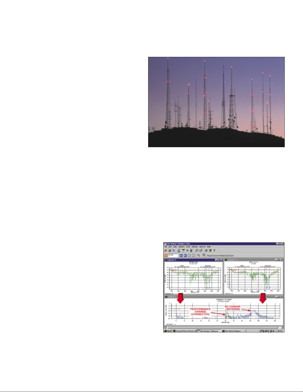
Site Master Software Tools provides a data base to compare maintenance
interval performance to site commissioning data. The Distance-To-Fault
display pinpoints problem areas before they degenerate into failures. In the
graph to the left, a loosened connector changes the return loss characteristic from 38 dB to 33 dB (< 0.05 SWR increase). Although the above cable
sweeps appear to meet specifications, they are indicative of a probable
loose weather seal which will eventually allow water intrusion.
Page 3
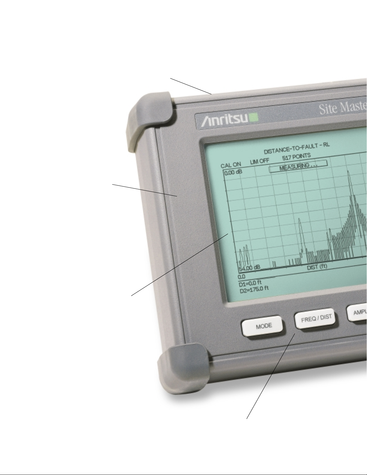
The Picture is Actual Size . . .
RS-232 Interface
Download stored data to a personal computer
(PC) or a printer via a serial cable for further
analysis. Use your notebook
computer to automatically
control and collect data in
the field. Use a modem
for remote operation.
Rugged Chassis Design
Ruggedized, lightweight,
high-impact housing ideally
suited for handheld operation
and field environments.A
softcase is provided for easy
carrying and additional
environmental protection.
Large High Resolution Display
High resolution (640x480)
display featuring contrast and
back-lighting capability. Easy
viewing under a variety of
lighting conditions.
Function Keys
Four dedicated function keys
simplify measurement tasks.
Unit Measurements
Metric: 25.4 x 17.8 x 6.10 cm
Inches: 10 x 7 x 2.4 in
2
Page 4
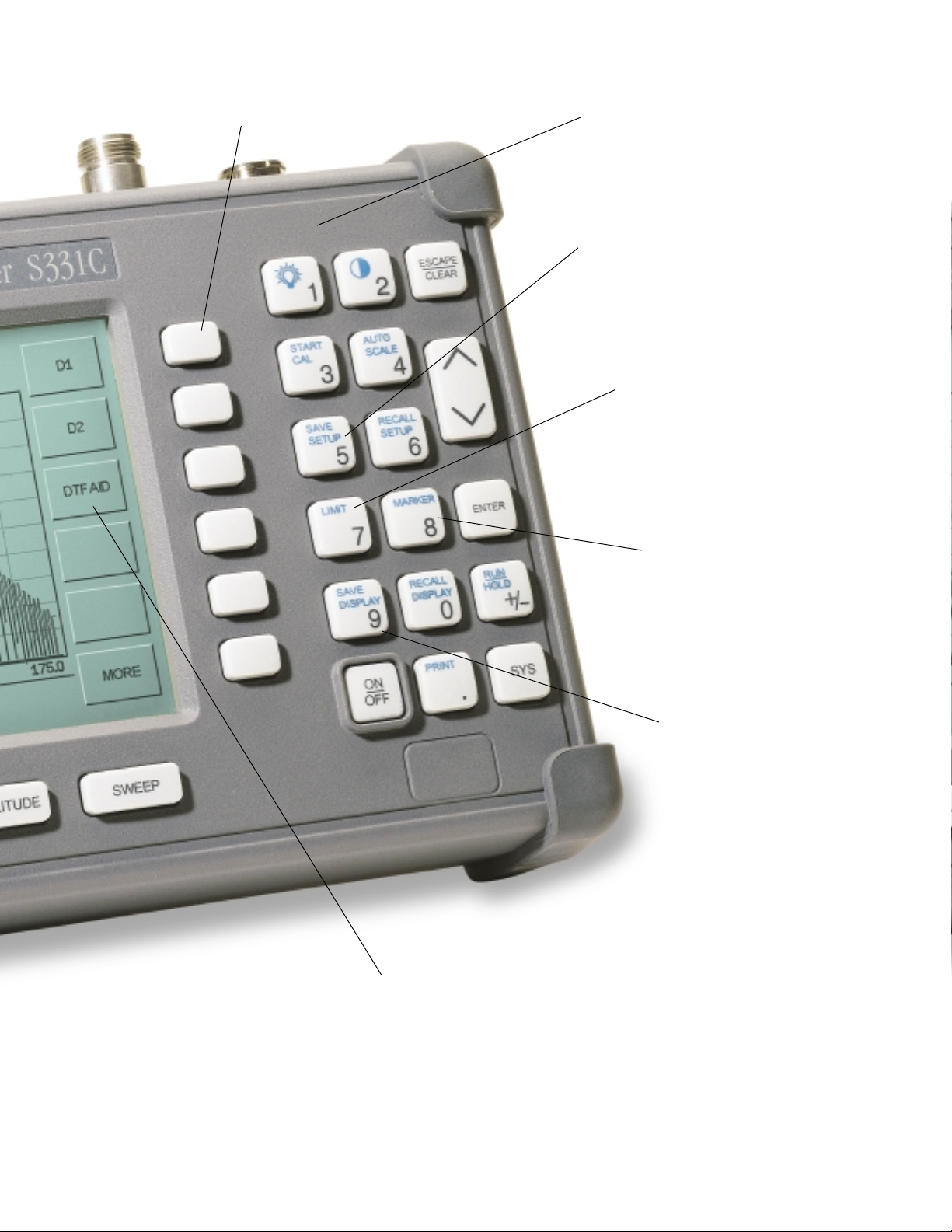
The Benefits are Much Larger
Limit Line
Create simple, quick
pass/fail measurements
Full Range of Marker Capabilities
Faster, more comprehensive
measurements
Soft Keys
Intuitive soft key menu and
user interface
Save Setup
Ten memory locations for calibration
profiles or test set-ups. Enables fast
repeatable testing.
Multilingual User Interface
Multi-language user interface
features on-screen menus and
messages in 6-different languages.
Save Display
Up to 200 memory locations
for measurement data.
Alphanumeric data labeling
allows descriptive naming of
measurement data; Automatic
time and date stamp simplifies
data management.
Cable List
Quickly select cable type and test parameters without set-up
errors. Site Master features pop-up menus that contain over 75
of the most popular cables used within the industry, 3 frequency
band presets.
Page 5
EASY-TO-USE, REDUCES ERROR, INCREASES SYSTEM UPTIME
Cost Savings and Quality Improvement
Wireless market competition requires operators to reduce
per site maintenance expense.Site Master’s Frequency
Domain Reflectometry (FDR) techniques break away from
the traditional fix-after-failure maintenance process by finding
small, hard to identify problems before major failures occur.
Site Master’s approach to preventive maintenance pays for
itself quickly. A poorly installed cable, connector, or connector weather seal will degrade system performance and, if
undetected, will eventually damage expensive coaxial cable.
Only Site Master has the sensitivity to identify cable, connector and antenna related problems before system performance is compromised.
FDR T echnique
Frequency Domain Reflectometry, (FDR), and Time Domain
Reflectometry, (TDR), have similar acronyms, and both
techniques are used to test transmission lines. But, that’s
where the similarities end.TDRs are not sensitive to RF
problems: the TDR stimulus is a DC pulse, not RF.Thus, TDRs
are unable to detect system faults that often lead to system
failures.Additionally, FDR techniques save costly, timeconsuming trouble shooting efforts by testing cable feedline
and antenna systems at their proper operating frequency.
Deficient connectors, lightning arrestors, cables, jumpers, or
antennas are replaced before call quality is compromised.
Quick, Simple Measurements
Site Master performs various RF measurements aimed at
simplifying cable feedline and antenna system analysis:
Return Loss, SWR, Cable Loss and Distance-to-Fault (DTF).
A single softkey selection on the main menu activates the
desired measurement mode.
Return Loss, SWR
Return Loss and/or
SWR "system"
measurements ensure
conformance to system
performance engineering specifications.
Measurement easily
toggles between either
one of the two modes
and can be performed
without climbing the
tower.
Cable Loss
Cable Loss measurements measure the
level of insertion loss
within the cable
feedline system.
Insertion loss can be
verified prior to
deployment, when
you have access to
both ends of the
cable, or on installed
cables without
access to the opposite end.
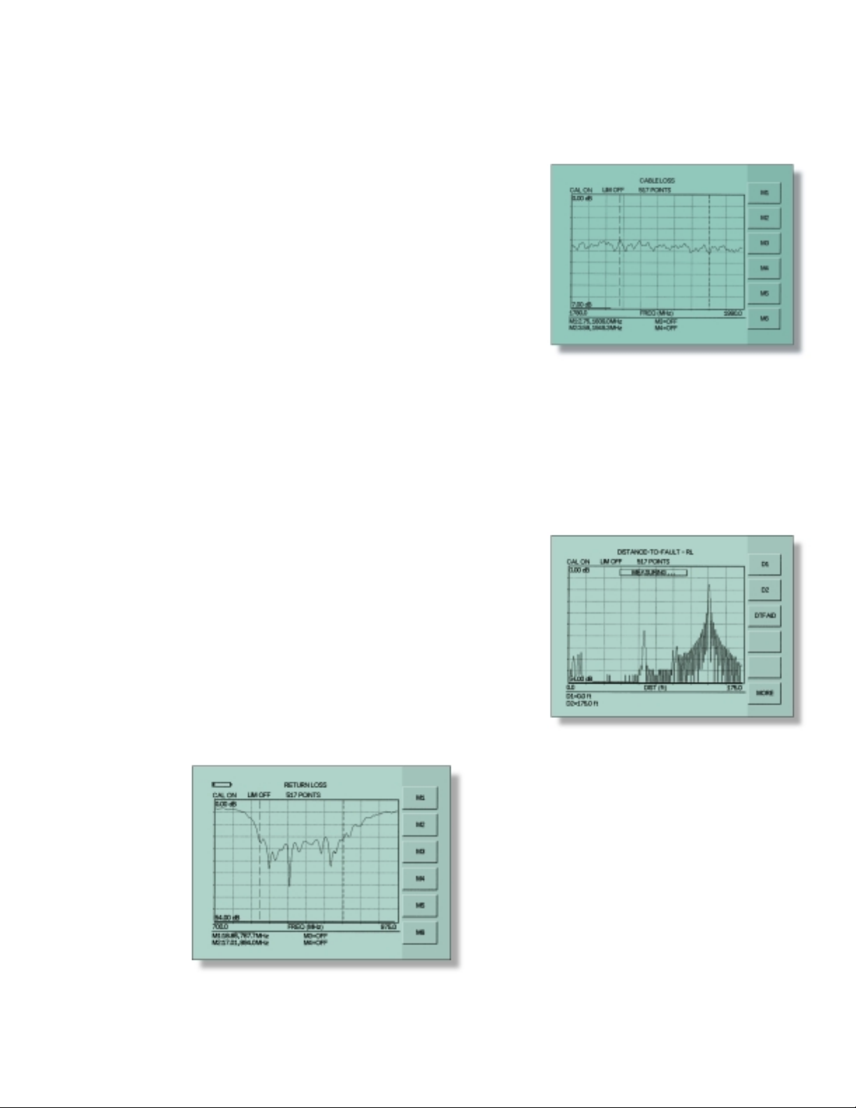
Distance-to-Fault
Although a Return Loss test can tell users the magnitude of
signal reflections, it can not tell the precise location of a fault
within the feedline system.Distance-To-Fault measurements
provide the clearest indication of trouble areas (screen display
below) as it tells us both the magnitude of signal reflection
and the location of the signal anomaly.
Distance-To-Fault
measurement
capability is built into
all Site Master
Models as a standard
feature.Return Loss
(SWR) measurement
data is processed
using Fast Fourier
Transform and the
resulting data
indicates Return
Loss (SWR) versus
distance.
Distance-To-Fault pinpoints the location and
reflection amplitude of transmission line
components.
3
Page 6

SITE MASTER S251C FOR 2-PORT/TOWER TOP APPLICATIONS
4
Performance enhancing design trends such as high
sector-to-sector isolation, tower-mounted amplifiers and
duplexed antennas add new complexities to site installation,
deployment, maintenance and troubleshooting.To help
simplify performance verification for these systems, a second
test port for isolation, gain and insertion loss measurements
is required. Addressing this need, the Site Master S251C
features a second test-port for testing sector-to-sector
isolation, tower-mounted amplifiers and duplexed antennas.
Gain
The Site Master S251C, features a selectable output power
at +6 dBm or –30 dBm and an optional, built-in Bias Tee, to
enable two-port insertion gain measurement of Tower
Mounted Amplifiers (TMA) without the need of an external
supply through
the PDU (Power
Distribution Unit)
and an external
attenuator.This
greatly simplifies
the technician’s
task of verifying
amplifier and
system performance during installation or periodic
maintenance and troubleshooting intervals. Site Master’s
industry leading high RF interference immunity allows test
signal injection
between antennas
with a minimum of
interference induced
distortion and is
designed to perform
both installation and
maintenance tests
from ground level.
Isolation
Improving isolation between antenna sectors can reduce
cell-to-cell RF Interference and improve system coverage
and capacity. To
address this measurement requirement,
the Site Master
S251C features high
dynamic range,
which ensures that
antenna isolation is
accurately measured
during deployment
and during periodic
maintenance
intervals – including the extremely high >90 dB isolation
ranges required at RF-RF repeater sites.
Measuring antenna isolation during periodic maintenance
intervals conveniently verifies antenna position after harsh
weather.If the antenna has been moved from the installed
mounting angle, the change in side lobe and back lobe
coupling magnitudes between the antennas causes a clear
performance change.Tx-Rx isolation of duplexers and filters
is easily tested with Site Master’s >90 dB dynamic range.
Filters are easily aligned and verified to manufacturer’s
specifications.
Site Master’s high dynamic range enables
LNA measurements at ground level.
Accurately measure antenna isolation with
Site Master’s high dynamic range.
Amplifier Gain Test Measurement.
2-PORT
SITE
MASTER
RF IN
RF OUT
LNA
2-PORT
SITE
MASTER
RF IN
RF OUT
ANTENNA
ISOLATION
ANTENNA
DUPLEXER
2-PORT
SITE
MASTER
RF IN
RF OUT
LNA
LNA
ANTENNA
ANTENNA
TEST
SIGNAL
Tx
Rx
Page 7

5
SITE MASTER S800 SERIES FOR MICROWAVE APPLICATIONS
The Site Master S800 series, is the most accurate and
convenient tool available for field installation, verification,
troubleshooting and repair of microwave communication
systems. Difficult test specifications are easy to verify.The
S800 series improves quality and reduces maintenance
expenses by providing vector corrected calibration and a
convenient user interface.These new microwave Site Master
models test both waveguide and coaxial cables more
conveniently than laboratory-sized scalar analyzers or
microwave test sets.
Vector Error Correction
Vector error correction within the S800 series improves the
quality and convenience of measurements compared to
traditional scalar techniques. Accuracy and repeatability
account for errors such as test port match and source match
errors.Vector correction allows the test port to achieve the
highest commercial directivity to 50 dB (frequency range
dependent) using relatively small calibration components.
Waveguide Dispersion
Vector error correction also improves the quality of DistanceTo-Fault data. Not only is the reflection magnitude more
accurate, but the waveguide dispersion correction for fault
location (different frequencies propagate at different speeds)
is more accurate and
repeatable.The postvector corrected data
accounts for the nondispersive length of
coaxial cable preceding the input of the
waveguide under test.
Unlike scalar-based
systems, the Site
Master S800 Series
do not suffer reflection magnitude errors
(a failure looks better
than actual) and
length inaccuracies in
proportion to the
relative lengths of the
coaxial input cable and
waveguide under test.
Vector Correction Avoids Bulky Waveguide Coupler
Waveguide Calibration
The test port interface to the waveguide under test is a small
coaxial-to-waveguide adapter rather than a bulky precision
coupler.
The calibration components include two offset shorts,1/8 and
3/8 wavelength, and a precision load.The two offset shor ts
eliminate reference error suffered by scalar systems when
only a single waveguide short is used to determine the 0.0 dB
reflection reference level. Site Master’s innovative flange
design mates to square, rectangular or circular flanges. For a
given waveguide size, only one calibration set is required.
Site Master’s waveguide calibration components are built
with precision alignment pins that mate the companion
coaxial to waveguide adapters. As a result, proper alignment
of waveguide is fast and convenient.
REFERENCE PLANE
CALIBRATION COMPONENTS
TEST
PORT
CABLE
SITE
MASTER
COAX-TO-WAVEGUIDE
ADAPTER
1/8 λ WAVEGUIDE SHORT
3/8 λ WAVEGUIDE SHORT
WAVEGUIDE LOAD
PRESSURIZED WAVEGUIDE
FLEX WAVEGUIDE
JUMPER
TRANSMISSION LINE
FLEX WAVEGUIDE
JUMPER
ANTENNA
Page 8

6
SITE MASTER WITH INTEGRATED SPECTRUM ANALYSIS
CAPABILITY
Site Master models S114C and S332C add spectrum
analysis capability to the standard cable and antenna
analyzer function of Site Master.Now technicians and field
engineers can identify and solve RF system problems like
coverage, interference, antenna alignment, and in-band
interference from unwanted sources among other path
related signal problems in addition to cable and antenna
analysis measurements.
• Wide dynamic range, featuring –95 dBm DANL
• Increased video bandwidth selection
• Quick zoom-in, zoom-out display
• Manual and automatic coupling/decoupling of span, RBW
and VBW functions
• Manual and automatic attenuator control
• Field strength measurement
• Occupied bandwidth measurement
• Channel power measurement
• Adjacent channel power measurement
Field Maintenance
Ideal for field maintenance, the Site Master S114C, S332C
simplifies the task of going site-to-site identifying, recording
and solving problems.Moreover, these tasks can be completed
in a fraction of the time required to haul bench-top or other
"portable" equipment to the field. Featuring a synthesizerbased design and built-in measurement functions allow for
easy verification of system performance. User-frequency
menu functions, high sensitivity, and excellent repeatability
pinpoint the smallest RF signal levels.Harmonics, Occupied
Bandwidth, Channel Power and potential interference can be
measured before small problems grow into big, costly, timeconsuming headaches and unwanted site down time.
RF
Interference
Identifying the RF
Interference
problems can be
very difficult. Site
Master’s low noise
floor make small
signals easily
detectable.
Channel
Power
Performing channel power measurements help to determine if
a transmitter is operating in compliance with system specifications by measuring the power and power spectral density in a
given channel bandwidth.Another common transmitter measurement is adjacent channel leakage power that measures the
amount (or ratio) of power leakage into adjacent radio channels.
Signal Mapping
Ideal for site surveys and other signal mapping
applications, the Site Master Models S114C
and S332C can optimize placement of antennas
and access points in a WLAN or WPBX network.
Identification of potential in-band interference
as well as transmitted signal quality can be easily
performed as the installer moves about the
installation site.
Page 9

Although Site Master features built-in
analytical and reporting functions, users
can also download measurement data to
a PC for additional analysis or report
generation. Site Master’s user friendly
Software Tools is a Windows
®
program
designed specifically for cable and antenna
analysis and will run on any computer with
Windows 95/98/NT4/2000/ME/XP.Test data
can be analyzed and compared to historical
performance.
• Up to 200 Site Master trace memory
locations can be down loaded with a
single menu selection.
• Build historical records with an unlimited
number of traces in one document.
• Familiar Windows 95/98/NT4/2000/ME/XP
interface simplifies data analysis and
report generation.
• Intelligent drag-and drop automatically
converts traces to a common scale and
speeds fault identification.
• Supports long file names for easy
measurement data identification.
• Smith Chart function displays S11 vector
magnitude and phase data, allowing
system components to be impedance
matched for optimum performance.
7
PC SOFTWARE TOOLS FOR PROFESSIONAL ANALYSIS AND
REPORT GENERATION
Analysis displays include MilliRho (mρ) reflection coefficient data
format or S11Smith Chart. The on-screen measurement calculator now
also includes Transmitted power percentage. Print outs support multiple
plots per page.
Create new database files or add to an existing database. Site Master
Software Tools quickly stores antenna system test data to a single
relational database file.
Create professional reports with Site Master software tools. The above plot illustrates connector
related problems that can be easily understood.
Page 10

Anritsu
Site Master
Models
S113C S114C S331C S332C S251C S810A S818A S820A
Frequency
Range (MHz) 2-1600 2-1600 25-4000 25-4000 625-2500 3.3-10.5 GHz 3.3-18 GHz 3.3-20 GHz
Resolution kHz 10 10 100 100 10 1 MHz 1 MHz 1 MHz
Markers 6666 6 4 4 4
Display
Point (Max.) 517 517 517 517 517 130 130 130
Interference
Immunity (dBm)
On-Frequency
(1)
+10 +10 –5 –5 +10 RF Out; +30 dBc RF In
(3)
–10 –10 –10
On-Channel
(2)
+17 +17 +17 +17 +17 N/A N/A N/A
Calibration:
Instrument
Configurations 10 10 10 10 10 6 6 6
Data Storage
Reporting:
Alpha Numeric Yes Yes Yes Ye s Ye s No No No
Time/Date Stamp Yes Yes Ye s Yes Yes No N o N o
Numeric Yes Yes Yes Yes Yes Yes Yes Ye s
Memory
Locations (Max.) 200 200 200 200 200 70 70 70
Measurement
Characteristics
(4)
Return Loss ✓✓✓✓ ✓ ✓ ✓ ✓
SWR ✓✓✓✓ ✓ ✓ ✓ ✓
Cable Loss ✓✓✓✓ ✓ ✓ ✓ ✓
DTF ✓✓✓✓ ✓ ✓ ✓ ✓
Insertion Gain ✓
Isolation ✓
Insertion Loss ✓
Spectrum Analysis N/A 0.1-1600 MHz N/A 0.1-3000 MHz N/A N/A N/A N/A
8
NEVER BEFORE HAS ONE ANALYZER FAMILY SOLVED SO
MANY ANTENNA SYSTEM PROBLEMS
Whether your system is cellular, PCS/DCS, 3G, paging, data, SMR, WLAN/WPBX or any other type of wireless service covering
the 2 MHz to 20 GHz frequency range, Site Master by Anritsu offers a cable and antenna analyzer solution for you.
1. On-Frequency Interference Immunity is specified to within ±10 kHz of the carrier frequency.
2. On-Channel Interference Immunity is specified at >1 MHz of the carrier frequency.
3. In most field applications, Immunity is typically better because interferring signals are modulated and varying in frequency rather than CW. Measurements were
made in CW mode by injecting a signal into the Site Master through a coupler.
4. All Anritsu Site Master models include Return Loss, SWR, Cable Loss, and Distance-To-Fault.
Page 11

9
SITE MASTER OPTIONS AND ACCESSORIES
RF Power Monitor (Option 5)
The optional RF Power Monitor features precision, high return loss
(low SWR) detectors.This excellent impedance match significantly
reduces the largest component of power measurement error,
mismatch uncertainty.Display formats include absolute power (dBm
or Watts) and relative power (dBr or %). Built-in Auto-Averaging
automatically reduces the effects of noise while zeroing control allows
optimum measurement accuracy at low power levels.
InstaCal™Calibration Module*
The InstaCal calibration module is available for all one-por t
Site Master models (S113C, S114C, S331C and S332C).
With InstaCal, users can cut the time required to calibrate
the Site Master by as much as 50%. Moreover, InstaCal
reduces the potential for calibration error. With discrete
calibration components users are required to connect,
disconnect, and reconnect the various calibration
components during the calibration process, which greatly
increases the potential for calibration/measurement error.
With InstaCal, users are only required to connect the
InstaCal calibration module once – the calibration process
sequences automatically, ensur ing an accurate calibration
of the Site Master.The benefit is calibrated measurements in
much less time.
Microwave
Accessories
Calibration components
mate directly to a variety of
commercial and standard
military flanges – eliminating
the necessity of bulky,
precision waveguide
couplers. A few examples
of waveguide adapters are
35UA187N, 35UM40N, and
35UM58.
Bias Tee (Option 10A-S251C Only)
The optional bias tee is integrated inside the Site Master and
is designed for applications where both DC and RF signals
must be applied to a device under test, such as a tower
mounted amplifier (TMA). DC voltages of up to 15 volts at
0.24 amps may be applied to test devices with negligible
effect on RF performance as an RF input DC block isolates
the input port from the applied bias voltage.
InstaCal™Module ICN50
*The InstaCal™Calibration Module exhibits
slightly degraded directivity performance
compared to precision loads. Users having
applications that require DTF-RL measurements > 38 dBmay want to consider
using precision load calibration components
in place of the InstaCal calibration module for
greater measurement accuracy.
InstaCal™Module ICN50
Page 12

Precision Waveguide Calibration Components
Part Number Description Freq Range Waveguide Type Compatible Flanges
xxUM40 1/8, 3/8 λ Offset Short and Load, Metric 3.30 to 4.90 GHz WR229, WG11A PDR40
xxUM48 1/8, 3/8 λ Offset Short and Load, Metric 3.95 to 5.85 GHz WR187, WG12 CAR48, PAR48, UAR48, PDR48
xxUM58 1/8, 3/8 λ Offset Short and Load, Metric 4.90 to 7.05 GHz WR159, WG13 CAR58, PAR58, UAR58, PDR58
xxUM70 1/8, 3/8 λ Offset Short and Load, Metric 5.85 to 8.20 GHz WR137, WG14 CAR70, PAR70, UAR 70, PDR70
xxUM84 1/8, 3/8 λ Offset Short and Load, Metric 7.05 to 10.00 GHz WR112, WG15 CBR84, UBR84, PBR84, PDR84
xxUM100 1/8, 3/8 λ Offset Shor t and Load, Metr ic 8.20 to 12.40 GHz WR90, WG16 CBR100, UBR100, PBR100, PDR100
xxUM120 1/8, 3/8 λ Offset Shor t and Load, Metr ic 10.00 to 15.00 GHz WR75, WG17 CBR120, UBR120, PBR120, PDR120
xxUM140 1/8, 3/8 λ Offset Shor t and Load, Metr ic 12.40 to 18.00 GHz WR62, WG18 CBR140, UBR140, PBR140, PDR140
xxUM220 1/8, 3/8 λ Offset Shor t and Load, Metr ic 17.00 to 26.50 GHz WR42, WG20 CBR220, UBR220, PBR220, PDR220
xxUA229 1/8, 3/8 λ Offset Short and Load, US 3.30 to 4.90 GHz WR229, WG11A CPR229F, CPR229G, UG-1350/U, UG-1351/U,
UG-1726/U, UG-1727/U
xxUA187 1/8, 3/8 λ Offset Short and Load, US 3.95 to 5.85 GHz WR187, WG12 CPR187F, CPR187G, UG-1352/U, UG-1353/U,
UG-1728/U, UG-1729/U, UG-148/U, UG-149A/U
xxUA159 1/8, 3/8 λ Offset Short and Load, US 4.90 to 7.05 GHz WR159, WG13 CPR159F, CPR159G, UG-1354/U, UG-1355/U,
UG-1730/U, UG-1731/U
xxUA137 1/8, 3/8 λ Offset Short and Load, US 5.85 to 8.20 GHz WR137, WG14 CPR137F, CPR137G, UG-1356/U, UG-1357/U,
UG-1732/U, UG-1733/U, UG-343B/U, UG-344/U,
UG-440B/U, UG-441/U
xxUA112 1/8, 3/8 λ Offset Short and Load, US 7.05 to 10.00 GHz WR112, WG15 CPR112F, CPR112G, UG-1358/U, UG-1359/U,
UG-1734/U, UG-1735/U, UG-52B/U, UG-51/U,
UG-137B/U, UG-138/U
xxUA90 1/8, 3/8 λ Offset Short and Load, US 8.20 to 12.40 GHz WR90, WG16 CPR90F, CPR90G, UG-1360/U, UG-1361/U,
UG-1736/U, UG-1737/U, UG-40B/U, UG-39/U,
UG-135/U, UG-136B/U
xxUA75 1/8, 3/8 λ Offset Short and Load, US 10.00 to 15.00 GHz WR75, WG17 WR75
xxUA62 1/8, 3/8 λ Offset Short and Load, US 12.40 to 18.00 GHz WR62, WG18 UG-541A/U, UG-419/U, UG-1665/U, UG1666/U
xxUA42 1/8, 3/8 λ Offset Short and Load, US 17.00 to 26.50 GHz WR42, WG20 UG-596A/U, UG-595/U, UG-597/U, UG-598A/U
xxCMR229 1/8, 3/8 λ Offset Short and Load, CMR 3.30 to 4.90 GHz WR229, WG11A CMR229
xxCMR187 1/8, 3/8 λ Offset Short and Load, CMR 3.95 to 5.85 GHz WR187, WG12 CMR187, UG1475/U, UG1480/U
xxCMR159 1/8, 3/8 λ Offset Short and Load, CMR 4.90 to 7.05 GHz WR159, WG13 CMR159
xxCMR137 1/8, 3/8 λ Offset Short and Load, CMR 5.85 to 8.20 GHz WR137, WG14 CMR137, UG1476/U, UG1481/U
xxCMR112 1/8, 3/8 λ Offset Short and Load, CMR 7.05 to 10.00 GHz WR112, WG15 CMR112, UG1477/U, UG1482/U
xxCMR90 1/8, 3/8 λ Offset Short and Load, CMR 8.2 to 12.4 GHz WR90, WG16 CMR90, UG1478/U, UG1483/U
xxUER40 1/8, 3/8 λ Shor t and Load, UER 3.30 to 4.90 GHz WR229, WG11A UER40
xxUER48 1/8, 3/8 λ Shor t and Load, UER 3.95 to 5.85 GHz WR187, WG12 UER48
xxUER58 1/8, 3/8 λ Shor t and Load, UER 4.90 to 7.05 GHz WR159, WG13 UER58
xxUER70 1/8, 3/8 λ Shor t and Load, UER 5.85 to 8.20 GHz WR137, WG14 UER70
xxUER84 1/8, 3/8 λ Shor t and Load, UER 7.05 to 10.00 GHz WR112, WG15 UER84
xxUER100 1/8, 3/8 λ Shor t and Load, UER 8.2 to 12.4 GHz WR90, WG16 UER100
Note: Part Number Ordering Information Prefix (xx) - 23 for 1/8 λ Offset Short
- 24 for 3/8 λ Offset Short
- 26 for Precision Waveguide Load
Precision Waveguide-to-Coaxial Adapters
35UM40N Coaxial Adapter, N (m), Metric 3.30 to 4.90 GHz WR229, WG11A PDR40
35UM48N Coaxial Adapter, N (m), Metric 3.95 to 5.85 GHz WR187, WG12 CAR48, PAR48, UAR48, PDR48
35UM58N Coaxial Adapter, N (m), Metric 4.90 to 7.05 GHz WR159, WG13 CAR58, PAR58, UAR58, PDR58
35UM70N Coaxial Adapter, N (m), Metric 5.85 to 8.20 GHz WR137, WG14 CAR70, PAR70, UAR 70, PDR70
35UM84N Coaxial Adapter, N (m), Metric 7.05 to 10.00 GHz WR112, WG15 CBR84, UBR84, PBR84, PDR84
35UM100N Coaxial Adapter, N (m), Metric 8.20 to 12.40 GHz WR90, WG16 CBR100, UBR100, PBR100, PDR100
35UM120N Coaxial Adapter, N (m), Metric 10.00 to 15.00 GHz WR75, WG17 CBR120, UBR120, PBR120, PDR120
35UM140N Coaxial Adapter, N (m), Metric 12.40 to 18.00 GHz WR62, WG18 CBR140, UBR140, PBR140, PDR140
35UM220K Coaxial Adapter, K (m), Metric 17.00 to 26.50 GHz WR42, WG20 CBR220, UBR220, PBR220, PDR220
35UA229N Coaxial Adapter, N (m), US 3.30 to 4.90 GHz WR229, WG11A CPR229F, CPR229G, UG-1350/U, UG-1351/U,
UG-1726/U, UG-1727/U
35UA187N Coaxial Adapter, N (m),US 3.95 to 5.85 GHz WR187, WG12 CPR187F, CPR187G, UG-1352/U, UG-1353/U,
UG-1728/U, UG-1729/U, UG-148/U, UG-149A/U
35UA159N Coaxial Adapter, N (m), US 4.90 to 7.05 GHz WR159, WG13 CPR159F, CPR159G, UG-1354/U, UG-1355/U,
UG-1730/U, UG-1731/U
35UA137N Coaxial Adapter, N (m), US 5.85 to 8.20 GHz WR137, WG14 CPR137F, CPR137G, UG-1356/U, UG-1357/U,
UG-1732/U, UG-1733/U, UG-343B/U, UG-344/U,
UG-440B/U, UG-441/U
35UA112N Coaxial Adapter, N (m),US 7.05 to 10.00 GHz WR112, WG15 CPR112F, CPR112G, UG-1358/U, UG-1359/U,
UG-1734/U, UG-1735/U, UG-52B/U, UG-51/U,
UG-137B/U, UG-138/U
35UA90N Coaxial Adapter, N (m),US 8.20 to 12.40 GHz WR90, WG16 CPR90F, CPR90G, UG-1360/U, UG-1361/U,
UG-1736/U, UG-1737/U, UG-40B/U, UG-39/U,
UG-135/U, UG-136B/U
35UA75N Coaxial Adapter, N (m), US 10.00 to 15.00 GHz WR75, WG17 WR75
35UA62N Coaxial Adapter, N (m), US 12.40 to 18.00 GHz WR62, WG18 UG-541A/U, UG-419/U, UG-1665/U, UG1666/U
35UA42K Coaxial Adapter, K (m), US 17.00 to 26.50 GHz WR42, WG20 UG-596A/U, UG-595/U, UG-597/U, UG-598A/U
35CMR229N Coaxial Adapter, N (m), CMR 3.30 to 4.90 GHz WR229, WG11A CMR229
35CMR187N Coaxial Adapter, N (m), CMR 3.95 to 5.85 GHz WR187, WG12 CMR187, UG1475/U, UG1480/U
35CMR159N Coaxial Adapter, N (m), CMR 4.90 to 7.05 GHz WR159, WG13 CMR159
35CMR137N Coaxial Adapter, N (m), CMR 5.85 to 8.20 GHz WR137, WG14 CMR137, UG1476/U, UG1481/U
35CMR112N Coaxial Adapter, N (m), CMR 7.05 to 10.00 GHz WR112, WG15 CMR112, UG1477/U, UG1482/U
35CMR90N Coaxial Adapter, N (m), CMR 8.2 to 12.4 GHz WR90, WG16 CMR90, UG1478/U, UG1483/U
35UER40N Coaxial Adapter, N (m), UER 3.30 to 4.90 GHz WR229, WG11A UER40
35UER48N Coaxial Adapter, N (m), UER 3.95 to 5.85 GHz WR187, WG12 UER48
35UER58N Coaxial Adapter, N (m), UER 4.90 to 7.05 GHz WR159, WG13 UER58
35UER70N Coaxial Adapter, N (m), UER 5.85 to 8.20 GHz WR137, WG14 UER70
35UER84N Coaxial Adapter, N (m), UER 7.05 to 10.00 GHz WR112, WG15 UER84
35UER100N Coaxial Adapter, N (m) UER 8.2 to 12.4 GHz WR90, WG16 UER100
UNIVERSAL WAVEGUIDE COMPONENT ACCESSORIES
10
Page 13

11
SPECIFICATIONS
All specifications apply when calibrated at
ambient temperature after a five minute warm up.
Typical values are given for reference, and are
not guaranteed.
Return Loss
Range: 0.00 to 54.00 dB
Resolution: 0.01 dB
SWR
Range: 1.00 to 65.00
Resolution: 0.01
Distance-To-Fault
Vertical Range:
Return Loss: 0.00 to 54.00 dB
SWR : 1.00 to 65.00
Horizontal Range:
Range: 0 to (# of data pts –1) x Resolution
to a maximum of 1000 m (3281 ft.), # of
data pts. = 130, 259, 517
Horizontal Resolution, Rectangular Windowing:
For Coax,
Resolution (meter) =
1.5 x 10
8
(νp/ ∆ Frequency)
Where: ν
p
is the cable’s relative
propagation velocity.
∆ Frequency is the stop frequency minus
the start frequency (in Hz).
For Waveguide,
Resolution (meter) =
1.5 x 10
8
( 1-(FC/ F1)2)
∆ Frequency
Where: F
C
is the waveguide’s cutoff
frequency (in Hz).
F
1
is the start frequency (in Hz).
∆ Frequency is the stop frequency minus
the start frequency (in Hz).
Gain/Insertion Loss
Range: –90 to +50 dB
Resolution: 0.1 dB
RF Power Monitor Option
Display Range: –80.0 to +80.0 dBm, or
10.0 pW to 100.0 kW
Detector Range –50.0 to +20.0 dBm, or
10.0 µW to 100.0 mW
Offset Range: 0.0 to +60.0 dB
Resolution: 0.1 dB or
0.1 x W
Transmission Line Loss (one-port)
Range: 0.00 to 20.00 dB
Resolution: 0.01 dB
Test Port Connector
Precision N female
Maximum Input Without Damage
N (f) Test Ports: +20 dBm, 50 Ω, +50 Vdc
RF Power Detector: +20 dBm, 50 Ω, +50 Vdc
SPECTRUM ANALYZER
Frequency
Frequency Range: 100 kHz to 1.6 GHz, S114C
100 kHz to 3.0 GHz, S332C
Frequency Reference: Aging: ±1 ppm/yr.
Accuracy: ±2 ppm
Frequency Span: 0 Hz (zero span)
1 kHz to 1.6 GHz, S114C
1 kHz to 3.0 GHz, S332C
Sweep Time: ≥6.5 sec (full span)
500 ms (zero span)
Resolution Bandwidth:
10 kHz, 30 kHz, 100 kHz, 1 MHz
Accuracy: ±20% typical
Video Bandwidth:
100 Hz to 300 kHz in 1-3 sequence
SSB Phase Noise
(1 GHz) at 30 kHz Offset: –75 dBc/Hz
Spurious Responses
Input Related: ≤ –45 dBc
Spurious
Residual Responses: ≤ –95 dBm
Amplitude
Measurement Range: –95 dBm to +20 dBm, typical
Dynamic Range: ≥65 dB, typical
Maximum
Safe Input Level: +20 dBm max. measurement
safe input
+23 dBm max. input (damage)
+23 dBm Peak Pulse Power
±50 Vdc
Displayed Average Noise Level:
≤ –95 dBm (>500 kHz, typical)
≤ –80 dBm (100 kHz to 500 kHz, typical)
Display Range: 2 to 15 dB/div. In 1 dB steps.
Ten divisions displayed.
RF Input VSWR: 2.0:1
Total Level Accuracy: ±2 dB, ≥500 kHz, typical*
±3 dB, <500 kHz, typical*
GENERAL
RS-232: 9 pin D-sub, three wire serial
Electromagnetic Compatibility:
Complies with European Community
Requirements for CE marking.
Temperature:
Operating: –0°C to 50°C
Storage: –20°C to 75°C
Operation at temperatures to –10.0°C
is normal. However, please note that the LCD
display will fade at low temperature extremes.
Weight:
Site Master A Series, 1.36 kgs.
(3.0 lbs.) nominal, includes battery
Site Master C Series, 1.81 kgs.
(4.0 lbs.) nominal, includes battery
Site Master 332C, 2.14 kgs.
(4.76 lbs.) nominal, includes battery
Size :
A Series: 20.3 x 17.8 x 5.72 cm
(8 x 7 x 2.25 in.)
C Series: 25.4 x 17.8 x 6.10 cm
(10 x 7 x 2.4 in.)
MEASUREMENT ACCURACY
Return Loss and SWR
Accuracy = <0.9 + 20 log (1±10
–Ε∆/20
)
dB, typical.
where Ε∆ = Directivity - Measured Return Loss
Directivity is the largest source of return loss
measurement uncertainty.The quality of the
load or termination used for calibration determines
directivity performance. Loads can be verified
using a vector network analyzer calibrated with
either sliding load or TRL.
Directivity:
Precision 7/16 Components:
≥45 dB (≤3.5 GHz),
≥42 dB (3.5 to 4.0 GHz)
N Components: SM/PL, SM/PNFL
≥42 dB (≤3.5 GHz),
≥40 dB (3.5 to 4.0 GHz)
28N50A:
≥40 dB, (≤18 GHz)
InstaCal
™
: ICN50
≥38 dB (<3.5 GHz),
≥35 dB (3.5 to 4.0 GHz)
Precision Waveguide Load:
≥45 dB (frequency range dependent)
Cable Loss Accuracy
Accuracy: <±1.0 dB typical, for insertion
losses of <4.0 dB.
Assumes cable return loss >26 dB.
Accuracy is improved using ripple averaging.Set
the frequency sweep such that 5 to 6 ripple cycles
are visible.Calibrate the Site Master and place
markers at an adjacent peak and valley. Sum the
marker values and divide by two. For cable loss
greater than 4.0 dB, see formula in technical notes.
Repeatability: <± 0.05 dB, typical
Cable Loss is determined by measuring one end of
the cable and disconnecting the opposite end from
any antennas or other devices.This open circuit
condition return loss is measured and divided by
two.This test is excellent for trouble shooting or
verifying previously installed cables.For best
results comparing measurements to historic data,
always disconnect the opposite cable end at the
same position and avoid simultaneous tests of
multiple cable or connector types.
Distance-To-Fault Accuracy:
The Fast Fourier Transform which calculates
the DTF display provides an exact indication of
electrical length.This relates to physical length
through knowledge of the cable’s propagation
velocity, ν
p
:
d = ( c * n * ν
p
) / ( 2 * ∆f )
Distance is displayed according to the accuracy of ν
p
.
In the equation above, c is the speed of light,
n the number of ripples in the frequency domain
display and ∆f is frequency sweep range.Cable
manufactures specify the ν
p
of cables.When this
specification is not available, the ν
p
value is easily
determined by measuring a known length of cable.
Non-phase stable cables will cause small
measurement errors because bending of the cable
changes the physical length of the cable’s center
conductor and outer ground shield.The Open,
Short and Load components used during calibration
create a phase “reference plane”from which Site
Master bases the vector error correction form ulas.
If the physical length of the cable is allowed to
change as it flexes, the phase relationship of the
calibrated reference plane position and the actual
cable end position also changes - creating errors.
The protective softcase is designed to hold
calibration components. Velcro adjustments
on the shoulder strap allow convenient, one
hand operation.
Panel connections include a 9 pin D-sub RS232, precision test port connector, DC power
input, and an optional RF detector connection
for the Power Monitor operation.
*For signal levels= > –60 dBm
Accuracy at 50 MHz –30 dBm= ±1 dBm
Page 14

Model S113C (2 MHz to 1600 MHz), Built in DTF
Model S114C (2 MHz to 1600 MHz), Built in DTF, Spectrum Analysis (100 kHz-1.6 GHz)
Model S251C (625 MHz to 2500 MHz), Built in DTF
Model S331C (25 MHz to 4000 MHz), Built in DTF
Model S332C (25 MHz to 4000 MHz), Built in DTF, Spectrum Analysis (100 kHz-3.0 GHz)
Model S810A (3.3 GHz to 10.5 GHz), Built in DTF
Model S818A (3.3 GHz to 18.0 GHz), Built in DTF
Model S820A (3.3 GHz to 20.0 GHz), Built in DTF
Standard Accessories Includes
User’s Guide
Soft Carrying Case
AC-DC Adapter with Power Cord
Automotive Cigarette Lighter/12 Volt DC Adapter
One Y ear Warranty
CD ROM containing Fault Location (DTF), Smith Chart and Software Management Tools
Serial Interface Cable
Rechargeable Battery, NiMH (All Models Except S800A Series)
Sales Centers:
Europe 44 (0) 1582-433433
Japan 81 (03) 3446-1111
Asia-Pacific 65-2822400
Sales Centers:
United States (800) ANRITSU
Canada (800) ANRITSU
South America 55 (21) 286-9141
Microwave Measurements Division • 490 Jarvis Drive • Morgan Hill, CA 95037-2809
http://www.us.anritsu.com • FAX (408) 778-0239
March 2002; Rev: F 11410-00225
Data subject to change without notice Site Master Transmission Line and Antenna Analyzer/ GIP-C
ORDERING INFORMATION
All trademarks are registered trademarks
of their respective companies.
1091-26 Adapter, DC to 18 GHz, 50 Ohm, N (m) to SMA (m)
1091-27 Adapter, DC to 18 GHz, 50 Ohm, N (m) to SMA (f)
1091-80 Adapter N (f) to SMA (m), 18 GHz
1091-81 Adapter N (f) to SMA (f), 18 GHz
1091-172 Adapter, DC to 1.3 GHz, 50 Ohm, N (m) to BNC (f)
510-90 Adapter 7/16 (f) to N (m), 7.5 GHz
510-91 Adapter 7/16 (f) to N (f), 7.5 GHz
510-92 Adapter 7/16 (m) to N (m), 7.5 GHz
510-93 Adapter 7/16 (m) to N (f), 7.5 GHz
510-96 Adapter 7/16 DIN (m) to 7/16 DIN (m), 7.5 GHz
510-97 Adapter 7/16 DIN (f) to 7/16 DIN (f), 7.5 GHz
34NN50A Precision N (m) to N (m) Adapter, 18 GHz
34NFNF50 Precision N (f) to N (f) Adapter, 18 GHz
34RKNF50 Precision Ruggedized K (m) to N (f) Adapter, 20 GHz
34RSN50 Precision Ruggedized WSMA (m) to N (m) Adapter, 20 GHz
K220B Precision K (m)-K (m) Adapter, 40 GHz
K222B Precision K (f)-K (f) Adapter, 40 GHz
D41955 Spare Soft Carrying Case (S800A ser ies)
48258 Spare Soft Carrying Case (S113C, S114C, S331C, S332C, and S251C)
40-115 Spare AC/DC Adapter
806-62 Spare Automotive Cigarette Lighter/12 Volts DC adapter
800-441 Spare Serial Interface Cable
551-1691 USB to RS232 Serial Adapter
760-215A Transit Cases for Anritsu Site Master (S113C, S114C, S331C,
S332C, and S251C)
760-213 Transit Case for S800 Ser ies Site Master
2300-347 Anritsu Site Master Software Tools
10580-00060 Anritsu Site Master S113C, S114C, S331C, S332C User’s Guide
10580-00065 Anritsu Site Master S251C User’s Guide
10580-00014 Anritsu Site Master S810A, S818A User’s Guide
10580-00030 Anritsu Site Master S820A User’s Guide
633-27 Rechargeable Battery, NiMH (C Ser ies only)
2000-1029 Battery Charger, NiMH with Universal Power Supply
2000-1030 Portable Antenna, 50 Ohm, SMA (m), 1.71-1.88 GHz
2000-1031 Portable Antenna, 50 Ohm, SMA (m), 1.85-1.99 GHz
2000-1032 Portable Antenna, 50 Ohm, SMA (m), 2.4-2.5 GHz
2000-1035 Portable Antenna, 50 Ohm, SMA (m), 902-960 MHz
2000-1200 Portable Antenna, 50 Ohm, SMA (m), 806-869 MHz
Printers
2000-766 HP DeskJet Printer, model 350
Includes: Interface Cable, Black Print Cartridge, and US
Power Cable
2000-753 Spare Serial-to-Parallel Converter Cable
2000-1206 Black Print Cartridge (HP 350)
2000-663 Power Cable (Europe) for DeskJet Printer
2000-664 Power Cable (Australia) for DeskJet Printer
2000-665 Power Cable (U.K.) for DeskJet Printer
2000-667 Power Cable (So.Africa) for DeskJet Printer
2000-1008 Seiko DPU-414-30B Thermal Printer
Includes: Internal Battery, Thermal Printer Paper,
Serial Cable, Power Cable
2000-1012 Spare Serial 9 pin (male) to 9 pin (female) cable
(for Seiko DPU-414-30B)
2000-755 Five (5) rolls of Thermal Paper
2000-1002 U.S.Adapter (for Seiko DPU-414-30B)
2000-1003 Euro Adapter (for Seiko DPU-414-30B)
2000-1194 Japan Adapter (for Seiko DPU-414-30B)
2000-1207 Rechargeable Battery for HP 350 Deskjet Printer
Optional Accessories
Option 5 RF Power Monitor (RF Detector not included)
Option 10A Bias Tee, 240 mA (S251C Only)
5400-71N50 RF Detector, N (m), 50 Ohm, 1 to 3000 MHz
560-7N50B RF Detector, N (m), 50 Ohm, 10 MHz to 20 GHz
560-7K50 RF Detector, K (m), 50 Ohm, 10 MHz to 40 GHz
560-7VA50 RF Detector, V (m), 50 Ohm, 10 MHz to 50 GHz
42N50A-30 Attenuator, 30 dB, 50 Watt, DC to 18 GHz, N (m) to N (f)
42N50-20 Attenuator, 20 dB, 5 Watt, DC to 18 GHz, N (m) to N (f)
1N50C Limiter, N (m) to N (f), 50 Ohm, 10 MHz to 20 GHz
ICN50 InstaCal
™
Calibration Module, 50 Ohm, 2 MHz to 4.0 GHz, N (m)
(S113C, S114C, S331C and S332C Only)
22N50 Precision N (m) Short/Open, 18 GHz
22NF50 Precision N (f) Short/Open, 18 GHz
SM/PL Precision N (m) Load, 42 dB, 4.0 GHz
SM/PLNF Precision N (f) Load, 42 dB, 4.0 GHz
OSLN50LF Precision Open/Short/Load, DC to 4.0 GHz, 50 Ohm, N (m)
OSLNF50LF Precision Open/Short/Load, DC to 4.0 GHz, 50 Ohm, N (f)
2000-767 Precision Open/Short/Load, 7/16 (m), 4.0 GHz
2000-768 Precision Open/Short/Load, 7/16 (f), 4.0 GHz
28N50-2 Precision N (m) Load, 40 dB, 18 GHz
28NF50-2 Precision N (f) Load, 40 dB, 18 GHz
22K50 Precision K (m) Short/Open, 40 GHz
22KF50 Precision K (f) Short/Open, 40 GHz
28K50 Precision Termination, DC to 40 GHz, 50 Ohm, K (m)
28KF50 Precision Termination, DC to 40 GHz, 50 Ohm, K (f)
15NN50-1.5C Test Port Cable Armored, 1.5 meter, N (m) to N (m), 6.0 GHz
15NN50-3.0C Test Port Cable Armored, 3.0 meter, N (m) to N (m), 6.0 GHz
15NN50-5.0C Test Port Cable Armored, 5.0 meter, N (m) to N (m), 6.0 GHz
15NNF50-1.5C Test Port Cable Armored, 1.5 meter, N (m) to N (f), 6.0 GHz
15NNF50-3.0C Test Port Cable Armored, 3.0 meter, N (m) to N (f), 6.0 GHz
15NNF50-5.0C Test Port Cable Armored, 5.0 meter, N (m) to N (f), 6.0 GHz
15ND50-1.5C Test Port Cable Armored, 1.5 meter, N (m) to 7/16 DIN (m), 6.0 GHz
15NDF50-1.5C Test Port Cable Armored, 1.5 meter, N (m) to 7/16 DIN (f), 6.0 GHz
15NNF50-1.5B Test Port Cable Armored, 1.5 meter, N (m) to N (f), 18 GHz
15KKF50-1.5A Test Port Cable Armored, 1.5 meter, K (m) to K (f), 26.5 GHz
15RKKF50-1.5A Test Por t Cable Armored, 1.5 meter, RK (m) to R (f), 26.5 GHz
 Loading...