

Page 1
This manual must be kept with the appliance January 2012
Part No E864
ECOflo
Installation guide, operation
and maintenance manual
High Efficiency Condensing Storage Water
Heaters for Natural Gas and Propane (LPG)
EC230/600, EC230/700, EC230/960, EC380/740,
EC380/980, EC380/1220, EC380/1400, EC380/1900
LEC230/600, LEC230/700, LEC230/960, LEC380/740,
LEC380/980, LEC380/1220, LEC380/1400, LEC380/1900
Working towards
a cleaner future
Page 2

INT ROD UCT ION
2
Reproduction of any information in this publication by any method is not permitted
unless prior written approval has been obtained from Andrews Water Heaters.
Andrews Storage Water Heaters have been designed and manufactured to comply
with current international standards of safety. In the interests of the health and safety
of personnel and the continued safe, reliable operation of the equipment, safe working
practices must be employed at all times. The attention of UK users is drawn to their
responsibilities under the Health and Safety Regulations 1993.
All installation and service on Andrews Water Heaters must be carried out by properly
qualified personnel and, therefore, no liability can be accepted for any damage or
malfunction caused as a result of intervention by unauthorised personnel.
Andrews Water Heaters’ policy is one of continuous product improvement and,
therefore, the information in this manual, whilst completely up to date at the time of
publication, may be subject to revision without prior notice.
Further information and assistance can be obtained from:
Andrews Water Heaters
Wood Lane, Erdington,
Birmingham B24 9QP
Tel: 0845 070 1055
Fax: 0845 070 1059
Email: [email protected]
Website: www.andrewswaterheaters.com
THE ANDREWS WATER HEATERS COVERED IN THIS MANUAL
ARE FOR USE WITH NATURAL GAS OR LPG (PROPANE) GAS ONLY
Copyright Andrews Water Heaters 2010
Page 3

SECTION 1 GENERAL AND SAFETY INFORMATION
General Information 4
British Standards and Codes of Practice 4
Health and Safety Regulations 1993 4
Effectiveness in Combating Legionella 5
SECTION 2 TECHNICAL DETAILS
Technical Data 6
Dimensions and Clearances 7
SECTION 3 INSTALLATION
Introduction 8
ocation 8
L
Features 9–11
Component Specification 12
npacking 13
U
Location 13
Gas Supply – Natural Gas 15
Gas Supply – Propane Gas 15 – 16
Electrical Supply 16 – 17
Flue System 18 – 27
Air Supply and Ventilation 28
Water Quality and Treatment 29
Water Connectors 30 – 32
CON TEN TS
PAGE
3
SECTION 4 COMMISSIONING
Filling the Heater with Water 33
Users Safety Guide 33
Air/Gas Mixture Adjustment 34
Natural Gas Models 34
Propane Gas Models 34
CO
Percentage 35
2
SECTION 5 OPERATING INSTRUCTIONS
General Instructions 36
Operating Sequence 36
Lighting Instructions 37 – 38
Temperature Stratification (Stacking) 38
SECTION 6 MAINTENANCE/SERVICE
Introduction 39
Pre-Service Operations 39
Annually 39
Maintenance Schedule 39
Correx Anodes 39
Flushing Water Heater 40
Draining Water Heater 40
Filling Water Heater 40
Sediment & Limescale 40
Replacing a Correx Anode 41
Drain Valve and Tank Access Panel 41
Cleaning the Storage Vessel 41
Restart 41
Combined Temperature/Pressure Relief Valve 42
Combustion System Inspection 42
SECTION 7 FAULT FINDING 43
SECTION 8 PARTS LISTS AND ILLUSTRATIONS 44 – 51
Page 4

SEC TIO N 1 • GENERAL AND SAFETY INFORMATION
4
GENERAL AND SAFETY INFORMATION
The Andrews Water Heater has been designed for use
with NATURAL GAS OR LPG and is manufactured to give
an efficient, reliable and long service life.
To ensure the continued, trouble-free operation of your
heater at maximum efficiency, it is essential that correct
installation, commissioning, operation and service
procedures are carried out strictly in accordance with the
instructions given in this manual. By law, installation and
commissioning of the heater must be carried out by
properly qualified personnel.
The heater(s) must be installed in accordance with the
following requirements:
The current GAS SAFETY (INSTALLATION AND USE)
REGULATIONS
The current BUILDING REGULATIONS
The WATER SUPPLY (WATER FITTINGS)
REGULATIONS 1999
Additionally, installation should be performed in
accordance with all relevant requirements of the Gas
Supplier, Local Authority and recommendations of the
British Standards and Codes of Practice detailed below.
BRITISH STANDARDS AND CODES
OF PRACTICE
I/M2 Purging procedures for non-domestic gas
installations.
I/M5 Soundness testing procedures for
industrial and commercial gas
installations.
I/M11 Flues for commercial and industrial gas
fired boilers and air heaters.
I/M16 Notes on installation of gas pipework
(excluding 25mm and below).
LPGA Code of practice 7:
Storage of full and empty LPG cylinders
and cartridges. Highly Flammable Liquids
and Liquid Petroleum Gases Regulations
1972.
IGE/UP/10 Part 1 Edition 2:
Installation of Gas Appliances in Industrial
and Commercial Premises.
Terms:
a. Andrews Water Heaters accepts no liability for any
damage resulting from failing to accurately follow the
instructions.
b. When replacing parts during maintenance, only original
parts from Andrews Water Heaters should be used;
these can be recognised by the name of the
manufacturer printed on them.
BS 6700: 1997 Specification for design, installation,
testing and maintenance of services supplying water for
domestic use within buildings and their curtilages. This
standard supersedes the following British Standards and
Codes of Practice: CP99, CP310, CP324, 202, CP342
Part 2, Centralised Hot Water Supply.
BS 5440:1990 Installation of flues and ventilation for gas
appliances of rated output not exceeding
60kW.
Part 1 Specification for installation of flues.
Part 2 Specification for installation of ventilation
for gas appliances.
BS 5546:1990 Installation of gas hot water supplies for
domestic purposes.
BS 6891 Installation of low pressure gas pipework
of up to 28mm in domestic premises.
BS 6644 Installation of gas fired water boilers of
rated inputs between 60kW and 2mW
HEALTH AND SAFETY REGULATIONS
1993
It is the duty of manufacturers and suppliers of products
for use at work to ensure, so far as is practicable, that
such products are safe and without risk to health when
properly used, and to make available to users adequate
information about their safe and proper operation.
Andrews Water Heaters should only be used in the
manner and purpose for which they are intended and in
accordance with the instructions in this manual. Although
the heaters have been manufactured with paramount
consideration to safety, certain basic safety precautions
highlighted in this manual must be observed by the user.
It is imperative that all users of the heaters must be
provided with all the information and instruction necessary
to ensure correct and safe operation.
BS 7206:1990 Specification for unvented hot water
storage units and packages.
Page 5

EFFECTIVENESS IN COMBATING
LEGIONELLA
Water systems in buildings have been associated with
outbreaks of Legionnaires’ Disease, particularly in health
care facilities where occupants are significantly more
susceptible to infection.
In recognition of the risks in hospitals, a Code of Practice
for the Control of Legionella in Health Care premises has
been issued by the Department of Health (1991). Codes
of Practice applicable to other premises have been
published by other organisations, principally the Health
and Safety Executive (HS)(G70) and the Chartered
Institute of Building Services Engineers (CIBSE, TM13).
All Codes of Practice draw attention to the design and
operation of water systems with reference to avoidance of
factors that favour colonisation by Legionella bacteria.
These factors include stagnation, lukewarm conditions
(20°C to 45°C) and the accumulation of debris, scale and
corrosion in the base of tanks and calorifiers.
GENERAL AND SAFETY INFORMATION • SEC TIO N 1
5
Andrews Water Heaters have commissioned an
independent evaluation of their products to investigate
their resistance to build-up of Legionella bacteria.
Experiments were conducted to determine whether,
following a substantial challenge by legionella
pneumophilia. After overnight and stagnation, the system
was rendered free from viable recoverable legionella. It
was found that at 61°C, following a challenge of
approximately 107 organisms per litre, within one hour,
more than 99.999% of organisms had been killed. After a
subsequent stagnation period, sampling did not reveal
any residual contamination. The design of the base of the
water heater precludes legionella colonisation, even after
build-up of debris. The burner positioning ensures that
the water at the bottom of the heater reaches the same,
or higher, temperatures as in the rest of the heater.
Based on data obtained through experiment, the
Andrews Water Heater can be described as legionella
resistant as it is considered unlikely that, at the
temperature tested, the organism would colonise the
water heater and present a possible health risk.
Page 6

SEC TIO N 2 • TECHNICAL DETAILS
6
TECHNICAL DETAILS
Model Reference – Natural Gas EC230/600 EC230/700 EC230/960 EC380/740 EC380/980 EC380/1220 EC380/1400 EC380/1900
Natural gas, category I ²H
Gas consumption G20
Heat input gross
Heat output
Supply pressure
Gross thermal efficiency (NG)
Model Reference – Propane LEC230/600 LEC230/700 LEC230/960 LEC380/740 LEC380/980 LEC380/1220 LEC380/1400 LEC380/1900
Propane, category I ³P
Gas consumption G31
Heat input gross
Heat output
Supply pressure
Gross thermal efficiency (propane)
Technical details (Natural Gas & Propane)
NOxLevel
Noise level (a)
Recovery rate thru’ 50°C
Storage recovery time @ 50°C rise
Concentric flue size (b)
Maximum flue run (concentric) (b)
Cold Inlet water connection
Hot outlet water connection
Drain port connection
Secondary return connection
Operating pressure (unvented)
Maximum working pressure (vented)
Maximum test pressure
Gas connection (gas cock supplied)
Electrical supply
Power consumption
Fuse
Weight empty
Weight full
Shipping weight
Shipping dimension
Shipping dimension
Shipping dimension
– depth 889mm 889mm 889mm 889mm 889mm 889mm 889mm 889mm
– width 819mm 819mm 819mm 819mm 819mm 819mm 819mm 819mm
– height 1664mm 1664mm 1664mm 2197mm 2197mm 2197mm 2197mm 2197mm
3.41m³/h 4.09m³/h 5.43m³/h 4.09m³/h 5.43m³/h 6.82m³/h 7.92m³/h 11.33m³/h
36.6 kW 43.9 kW 58.3 kW 43.9 kW 58.3 kW 73.2 kW 85.0 kW 118.7 kW
35.1 kW 41.3 kW 54.2 kW 43.0 kW 57.1 kW 71.0 kW 79.1 kW 116.0 kW
20 mbar 20 mbar 20 mbar 20 mbar 20 mbar 20 mbar 20 mbar 20 mbar
96% 94% 93% 98% 98% 97% 93% 94%
1.39m³/h 1.67m³/h 2.22m³/h 1.67m³/h 2.22m³/h 2.78m³/h 3.12m³/h 4.46m³/h
36.6 kW 43.9 kW 58.3 kW 43.9 kW 58.3 kW 73.2 kW 85.0 kW 117.2 kW
35.1 kW 41.3 kW 54.2 kW 43.0 kW 57.1 kW 71.0 kW 79.1 kW 111.2 kW
37 mbar 37 mbar 37 mbar 37 mbar 37 mbar 37 mbar 37 mbar 37 mbar
96% 94% 93% 98% 98% 97% 96% 94%
25ppm 25ppm 25ppm 25ppm 25ppm 25ppm 25ppm 25ppm
44mg/kW 44mg/kW 44mg/kW 44mg/kW 44mg/kW 44mg/kW 44mg/kW 44mg/kW
51dBA 51dBA 51dBA 51dBA 51dBA 51dBA 51dBA 51dBA
600 ltrs/hour 700 ltrs/hour 960 ltrs/hour 740 ltrs/hour 980 ltrs/hour 1220 ltrs/hour 1400 ltrs/hour 1900 ltrs/hour
23 mins 20 mins 14 mins 31 mins 23 mins 19 mins 16 mins 12 mins
100/150mm 100/150mm 100/150mm 100/150mm 100/150mm 100/150mm 100/150mm 100/150mm
16 metres 16 metres 16 metres 16 metres 16 metres 16 metres 16 metres 16 metres
1½”BSP 1½”BSP 1½”BSP 1½”BSP 1½”BSP 1½”BSP 1½”BSP 1½”BSP
1½”BSP 1½”BSP 1½”BSP 1½”BSP 1½”BSP 1½”BSP 1½”BSP 1½”BSP
¾”BSP ¾”BSP ¾”BSP ¾”BSP ¾”BSP ¾”BSP ¾”BSP ¾”BSP
¾”BSP ¾”BSP ¾”BSP ¾”BSP ¾”BSP ¾”BSP ¾”BSP ¾”BSP
3.5 bar 3.5 bar 3.5 bar 3.5 bar 3.5 bar 3.5 bar 3.5 bar 3.5 bar
10.3 bar 10.3 bar 10.3 bar 10.3 bar 10.3 bar 10.3 bar 10.3 bar 10.3 bar
20.7 bar 20.7 bar 20.7 bar 20.7 bar 20.7 bar 20.7 bar 20.7 bar 20.7 bar
¾”BSP ¾”BSP ¾”BSP ¾”BSP ¾”BSP ¾”BSP ¾”BSP 1”BSP
230V/50Hz 230V/50Hz 230V/50Hz 230V/50Hz 230V/50Hz 230V/50Hz 230V/50Hz 230V/50Hz
120W 120W 210W 120W 210W 210W 210W 210W
5amp 5amp 5amp 5amp 5amp 5amp 5amp 5amp
225kg 225kg 225kg 385kg 385kg 385kg 385kg 385kg
450kg 450kg 450kg 760kg 760kg 760kg 760kg 760kg
259kg 259kg 259kg 408kg 408kg 408kg 408kg 408kg
(a} Noise level measure at 2m from flue terminal.
(b) Reduce flue length by 1.2m for 90° bend, 0.7m for 45° and 1.5m for condense trap.
Page 7
TECHNICAL DETAILS • SECTION 2
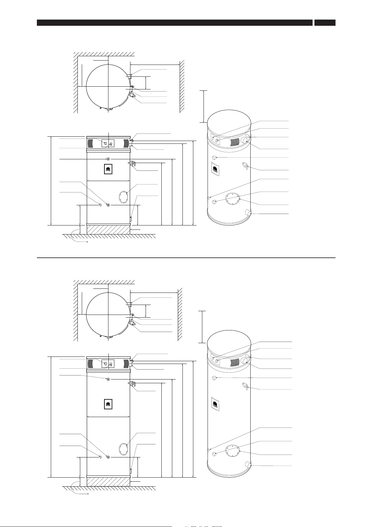
ECOFLO MODELS EC230/600, EC230/700, EC230/960
1
359
1334
1080
1016
330
Flue exhaust/
c
ondense outlet
Cleanout
a
ccess
R
ight side of plinth must not protrude
past edge of heater outer casing
330
150
1448
T&P Valve
c
onnection
3
/4" BSP Gas connection
Combustion air inlet
1
1
/2" BSP Hot
water outlet
1
1
/2" BSP Cold
w
ater outlet
D
rain/secondary
return
connection
7
18 dia.
ON/OFF Switch
Thermostat knob
NB: Unit must be installed on
minimum 150 mm high plinth
100 mm
clearance
F
lue exhaust outlet
210
500mm Clearance for
flue system
3
/4" BSP Gas connection
Combustion air inlet
T&P Valve connection
Flue exhaust/
c
ondense outlet
Cleanout access
T&P Valve connection
3
/4" BSP Gas
c
onnection
C
ombustion air inlet
1
1
/2" BSP Hot
water outlet
1
1
/2" BSP Cold
water outlet
Drain/secondary
return connection
ON/OFF Switch
Thermostat knob
450mm service clearance
ECOFLO MODELS EC380/740, EC380/980, EC380/1220, EC380/1400, EC380/1900
1899
1857
1588
1524
330
Flue exhaust/
condense
outlet
Cleanout
access
Right side of plinth must not protrude
past edge of heater outer casing
330
150
1972
T&P Valve
connection
3
/4"BSP Gas connection
Combustion air inlet
1
1
/2"BSP Hot
water outlet
1
1
/2"BSP Cold
water outlet
Drain/secondary
return
connection
718 dia.
ON/OFF Switch
Thermostat
knob
NB: Unit must be installed on
minimum 150 mm high plinth
100 mm
C
learance
F
lue exhaust outlet
210
500mm Clearance for
flue system
3
/4"BSP Gas connection
Combustion air inlet
T&P Valve connection
Flue exhaust/
condense outlet
Cleanout access
T&P Valve connection
3
/4"BSP Gas connection
Combustion air inlet
1
1
/2"BSP Hot water outlet
11/2"BSP Cold water
outlet
Drain/secondary return
connection
O
N/OFF Switch
Thermostat knob
4
50mm service clearance
7
Page 8

SEC TIO N 3 • INSTALLATION
8
INSTALLATION
INTRODUCTION
THE LAW REQUIRES THAT INSTALLATION
IS CARRIED OUT BY A PROPERLY QUALIFIED
PERSON
Installations must be carried out in accordance with Gas
Safety (Installation and Use) Regulations 1998, Building
Regulations, The Water Supply (Water Fittings)
Regulations 1999 and any requirements of the local Gas
Supplier, Local Authority, Water and Fire Authorities and
the current British Standards and Codes of Practice listed
in Section 1.
LOCATION
The location selected for installation of the water heater
must allow the provision of a satisfactory flue, adequate
air supply, drain facilities and must be well illuminated.
A purpose built boiler room or compartment is strongly
recommended.
A manual valve for isolation of the plant room should be
installed in the gas supply; it should be clearly identified
and readily accessible for use at all times.
weight of the heater when filled with water, and should
satisfy the requirements of the Local Authority & Building
Regulations.
Any combustible material adjacent to the heater must be
placed and shielded as to ensure that its temperature
does not exceed 66°C (150°F).
All service clearances for the water heater must be
maintained as specified in this Installation Manual.
If a purpose built plant room is not available, measures
should be taken to protect the water heater from damage
and prevent any extraneous matter from being stored on
or around the water heater. See BS 6644 Clauses 4, 5
and 6 for details.
The water heater must not be installed in any location
which contains a bed, bath or shower. There must be
easy access to the plant room and water heater at all
times.
The water heater must be located in an area where
leakage from the tank, water connections or the
combination temperature and safety valve will not result in
damage to the area adjacent to the water heater. When
such locations cannot be avoided, a suitable drain tray
must be installed under the water heater. The drain tray
must be no deeper than 38mm (1.5in) and have a
minimum length and width of 100mm (4in) wider than the
heater. The drain tray must be piped to an adequate drain
using 20mm (0.75in) diameter pipe, angled for proper
drainage.
Access must be provided around the water heater to
provide adequate clearance for its servicing and
operation.
The floor and plinth on which the heater is installed must
be flat, level and of sufficient strength to withstand the
Page 9

INSTALLATION • SECTION 3
9
FEATURES
ECOflo is the latest addition to the Andrews range
of condensing storage water heaters and is
designed for large domestic, commercial and
industrial applications.
The high efficiency units incorporate Vitraglas
®
silica glass lined tanks to provide protection against
the corrosive effect of hot water and therefore a
longer working life.
The condensing glass-lined ultra high thermal
efficiency storage water heater features a low NO
x
pre-mix power burner that is quiet in operation, a
98% gross efficiency that keeps running costs to a
minimum and flueing arrangements that offer
unsurpassed installation flexibility.
ECOflo – A NEW STANDARD IN
CONDENSING STORAGE WATER
HEATING
The ECOflo range comprises eight models in two storage
capacities – 230/380 litres – with heat outputs ranging
from 35kW to 79kW and recovery rates of up to 1400
litres/hour through a temperature rise of 50°C.
A thermal efficiency rate of up to 98% gross puts ECOflo
at the top of the class and leads to greater economy.
In addition to outstanding performance characteristics, all
ECOflo models can be flued either vertically or horizontally
as room sealed balanced flue appliances, using
concentric flue components supplied by Andrews,
offering the ultimate in siting and installation flexibility.
All models incorporate Correx Powered (maintenance
free) Anodes as standard which substantially reduce
service time and costs. The factory fitted Hydrojet®
sediment reduction system on the cold inlet connection
helps to prevent sediment build-up at the base of the
tank, giving a longer and more efficient working life.
INSTALLATION
This water heater contains the following features:
MAIN POWER ON/OFF SWITCH
The front panel of this water heater has an illuminated
ON/OFF switch, which is lit when the main power is
turned on to indicate power to the water heater.
COMBUSTION SYSTEM
The ECOflo is equipped with a self-compensating,
negative pressure pre-mix combustion system. As the
blower operates, air is drawn in through the air intake and
into a venturi, which pulls gas from the gas valve. The gas
and air is then mixed in the combustion blower and sent
through the transition tube into the burner. The Hot
Surface Ignition System (HSI) then ignites the gas/air fuel
mixture to produce the flue products (combustion). The
flame sensor signals the ignition module, (described
below) that a flame is present.
IGNITION MODULE
The ignition module provides the timing for the
combustion system. A sequence of operation (SOP) is
described in “Section 5 – Operating Instructions.” As the
combustion system progresses through the SOP, LED’s
illuminate, allowing accurate trouble-shooting should the
need arise. If a failure occurs, the system will “blink” the
LED that corresponds to the failure as described in the
“Section 6 – Troubleshooting Guide.”
ADJUSTABLE THERMOSTAT
The ECOflo is equipped with an adjustable thermostat to
control water temperature. Hot water temperatures
required for kitchen sinks, sluices, cleaners’ sinks and
washdown applications can cause scald burns resulting
in serious personal injury and/or death.
The temperature may be adjusted from approximately
27°C to 82°C. It is recommended that lower
temperatures be used to avoid the risk of scalding. (Refer
to the “Warnings” and the section on SCALDING in
“Section 3 – Water Connections.”) It is further
recommended, in all cases, that the water temperature be
set for the lowest temperature, which satisfies hot water
needs. This will also provide the most energy efficient
operation of the water heater and minimises scale
formation.
The top immersion well of the single bulb controller also
contains the high limit (energy cut-off) sensor. The high
limit switch interrupts the main burner gas flow should the
water temperature reach approximately 93°C.
Should the high limit switch activate, it must be manually
reset. This can be accomplished by depressing the red
button on the control panel once the water temperature
of the tank has dropped below 71°C.
Please contract Andrews Water Heaters (details listed on
the Data Plate) if continued high limit switch operations
occur.
CONDENSATE DRAIN
The ECOflo is a condensing type unit and requires a drain
to be located in close proximity to allow the condensate
to drain safely. The condensate drains from the unit at the
base of the exhaust tee piece located near the bottom of
the unit. The exhaust tee is provided with a 32mm dia
connection. A condense siphon is supplied in the flue kit
which should be connected to the 32mm connection at
the base of the exhaust tee. The siphon outlet must be
connected to a 40mm dia OD plastic waste system. If the
Page 10

10
SEC TIO N 3 • INSTALLATION
condense is allowed to build-up then the exhaust outlet
will become blocked and cause improper operation of the
water heater. The water heater will need to be raised off
the floor, on a concrete slab or base, to utilise a low
profile condensate pump to allow free drainage of
condensate from the outlet fitting. The condensate plastic
drain pipe installation should slope to a suitable drain.
CLEANOUT
All models are equipped with a cleanout opening to aid
the removal of hard water deposits from the tank bottom.
If this water heater operates under hard water conditions,
the following should be performed at least every 3
months: Turn off water supply and drain the water heater.
Remove the cleanout jacket cover and tank cover. When
cleaning the tank, care must be taken to avoid trying to
break deposits loose as this could damage the glass
lining and shorten the life of the water heater. After
cleaning, re-install the cleanout tank cover and jacket
cover, and refill with water. Refer to the section, “Section
6 – Maintenance” in this Installation and Operating
Instruction manual for the procedures for filling and
draining the water heater.
ELECTRICALLY POWERED ANODES
All models are supplied complete with Andrews’ Correx
Powered Anode system. The anodes are non-sacrificial
and therefore do not require any maintenance or
replacement. For this reason, the service clearance
required above the water heater can be reduced quite
significantly. Correx anodes require a permanent power
supply, this is all pre-wired and the anode system can be
located at the top of the heater, beneath the top cover.
SERVICE PANEL
The service panel is located behind the service panel
access cover, which is located by the exhaust outlet tee
piece near the bottom of the water heater. This panel
contains a pressure switch to monitor for excess pressure
in the exhaust pipe from a blocked vent condition.
A collector high limit switch is used to monitor the
ambient temperature between the first pass collector and
the exhaust collector. This is a manually re-settable
switch. If this switch continues to trip, please contact
Andrews Water Heaters.
TECHNICAL DETAIL
Thermal Efficiency up to 98.0% – Fully condensing
design.
Three Pass Flue System – The three pass flue system
keeps the hot combustion gases moving at a high
velocity. The combination of high turbulence and velocity
causes an enormous rate of heat transfer into the water.
Low NOx Premix Power Burner – Developed for the
ECOflo Range, a turbulent flame shoots down the
submerged combustion chamber. This turbulence causes
a thorough mixing of the gas and air for optimum
combustion and high heat transfer efficiencies.
Submerged Combustion Chamber – Submerging the
combustion chamber in the centre of the water storage
tank minimizes radiant heat loss and improves efficiency.
Non-CFC foam insulation – Surrounds the tank
surface, saving energy by reducing heat loss.
Electronic Controls – Adjustable electronic thermostat
27°-82°C recycling Energy Cut Off (E.C.O) shuts off all
gas in event of an overheat condition.
Zero Inch Clearance – The ECOflo external jacket is
cool to the touch and is approved for zero inches to
combustibles for unsurpassed installation flexibility.
Vitraglas
®
lined tank – Andrews Water Heater tanks are
protected from the corrosive effects of hot water by an
exclusive ceramic porcelain-like coating. Our high silica
Vitraglas® lining provides a tough interior surface.
Electrically powered anodes – Each ECOflo product is
supplied with a factory fitted Andrews Correx Powered
Anode system. This significantly reduces service time due
to the anodes being maintenance free.
Factory installed Hydrojet
®
Sediment Reduction
System – Cold inlet sediment reduction device made of
stainless steel for increased durability. Helps prevent
sediment build up in tank.
ACCESS LID
Access for servicing the water heater from the top is easy.
Remove the two latches and the metal screw at the front
centre of the top to remove the lid for accessing the
heater controls. The lid must be replaced and re-latched
upon completion of servicing.
Factory installed dielectric fittings – All heaters are
equipped with special water heater nipples for longer
heater life. No special dielectric fittings to buy.
Flexible Venting – The ECOflo range can be flued
vertically or horizontally with the Andrews 100/150mm
concentric flue pipe system.
The maximum flue run length is sixteen metres from the
appliance connector to the terminal.
Page 11

The overall length is reduced if an elbow or condensate
trap is fitted (see below).
Determining required flue length –
1. Determine the total length of straight concentric flue
pipe (in metres) required for the installation.
2. Add 1.2 metres of flue for every 90°C elbow.
3. Add 0.7 metres of flue for every 45°C elbow.
4. Add 1.5 metres for condensate trap.
5. Total flue length cannot exceed “Maximum Length” in
the above paragraph.
NOTICE: Do not include the flue terminals in
determining maximum flue installation length.
Three year limited warranty on storage tank
– Heavy gauge steel automatically formed, rolled and
welded to assure a continuous seam for glass lining.
INSTALLATION • SECTION 3
11
One year limited warranty on parts
Page 12

12
SEC TIO N 3 • INSTALLATION
IGNITION SYSTEM COMPONENTS
Fenwal 35-655305-121 Hot Surface Ignition Control, CE
listed. 3 Trials for Ignition, 15 second pre-purge timing, 15
second igniter heat up time, 4 second trial for ignition, 24
volt input to control.
Omron G2R-1A-T-AC24 relays (VDE listed) used for high
voltage switching of hot surface igniter and combustion
blower from the 24 volt outputs of the Fenwal control.
Saint Gobain 230 volt hot surface mini igniter.
Honeywell VK8115 gas valve (negative pressure regulator)
with matched venturi sizes for mixing gas with
combustion air.
EBM RG130 (36-6 and 43-9 kW/hr input sizes) and
RG148 (58-3 through 85-0 kW/hr. inputs) pre-mix
combustion blowers. 230 volts, 50/60 Hz.
Burner: Acotech (Bekaert Combustion Technology) Premix burner with stainless steel mesh outside knit.
Blocked Vent Pressure Switch: Honeywell IS20378-5770
normally closed pressure switch. Contacts open in the
event of a severe blockage of the flue outlet.
2nd Pass Flue Collector: At the top of the tank, the flue
gases from the 4” flue tubes collect in a heavy gauge
steel collector to redirect the flue gases down eight 2”
diameter flue tubes.
2” diameter flue tubes are glass lined on the inside as well
as outside to prevent corrosion from flue gas condensate.
Stainless steel flue baffles inside the 2” flue tubes
turbulate the flue gases to aid heat transfer. Flue
temperatures are reduced from 260-340°C from the
second pass collector to 54°C or less in the flue exhaust.
3rd Pass Collector: The flue gases from the bottom of the
2” flue tubes are collected at the bottom of the tank in a
stainless steel flue collector, where the exhaust gases and
condensate exit out through a short Stainless Steel pipe
extending outside the jacket that connects to the coaxial
concentric flue system.
VENTING SYSTEM
A condensate tee with a silicone seal is connected to the
plastic exhaust pipe and interfaces with the flue system.
The tee connection has a 32mm condensate drainpipe
connection to allow the siphon to be fitted. The waste
pipe will then be taken from the siphon outlet to drain.
THERMOSTAT AND HIGH LIMIT
CONTROLS
Honeywell L6189A 2043B aquastat. Temperature
adjustment range: Below 40°C to maximum of 82°C (dial
stop to limit maximum temperature). Differential set to
4°C Capillary bulb inserts into well in top of tank.
Thermostat dial adjustable on top front section of water
heater jacket.
Honeywell L6189C 2023 1 High limit control. Set point
fixed to 93°C with screw. Mounted to control panel inside
control compartment. Capillary bulb inserts into separate
well in top of tank. Manual reset control button accessible
through clearance hole in control panel.
HEAT EXCHANGER
Burner fires down into 8” diameter flue tube transferring
the radiant heat from the burner flame into the tank water.
1st Pass Flue Collector: At the bottom of the tank, a
refractory lined heavy gauge flue collector re-directs the
flue gases from the 8” flue tube to pass through two 4”
diameter flue tubes to the top of the tank.
4” diameter flue tubes have stainless steel baffles to
turbulate the flue gases to improve heat transfer.
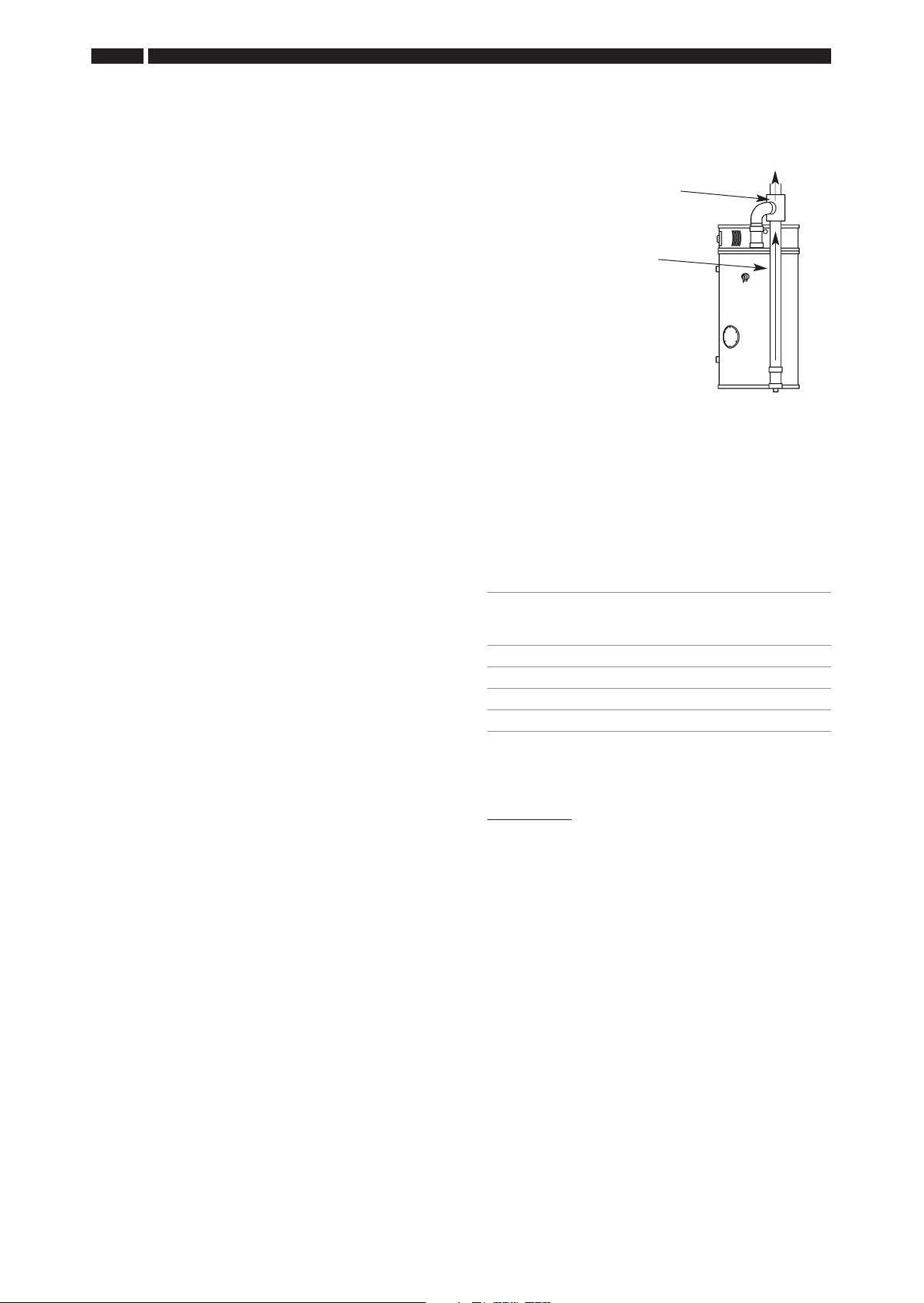
A section of aluminium flue pipe will run to the top of the
water heater to connect to the air intake tee.
The intake tee adapts to the concentric flue pipe and has
an elbow to connect to the combustion air intake pipe.
The 100/150 mm dia. Andrews’ concentric flue pipe will
then run to the horizontal or vertical flue terminal.
Maximum concentric flue for this product is 16 metres.
Each additional 90° elbow is equivalent to a reduction of
1.2 metres of straight flue pipe.
Each additional 45° elbow is equivalent to a reduction of
0.7 metres of straight flue pipe. If a condensate trap is
installed, this is equivalent to a reduction of 1.5 metres of
straight flue pipe.
WATER CONNECTIONS
Front hot and cold 1½” BSP (male) water supply
connections.
GAS CONNECTIONS
¾” Gas Inlet Nipple for BSP connection to gas supply.
1” Gas Inlet Nipple for BSP connection to gas supply for
the EC380/1900 model.
Page 13

INSTALLATION • SECTION 3
13
UNPACKING
INSPECT SHIPMENT CAREFULLY FOR ANY SIGNS
OF DAMAGE
1. All equipment is carefully manufactured, inspected
and packed.
2. Any claims for damage or shortage in shipment must
be filed immediately with Andrews Water Heaters as
detailed on the warranty card.
LOCATION
Locate water heater in front of final position before
removing crate.
1. LOCATE so the flue installation connections will be as
short and direct as possible
2. THIS WATER HEATER IS NOT SUITABLE FOR
INSTALLATION ON A COMBUSTIBLE FLOOR. Do
not install this water heater on carpeting.
3. FOR EVERY INSTALLATION, provide a solid level
elevated base such as concrete or other suitable pad
to raise the water heater at least 150mm to provide a
slope for the condensate waste to run to a suitable
drain.
4. Minimum clearance to combustible material is 0” for
the Top, Sides and Rear of this water heater.
However, it is recommended that at least 450mm
from the Top, 600mm from the Front, 100mm from
the Left Side and Rear, and 500mm from the Right
Side edge of the water heater be provided for
servicing and ease of installation. See Section 2,
page 5 for diagram. Clearance for servicing may be
reduced down to minimum clearance to combustible
material, but service time and effort may be greatly
increased.
REMOVE CRATE
1. Remove all banding and pry off crate sides carefully
so as not to damage the water heater.
2. Carefully roll/lift the water heater from the crate base.
MOVE WATER HEATER TO PERMANENT POSITION
by sliding or walking. Place on plinth/base as detailed
previously.
LOCATION
KEEP APPLIANCE AREA CLEAR AND FREE OF
COMBUSTIBLE MATERIALS, PETROL AND OTHER
FLAMMABLE VAPOURS AND LIQUIDS.
This water heater MUST be installed indoors.
This water heater MUST be located in an area where the
general public does not have access.
CHEMICAL VAPOUR CORROSION
Corrosion of the internal flue ways and concentric flue
system will occur if air for combustion contains certain
chemical vapours. Such corrosion may result in poor
combustion and create a risk of asphyxiation, as well as
reducing the life of the water heater. Spray can
propellants, cleaning solvents, refrigerator and air
conditioning refrigerants, swimming pool chemicals,
calcium and sodium chloride, waxes and process
chemicals are corrosive. Products of this sort should not
be stored near the water heater or outside by the air
intake (if applicable).
SCALDING
This water heater can deliver scalding temperature water
at any outlet in the system. Be careful whenever using hot
water to avoid scalding injury. To protect against injury,
you should install approved mixing valves in the water
system. This valve will reduce point of discharge
temperature by mixing cold and hot water in branch
supply lines. Such valves are available from your local
plumbing supplier.
CAUTION
Do not drop water heater. Do not bump water
heater jacket against floor.
Do not bump exhaust flue pipe against crate or
other objects. This will damage the heater and
cause it to be inoperable or create nuisance
problems.
Page 14
14
Regulator set to
give 37 mbar
(14.86" wg)
propane
G
as emergencey
c
ontrol at entry
1" Heavy steel
sleeved pipe
t
hrough wall
Steel liner sealed to
pipe at inside end
Gas cock
R
egulator
n
ormally fitted at
t
ank
BULK SUPPLY TANK
Pigtail
assembly
Automatic
change-over
device
Nipple
Propane cylinders must be
outside the building
Cylinder regulator
set to give 37
mbar (14.86" Wg)
propane
Gas emergencey
control at entry
1" heavy steel
sleeved pipe
through wall
Steel liner sealed to
pipe at inside end
Gas cock
SEC TIO N 3 • INSTALLATION
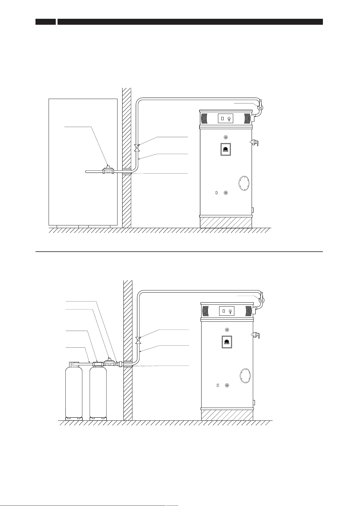
TYPICAL PROPANE BULK STORAGE TANK INSTALLATION
Fig. 1
TYPICAL PROPANE CYLINDER INSTALLATION
Fig. 2
Important: These drawings show a schematic representation only and should not be used for installation
purposes. Contact your gas supplier for authorised installation drawings.
Page 15

INSTALLATION • SECTION 3
15
APPROXIMATE TIME/TEMPERATURE
SCALD CHART
The following chart details the relationship of water
temperature and time with regard to scald injury. This may
be used as a guide in determining the safest water
temperature for the installation.
APPROXIMATE TIME/TEMPERATURE
RELATIONSHIPS IN SCALDS
8.8°C More than 5 minutes
4
51.6°C 1½ to 2 minutes
54.4°C About 30 seconds
57.2°C About 10 seconds
60.0°C Less than 5 seconds
62.8°C Less than 3 seconds
65.6°C About 1½ seconds
68.4°C About 1 second
CAUTION
The water heater and individual shutoff valve
must be disconnected from the gas supply
piping system during any pressure testing of the
system at test pressures in excess of
35mbar/14.0 in wg. The water heater must be
isolated from the gas supply piping system by
closing its manual shut off valve during any
pressure testing of the gas supply system at test
pressures equal or less than 35mbar/14.0 in wg.
The supply line must be capped when not
connected to the water heater.
GAS SUPPLY – NATURAL GAS
The installation of the gas supply must conform,
depending on its size, to the requirements of British
Standards and Codes of Practice listed in Section 1 of
this manual.
A gas meter will be connected to the service pipe by
British Gas plc or its authorised contractor.
The meter and service pipe should be checked by British
Gas, or its authorised contractor, to ensure that they are
adequate to deal with the gas supply to the water
heater(s) in addition to any existing or additional
requirements.
Fit the service gas cock (supplied) to the gas connection
on top of the water heater using a suitable jointing
compound and connect to the gas supply.
The water heater is not intended for operation at higher
than 35mbar (14.0 in wg) supply gas pressure. Higher gas
supply pressures require supplemental reducing service
regulator. Exposure to higher gas supply pressure may
cause damage to the gas controls, which could result in
fire or explosion. If overpressure has occurred, such as
improper testing of gas lines or emergency malfunction of
the supply system, the gas valve must be checked for
safe operation.
Where the water heater(s) is (are) installed in a water
heater house or purpose built compartment, a manually
operated valve for the water heater house must be fitted
in accordance with the Gas Safety (Installation and Use)
Regulations 1998. The valve must be easily identified and
readily accessible.
GAS METER SIZE NATURAL GAS ONLY
Be sure that the gas meter has sufficient capacity to
supply the full rate gas input of the water heater as well as
the requirements of all other gas fired equipment supplied
by the meter. If the gas meter is too small, ask the gas
company to install a larger meter having adequate
capacity.
GAS PRESSURE REGULATION
Main line gas pressure to the water heater should be
maximum 35mbar/14.0 in wg. The inlet gas pressure
must not exceed the maximum value. In some
installations, a regulator sized for the input rating of the
water heater will need to be installed just ahead of the
inlet gas connection to the water heater to reduce excess
gas pressure or surges in gas pressure.
After installation, the system should be pressure tested for
soundness and purged in accordance with BS 6891 or
IM/2 and IM/5 as appropriate.
GAS SUPPLY – PROPANE
Contact Calor Gas who will provide the appropriate type
and size of LPG supply vessel and ensure its safe location
and installation.
The installation of the gas supply must conform to LPGA
Code of Practice, 22 LPG Piping Systems: Design and
Installation, plus the requirements of British Standards
and Codes of Practice listed in Section 1 of this manual.
Andrews Water Heaters are unregulated and a second
stage regulator must be installed to give an inlet pressure
to the appliance as follows:
Page 16

16
SEC TIO N 3 • INSTALLATION
PROPANE: 37mbar (14.86 in wg)
LECTRICAL SUPPLY
E
hen using propane cylinders, connect a minimum
W
number of 47kg cylinders, as listed below, together with a
manifold before connecting to the union.
Use a minimum pipe size of ¾in bore.
wo 47kg Cylinders LEC230/600, LEC230/700
T
and LEC380/740
Three 47kg Cylinders LEC230/960 and
EC380/980
L
Four 47kg Cylinders LEC 380/1220 and
LEC380/1400
EC 380/1900
L
WARNING! PROPANE CYLINDERS MUST BE USED
AND STORED IN ACCORDANCE WITH ‘THE HIGHLY
FLAMMABLE LIQUIDS AND LIQUIFIED
PETROLEUM GASES REGULATIONS 1972’, AND
SHOULD COMPLY WITH LPGA CODE OF PRACTICE
7, ‘STORAGE OF FULL AND EMPTY LPG
CYLINDERS AND CARTRIDGES’.
External wiring to the water heater(s) must be installed in
ccordance with current I.E.E. Regulations for the wiring
a
of buildings and to any Local Regulations that may apply.
he ECOflo range is designed to operate from a 230V,
T
single phase supply. The fuse rating is 5 amps.
he method of connection to the mains electrical supply
T
should facilitate complete electrical isolation of the
appliance, preferably by use of a fused double pole
witch or fused spur box serving only the heater. The
s
disconnection of the supply shall have a contact
separation of 3mm on all poles. The double pole switch
or the water heater electrical supply must be located
f
where it can be easily reached under all circumstances.
The point of connection to the mains electrical supply
should be readily accessible through a cable entry gland
at the rear of the appliance on the combustion assembly
surround.
Connect the electrical supply to the main control panel
terminal block via the cable gland. Mains input cable
should be 0.75mm² 3 core and should be connected to
the mains supply as detailed above.
Mains Voltage: 230V – IP 20
Frequency: 50Hz
Fuse: 5 Amps
Page 17
INSTALLATION • SECTION 3
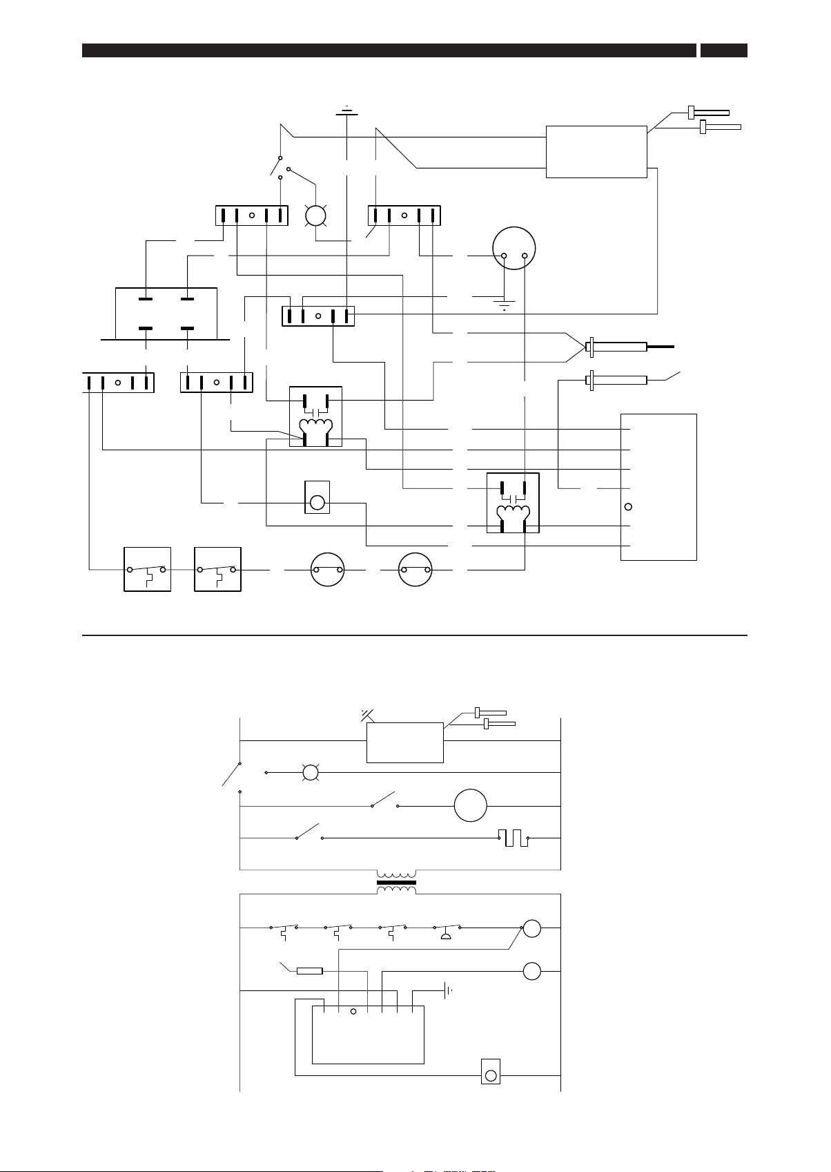
Schematic
N.O.
BL
Igniter relay
Y
WBK
Flame sensor
Combustion blower relay
Blocked
exhaust
P.S. N.C.
Collector
limit N.C.T Stat ECO
Igniter relay coil
Combustion blower
230V
24V
Anodes
ON/OFF
Switch
GND
L1
S1
S2
LED
W
MW1
HSI Control
Fenwal 35-309-121
G
M
Gas valve
R
R
Toggle switch light
N.O.
Igniter
Blower relay coil
Wiring diagram
GN/Y
B
K
Y
B
L
B
K
W
W
W
G
N/Y
W
W
B
K
G
N/Y
B
L
Y
B
K
Y/BK
BL
B
L
Y
BK
BLBL
Y
GN/Y W
B
K
1
3
2
2
30V
T
.B.
G
N
N
T
.B.
C
orrex powered
anode control
Igniter 230V
Flame sensor
B
lower relay
Blocked exhaust
P
.S.
Collector limit
T Stat High limit
G
as valve
I
gniter relay
G
round
T
.B.
T
ransformer
C
ombustion blower
M
230V
24V
2
4V 24V
L
N
1
2
Powered anodes
O
N/OFF
S
witch
4
3
1
5
43
1
5
GND
L
1
S
1
S2
L
ED
W
M
W1
HSI Control
Fenwal 35-309-121
17
Page 18
18
SEC TIO N 3 • INSTALLATION
FLUE SYSTEMS
onventional Flue Option
C
Andrews Water Heaters’ ECOflo is a Balanced Flue, Gas
Water Heater where all air for combustion is obtained
from the outside atmosphere and all flue gases are
discharged to the outside atmosphere. The flue system is
a single concentric (pipe within pipe) design where the
flue products are discharged through the inside flue tube
and the combustion air supply surrounds the flue
surrounded by the outside pipe. The flue system
incorporates both combustion air supply and the flue
exhaust. The flue system component which is outside the
building, takes in the combustion air supply and
discharges the flue products (whilst keeping them
separate) is referred to as the ‘direct flue terminal’.
WARNING!
The direct flue systems MUST be properly installed.
Failure to do so could results in property damage or
personal injury. DO NOT install any damaged
components. Contact Andrews Water Heaters for
replacement parts. The flow of combustion air must not
be restricted. Keep direct flue terminal openings clear of
any objects likely to cause flow restriction.
Direct Flue Terminal
Shall terminate at least 1.5m (5ft) above any forced air
inlet located on the same wall. This provision does not
apply to the combustion air intake of a direct flue
appliance or the circulating air inlet and flue gas discharge
of listed outdoor appliances.
Shall be installed with at least a 300mm (12in) flue
termination clearance from any air opening into a building.
The bottom of the direct flue terminal shall be located at
least 300mm (12in) above ground.
Consideration should be given to the location of the flue
terminal. The flue terminal should be located where the
discharge of flue products does not cause a nuisance.
Consideration should also be given with regard to noise
that may be emitted by this flue system. In all cases the
flue termination must meet the requirements of BS6644.
fresh air ducting
(150mm) direct
Combustion
via “T” piece
from outside,
terminating with
a suitable
xhaust
E
00mm
1
terminal.
The maximum
‘combined’ flue
run is 32 metres.
NB: 100 mm flue section
NOT available from
BAXI Commercial.
Vertical option, maximum
verall run is 32 meters
o
The use of 90°
and 45° bends
will reduce the allowed overall length by 1.2m per 90°
and 0.7m per 45° bend used along the flue run.
NOTE: The overall length does not include the 1m
terminal. The 1m terminal is not to be included in
determining the overall length of the flue.
Maximum Flue Distances (Horizontal or Vertical)
Number of 90° Elbows Maximum length of straight
pipe (excluding flue terminal)
to exterior wall
0 16m (52ft 6in)
1 14.8m (48ft 6in)
2 13.6m (44ft 7in)
3 12.4m (40ft 7in)
NOTE: Each 45° elbow reduces the maximum flue
distance by 700mm (2ft 3in).
IMPORTANT:
Do not exceed the flue distances or
the number of elbows listed above. This may cause
heater malfunction or unsafe conditions.
A suitable terminal guard must be fitted if less than 2
metres above ground level.
OPTIONAL CONVENTIONAL FLUE
(OPEN FLUE)
This is an open flued arrangement where the air is drawn
into the appliance from within the plant room (boiler
house). Permanent ventilation is required to allow correct
operation of the appliance (refer to BS 6644).
Alternatively, the ventilation can be supplied by running
Page 19

HORIZONTAL AND VERTICAL FLUE KITS
INSTALLATION • SECTION 3
19
INSTALLATION PROCEDURE
2. Determine if additional flue components are required
for installation. Refer to the flue component information
Determine location of flue exit.
on pages 21 and 55 for available optional flue
components.
1. The Horizontal or Vertical flue kit that has been
delivered includes the components as listed below and
on page 21. The concentric flue pipe system includes
both the flue exhaust (inside pipe) and combustion air
3. Ensure that the flue terminal location complies with
requirements described within this manual and the
Local Codes of Practice.
(outside pipe). The flue pipe may be cut on the
unflared end (end without gasket) as required for
installation.
4. Measure the vertical and horizontal distance from the
water heater flue connection to determine the number
of components required.
HORIZONTAL FLUE KIT/FITTINGS PACK – 230 LITRE MODELS AWH PART No: B291 SUPPLIED COMPONENTS
Part Description Part Number
Exhaust Outlet Tee c/w Condense Outlet (82500) E860
100mm to Concentric Exhaust Connector (75412) E861
Air intake Tee Piece Connector (82501) E862
Condense Syphon (87436) E863
Horizontal Flue Terminal, 100/150mm (87990) E236
90° Elbow c/w clamp, 100/150 (87890) E205
Gas Cock – ¾”BSP C498
Drain Valve – ¾”BSP C381
Drain Valve Socket – ¾”BSP C103
Installation, Operation and Maintenance Manual E864
VERTICAL FLUE KIT/FITTINGS PACK – 230 LITRE MODELS AWH PART No: B293 SUPPLIED COMPONENTS
Part Description Part Number
Exhaust Outlet Tee c/w Condense Outlet (82500) E860
100mm to Concentric Exhaust Pipe (75412) E861
Air intake Tee Piece Connector (82501) E862
Condense Syphon (87436) E863
Vertical Flue Terminal, 100/150mm (87969) E866
Gas Cock – ¾”BSP C498
Drain Valve – ¾”BSP C381
Drain Valve Socket - ¾”BSP C103
Installation, Operation and Maintenance Manual E864
Page 20

20
SEC TIO N 3 • INSTALLATION
VERTICAL FLUE KIT/FITTINGS PACK – 380 LITRE MODELS AWH PART No: B292 SUPPLIED COMPONENTS
Part Description Part Number
xhaust Outlet Tee c/w Condense Outlet (82500) E860
E
100mm to Concentric Exhaust Pipe (75413) E865
Air intake Tee Piece Connector (82501) E862
Condense Syphon (87436) E863
Horizontal Flue Terminal, 100/150mm (87990) E236
90° Elbow c/w clamp, 100/150 (87890) E205
Gas Cock – ¾”BSP C498
Drain Valve – ¾”BSP C381
Drain Valve Socket – ¾”BSP C103
nstallation, Operation and Maintenance Manual E864
I
VERTICAL FLUE KIT/FITTINGS PACK – 380 LITRE MODELS AWH PART No: B294 SUPPLIED COMPONENTS
Part Description Part Number
Exhaust Outlet Tee c/w Condense Outlet (82500) E860
100mm to Concentric Exhaust Pipe (75413) E865
Air intake Tee Piece Connector (82501) E862
Condense Syphon (87436) E863
Vertical Flue Terminal, 100/150mm (87969) E866
Gas Cock – ¾”BSP C498
Drain Valve – ¾”BSP C381
Drain Valve Socket – ¾”BSP C103
Installation, Operation and Maintenance Manual E864
FLUE SYSTEMS
Optional Components for 100/150mm dia (concentric) Flue
Quantity Flue Length Part Description Part Number
1 1000mm (40in) Flue pipe with clamp E202
1 1000mm (40in) Cutable flue pipe with clamp E203
1 500mm (20in) Flue pipe with clamp E204
1 90° Elbow E205
1 45° Elbow E206
1 Flat roof flashing for vertical flue terminal with adjustable cap E207
1 Roof flashing for pitched roof to suit 150mm (6in) dia flue size E208
1 Wall clamp 150mm (6in) dia. E209
1 Flue condense trap E210
1 Syphon E211
1 Condensate trap pipe kit to syphon E261
Model EC230/600 EC230/700 EC230/960 EC380/740 EC380/980 EC380/1220 EC380/1400
Flue size (concentric) mm 100/150 100/150 100/150 100/150 100/150 100/150 100/150
Max flue run – room sealed (a) m 16 16 16 16 16 16 16
Reduce flue length by 1.2m for 90° bend, 0.7m for 45° bend and 1.5m for a condensate trap.
The ventilation requirements for room sealed flue systems are given on pages 29 and 30.
Page 21

INSTALLATION • SECTION 3
ECOflo 380/1900
HORIZONTAL FITTINGS PACK – Part No: B292
Part No. Description Qty
E910 Concentric measure point 1
860 Exhaust outlet Tee 1
E
E865 100mm concentric exhaust pipe 1
E862 Air intake “T” piece 1
E863 Condense syphon 1
E236 Horizontal terminal 100/150 mm 1
E205 90º elbow/clamp 1
G167 1" BSP M&F gas cock 1
G028
G029
C103AWH
1
⁄2" Drain cock 1
3
⁄4" x1⁄2" reducing bush 1
3
⁄4" drain valve socket 1
21
ECOflo 380/1900
VERTICAL FITTINGS PACK – Part No: B294
E910 Concentric measure point 1
E860 Exhaust outlet Tee 1
E865 100mm concentric exhaust pipe 1
E862 Air intake “T” piece 1
E863 Condense syphon 1
E866 Vertical terminal 100/150mm 1
G167 1" BSP M&F gas cock 1
G028
G029
C103AWH
GENERAL
1
⁄2" Drain cock 1
3
⁄4" x1⁄2" reducing bush 1
3
⁄4" drain valve socket 1
The terminal must be fitted with a guard if less than 2m
above ground level or in a position where it may cause
Flue terminals must be installed in accordance with the
Clean Air Act to ensure the results of combustion are
properly dispersed. The drawing on page 25 shows some
injury to persons resulting from touching a hot surface.
Guards can be ordered with flue components, see table
on page 55.
minimum clearances for the flue terminal. In addition, the
flue terminal should be positioned where it will not cause
a nuisance from noise or from the combustion waste
accumulating. Please contact Andrews Technical Support
Department if advice is needed for a particular installation.
WARNING:
The flue system must be properly installed.
Ensure the inner flue is securely sealed at all the
joints otherwise incomplete combustion may result.
If installed on a roof valley, the terminal should be at least
1m above the highest part of the roof structure and 2.5m
from any adjacent structure.
Do not exceed maximum flue lengths including
elbows.
Page 22
22
E861
(230 Litre)
E865
(380 Litre)
E862
E860
E863
Condense
syphon
Condense pipe
to drain
SEC TIO N 3 • INSTALLATION
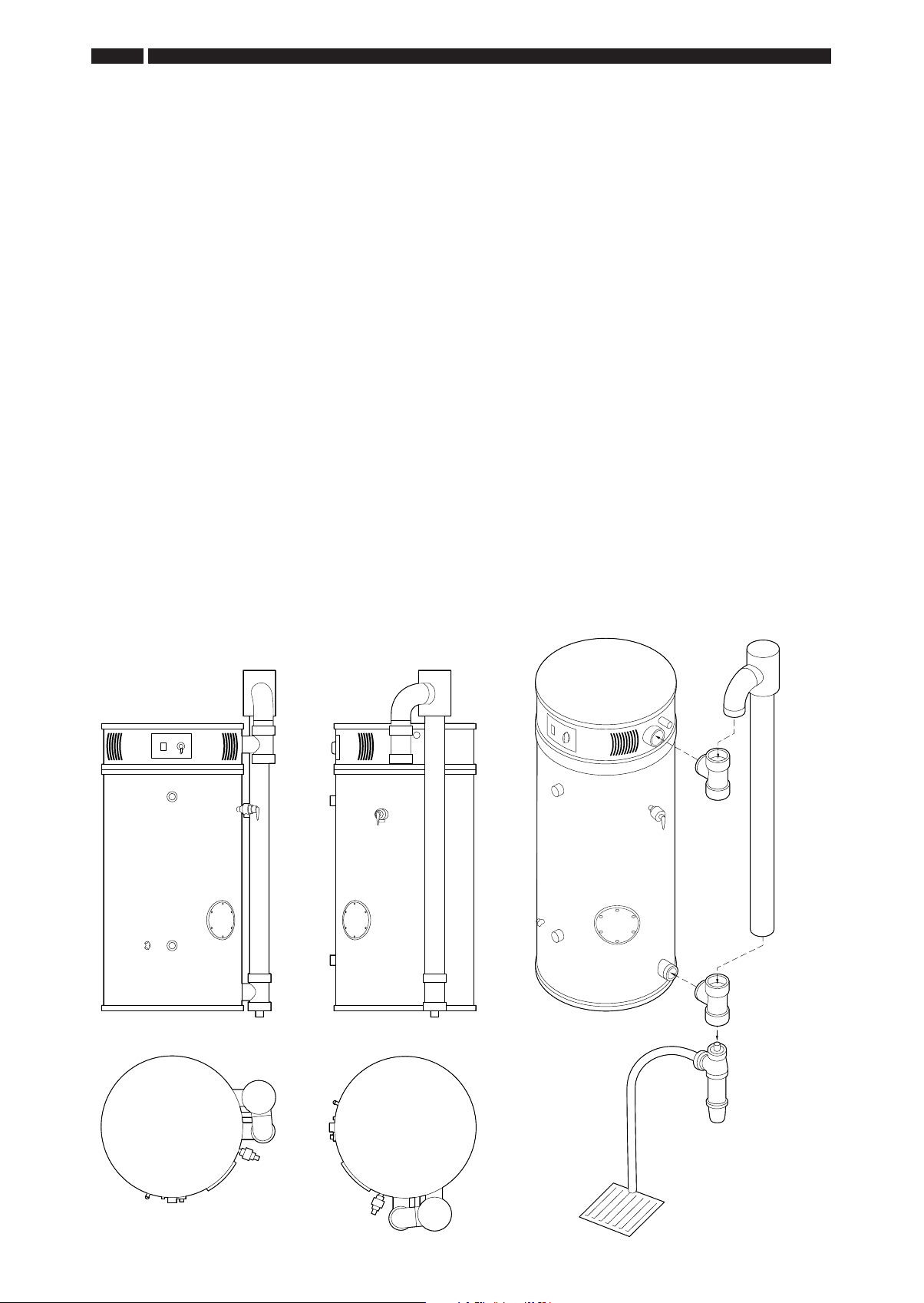
ECOflo 230 & 380 LITRE FLUE SYSTEMS
The ECOflo uses a concentric flue system,150mm
outside diameter with an inner flue of 100mm
diameter.
Flue components fit together with silicon sealing rings and
the flues are retained with sealing clamps. Each heater
can be ordered with either a horizontal or vertical flue kit.
Flue assembly instructions are also included.
Prior to installing the concentric flue system and
terminal, the following must be carried out:
1) Fit item E860 to the stainless steel exhaust outlet
connection on the appliance and ensure that the
condense connection is at the base of the tee piece.
2) Fit item E862 to the PVC air intake connection on
appliance and ensure that the open end is at the top
of the tee piece.
3) Fit item E861 or E865 (depending on the model) to
both previously fitted E860 and E862. Ensure that
both connectors are located correctly. Secure the
100mm dia. vertical section of item E861 or E865 to
heater outer casing with brackets supplied. Ensure
that internal cable is not damaged during installation.
4) Fit item E863 condense syphon to 32mm connection
at base of condense tee (E860).
5) Install 40mm OD plastic waste system from syphon
outlet to suitable drain.
A minimum downward slope of between 3mm to
6mm per 300mm length of water pipe must be
adhered to.
Page 23
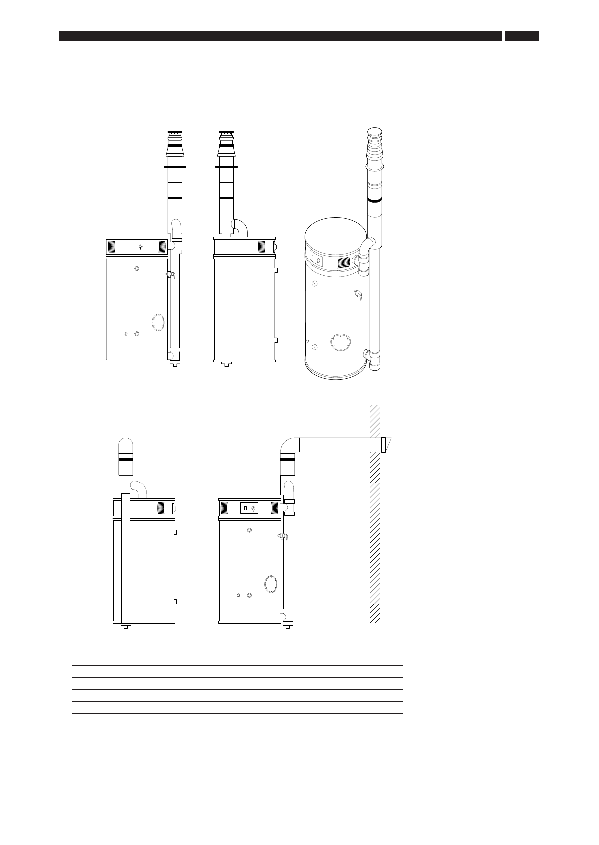
ECOflo 230 & 380 VERTICAL/HORIZONTAL FLUE SYSTEMS
INSTALLATION • SECTION 3
23
Height of concentric section above heater 205mm
Height of concentric sample point 115mm (+/– 5mm)
Height of centre line of 90° bend 178mm (+/– 5mm)
Total height to centre line of bend 500mm (+/– 10mm)
Total height to centre line of bend including EC230 heater: 1948mm (+/– 10mm)
Note: Total height to top of bend 573mm (+/– 10mm)
Total height to top of bend including EC230 heater 2021mm (+/– 10mm)
Total height to centre line of bend including EC380 heater 2472mm (+/– 10mm)
Total height to top of bend including EC380 heater 2525mm (+/– 10mm)
Heights are given from bottom of heater and EXCLUDE a plinth
Page 24
24
SEC TIO N 3 • INSTALLATION
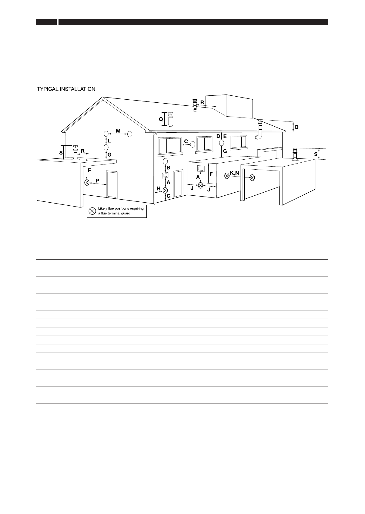
FLUE SYSTEMS
Fig. 3
Terminal Positions with Minimum Distance mm
A Directly below an opening, air brick, opening window etc. 300
B Above an opening, air brick, opening window etc 300
C Horizontal to an opening, air brick, opening window etc. 300
D Below a gutter or sanitary pipework 75
E Below the eaves 200
F Below a balcony or carport roof 200
G Above ground, roof or balcony level 300
H From vertical drain/soil pipework 150
J From an internal or external corner 300
K From a surface or boundary facing the terminal 600
L Vertically from a terminal on the same wall 1500
M Horizontally from a terminal on the same wall (up to 70kW) 300
(above 70kW) 600
N From a terminal facing the terminal 1200
P From an opening in a carport (e.g. door, windows) into the building 1200
Q Above roof 500
R From a vertical structure on a roof 500
S Above flat roof 1000
Page 25
Flue terminal
Inner wall mount
plate
4 Fixing screws
(supplied)
Hole through wall
4 Wall anchors
Flue terminal
Outer wall
mount plate
4 Fixing screws
(supplied)
H
ole through wall
4 Wall anchors
Air intake openings
(must face ground)
FLUE SYSTEMS
INSTALLING THE HORIZONTAL
FLUE TERMINAL
INSTALLATION • SECTION 3
25
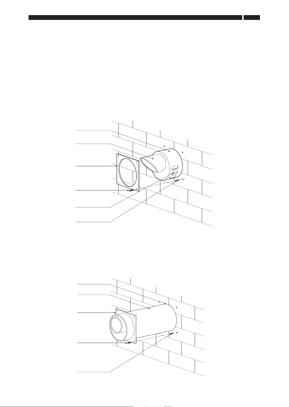
NOTE: The horizontal flue terminal supplied may be used
through outside walls up to 600mm (24in) thick.
1. Horizontal flue Terminal (Through the Wall) supplied
a) Cut an opening of at least 165mm (6.5in) diameter
through to the outside.
b) Slide the flue terminal through the wall opening to the
rib closest to the intake air openings of the terminal
and even with the outside wall.
Fig. 4
c) Slide the outside wall plate over the flue terminal and
fasten to the wall with four screws. Depending on the
wall construction, wall anchors may be required to
reinforce the screws.
Fig. 2
d) Install inside wall plate on the inside wall and secure
with four screws. Depending on wall construction,
wall anchors may be required to reinforce the screws.
Page 26
26
Flue terminal
Storm collar
Flat roof
Roof flashing
(nail & seal to roof)
Flue terminal pipe
Flue terminal pipe
Flue pipe
(from water heater)
SEC TIO N 3 • INSTALLATION
FLUE SYSTEMS
INSTALLING THE VERTICAL FLUE
TERMINAL
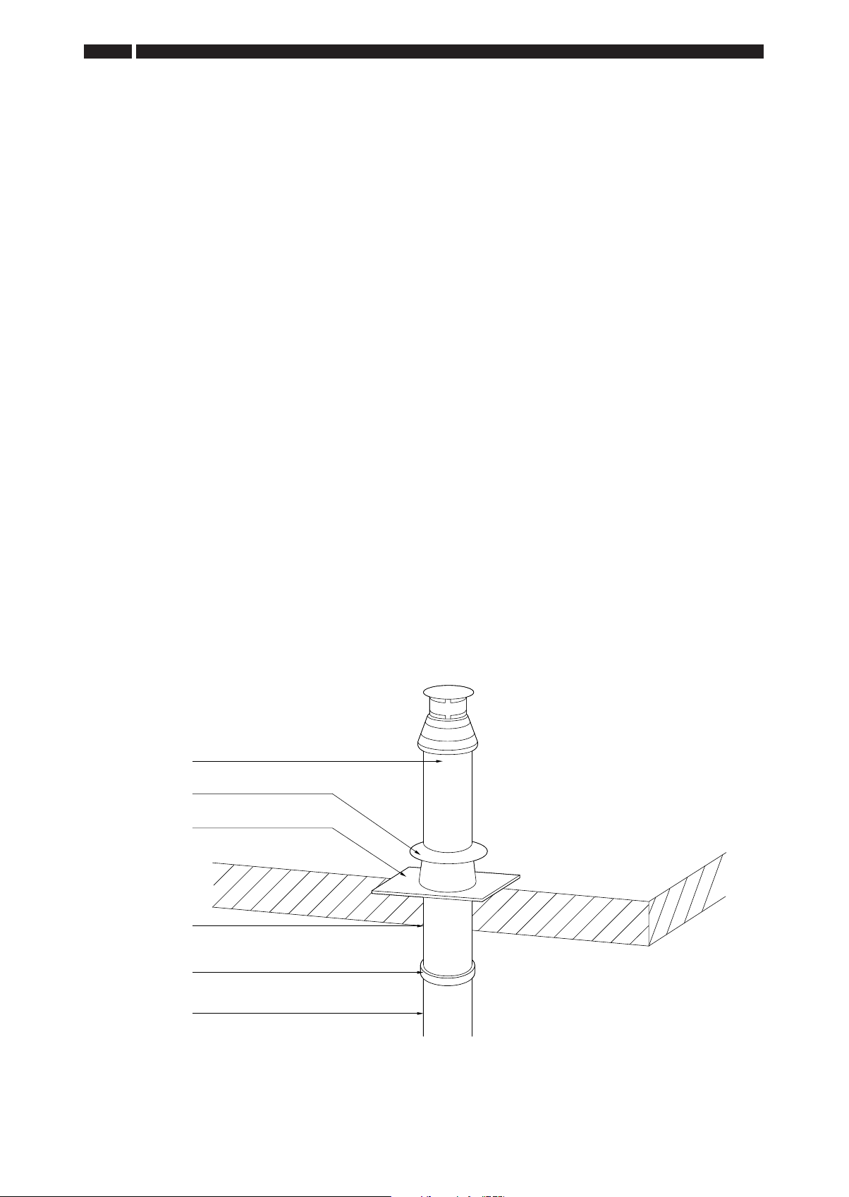
2. Vertical Flue Terminal (Through the Roof)
a) Determine the exact location where the roof flue
terminal will exit the roof, ensuring the flue system
clears all obstructions. For pitched roofs, the flue cap
must be the distance above the roof line as specified
(300mm to base of Flue Clamp, minimum). The top of
the roof terminal may extend up to 760mm (2.5ft)
above the roof line as required.
b) Run the concentric flue system to the proper distance
below the roof sheathing required for the correct
distance of the roof terminal above the roof surface.
See the following sections on installing the rest of the
flue system.
c) Cut a minimum 165mm (6.5in) diameter hole for the
flue centred in the desired location for the roof
terminal, see Fig. 6.
d) Centre the roof flashing over the hole using either the
flat roof flashing or universal flashing for pitched roofs.
e) Slip the storm collar supplied with the roof flashing kit
over the outside of the flue terminal and align with the
flue pipe end below roof opening. Insert the terminal
into the flue pipe.
f) Fasten the roof flashing with nails. Seal the flue
terminal and flashing to the roof.
g) Install the gasketed clamp around the joint between
the flue terminal and flue pipe.
INSTALLING FLUE PIPING SECTIONS
FOR BOTH APPLICATIONS
a) The coaxial flue pipe sections are designed to fit
tightly together and seal with the integral flue pipe seal
and supplied pipe clamps. No silicone caulk or special
tools are required.
b) All flue sections and fittings come complete with
silicone flue pipe gaskets and outside gasketed pipe
clamps for making air tight connections between the
flue pipe connections.
c) Raise the flue pipe to the flue terminal connection with
the gasketed end of the flue pipe towards the flue
terminal. Insert the flue pipe into the flue terminal
connection and grasp the end of the flue pipe while
twisting and pushing the pipe until inserted all the way
into the flue terminal.
d) Connect the outside pipes together using the
gasketed clamps provided. The flue pipes have ribs
located near each end. When the flue piping is
connected, the gasketed clamps shall cover the ribs
and joints of the connecting flue tubes. Support each
pipe section with hangers attached to the supporting
joints in the wall or ceiling.
e) Continue connecting pipe sections together with
clamps and supporting with hangers.
Fig. 6
Page 27
Fit syphon
(part No. E211)
to condensate
trap
40mm OD waste
pipe to drain
Part No. E210 Condense “T”
Gasket end
R
ibs locked beneath
g
asketed clamp
S
traight end
(
ungasketed)
Fig. 7
INSTALLATION • SECTION 3
27
g) The last pipe section may be cut to fit the distance
required to reach the water heater flue connections.
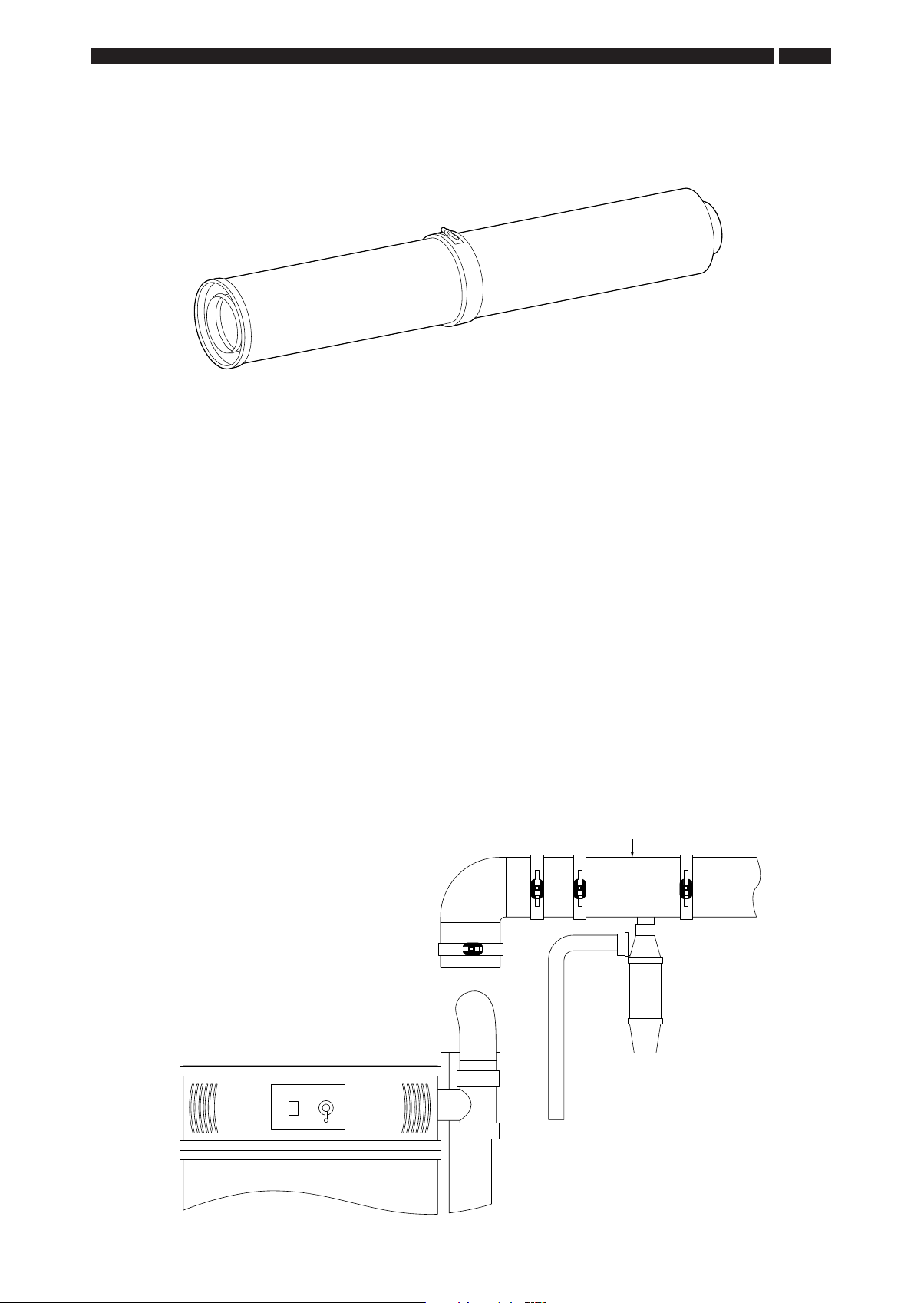
If a flue condensate trap is specified, install the
supplied tap with crimped end into the gasketed end
of the elbow (horizontal flue installations) and clamp
the condensate tee and elbow together. Install the
crimped end of the elbow into the flue connection of
the water heater. On vertical installations, install the
crimped end of the condensate trap directly onto the
water heater flue connection.
IMPORTANT! In order for the condensate trap to
collect and dispose of the condensate from the flue
pipe, the flue system must have a downward slope
of 21mm per metre (0.25in/ft) towards the
condensate trap. The condensate trap must be
installed as close as possible to the flue adaptor to
prevent condensate from accumulating and
draining back into the base of the water heater.
h) Carefully measure the length of straight flue pipe
needed, allowing for about 50mm (2in) insertion into
the elbow. Mark the ungasketed end of the pipe to be
cut and carefully make a straight cut on the outside
pipe to the desired length. Make sure the inside tube is
not cut. Cut the inside flue pipe about 50mm (2in)
more than the outside pipe so that the flue pipe
protrudes slightly beyond the outside pipe. Connect
the flue pipe and clamp at each end.
i) Use the clamp supplied in the flue kit with the stepped
gasket to seal the elbow or condensate trap to the
concentric flue connector.
j) Condensate disposal: Connect syphon (part no. E211)
to the 32mm slip joint condensate trap connector and
install 40mm OD waste pipe suitable drain, (see fig.8).
Note: On all flue installations, for distances over
1.5 metres, we recommend that a condensate trap
is fitted.
Fig. 8
Page 28

28
SEC TIO N 3 • INSTALLATION
AIR SUPPLY AND VENTILATION
CONCENTRIC FLUE SYSTEMS
The following notes are intended to give guidance:
Where the heater is to be installed in a room, NO VENTS
ARE REQUIRED.
Where the heater is to be installed in a COMPARTMENT,
permanent air vents are required in the COMPARTMENT
at high and low level. These air vents must either
communicate with a room or internal space or be direct
to outside air.
The minimum effective areas of the permanent air vents
required in the compartment are as follows:
Air vents should have negligible resistance and must not
be sited in any position where they are likely to be easily
blocked, flooded or in any position adjacent to an
extraction system which is carrying flammable vapour.
Air Vents Areas
Consideration must be given to the position of the high
level ventilation opening. A high level vent must not be
sited within 300mm measured vertically of the flue
terminal.
Grilles and louvres should be so designed that high
velocity air streams do not occur within the space
housing the heater(s).
The grilles should have a total minimum free area for the
water heater(s) in addition to any other requirements as
follows:
• Low level (inlet)
540cm² plus 5cm² per kilowatt in excess of 54kW total
net input.
• High level (outlet)
270cm² plus 2.5cm² per kilowatt in excess of 54kW total
net input.
Position of Air Vents Air from Room for Internal Space Air Direct from Outside
High Level 10cm² per kW Net input 5cm² per kW Net input
Low Level 10cm² per kW Net input 5cm² per kW Net input
In a Room or Internal Space No requirement for Ventilation No requirement for Ventilation
Note: Both air vents must communicate with the same
room or internal space or must both be on the same
wall to outside air.
IMPORTANT:
1. The effective area requirements specified in the table
are related to the maximum heat input of the
heater(s), and are equivalent to those specified in
BS6644.
All mechanical ventilation systems must be fitted with
automatic gas shut off safety systems which cut off the
supply of gas to the heater(s) in the event of failure of
either the inlet or extract fans.
2. The free area of the grilles should not be less than the
size of the recommended ventilation opening.
3. The supply of air to a space housing the heater(s) by
The requirements for air supply by mechanical ventilation
are given in BS6644 Clause 19.3. and in IGE/UP/10 Pt.1.
mechanical means should be;
(a) Mechanical inlet with natural extraction.
(b) Mechanical inlet with mechanical extraction.
The permanent air vents shall be sited away from the
extractor fans. It may be necessary to increase the
ventilation area to compensate for the extractor fan.
NOTE: Natural inlet with mechanical extraction
must not be used.
Where a mechanical inlet and mechanical extraction
system is used, the design extraction rate must not
exceed one third of the design inlet rate.
Page 29
Tank Heater casing
WATER QUALITY AND TREATMENT
INSTALLATION • SECTION 3
29
Where extreme conditions of water hardness exist, scale
can form in any water heating equipment, especially when
the heater is working under conditions of constant heavy
demand and at high temperatures.
In hard water areas, scale formation can occur in hot
water systems and hot water heaters. The higher the
temperature and volume of water used, the more
problematic the scale build-up can be. Water treatment is
normally recommended when the hardness reaches 100
– 150ppm (7 – 10 degrees Clark) and above. This
problem can be minimised by reducing the water
temperature in the heater and by fitting suitable water
pre-treatment equipment.
When installing Andrews Water Heaters in hard
water areas we would recommend that a water
treatment specialist is consulted.
Each Andrews ECOflo Water Heater includes two factory
fitted Correx™ Powered Anodes as standard. These
anodes do not need maintenance or replacement.
The potentiostat which regulates the current to the
Correx™ anode features an indicator light which shows
green to indicate the correct function and red to indicate
a malfunction. The anodes and potentiostat are available
as spare parts if required, (see page 52 for part numbers).
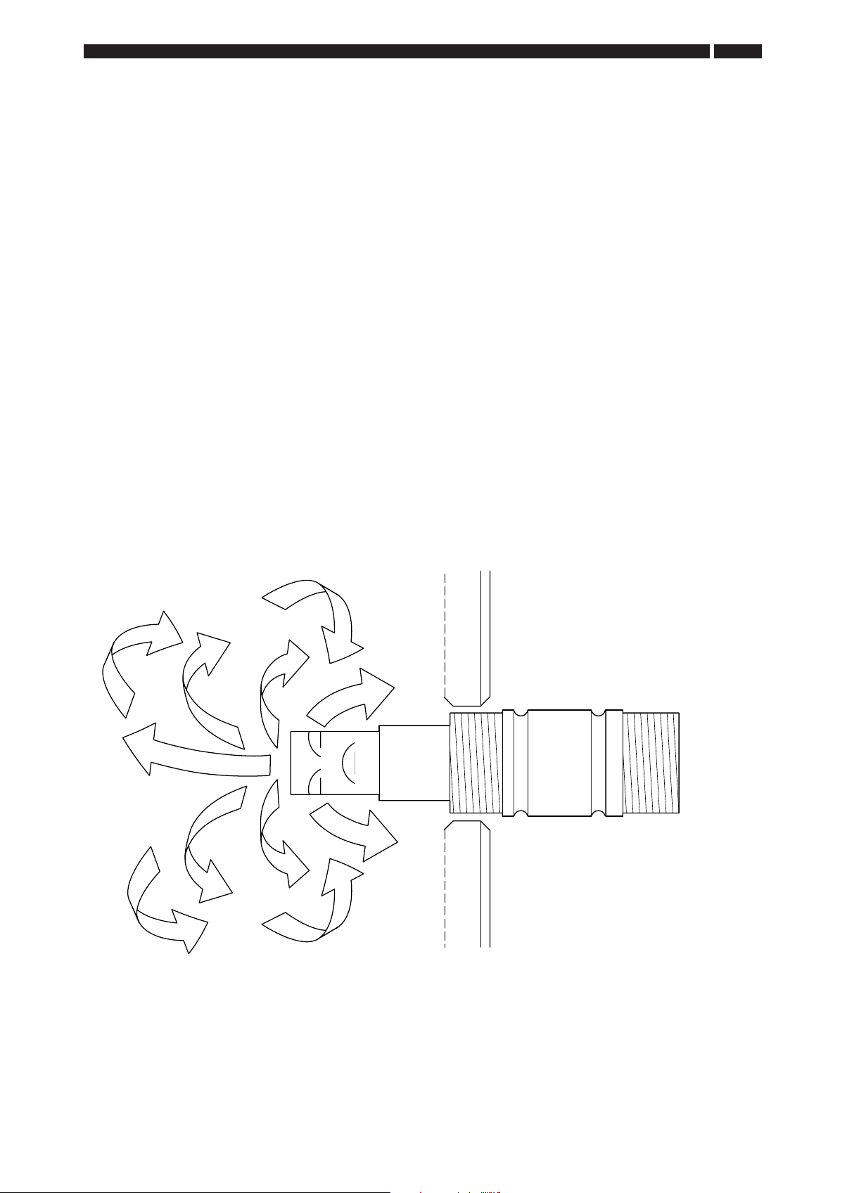
The ECOflo water heater is fitted with the Hydrojet Total
Performance System incorporated in the cold inlet nipple.
The system is designed to increase turbulence and
reduce sediment build-up, reduce thermal stacking and
increase delivery.
Fig. 9
All models now incorporate the new
Hydrojet system on cold inlet side
connections.This system ensures
water is directed onto the tank base
which minimises sediment build-up
from day one of installation.
Page 30
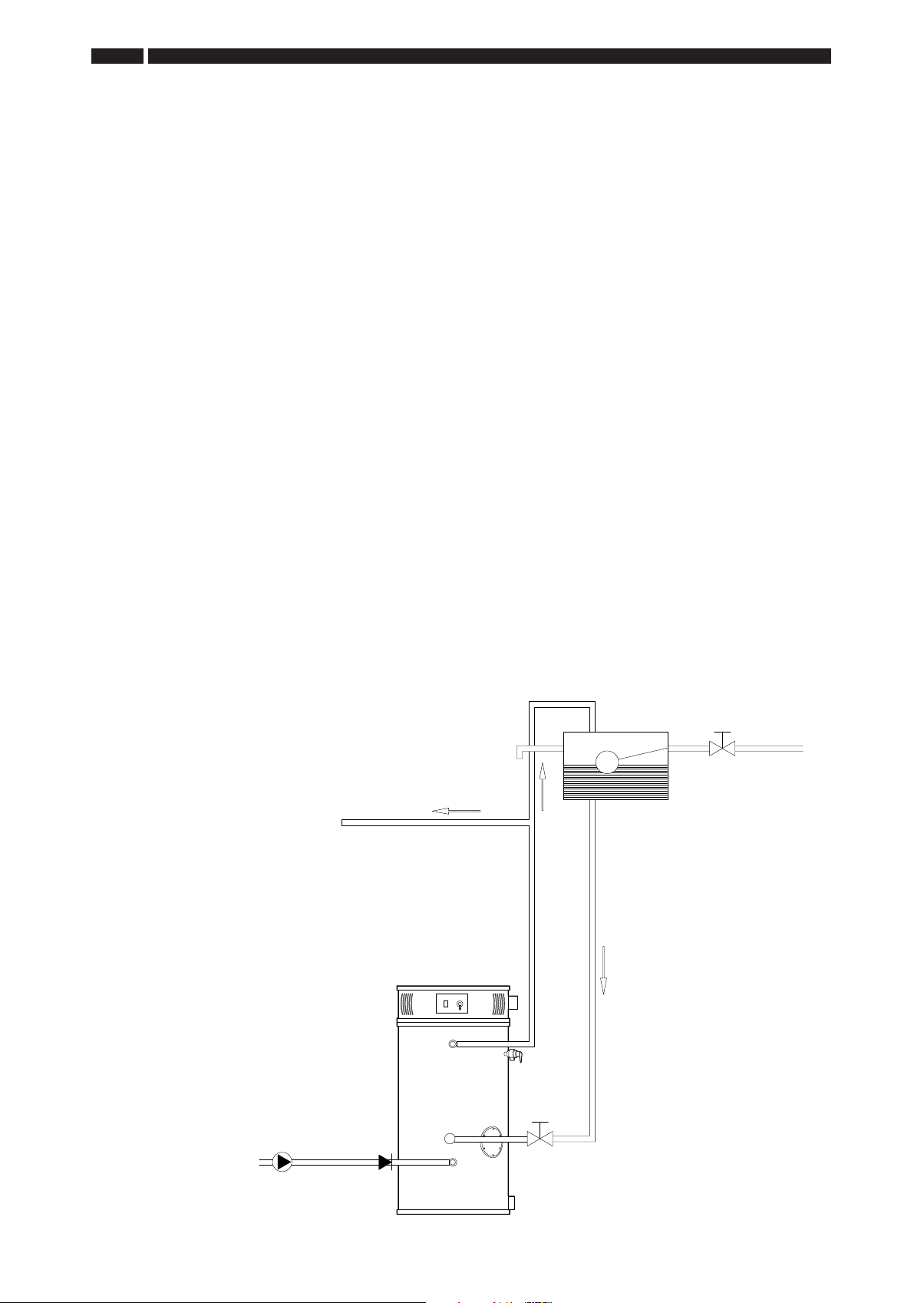
30
Hot water service
Overflow
Open vent Stop valve
Cold water feed
Cold water cistern
Cold water
inlet valve
Secondary return
Bronze pump
Check valve
SEC TIO N 3 • INSTALLATION
WATER CONNECTIONS
VENTED SYSTEMS
The water heater can be fed from a cold water feed
cistern or static water tank.
A safety valve must be fitted as specified in BS 6644
Clause 9.
Minimum 1 bar water pressure is required to allow correct
operation.
The safety valve must be fitted either directly to an upper
tank tapping or not further than one metre along the
outlet flow pipe, size not less than the safety valve.
There must be no valve separating the heater from the
safety valve.
The size of the discharge pipe must not be less than the
nominal size of the safety valve outlet. It should be selfdraining. Any water discharged must be visible and create
no hazard to persons in or about the building.
A low pressure open vented system can be used or,
where the natural circulating pressure is insufficient,
pumped circulation can be employed.
The heater must be fitted with an open vent pipe which
is not valved and which rises continuously to the open
vent. It should be sized with reference to Technical Data,
BS 6644 Clauses 9 and 10 and CP 342. Local
Regulations and Bye-Laws must be observed when
installing the system.
Front Cold inlet / Front Hot outlet water
connections
Assemble onto the 1½” hot water outlet (front) the
required fitting using a suitable jointing compound.
Assemble onto the ¾ BSP thread, the ¾ BSP coupler
socket and drain cock using a suitable jointing
compound.
Water draw-off dead legs should comply with CP 342
Part 2, Table 1 and BS 6700.
NOTE:
When using a secondary return circuit, see Fig. 10
for the location of the return tapping.
It is recommended that all water connections be made
to the heater(s) using union fittings for ease of servicing.
Pipe support intervals should comply with CP 342,
Part 2 Table 4.
After installation of the water system, open the main
water supply valve, flush the system and fill the heater.
Open the hot taps to allow air to escape from the system.
When the system is free of air, close the taps and check
for leaks at the thermostats, drain cock and pipe
connections on the heater.
Fig. 10
Page 31
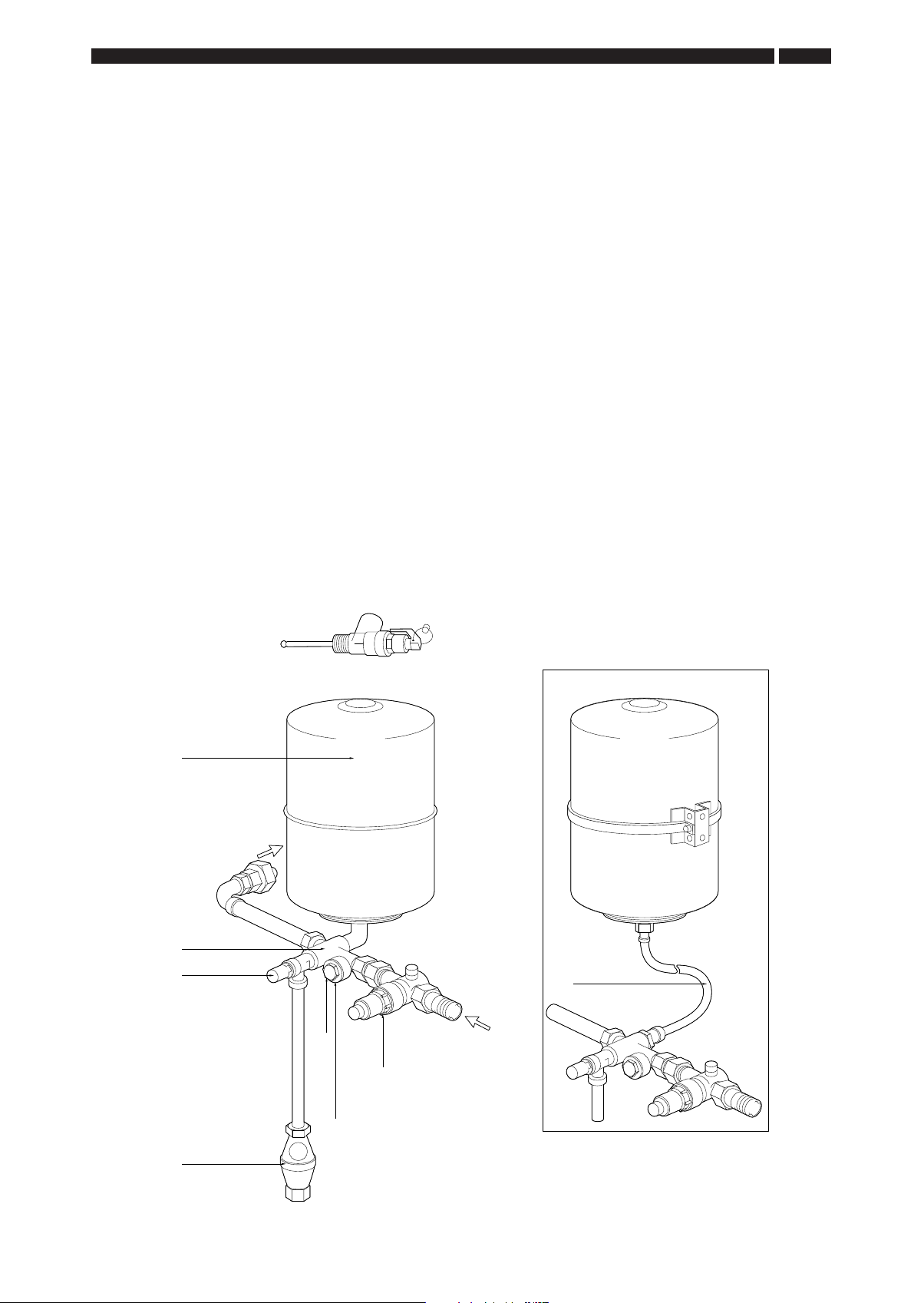
INSTALLATION • SECTION 3
Cold water inlet of
water heater
C3 Expansion valve
C6 Tundish
C1 Combined pressure
reducing valve/strainer
Balanced cold water
take-off (if required)
Cold water
inlet
(a)
C4
NB: Tees, elbows,stop valves and pipework not supplied
C8 Wall bracket assembly
C7 Hose assembly
The wall mounting
assembly C7 & C8
is available as an
optional extra
OPTIONAL PARTS
C
5 Temperature/pressure
relief valve
C2 Check valve assembly
31
WATER CONNECTIONS
UNVENTED SYSTEMS
Unvented Systems should be fitted by an Approved
Installer.
The water heater can be used on unvented hot water
storage systems with the addition of an Unvented
Systems Kit, part number B290, available from Andrews
Water Heaters.
See Parts List on page 44. The wall bracket assembly
(shown below) is available as an optional extra (AWH
Part No – B173).
When used in an unvented system, the ECOflo will
supply hot water at a pressure of 3.5bar (51lbf/in²),
provided that this pressure is available at the mains feed.
During conditions of no-flow, system pressure may rise
to a maximum of 6 bar (87lbf/in²) whilst the burner is
operating. When testing the system, it is recommended
that a maximum test pressure of 8.6 bar (125lbf/in²) is
employed.
The expansion vessel C4 supplied is suitable for the
stored volume of the water heater.
FOR SYSTEMS WITH LARGER PIPE VOLUMES OR
ADDITIONAL STORAGE, EXPANSION VESSELS WITH
MORE CAPACITY ARE AVAILABLE – CONTACT THE
ANDREWS SALES OFFICE FOR FURTHER DETAILS.
The combined temperature and pressure relief valve C5,
must be installed into the horizontal 1” dia. male tapping.
A 1” dia. socket (not supplied) is required as the T&P
valve is also a male fitting. The discharge pipe from items
C3 and C5 must be connected into tundish C6.
When assembling items C1 and C2, ensure that the flow
arrows marked on the components are pointing in the
direction of flow, i.e. towards the water heater.
The cold water for services may be drawn from the 22mm
compression port on item C2(a). The water pressure at
this point will be similar to that available at the hot water
outlet of the water heater. If port (a) is not used, it should
be sealed with the blanking plug supplied.
Fig. 11
Page 32
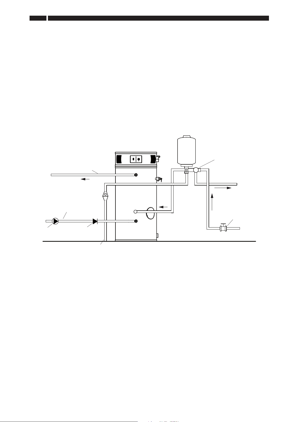
Cold Water
Inlet Valve
Secondary Return Pipe
Hot Water Service
Check ValveBronze
Pump
To D rain
Balanced
Cold Water
Ta ke Off
(Optional)
32
SEC TIO N 3 • INSTALLATION
If higher flow rates are required for the cold water
services, a suitable tee fitting should be fitted to the
pipework upstream of item C1.
The pipework fitted to the tundish outlet should be one
size larger than the outlet pipe of the safety device and
should be terminated at a suitable drain.
(See Building Regulations 1992 Approved Document G3).
All fittings and materials must be suitable for use with
drinking water and listed in the current Water Research
Centre “Materials and Fittings Directory”.
Installation of unvented storage hot water systems must
comply with Part G3 of the Building Regulations 1992.
Typical water service layout for unvented system is
shown in Fig 12.
Fig. 12
Page 33

COMMISSIONING
COMMISSIONING • SECTION 4
33
CAUTION! DO NOT OPERATE THE WATER HEATER
UNTIL THE STORAGE VESSEL IS COMPLETELY
FILLED WITH WATER, WITH WATER RUNNING
FROM ALL HOT TAPS.
Open the main gas supply cock after all connections to
the gas control are completed. Test all connections, using
propriety leak detection fluid.
Filling the Heater with Water
1. Close the water heater drain valve.
2. Open the cold water supply valve.
3. Open several hot water taps to allow air to escape
from system.
4. When a steady stream of water flows from the taps,
the heater is filled.
5. Close the taps and check for leaks at the drain valve,
temperature/pressure relief valve and the hot and cold
water connections.
USER’S SAFETY GUIDE
For your safety, read this section prior to lighting the
appliance.
WARNING
1. Always follow manufacturer’s instructions when lighting
the appliance. Failure to do so may result in damage
to property, personal injury or loss of life.
2. Before lighting, check all around the appliance area for
gas. Be sure to check at low level because some gas
(i.e. LPG) is heavier than air and will settle on the floor.
3. DO NOT make any attempt to re-light the appliance if
the main burner has extinguished. Wait at least 5
minutes to allow for any unburnt gas to disperse.
Ventilate the area if possible.
FOR YOUR SAFETY IF YOU SMELL GAS
1. Turn off gas supply and open windows.
2. Do not operate electrical switches.
3. Extinguish any naked flames.
4. Contact gas supplier if the smell of gas persists.
FOR YOUR SAFETY
Do not store or use petrol, aerosol or other flammable
vapours or liquids in the vicinity of this or any other gas
appliance.
Page 34
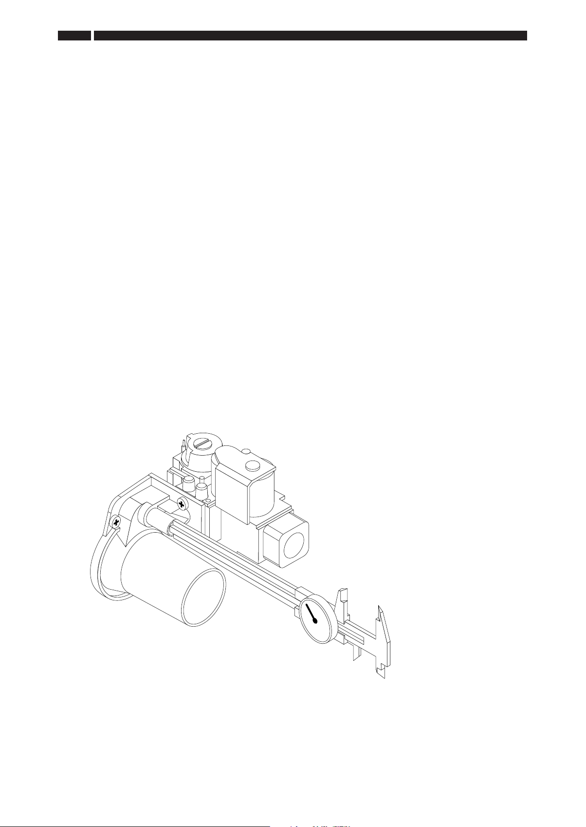
34
SEC TIO N 4 • COMMISSIONING
AIR/GAS MIXTURE ADJUSTMENT
The water heater gas/air mixture is adjusted at the factory
for the proper mixture for optimum combustion and
ignition for the type of gas listed on the rating label. The
water heater should operate properly without requiring
adjustment with the gas type shown on the rating label.
The following is a guide for the correct mixture adjustment
settings in case the gas content is different from the rating
label or ignition is not satisfactory. A combustion analyser
is necessary for making gas/air mixture adjustments to
determine the correct setting.
The water heater cannot be converted from natural to L.P.
gas or L.P. gas to natural gas, without changing the gas
valve/venturi assembly. Using L.P. gas on a water heater
set up for natural gas will result in rough ignitions and
dangerous levels of carbon monoxide.
Do not attempt to adjust the venturi screws without a
properly calibrated CO²/CO combustion analyser. Making
the mixture richer without an analyser to monitor the
adjustments can result in dangerous levels of carbon
monoxide.
G20 (NATURAL GAS, MOSTLY METHANE)
FAMILY
The venturi screw depth, when measured with a set of
callipers (see fig. 13), should be approximately 13.0 –
13.5mm. The CO² range should be set as detailed in
Table 1.
The CO content should be less than 50ppm.
If the CO² content is above the correct percentage, turn
the venturi screw (see fig. 14), clockwise half a turn and
recheck combustion. Repeat, if necessary, until the
correct reading is achieved. Turn the venturi screw anticlockwise if the CO² reading is less than the stated figure
or the ignitions are not smooth.
PROPANE GAS MODELS
The burner assembly is factory adjusted for Propane Gas
on LPG models. The nominal venturi screw setting is the
same as G20 Natural Gas, i.e. 13.0 – 13.5mm screw
depth. A gas inlet orifice is used on LPG models to use
the same venturi screw setting. The CO² range for
propane should be set as shown in Table 1, and
adjustment carried out as detailed above. The CO
content should be less than 50ppm.
Fig. 13
Measurement of
venturi screw depth
with vernier calipers.
Page 35
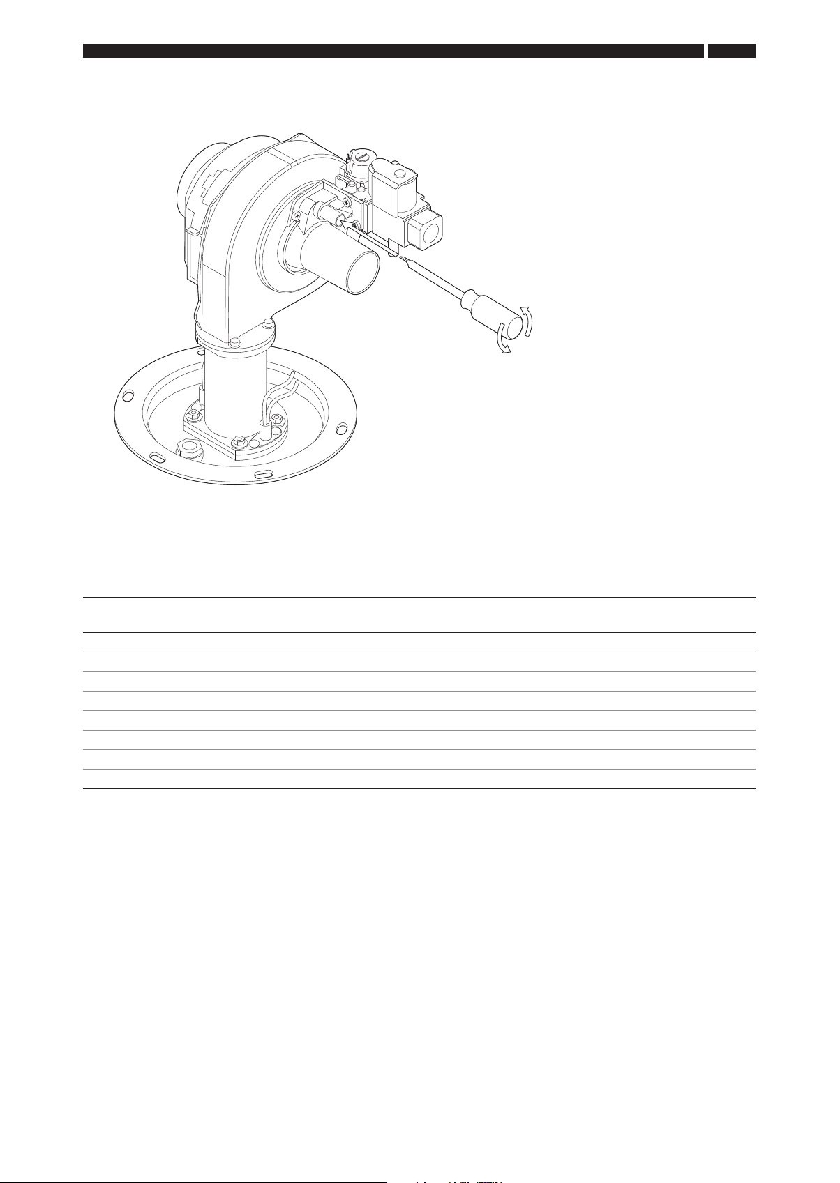
COMMISSIONING • SECTION 4
Adjust gas mixture by
turning venturi screw
(see procedure on
previous page).
35
Fig. 14
CO² PERCENTAGE
Model Reference Input rating Combustion Flue Gas Volume Vent Temperature
kW/hr CO2/CO Cubic metres/hr °C
EC230/600 36.6 11.0%/10 ppm 40 50 – 60
EC230/700 43.9 10.3%/20 ppm 49 50 – 60
EC230/960 58.6 9.7%/10 ppm 63 55 – 60
EC380/740 43.9 10.4%/15 ppm 49 45 – 50
EC380/980 58.6 9.8%/15 ppm 63 50 – 55
EC380/1220 73.2 10.6%/15 ppm 75 50 – 60
EC380/1400 85 11.0%/15 ppm 86 55 – 60
EC380/1900 118.7 11.0%/15 ppm 117 55 – 60
Page 36

36
SEC TIO N 5 • OPERATING INSTRUCTIONS
OPERATING INSTRUCTIONS
WARNING
Water heaters are heat-producing appliances. To avoid damage or injury, there must be no materials stored against
the water heater or flue system and proper care must be taken to avoid unnecessary contact (especially by children)
with the water heater and flue system. UNDER NO CIRCUMSTANCES SHOULD FLAMMABLE MATERIALS, SUCH
AS GASOLINE OR PAINT THINNER BE USED OR STORED IN THE VICINITY OF THIS WATER HEATER OR IN ANY
LOCATION FROM WHICH FUMES COULD REACH THE WATER HEATER.
Installation or service of this water heater requires ability equivalent to that of a licensed tradesman in the field
involved. Plumbing, air supply, flueing, gas supply and electrical work are required.
Light the unit in accordance with the operating instructions label attached to the water heater.
Under no circumstances should the input rate exceed the input rate shown on the water heater rating plate. Over
firing could result in damage or sooting of the water heater.
If the unit is exposed to the following, do not operate water heater until all corrective steps have been made by a
factory authorized, independent service contractor or qualified service professional.
1. Flooding to or above the level of the burner controls
2. External firing
3. Damage
4. Firing without water
5. Sooting
NEVER OPERATE THE WATER HEATER WITHOUT FIRST BEING CERTAIN IT IS FILLED WITH WATER AND A
TEMPERATURE AND PRESSURE RELIEF VALVE IS INSTALLED IN THE RELIEF VALVE OPENING OF THE
WATER HEATER (UNVENTED INSTALLATIONS ONLY).
GENERAL INSTRUCTIONS
TO FILL THE WATER HEATER
1. Close the water heater drain valve by turning the knob
or valve stem clockwise. If alternative water
connections are provided but not used, make certain
they are plugged (i.e. side connections).
2. Open the cold water supply shut-off valve.
3. Open several hot water taps to allow air to escape
from the system.
4. When a steady stream of water flows from the taps,
the water heater is filled. Close the taps and check for
water leaks at the water heater drain valve,
combination temperature and pressure relief valve and
the hot and cold water connections.
SEQUENCE OF OPERATION
1. A call for heat from thermostat
2. Blower ON
3. Pressure switch contacts closed (no exhaust pipe
blockage)
4. Blower pre-purge
5. Igniter warm-up
6. Main burner ON
7. Flame signal confirmed
8. Thermostat satisfied
9. Main burner OFF
10. Blower post-purge
Page 37
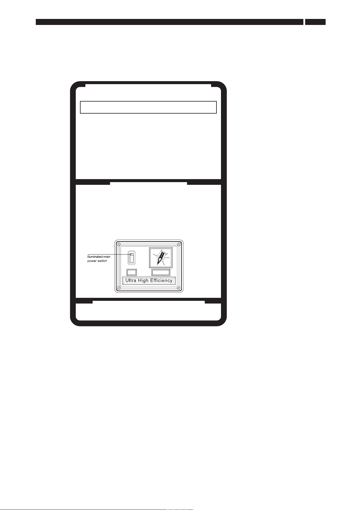
LIGHTING INSTRUCTIONS
FOR YOUR SAFETY READ BEFORE LIGHTING
W
ARNING: If you do not follow these instructions exactly, a fire or explosion
may result causing property damage, personal injury or loss of life
. This appliance does not have a pilot.
A
t is equipped with an ignition device
I
which automatically lights the burner.
o not try to light the burner by hand.
D
. BEFORE OPERATING smell all
B
around the appliance for gas. Be sure
o smell near to the floor because
t
some gas is heavier than air and will
ettle on the floor.
s
WHAT TO DO IF YOU SMELL GAS
Do not try to light any appliance
•
• Do not touch any electric switch
OPERATING INSTRUCTIONS • SECTION 5
Do not use any telephone in the
•
uilding
b
• If you cannot reach your gas
upplier, call the fire brigade.
s
. Turn off mains power to the water
C
heater.
. Do not use this appliance if any part
D
has been under water. Immediately
call a qualified service technician to
inspect the appliance. Replace any
art of the control system and any gas
p
control which has been under water.
37
. STOP! read the safety information
1
bove on this label.
a
. Set the thermostat to lowest setting.
2
3. Turn off all electrical power to the
ppliance.
a
4. This appliance does not have a pilot.
It is equipped with an ignition device
which automatically lights the burner.
Do not try to light the burner by hand.
. Turn off the main power switch.
5
. Wait 5 minutes to clear out any gas. If
6
ou smell gas, STOP! Follow “B” in the
y
afety information above on this label.
s
If you do not smell gas go to the next
step.
7. Set the thermostat to the desired
setting.
8. Turn on main power.
TO TURN OFF GAS TO THE APPLIANCE
LIGHTING INSTRUCTIONS
1. Set the thermostat to lowest setting. 2. Turn off main power switch
Fig. 15
Page 38
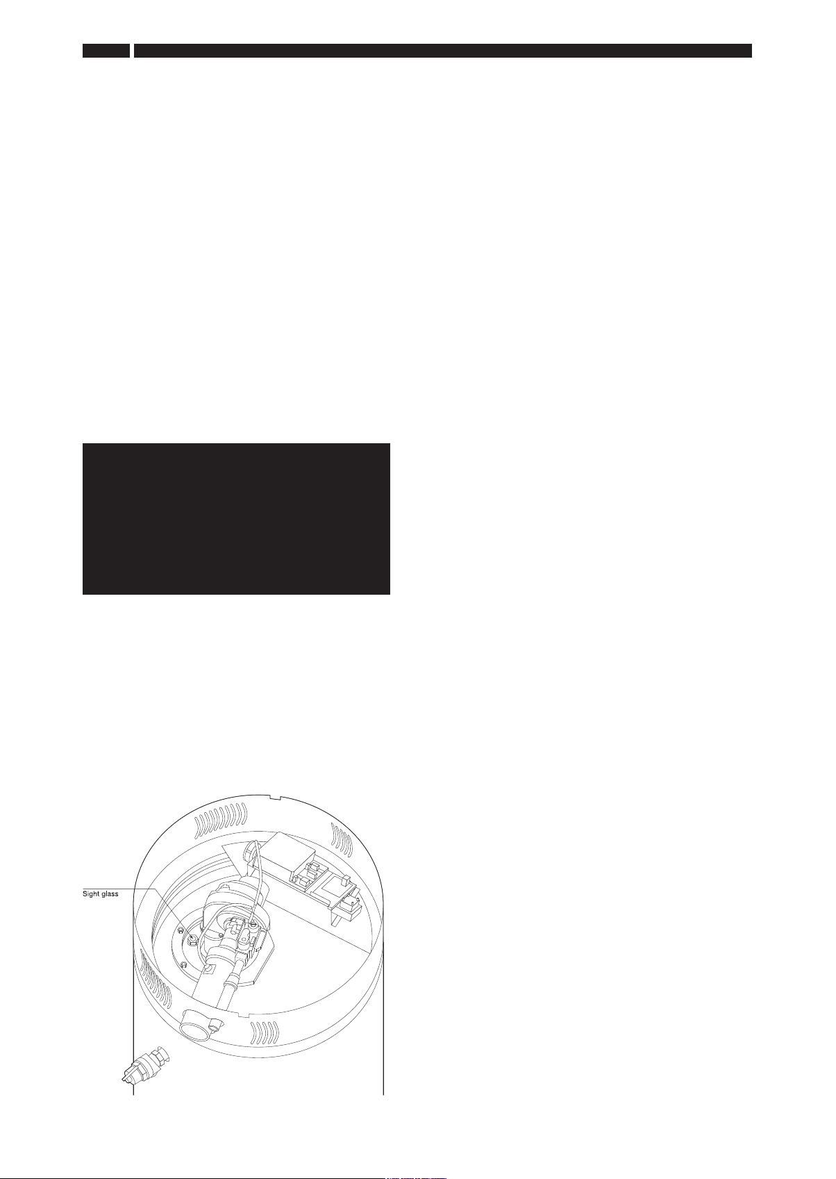
38
SEC TIO N 5 • OPERATING INSTRUCTIONS
TEMPERATURE ADJUSTMENT
During the winter season or any cold period, you may
desire a higher temperature setting to adjust for the cold
incoming water. This adjustment, however, may cause
additional condensation to form on the colder tank
surface. This does not mean the tank is leaking. During
summer months, the warmer incoming water
temperatures will benefit the performance of your water
heater and reduce the amount of condensation
developed.
Condensation does not mean your tank is leaking. Most
of reported tank leaks on installation’s are proven to be
condensation. To avoid unnecessary inconvenience and
expense, make sure the tank is actually leaking before
contacting Andrews Water Heaters.
CAUTION
This water heater is equipped with an energy cut
out device to prevent overheating. Should
overheating occur or if the gas supply fails to shut
off, turn off the manual gas control valve to the
appliance and call a qualified service company.
BURNER FLAME CHECK
If the water heater is to remain idle for 30 days or more, or
is subjected to freezing temperatures while shut off, the
water heater and piping should be fully drained and the
drain valve should be left fully open. Refer to the relevant
section of the Installation and Operating Instructions
Manual for the procedure on draining the water heater.
When properly installed and adjusted, the heater will
require minimal attention. Should it become necessary to
completely drain the heater, follow instructions given in
Section 4, Commissioning.
ECO (ENERGY CUT-OFF)
The heater is equipped with an ECO (Energy Cut-Off)
device, fitted to the control thermostat. It is a temperature
sensitive switch which opens at high temperature,
shutting off gas to the burner in an overheat condition.
When the water has cooled sufficiently, the manual reset
on the ECO needs to be depressed to allow the heater to
be re-lit. If the burner shuts down and is associated with
high water temperature, the ECO is probably operational
and the cause of overheating should be investigated.
TEMPERATURE STRATIFICATION
(STACKING)
When small amounts of hot water are drawn repeatedly,
the thermostat responds to each feed of cold water and
activates the main burners. Each time this occurs, more
heat may be put back in the tank than was drawn off. As
this continues, water in the upper level of the tank gets
hotter than the thermostat setting. The hotter water does
not mix completely with the cold inlet water, but rises in a
‘chimney effect’ to the top of the tank. Many repetitions of
this over a short time results in accumulation of
excessively hot water in the upper part of the tank, even
when the thermostat control is within limits. This is known
as stacking.
To counter this condition, an upper thermostat phial is
fitted which senses abnormally hot water and shuts down
the main burner until the water cools. Most modern
commercial pipe installations include a pumped
secondary return system which keeps hot water moving
continuously throughout the heater. This stabilises
temperatures in the water heater tank and throughout the
pipe system.
Fig. 16
Page 39

MAINTENANCE/SERVICE
MAINTENANCE / SERVICE • SE CTI ON 6
39
INTRODUCTION
Servicing must be carried out by a properly qualified
person.
Whilst giving these instructions for the care of the ECOflo,
it is recommended that checks are carried out by the
installer or local gas service engineer at least annually.
Ensure good ventilation by keeping the heater free of
extraneous materials and clear of dust and lint. Keep
pipework, flue and tops of heaters clear of any
combustible materials. A water softener or scale inhibitor
should be employed in hard water areas. The heater
should be inspected every few months via the hand hole
cleanout and scale or silt deposits removed. Failure to do
so will shorten heater life and may invalidate the warranty.
PRE-SERVICE OPERATIONS
Before servicing, carry out the following operations.
1) Turn off the gas service cock.
2) Turn off the cold water supply to the heater.
3) Turn on the hot water draw-off taps served by the
water heater, or, for multiple installations, turn off the
hot water outlet connection valve and secondary
return valve.
4) Drain down using the drain valve on the heater.
ANNUALLY
Annual checks of the ignition systems, temperature
controls and any other controls are necessary to ensure
continued safe and efficient operation.
The entire combustion system must be sealed for this
water heater to function correctly. Ensure that the burner
access panel is kept tightly sealed. The combustion air
supply tee piece at the side of the heater must be tightly
clamped to the elbow and concentric flue adaptor.
Replace any damaged parts.
The entire exhaust flue system and combustion air supply
must be inspected at least annually for integrity of all
joints and gaskets.
GENERAL
KEEP APPLIANCE AREA CLEAR AND FREE FROM
COMBUSTIBLE MATERIALS, PETROL AND OTHER
FLAMMABLE VAPOURS AND LIQUIDS.
Water heater maintenance includes periodic tank flushing
and cleaning, and removal of lime scale. The unit should
be inspected and adjusted to maintain proper
combustion. Refer to Fig. 17 below, “Suggested
Maintenance Schedule”. A periodic inspection of the flue
installation system should be made.
MAINTENANCE SCHEDULE
Following are the instructions for performing some of the recommended maintenance.
Unit inspection and adjustment should be performed by a competent qualified engineer.
COMPONENT OPERATION INTERVAL REQUIRED
Tank Sediment Removal Every 6 months Flushing
Relief Valve Check Operation Every 6 months Proper Operation
Exhaust & Air Intake System Inspect Every 3 months Joints should be sealed
Ignition System Inspect Annually Clean off dust and dirt
Flue Vent Terminal Clean Inlet Screen As Required Soft Brush
Flue Terminal – Free of Shrubs Monthly Remove object
Horizontal or Vertical & Debris that caused restriction
Combustion System Inspect Monthly Confirm S-OP
Condensate Waste Pipe Inspect Monthly Remove restriction
CORREX POWERED ANODES
As Correx Powered Anodes are fitted as standard to this appliance, no maintenance is necessary.
Page 40

40
SEC TIO N 6 • MAINTENANCE / SERVICE
FLUSHING WATER HEATER
1. Turn OFF the water heater electrical disconnect
switch.
2. Open the drain valve and allow water to flow until it
runs clean.
3. Close the drain valve when finished flushing.
4. Turn ON the water heater electrical disconnect switch.
DRAINING WATER HEATER
The water heater must be drained if it is to be shut down
and exposed to freezing temperatures. Maintenance and
service procedures may also require draining the water
heater.
1. Turn off the water heater electrical disconnect switch.
2. Connect a hose to the drain valve.
3. Locate hose’s discharge in an area where hot water
will not cause any damage or injury.
4. Close the cold water inlet valve to water heater.
5. Open a nearby hot water tap to vent the system.
6. Open the heater drain valve.
7. If the water heater is being drained for an extended
shutdown, it is suggested the drain valve be left open
during this period.
FILLING WATER HEATER
1. Close the water drain valve by turning the knob or
valve stern clockwise. If alternative water connections
are provided but not used, make certain they are
plugged (i.e. side connections).
2. Open the cold water supply shut-off valve.
3. Open several hot water taps to allow air to escape
from the system.
4. When a steady stream of water flows from the faucets,
the water heater is filled. Close the faucets and check
for water leaks at the water heater drain valve,
combination temperature and pressure relief valve and
the hot and cold water connections.
SEDIMENT AND LIMESCALE
Waterborne impurities consist of the particles of soil and
sand, which settle out and form a layer of sediment on
the bottom of the tank.
The amount of calcium carbonate (scale) released from
water is in direct proportion to water temperature and
usage. The higher the water temperature or water usage,
the more scale deposits are dropped out of the water.
This is the limescale, which forms in pipes, water heaters
and on cooking utensils.
Scale accumulation not only reduces the life of the
equipment but also reduces efficiency of the water heater
and increases fuel consumption.
The usage of water softening equipment greatly reduces
the hardness of the water. However, this equipment does
not always remove all of the hardness (scale). For this
reason it is recommended that a regular schedule of
de-scaling be maintained.
The depth of the build-up should be measured
periodically. Water heaters will have about 3 inches of
scale build-up when the level of scale has reached the
bottom of the cleanout opening or about 1 inch of scale
build-up if it has reached the drain valve opening.
A schedule for de-scaling should be set up, based on the
amount of time it would take for a ½ inch build-up of
scale.
Example: Initial inspection shows ½ inch of scale
accumulation. Therefore, the water can be de-scaled
once a year.
TO REMOVE SEDIMENT AND LIMESCALE
1. Drain the heater. Refer to DRAINING THE WATER
instructions in this section.
2. Remove outer cover plate from lower side of water
heater jacket.
3. Remove cover and gasket from cleanout opening.
4. Remove lime scale or sediment taking care not to
damage the glass-lining.
5. Inspect cleanout plate gasket: Replace gasket if
necessary (refer to parts list on page 52).
6. Install gasket and cleanout plate. Be sure to draw
plate up tight by tightening bolts securely.
7. Close the drain valve. Open a hot water fixture to allow
air to escape. Open the cold water supply to water
heater and allow the tank to fill. Follow the lighting
instructions.
8. Check for water leakage.
9. Install outer jacket cover plate.
Page 41

MAINTENANCE / SERVICE • SE CTI ON 6
41
TO REPLACE A CORREX ANODE
The Correx Powered Anodes on this water heater are
easily accessible from the top of the water heater, under
the insulation, towards the front of the appliance by the
burner assembly, making replacement (if necessary)
simple and quick. Use the following procedure to replace
the anodes.
1. Drain the heater. Refer to DRAINING THE WATER
HEATER instructions in this section.
2. Flush the heater. Refer to FLUSHING THE WATER
HEATER instructions in this section.
3. Remove the combustion surround top by unlatching.
4. Locate the hexagonal head of the anode(s) beneath
the tank insulation.
5. Remove the anode using a socket of the appropriate
size. Do not use an impact wrench.
6. Replace the anode as required. No pipe tape or
sealant is required when reinstalling the anode.
7. Close the drain valve. Open a hot water fixture to allow
air to escape. Open the cold water supply to water
heater and allow the tank to fill.
8. Check your anode and drain valve for leaks.
9. Replace insulation previously removed.
10. Replace combustion surround top and latch it
securely in place.
11. Follow the lighting instructions.
DRAIN VALVE AND TANK ACCESS PANEL
The water heaters are equipped with a ¾ inch drain valve.
An access panel covers the cleanout opening in the tank,
which is sealed by a gasket and cover.
CLEANING THE STORAGE VESSEL
The storage vessel should be checked and
cleaned annually
Scale formation in the base of the vessel may occur,
particularly in hard water areas, and is normally
associated with high usage and high water temperatures.
It is characterised by a rumbling noise when the main
burner is lit. Scale formation in the base of the vessel will
affect the efficiency of the water heater and reduce the life
of the storage vessel.
It should be noted that the failure of the storage vessel
due to scale formation on the base will not be covered by
the terms of the warranty.
Any scale formation which cannot be removed by normal
means of cleaning should be removed by chemical
descaling. See below.
DESCALING
When descaling the heater, attention is drawn to the
following guidelines.
CAUTION:
DUE TO THE CORROSIVE NATURE OF DESCALING
FLUID, IT IS ESSENTIAL THAT SUITABLE
PROTECTIVE CLOTHING IS USED AND ADEQUATE
VENTILATION AVAILABLE.
1. Turn gas control to OFF and isolate gas supply.
2. Close water inlet valve and drain heater tank.
3. Remove magnesium anode(s). It is recommended
that new anode(s) is (are) fitted.
4. Add suitable hydrochloric acid based descale fluid.
The requirement is normally 10 litres or more
dependent on the amount of limescale present.
5. After a minimum of one hour, restore gas supply and
turn on main gas burner for 2 minute maximum.
6. Isolate gas supply and drain descale fluid through
drain port.
7. Open cold water feed valve and fill heater tank.
8. Drain and flush out heater for 20 minutes minimum.
9. Replace anode(s)
10. Restore gas supply and re-light heater.
IMPORTANT
Remove Correx Powered Anodes if fitted and plug off the
connections using ¾” BSP plugs.
Re-fit the Correx Powered Anodes when the descaling
operation is complete.
RESTART
Re-light and carry out commissioning checks as detailed
in Section 4, Commissioning. Set the thermostat control
to the required user setting.
Page 42

42
SEC TIO N 6 • MAINTENANCE / SERVICE
COMBINED TEMPERATURE / PRESSURE
RELIEF VALVE
At least twice a year, the temperature and pressure relief
valve should be checked to ensure that it is in operating
condition. To check the relief valve, lift the lever at the end
of the valve several times. The valve should sit properly
and operate freely.
If water does not flow, remove and inspect for
obstructions or corrosion. Replace with a new valve of the
recommended size as necessary. A thorough inspection
of the valve should be performed at least every three
years by removing the temperature and relief valve from
the tank. Do not attempt to repair the valve as this could
result in improper operation and a tank explosion. In areas
with poor water conditions, it may be necessary to
inspect the T&P valve more often than the recommended
maintenance schedule.
CAUTION
COMBUSTION SYSTEM INSPECTION
Inspect the operation of the combustion system monthly.
Use the following procedure to inspect the combustion
system.
1. Turn off the main power switch of the water heater.
2. Adjust the thermostat to the Min. setting.
3. Remove the top of the combustion surround by
unlatching it.
4. While observing the ignition module, turn on the main
power switch.
5. Adjust thermostat to the Max. setting.
6. Watch the LED’s light as the controller goes through
the S-OP as previously described.
7. Upon ignition, observe the main burner flame.
8. Readjust thermostat to previous setting.
9. Replace combustion surround top and latch it
securely in place.
Before manually operating the valve, make sure that
a drain line has been attached to the valve to direct
the discharge to an open drain. Failure to take this
precaution could mean contact with extremely hot
water passing out the valve during this checking
operation.
If the temperature and pressure relief valve on the water
heater discharges periodically or continuously, it may be
due to thermal expansion of water in a closed water
supply system or due to a faulty relief valve.
Thermal expansion is the normal response of water when
it is heated. In a closed system, thermal expansion will
cause the system pressure to build until the relief valve
actuation pressure is equalled. The relief valve will then
open allowing some water to escape, slightly lowering the
pressure.
Page 43

FAULT FINDING
FAULT FINDING • SECTION 7
43
MAIN POWER LIGHT IS NOT LIT
Make sure that the water heater is plugged in.
When the switch is on, is there 230V between L1 and N
on the terminal block? If not, check for loose wire
connections on the “Power Switch Wire Harness.” If
connections are ok, replace the switch.
If there is voltage between L1 and N, the light on the
switch is burnt out. Replace switch.
THERMOSTAT DOES NOT CALL
FOR HEAT
Make sure that the temperature of the tank is cool.
If the thermostat does not call for heat, check the
PRIMARY voltage across the “Transformer”. If there is
voltage across the PRIMARY, check the voltage across
the SECONDARY leads of the “Transformer”.
Install a jumper wire from N.O. terminal to the COM
terminal on the “Thermostat PC Board.” If the thermostat
calls for heat after installing a jumper wire, replace the
“Thermostat Sensor Probe”.
If the ‘Sensor Probe’ is replaced and the unit still does not
operate, check “Potentiometer” for the proper resistance.
If the readings are correct, replace the “Thermostat PC
Board”. Otherwise, replace the “Potentiometer.”
IGNITION MODULE “POWER” LED
IS NOT LIT
Check for 230 VAC at the ignition module on “230 VAC
IN.” If there is voltage, check the secondary (24 volt
terminals) voltage across the transformer as previously
described. If there is no voltage from the secondary plug
from the transformer, replace the transform or wire
harness. If the control has 230 and 24 volt input, replace
the control.
IGNITOR DOES NOT GLOW
Is there voltage to the “Hot Surface Ignitor”? Check for
230VAC to the ignitor from the ignition module when the
ignition LED is lit. If not voltage to the ignitor, replace
ignition control or the ignitor relay.
Check the resistance value across the “Hot Surface
Ignitor”. If over 2000 ohms, then replace hot surface
ignitor.
MAIN VALVE DOES NOT TURN ON
Put your hand on the gas valve – can you feel it energize?
If not, check the voltages at the ignition module across
pins MV on the plug GND.
If there is a 24 VAC problem, check to see if the “Rectifier
Harness” is secure. If it is secure, replace the “Gas Valve”.
If you can feel the gas valve energize, check the main gas
supply is not in the off position.
BURNER FLAME KEEPS GOING OUT
Is there minimum gas supplied to water heater as stated
on the rating plate? If not, increase the supply pressure to
the water heater.
Measure the mircoAmps through the flame sensor using a
multimeter. Is there at least 4 microAmps? If not, replace
the “Flame Sensor” or flame sensor wire.
THERMOSTAT DOES NOT SATISFY
Is the tank temperature above the temperature set point?
Does the T&P relief valve leak? If yes, replace “Thermostat
PC Board.”
BLOWER DID NOT POST PURGE
BLOWER DOES NOT ENERGIZE
Check for voltage to the blower leads. If 230 volts is
present, replace the blower. If no voltage is present,
check the blower relay, thermostat/high limit switch and
collector unit switch. If the limit switch trips, call our
technical support department.
Check “Pressure Switch” (exhaust pressure switch) as
previously mentioned.
Check “Collector Limit Switch” as previously mentioned.
If the above switches are functioning, please contact the
Technical Support Department at Andrews Water Heaters
for further assistance.
Page 44

44
SEC TIO N 8 • PARTS LIST AND ILLUSTRATIONS
PARTS LIST AND ILLUSTRATIONS
Part Ref. Description Part Number Qty
1 Control Thermostat E883 1
2 Baffle 4” Flue E881 2
3 Mag. Rod Assembly – 230 C288 1
4 Correx Anode Z091 2
5 Baffle 2” Flue – 230 E879 8
6 Baffle 2” Flue – 380 E880 8
7 Plastisert Nipple 1½” NPT E875 1
8
9 Nipple E874 1
10 Outer Door Service Panel E899 1
11 Exhaust Pressure Switch E909 1
12 Cleanout Access Cover C300 1
13 Cleanout Gasket C694 1
14 Screw 5/16 – 18 x 3/4 HH Grade 5 E483 6
15 Cold Water Inlet (Hydrojet) Assembly E876 1
16 EF Burner Assembly: 600/700/960/740/980 Z079 1
17 EF Burner Assembly: 1200/1400/1900 Z080 1
Plug E902 1
ECO Switch – High Temperature E878 1
Page 45
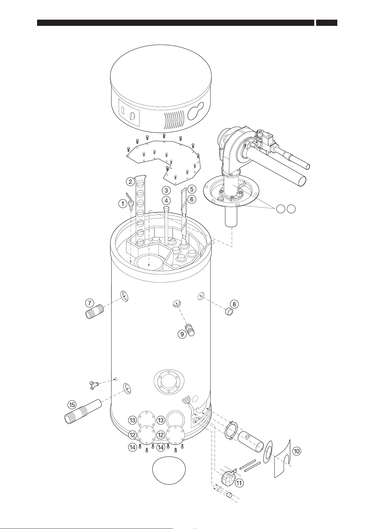
PARTS LIST AND ILLUSTRATIONS • SECTION 8
16 17
45
Page 46

SEC TIO N 8 • PARTS LIST AND ILLUSTRATIONS46PARTS LIST AND ILLUSTRATIONS • SECTION 8
COMBUSTION SURROUND ASSEMBLY
Part Ref. Description Part Number Qty
1 Ignition Control Assembly E885 1
2 Switch Main Power E884 1
3
Potentiometer E889 1
High Limit Thermostat E886
COMBUSTION ASSEMBLY
Part Ref. Description Part Number Qty
4 Blower – EBM 600/700/740 E892 1
5 Blower – EBM 960/980/1220/1400 E893 1
5A Fan Assembly 1900 Z040 1
6
Gasket & Screw E898 1
7 Gas Valve 600 E894 1
8 Gas Valve 700/740/960/980 E895 1
9 Gas Valve 1220 E896 1
10 Gas Valve 1400 E897 1
10A Gas valve 1900 G125 1
11 Gasket Flame Sensor E891 1
12 Flame Sensor E890 1
13 Hot Surface Ignitor E877 1
14 Burner Mounting Gasket E882 1
14A Blower Transition Gasket Z082 1
LPG Gas Valve 600 E901 1
LPG Gas Valve 700/740/960/980 E902 1
LPG Gas Valve 1220 E903 1
LPG Gas Valve 1400 E904 1
LPG Gas Orifice 600 E905 1
LPG Gas Orifice 700/740/960/980 E906 1
LPG Gas Orifice 1220 E907 1
LPG Gas Orifice 1400 E908 1
14B Burner Gasket G168 1
IGNITION CONTROL ASSEMBLY
Part Ref. Description Part Number Qty
15 Electronics Control Module E887 1
16 Transformer – 120/24 VAC E888 1
LPG GAS VALVE & FAN ASSEMBLY
Part Ref. Description Part Number Qty
18 LPG gas valve & fan assembly (Model no 230/600) Z084 1
18 LPG gas valve & fan assembly (Model no 230/700, 380/740) Z085 1
18 LPG gas valve & fan assembly (Model no 230/960, 380/980) Z086 1
18 LPG gas valve & fan assembly (Model no 380/1220) Z087 1
18 LPG gas valve & fan assembly (Model no 380/1400) Z088 1
18 LPG gas valve & fan assembly (Model no 380/1900) Z089 1
Page 47
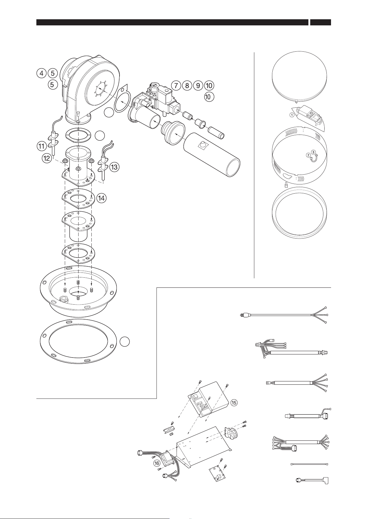
6
A
A
A
14
B
14
Combustion
assembly
47
Combustion
surround
assembly
Ignition
control
assembly
Page 48

48
SEC TIO N 8 • PARTS LIST AND ILLUSTRATIONS
ECOflo Concentric Flue Component List (100/150mm dia.)
Part Ref. Description Part Number
1 90° Elbow with Clamp E205
2 1000mm Flue with Clamp E202
3 Horizontal Flue Terminal E236
4 Wall Clamp (not shown) E209
5
1000mm Cutable Flue with Clamp E203
6 500mm Flue with Clamp E204
7 Condensate Trap Tee E210
8 Flat Roof Plate E207
9 Angled Roof Plate E208
10 Horizontal Flue Outlet Terminal Guard E105
11 45° Elbow with Clamp E206
Note: Extra lengths of flue and elbows can be supplied to suit each installation requirement.
Page 49
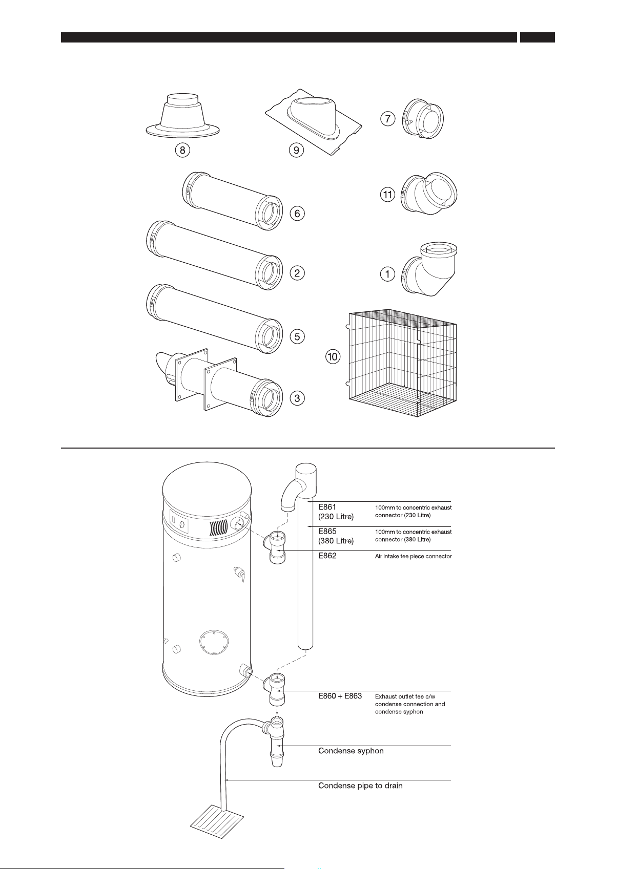
PARTS LIST AND ILLUSTRATIONS • SECTION 8
49
Page 50

50
SEC TIO N 8 • PARTS LIST AND ILLUSTRATIONS
ECOflo Unvented System Kit B290 – Parts List
art ref. Part Number Description Qty
P
C1 C784 Combined Pressure Reducing Valve/Strainer 1
C2 C785 Check Valve Assembly 1
C3 C786 Expansion Valve 1
C4 C782 Expansion Vessel (25 Litre) 1
C5 C380 Temperature/Pressure Relief Valve 1” 1
C6 C384 Tundish from Expansion Valve and T/P Valve 1
B173 Expansion Vessel Wall Mounting Kit (Optional)
C7 C788 Hose Assembly 1
8 C787 Wall Bracket Assembly 1
C
N/A E923 Plinth 150mm
Page 51
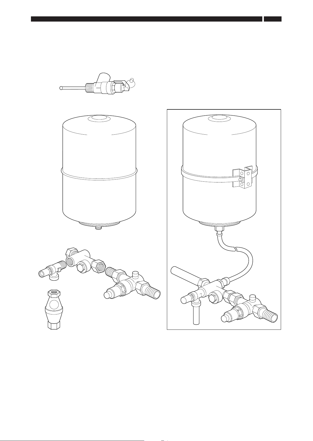
C6
C3
C2
C1
C4
C5
C8
C7
Unvented system kit components
PARTS LIST AND ILLUSTRATIONS • SECTION 8
51
Page 52

” R R hRjjmso
Baxi Commercial Division
Wood Lane, Erdington,
Birmingham B24 9QP
Publication Date: SEPT2012
Sales:
0845 070 1056
Email: [email protected]
www.andrewswaterheaters.co.uk
Technical:
0845 070 1057
 Loading...