


Instruction
Manual ANDERSON
Anderson Instrument Co., Inc.
156 Auriesville Rd.
Fultonville, NY 12072
Phone: 518-922-5315
800-833-0081
Fax: 518-922-8997
AV-9000 Recorder/
Rev. G |
Recording Controller |
|
Doc. AIC-3677
AV-9000 Manual Revision Log
|
Revision |
|
Date |
Description |
|
|
|
|
|
|
|
|
Edition 1 |
|
6/16/95 |
Released |
|
|
Edition 1 |
Rev A |
7/14/95 |
Revised Pages: 4,5, 1-1 thru 1-5, 2-8, 4-3, 4-5, |
|
|
|
|
|
4-6, 4-9 thru 4-11, 4-17, 4-37, 4-39, 4-40, 4-42, |
|
|
|
|
|
4-48, 4-50, 4-57, 4-100, 4-101, 7-1 thru 7-3, 10-1, |
|
|
|
|
|
11-1, C-2, C-3, C-5 thru C-7, C-10, C-11, C-13; |
|
|
|
|
|
Added Pages: D-1 thru D-4 and E-1 thru E-2. |
|
|
Edition 1 |
Rev B |
8/10/95 |
Revised Pages: 2-9 thru 2-13, 3-16, 4-13, 4-29, |
|
|
|
|
|
11-2 thru 11-7, B-1 thru B-2, C-4, C-10 and E-1 |
|
|
|
|
|
thru E-3. |
|
|
|
|
|
|
|
|
Edition 1 |
Rev C |
11/6/95 |
Revised Pages: 5, 1-3, 1-5, 2-6, 2-15, 3-5, 3-6, |
|
|
|
|
|
3-35, 4-8, 4-17, 4-26, 4-45, 4-79 thru 4-101, 6-9 |
|
|
|
|
|
thru 6-14, 8-1, 10-1 thru 10-2, 11-4, 11-6, A-1, A- |
|
|
|
|
|
4, E-1 thru E-3; |
|
|
|
|
|
Added Pages: 10-3 thru 10-5, 11-7 thru 11-8, A-6 |
|
|
|
|
|
thru A-7, D-7; |
|
|
|
|
|
Deleted Pages: 4-102. |
|
|
|
|
|
|
|
|
Edition 1 |
Rev D |
4/15/96 |
Revised Pages: 1,3,5, 1-3 thru 1-6, 2-1, 2-3, 2-4, |
|
|
|
|
|
2-6, 2-8, 2-15, 2-16, 3-3 thru 3-8, 3-10, 3-11, 3-19 |
|
|
|
|
|
thru 3-21, 3-24, 3-28, 3-29, 3-36 thru 3-39, 4-1 |
|
|
|
|
|
thru 4-3, 4-6 thru 4-13, 4-15, 4-17, 4-18, 4-23, |
|
|
|
|
|
4-24, 4-26, 4-30, 4-31, 3-35, 4-58, 4-59, 4-62, |
|
|
|
|
|
4-63, 4-65 thru 4-67, 4-71, 4-73, 4-74, 4-77 thru |
|
|
|
|
|
4-99, 5-2, 6-1, 6-6, 6-12, 6-13, 8-4, 9-3 thru 9-8, |
|
|
|
|
|
10-4, 11-5, thru 11-8, A-2, B-2, E-2. |
|
|
|
|
|
Added Pages: 8-5, 9-7, 9-8, A-8. |
|
|
|
|
|
Deleted Pages: 4-100, 4-101. |
|
|
|
|
|
|
|
|
Edition 1 |
Rev E |
9/18/96 |
Revised Pages: 1, 2-2, 4-23 thru 4-24, 4-58 thru |
|
|
|
|
|
4-59, 4-63, 4-65, 4-67, 4-73 thru 4-74, 4-80, 4-87, |
|
|
|
|
|
4-91, 4-95 thru 4-96, 11-1 thru 11-4, C5, C14, |
|
|
|
|
|
D-3. |
|
|
|
|
|
|
|
|
Edition 2 |
Rev F |
4/1/97 |
Revised Pages: 1-1, 1-3, 1-4, 1-5, 2-16, 3-13, |
|
|
|
|
|
3-16,3-17, 3-23, 3-29, 3-33, 3-44, 4-2, 4-17, 4-20, |
|
|
|
|
|
4-21, 4-22, 4-23, 4-24, 4-34, 4-36, 4-38, 4-39, |
|
|
|
|
|
4-41,4-42, 4-45, 4-54, 4-58, 4-59, 4-63, 4-65, |
|
|
|
|
|
4-66, 4-67, 4-68, 4-69, 4-73, 4-74, 4-75, 4-77, |
|
|
|
|
|
4-78, 4-80, 4-87, 4-91, 4-93, 4-94, 5-1, 6-6, 6-12, |
|
|
|
|
|
6-13, 8-2, 8-3, 8-4, 8-5, 9-2, 9-6. |
|
|
|
|
|
Added Pages: 3-24, 3-25, 3-36, 3-37, 3-43, SEC13 |
|
|
|
|
|
|
|
|
Edition 3 |
Rev G |
7/1/98 |
Revised Pages: 9-2 thru 9-22 |
|
|
|
|
|
Added Pages: SEC 14 |
|
|
|
|
|
|
|
|
|
|
|
|
|
Prefix & Table of Contents |
1 |
Edition 3 |
|
|
Rev G |

AV-9000 Manual Prefix
MANUAL ORGANIZATION
This manual is organized in twelve major sections:
Section 1 |
Introduction and General Information |
Section 2 |
Installation and Wiring |
Section 3 |
The Basics of Recorder Operation |
Section 4 |
Configuration |
Section 5 |
Display Programming |
Section 6 |
Chart Prompts |
Section 7 |
Alarm Settings |
Section 8 |
Action Time Settings |
Section 9 |
Enables & Passwords |
Section 10 |
Test |
Section 11 |
Calibration |
Section 12 |
Appendix |
Section 13 |
Controllers |
Section 14 |
Profilers |
All users should be familiar with the first three sections of this manual before beginning to operate the recorder.
Operators are then advised to cover the Display Programming, Chart Prompts and Alarm Setting sections. Configurators should be familiar with all information, particularly the details in the Configuration Programming section.
ANDERSON TECHNICAL AND APPLICATION SUPPORT
Please have your recorder model number AND serial number available before calling for technical and application support. Support is available from:
The Anderson Instrument Company, Inc.
156 Auriesville Road
Fultonville, New York 12072
1-800-833-0081 or 1-518-922-5315 Fax: 1-800-726-6733 or 1-518-922-8997
Prefix & Table of Contents |
2 |
Edition 3 |
|
|
Rev G |

Table of Contents
|
|
|
PAGE |
SECTION 1 - INTRODUCTION AND GENERAL INFORMATION |
1-1 |
||
1.1 |
Unpacking |
|
1-1 |
1.2 |
Installation of Pen Cartridge Assembly |
1-2 |
|
1.3 |
Order Matrix/Model Number |
1-3 |
|
1.4 |
Specifications |
1-4 |
|
1.5 |
Warranty Statement |
1-7 |
|
SECTION 2 - INSTALLATION AND WIRING |
2-1 |
||
2.1 |
Mounting |
|
2-1 |
2.2 |
Preparation for Wiring |
2-3 |
|
2.3 |
Wiring Connections - Inputs |
2-6 |
|
|
2.3.1 |
Shipped Configuration/Jumper Positioning |
2-7 |
|
2.3.2 |
Sensor Break |
2-7 |
|
2.3.2 |
AC Power Connections |
2-8 |
|
2.3.4 |
Thermocouple Connections |
2-9 |
|
2.3.5 |
RTD Connections |
2-10 |
|
2.3.6 |
Voltage Connections |
2-11 |
|
2.3.7 |
Current Connections |
2-12 |
|
2.3.8 |
Switch Input Connections |
2-13 |
2.4 |
Wiring Connections - Outputs |
2-14 |
|
|
2.4.1 |
SPDT Relay |
2-14 |
|
2.4.2 |
Solid State Relay Driver (SSRD) |
2.14 |
|
2.4.3 |
Current Output |
2-15 |
|
2.4.4 |
24 VDC Transmitter Power Supply |
2-15 |
|
2.4.5 |
Communications |
2-16 |
SECTION 3 - THE BASICS OF RECORDER OPERATION |
3-1 |
||
3.1 |
Power Up |
|
3-1 |
3.2 |
Instrument Modes |
3-1 |
|
|
3.2.1 |
Normal Display |
3-1 |
|
3.2.2 |
Display Prompts |
3-1 |
|
3.2.3 |
Chart Prompts |
3-1 |
|
3.2.4 |
System Prompts |
3-1 |
3.3 |
Keypad Functions |
3-2 |
|
|
3.3.1 |
DISPLAY key |
3-2 |
|
3.3.2 |
CHART key |
3-2 |
|
3.3.3 |
SCROLL key |
3-2 |
|
3.3.4 |
ARROW key |
3-2 |
|
3.3.5 |
RESET key |
3-2 |
|
3.3.6 |
ESCAPE key, MODIFY key, ENTER key |
3-2 |
|
3.3.7 |
Special keys |
3-2 |
3.4 |
Changing Parameter Setting - Modify |
3-3 |
|
|
3.4.1 |
Changing Values |
3-3 |
|
3.4.2 |
Changing Text |
3-3 |
|
3.4.3 |
Changing Choices |
3-3 |
|
3.4.4 |
Copy/Initialize |
3-4 |
|
3.4.5 |
Passwords |
3-4 |
|
3.4.6 |
Enables |
3-4 |
3.5 |
The Display |
3-4 |
|
3.6 |
General |
|
3-4 |
3.7 |
Display Details |
3-5 |
|
3.8 |
Chart Details |
3-7 |
|
|
|
|
|
Prefix & Table of Contents |
3 |
Edition 3 |
|
|
Rev G |

|
|
|
PAGE |
|
3.8.1 |
Chart Printing Interruptions |
3-8 |
|
3.8.2 |
New Chart Printing Requirements |
3-9 |
|
3.8.3 |
Example Chart |
3-9 |
|
3.8.4 |
Sequence of Events |
3-12 |
3.9 |
Getting Started |
3-13 |
|
3.10 |
Quick Start Procedure |
3-14 |
|
SECTION 4 - CONFIGURATION |
4-1 |
||
4.1 |
Entering Configuration |
4-1 |
|
|
4.1.1 |
Inputs |
4-1 |
|
4.1.2 |
Constants |
4-14 |
|
4.1.3 |
Custom Curves |
4-15 |
|
4.1.4 |
Derived Variables |
4-18 |
|
4.1.5 |
Process Variables |
4-32 |
|
4.1.6 |
Recorders |
4-43 |
|
4.1.7 |
Totalizers |
4-52 |
|
4.1.8 |
Timers |
4-61 |
|
4.1.9 |
LEDs |
4-64 |
|
4.1.10 |
Relays |
4-66 |
|
4.1.11 |
Current Outputs |
4-69 |
|
4.1.12 |
Instrument Settings |
4-72 |
|
4.1.13 |
Derived Actuators |
4-78 |
|
4.1.14 |
Operator Inputs |
4-81 |
|
4.1.15 |
Operator Messages |
4-85 |
|
4.1.16 |
Chart Messages |
4-89 |
|
4.1.17 |
Simulated Variables |
4-95 |
SECTION 5 - DISPLAY PROGRAMMING |
5-1 |
||
SECTION 6 - CHART PROMPTS |
6-1 |
||
6.1 |
Change Chart |
6-1 |
|
6.2 |
Chart Configuration |
6-2 |
|
SECTION 7 - ALARM SETTINGS |
7-1 |
||
SECTION 8 - ACTION TIME SETTINGS |
8-1 |
||
SECTION 9 - ENABLES & PASSWORDS |
9-1 |
||
SECTION 10 - TEST |
10-1 |
||
SECTION 11 - CALIBRATION |
11-1 |
||
SECTION 12 - APPENDIX |
|
||
|
A - Board Layouts |
A-1 |
|
|
B - Ranges |
B-1 |
|
|
C - Reference |
C-1 |
|
|
D - Examples |
D-1 |
|
|
E - Accuracy Tables |
E-1 |
|
Prefix & Table of Contents |
4 |
Edition 3 |
|
|
Rev G |

|
|
PAGE |
SECTION 13 - CONTROLLERS |
13-1 |
|
13.1 |
Entering Controllers |
13-3 |
13.2 |
Control Setpoints |
13-18 |
13.3 |
Control State Access |
13-22 |
13.4 |
Tuning Parameters |
13-31 |
SECTION 14 - PROFILERS |
14-1 |
|
14.1 |
Profile Entry |
14-1 |
14.2 |
Profile Settings |
14-4 |
14.3 |
Profile Control |
14-7 |
Figures and Tables
Figure 1-1 |
Pen Cartridge Installation |
1-2 |
Figure 2-1A |
Mounting Dimensions |
2-1 |
Figure 2-1B |
Dimensional Drawing |
2-2 |
Figure 2-2 |
Noise Suppression |
2-4 |
Figure 2-3 |
Noise Suppression |
2-4 |
Figure 2-4 |
Board and Terminal Locations |
2-6 |
Figure 2-5 |
Shipped Jumper Positions |
2-7 |
Figure 2-6A |
AC Power Connections, 115/230 |
2-8 |
Figure 2-6B |
AC Power Connection, Universal |
2-8 |
Figure 2-7 |
TC Connections |
2-9 |
Figure 2-8 |
RTD Connections |
2-10 |
Figure 2-9 |
Voltage Connections |
2-11 |
Figure 2-10 |
Current Connections |
2-12 |
Figure 2-11 |
Switch Input Connections |
2-13 |
Figure 2-12 |
SPDT Relay Output |
2-14 |
Figure 2-13 |
SSR Driver Ouptut |
2-14 |
Figure 2-14 |
Current Output |
2-15 |
Figure 2-15 |
Transmitter Power Supply |
2-15 |
Figure 2-16 |
RS-485 Communications |
2-16 |
Figure 2-17 |
RS-232 Communications |
2-16 |
Figure 3-1 |
Keypad |
3-2 |
Figure 3-2 |
Example Chart |
3-12 |
Figure 11-1 |
Jumper Positions for Calibration |
11-3 |
Figure A-1 |
Power Supply Board |
A-1 |
Figure A-2 |
Mother Board |
A-2 |
Figure A-3 |
Relay/SSR Board |
A-3 |
Figure A-4 |
Input Board |
A-4 |
Figure A-5 |
Motor Driver Board |
A-5 |
Figure A-6 |
Current Ouptut Board |
A-6 |
Figure A-7 |
Transmitter Power Supply |
A-7 |
Figure A-8 |
Communication Board |
A-8 |
Table 2-1 |
Board ID Jumpers |
2-7 |
Table 3-1 |
Configure Chart Parameters |
3-10 |
Table 3-2 |
Recorder Parameters |
10-1 |
Table 10-1 |
Available Tests |
10-1 |
Table 11-1 |
Calibration Routines |
11-1 |
Table 11-2 |
Range Select |
11-2 |
Table 11-3 |
Input Board Jumper Positions |
11-3 |
Prefix & Table of Contents |
5 |
Edition 3 |
|
|
Rev G |

Section 1 - Introduction and General Information
This instrument is a microprocessor based circular chart recorder capable of measuring, displaying, and recording from a variety of inputs. Applications include temperature, level, pressure, flow, and others. The instrument can be specified as either a one, two, three, or four pen model.
The standard process sensor inputs (up to 8 total inputs) are user configurable to directly connect to and convert thermocouple, RTD, millivolt, volt, milliamp or contact closure inputs. Thermocouple and RTD linearization, as well as thermocouple cold junction compensation, are performed automatically. Up to four individually isolated 24 VDC regulated transmitter power supplies are available for transmitter inputs, each providing up to 25 mADC.
Using the optional math capability, mass flow, BTUs, relative humidity, and other derived variables can be calculated, as well as simple math functions performed and custom curve conversions. Optional totalization is available for input values or derived variables. Any recorder value can be treated as a process value, to provide alarming and special display capability.
Up to 4 variables can be recorded as analog trend lines on chart sizes of 10, 11, or 12 inches in diameter. The trend lines can be the result of instantaneous values, connecting the values, drag pen, average values, or connecting the average values. The trend lines can be scaled and positioned on the chart in zones. Trend scales, units, and a trend tag can be printed in the same color as time lines.
Dates, times, batch numbers, operator IDs, process values, scales and alarm messages can all be printed on the chart in color.
Definitions for a large number of "Terms and Concepts" described in this manual are included in Appendix C.
1.1 UNPACKING
Remove the instrument and pen cartridge assembly from the shipping container and inspect for any damage due to shipment. If any damage is noticed due to transit, report and file a claim with the carrier. Write the model number and serial number in spaces provided on Page 1-3 of this manual for future reference. The model number and serial number are found on the label on the case, viewed when platen is open.
!
CAUTION: READ THIS MANUAL
THE INTERNATIONAL HAZARD SYMBOL IS FOUND ADJACENT TO THE LOWER PLATEN HOLD DOWN SCREW. IT IS IMPORTANT TO READ THIS MANUAL BEFORE INSTALLING OR COMMISSIONING THE UNIT.
Section 1 |
1-1 |
Edition 3 |
Rev G

1.2 INSTALLATION OF PEN CARTRIDGE ASSEMBLY
Remove the pen cartridge assembly from its shipping container. With mounting tab on the bottom, slide the pen cartridge assembly (item 2 on Figure 1-1) into the print actuator (item 1 on Figure 1-1).
FIGURE 1-1
PLASTIC CHART SHIELD (DO NOT REMOVE)
INSTALL PEN
CARTRIDGE (2)
PRINT ACTUATOR
TRAVERSE CABLE
PRINT ACTUATOR (1)
1 |
2 |
3 |
4 |
5 |
6 |
7 |
8 |
Edition 3 |
1-2 |
Section 1 |
Rev G
1.3 ORDER MATRIX / MODEL NUMBER
|
|
|
|
|
|
AV- |
9 |
|
|
|
|
|
|
|
|
|
|
0 |
|
|
|
|
0 |
|
|
|
|
|
|
|
0 |
3 |
|
3 |
|
|
||||
|
TYPE |
|
|
|
|
|
|
|
|
|
|
|
|
|
|
|
|
|
|
|
|
|
|
|
|
|
|
|
|
|
|
|
|
|
|
|
|
|
CASE TYPE & MOUNTING |
|
|
|
|
|
|
|
|
|
|
|
|
|
|
|
|
|
|
|
|
|
|
|
|
|
|
|
|
|
|
|
|
|
|
|
|
|
|
|
|||
|
|
|
|
|
|
|
|
|
|
|
|
|
|
|
|
|
|
|
|
|
|
|
|
|
|
|
|
|
|
|
|
|
|
|
|
|
|
|||
1 |
Recorder Only |
|
|
|
|
|
|
|
|
|
|
|
|
|
|
|
|
|
|
|
3 |
|
|
|
NEMA4X Wall/Panel Mount |
|||||||||||||||
2 |
Recorder/Controller |
|
|
|
|
|
|
|
|
|
|
|
|
|
|
|
|
|
|
|
|
|
|
|
|
|
|
|
|
|
|
|
||||||||
|
PENS/COLORS |
|
|
|
|
|
|
|
|
|
|
|
|
|
|
|
|
|
|
|
|
|
|
|
|
|
|
|
|
|
|
|
|
|
|
|
|
ENCLOSURE OPTIONS |
||
|
|
|
|
|
|
|
|
|
|
|
|
|
|
|
|
|
|
|
|
|
|
|
|
|
|
|
|
|
|
|
|
|
|
|
|
|
||||
2 |
|
|
|
|
|
|
|
|
|
|
|
|
|
|
|
|
|
|
|
|
|
|
|
|
|
3 |
|
|
|
Plastic Window |
||||||||||
|
|
|
|
|
|
|
|
|
|
|
|
|
|
|
|
|
|
|
|
|
|
|||||||||||||||||||
Two Trend, Two Colors** |
|
|
|
|
|
|
|
|
|
|
|
|
|
|
|
|
|
|
|
|
|
|
|
|
|
|
|
|
|
|
|
|||||||||
4 |
Four Trend Pens, Four Colors |
|
|
|
|
|
|
|
|
|
|
|
|
|
|
|
|
|
|
|
|
|
|
|
|
|
|
|
|
|
MEMORY CARD/COMS |
|||||||||
|
|
|
|
|
|
|
|
|
|
|
|
|
|
|
|
|
|
|
|
|
|
|
|
|
|
|
|
|
||||||||||||
|
UNIVERSAL INPUTS |
|
|
|
|
|
|
|
|
|
|
|
|
|
|
|
|
|
|
|
|
|
0 |
|
|
|
None |
|||||||||||||
|
|
|
|
|
|
|
|
|
|
|
|
|
|
|
|
|
|
|
|
|
|
|
|
|
|
|
|
|
|
|
|
|
|
|
|
|||||
1 |
One Input |
|
|
|
|
|
|
|
|
|
|
|
|
|
|
|
|
|
|
|
|
|
|
|
|
|
|
|
|
|
MATH/TOTALIZER |
|||||||||
|
|
|
|
|
|
|
|
|
|
|
|
|
|
|
|
|
|
|
|
|
|
|
|
|
|
|
|
|
||||||||||||
2 |
Two Inputs |
|
|
|
|
|
|
|
|
|
|
|
|
|
|
|
|
0 |
|
|
|
None |
||||||||||||||||||
3 |
Three Inputs |
|
|
|
|
|
|
|
|
|
|
|
|
|
|
|
|
1 |
|
|
|
Math |
||||||||||||||||||
4 |
Four Inputs |
|
|
|
|
|
|
|
|
|
|
|
|
|
|
|
|
2 |
|
|
|
Totalizer |
||||||||||||||||||
6 |
Six Inputs |
|
|
|
|
|
|
|
|
|
|
|
|
|
|
|
|
3 |
|
|
|
Math & Totalizer |
||||||||||||||||||
8 |
Eight Inputs |
|
|
|
|
|
|
|
|
|
|
|
|
|
|
|
|
|
|
|
|
|
|
|
|
|
|
|
|
|
|
|
||||||||
0 |
FIXED CHARACTER |
|
|
|
|
|
|
|
|
|
|
|
|
|
|
|
|
|
|
|
|
|
|
|
|
|
|
|
|
|
|
|
|
|
|
24V TRANSMITTER POWER SUPPLY |
||||
|
|
|
|
|
|
|
|
|
|
|
|
|
|
|
|
|
|
|
|
|
|
|
|
|
|
|
|
|
|
|
|
|
|
|||||||
|
|
|
|
|
|
|
|
|
|
|
|
|
|
|
|
|
|
|
0 |
|
|
|
None |
|||||||||||||||||
|
|
|
|
|
|
|
|
|
|
|
|
|
|
|
|
|
|
|
||||||||||||||||||||||
|
RELAY OUTPUTS |
|
|
|
|
|
|
|
|
|
|
|
|
|
|
|
|
|
|
|
|
|
1 |
|
|
|
One Supply |
|||||||||||||
|
|
|
|
|
|
|
|
|
|
|
|
|
|
|
|
|
|
|
|
2 |
|
|
|
Two Supplies |
||||||||||||||||
0 |
None |
|
|
|
|
|
|
|
|
|
|
|
|
|
|
|
3 |
|
|
|
Three Supplies |
|||||||||||||||||||
2 |
Two Relays |
|
|
|
|
|
|
|
|
|
|
|
|
|
|
|
4 |
|
|
|
Four Supplies |
|||||||||||||||||||
4 |
Four Relays |
|
|
|
|
|
|
|
|
|
|
|
|
|
|
|
|
|
|
|
|
|
|
|
|
|
|
|
|
|
|
|
||||||||
6 |
Six Relays |
|
|
|
|
|
|
|
|
|
|
|
|
|
|
|
|
|
|
|
|
|
|
|
|
|
|
|
|
|
|
|
||||||||
8Eight Relays
0FIXED CHARACTER
|
4-20 mA OUTPUTS (isolated)* |
|
|
|
* |
One 4-20mA output |
|
|
|
|
|||
0 |
None |
|
|
|
required for each |
|
3 |
One 4-20 mA Output (int. pwr.) |
|
|
|
controller function |
|
4 |
Two 4-20 mA Outputs (int. pwr.) |
|
|
|
|
|
5 |
Three 4-20 mA Outputs (int. pwr.) |
|
|
** |
Pens/colors are added |
|
6 |
Four 4-20 mA Outputs (int. pwr.) |
|
|
|
to the instrument in the |
|
7 |
Two 4-20 mA Outputs (ext. pwr.) |
|
|
|
following order: red, |
|
8 |
Four 4-20 mA Outputs (ext. pwr.) |
|
|
|
then green, then blue, |
|
9 |
Four 4-20 mA Outputs (2-int. pwr./2-ext. pwr.) |
|
and then black. |
|||
NOTE: |
Additional charts may be ordered separately (100 per box) |
|
|
|||
|
12î/100 Rings |
#00215216 |
|
|
|
|
Warranty: The AV-9000 is backed by a comprehensive 2 year warranty.
Operation Manual: One operation manual is supplied with each unit.
Replacement Pen Cartridges
Part Number |
Pen Colors |
60500802 |
Green, Red |
60500803 |
Blue, Green, Red |
60500804 |
Blue, Green, Red, Black |
MODEL NUMBER
SERIAL NUMBER
Section 1 |
1-3 |
Edition 2 |
|
|
Rev F |

1.4 SPECIFICATIONS
DESCRIPTION
The instrument is the first circular chart recorder with the ability to record trend data and print alphanumeric in four colors. It uses unique ìring onlyî charts and has the ability to zone and scale trend data. These capabilities not only provide the best trend data readability, but also instant association with the corresponding scales. Whether itís basic application of recording inputs, to a demanding application requiring derived variables, logic functions, totalization, or other capabilities, the instrument can be supplied with the necessary level of sophistication, while maintaining an uncomplicated operator interface.
MODELS
The instrument is available in versions for trend recording of one to four values. The number of colors can equal the number of trended values, or all four colors can be provided. The latter option provides the greatest color flexibility and makes it easier to add trend capability to the instrument in the field. The instrument can have up to eight inputs, and inputs are not directly associated with trend pens. The instrument can trend any combination of inputs, averages, derived variables, logic states, even totals. A full compliment of options provides the flexibility to handle virtually any type of application.
FEATURES
ïColor Chart
ï1,2,3, and 4 trend pen versions
ïAll versions with optional four color capability
ï10", 11", or 12" charts
ïLinear scales and radial time lines
ïTrend zoning and dual zone capability
ïUp to 8 universal inputs
ï40 character, vacuum fluorescent display
ïSimultaneous display approach for flexibility
ïBuilding block approach for flexibility
ïMath and equations for actuators
ïLogic equations for actuators
ï9 digit totalizes
ïChart messages
ïOperator inputs
ïOperator messages
ïReal time clock
ïTime and date printed on charts
CONFIGURATION
A multilevel prompting scheme provides rapid access to all configuration data. By model number and
selective enabling the software displays only those configuration sections needed. The 40 character, vacuum fluorescent display provides true English language prompts. The 15 keypad makes moving through the prompts and modifying the parameters intuitive. Multiple choice selections and use of the ìquick select keysî simplifies the programming of many parameters. Copy functions make configuring similar sets of parameters even faster. Two methods of modifying character strings simplifies the entry of English tags and units. The instrument even displays the proper jumper placement for the installer. The instrument can virtually be configured without looking at the manual.
Section 1 |
1-4 |
Edition 2 |
|
|
Rev F |

OPERATOR INTERFACE
Beyond the configuration capability, the display, keypad, and prompting system provide superior real time data presentation. The display of each instrument value is configurable and three display formats are available, providing a range from fully detailed displays with 20 character tags, alarm indications, values, and units, to four process values displayed simultaneously. Separate keys are used to access the display, chart, and configuration related areas. By selective enabling and password protection, access to various operational areas of the instrument can be limited or controlled. Some keys can also be configured to provide special functions, such as resetting totalizers. The operator interface has been designed to make daily operation as simple as possible. Changing charts, for example, requires only three keystrokes.
CONSTRUCTION
The instrument is housed in a structural foam moulded enclosure which can be panel or surface mounted. Mounting brackets are included. Its design allows it to fit into the smallest panel cutout of competitive products, while it covers the largest cutout of others. Glass and plastic windows are available, along with a cover lock. The standard enclosure carries a NEMA3 rating, with an optional NEMA4X available.
OPTIONS
The instrument is available with a full compliment of options. Up to eight isolated universal inputs are available with each being configurable to any of the available input types. Up to four isolated transmitter power supplies can be added. Up to four inputs or derived variables can be assigned as "process variables", allowing up to four alarms for each. Alarms can be process high or low, or rate rising or falling. The alarming capability is standard, but the hardware outputs are optional. Up to eight on/off outputs are available, either relay or solid state relay driver outputs. Besides alarms, any of over eighty other digital values/ states can be used to actuate on/off outputs. Up to two non-isolated analog outputs or up to 4 isolated analog outputs are available. Any of over twenty values can be used to drive analog outputs (i.e. inputs, derived variables, etc.) Other options include PC based configuration software and a communications interface.
FIELD UPGRADES
All of items listed in the Options section are easily installed in the field. Typically it involves just adding boards, but possibly PROMs may need to be changed as well. To add totalizers or the math package, only PROMS must be changed. If the four color option was purchased, only PROMS need to be changed to expand trend capability, otherwise, a relative costly pen arm assembly must be replaced as well.
Section 1 |
1-5 |
Edition 3 |
Rev G

INPUTS
Input Types |
|
Thermocouple |
Types J, K, T, R, S, E, B, N, G, D, C, Ni/Ni-Moly, and Platinel II. |
RTD |
Platinum 100, 2 or 3 wire |
|
.00385 coefficient DIN 43760/IEC 751 |
|
.00392 coefficient USA |
|
.00392 coefficient SAMA |
|
Nickel 100, 2 or 3 wire |
Voltage DC |
0 to 25mV, 0 to 100 mVDC, 0 to 1 VDC, 0 to 10 VDC |
Current DC |
0 to 20mA, 4 to 20mA |
|
Internal 50 ohm shunt resistor |
Contact Closure |
Open/closed switch sensing without external voltages or resistors |
Impedance |
25mV, 100mV, 1 Volt: > 10 meg ohms |
|
10 Volt: > 50 K ohms |
|
mA: 50 ohms |
RTD Excitation Current |
1 mA |
INPUT PERFORMANCE
Measurement Error |
± .025% of measurement span reference accuracy |
Cold Junction Compensation Error |
± 0.2°C @ 25 degrees C |
Cold Junction Compensation Rejection |
0.04°/degree C deviation from 25 degrees C |
Linearization Error |
TCs: ± 0 .25°C typical, ± 0.5°C worst case with exceptions |
|
RTDs: ± 0.1°C typical, ± 0.3°C worst case |
Ambient Temperature Error |
± 0 .01% of span per degree C deviation from 25 degrees C |
Factory Calibration Error |
Refer to the Accuracy Table |
Isolation |
500 VDC/350 VAC |
Common Mode Rejection |
120 dB min. |
Normal Mode Rejection |
100 dB min. @ 60 Hz or greater |
Scan Rate |
The input scan rate is programmable and dependant on the number of active |
|
inputs present. The total scans per second for the instrument is 16 scans/ |
|
second, and the instrument can have up to 8 inputs configured. |
Edition 3 |
1-6 |
Section 1 |
Rev G

ACCURACY TABLES
|
See Note: |
1 |
2 |
3 |
4 |
5 |
6 |
|
TC |
RANGE |
REF |
LIN. |
FACTORY |
REF+LIN |
DEVIATION |
RESOL |
|
TYPE |
°C |
ACC'Y |
ACC'Y |
CAL |
+CAL |
ACC'Y |
°C/bit |
|
|
°C |
°C |
°C |
°C |
°C |
|||
|
|
|
|
|
|
|
|
|
J |
0/1200 |
0.43 |
0.20 |
0.32 |
0.95 |
0.12 |
0.066 |
|
WIDE |
-200/0 |
0.63 |
0.08 |
0.56 |
1.28 |
0.02 |
0.097 |
|
J |
0/400 |
0.11 |
0.05 |
0.33 |
0.50 |
0.04 |
0.017 |
|
NARROW |
-200/0 |
0.16 |
0.08 |
0.56 |
0.80 |
0.02 |
0.024 |
|
K |
0/1370 |
0.62 |
0.26 |
0.40 |
1.28 |
0.14 |
0.095 |
|
WIDE |
-250/0 |
1.05 |
0.30 |
0.78 |
2.13 |
0.03 |
0.159 |
|
K |
0/500 |
0.15 |
0.08 |
0.39 |
0.62 |
0.05 |
0.023 |
|
NARROW |
-250/0 |
0.26 |
0.30 |
0.78 |
1.35 |
0.03 |
0.040 |
|
E |
0/1000 |
0.33 |
0.19 |
0.28 |
0.80 |
0.10 |
0.050 |
|
WIDE |
-250/0 |
0.66 |
0.42 |
0.62 |
1.71 |
0.03 |
0.101 |
|
E |
0/300 |
0.09 |
0.19 |
0.29 |
0.57 |
0.03 |
0.014 |
|
NARROW |
-250/0 |
0.17 |
0.42 |
0.62 |
1.21 |
0.03 |
0.025 |
|
N |
0/1300 |
0.68 |
0.21 |
0.42 |
1.32 |
0.13 |
0.104 |
|
WIDE |
-250/0 |
1.44 |
0.60 |
0.93 |
2.97 |
0.03 |
0.220 |
|
N |
0/600 |
0.18 |
0.11 |
0.44 |
0.73 |
0.06 |
0.028 |
|
NARROW |
-200/0 |
0.31 |
0.20 |
0.81 |
1.32 |
0.02 |
0.048 |
|
|
-250/-200 |
0.93 |
0.60 |
2.15 |
3.68 |
0.01 |
0.142 |
|
|
|
|
|
|
|
|
|
|
To achieve stated results, the following thermocouples must be used with the INPUT TYPE/RANGE set to TC NARROW
G |
1800/2300 |
|
1.59 |
0.54 |
0.79 |
2.92 |
0.05 |
0.243 |
|
||||||||
|
800/1800 |
|
1.23 |
0.43 |
0.64 |
2.30 |
0.10 |
0.188 |
|
500/800 |
|
1.38 |
0.25 |
0.70 |
2.33 |
0.03 |
0.210 |
|
300/500 |
|
1.79 |
0.25 |
0.87 |
2.91 |
0.02 |
0.274 |
|
0/300 |
|
3.65 |
0.58 |
1.61 |
5.84 |
0.03 |
0.557 |
C |
1800/2300 |
|
2.14 |
0.54 |
1.01 |
3.68 |
0.05 |
0.326 |
|
1200/1800 |
|
1.62 |
0.43 |
0.80 |
2.85 |
0.06 |
0.247 |
|
300/1200 |
|
1.33 |
0.28 |
0.68 |
2.29 |
0.09 |
0.202 |
|
0/300 |
|
1.54 |
0.12 |
0.77 |
2.43 |
0.03 |
0.235 |
D |
1800/2300 |
|
1.88 |
0.38 |
0.90 |
3.26 |
0.05 |
0.287 |
|
300/1800 |
|
1.32 |
0.40 |
0.68 |
2.40 |
0.15 |
0.201 |
|
0/300 |
|
1.75 |
0.26 |
0.85 |
2.86 |
0.03 |
0.267 |
NNM |
450/1370 |
|
0.44 |
0.33 |
0.33 |
1.10 |
0.09 |
0.067 |
|
0/450 |
|
0.56 |
0.13 |
0.37 |
1.06 |
0.05 |
0.085 |
Platinel II |
1000/1400 |
|
0.72 |
0.28 |
0.44 |
1.44 |
0.04 |
0.110 |
|
500/1000 |
|
0.59 |
0.20 |
0.38 |
1.17 |
0.05 |
0.089 |
|
0/500 |
|
0.62 |
0.10 |
0.40 |
1.12 |
0.05 |
0.095 |
|
|
|
|
|
|
|
|
|
Section 1 |
1-7 |
Edition 3 |
Rev G

ACCURACY TABLES CONT.
To achieve stated results, the following thermocouples must be used with the INPUT TYPE/RANGE set to TC NARROW
|
See Note: |
1 |
2 |
3 |
4 |
5 |
6 |
TC |
RANGE |
REF |
LIN. |
FACTORY |
REF+LIN |
DEVIATION |
RESOL |
TYPE |
°C |
ACC'Y |
ACC'Y |
CAL |
+CAL |
ACC'Y |
°C/bit |
|
°C |
°C |
°C |
°C |
°C |
||
T |
0/400 |
0.12 |
0.09 |
0.34 |
0.55 |
0.04 |
0.018 |
|
-200/0 |
0.23 |
0.19 |
0.70 |
1.12 |
0.02 |
0.036 |
|
-250/-220 |
0.73 |
0.36 |
1.90 |
2.98 |
0.00 |
0.111 |
R |
800/1700 |
0.43 |
0.19 |
0.83 |
1.45 |
0.09 |
0.065 |
|
200/800 |
0.58 |
0.25 |
1.08 |
1.90 |
0.06 |
0.088 |
S |
250/1750 |
0.56 |
0.25 |
1.05 |
1.87 |
0.15 |
0.086 |
B |
200/1800 |
0.74 |
0.31 |
1.34 |
2.39 |
0.16 |
0.113 |
|
|
|
|
|
|
|
|
|
See Note: |
1 |
2 |
3 |
4 |
5 |
6 |
RTD |
RANGE |
REF |
LIN. |
FACTORY |
REF+LIN |
DEVIATION |
RESOL |
TYPE |
°C |
ACC'Y |
ACC'Y |
CAL |
+CAL |
ACC'Y |
°C/bit |
|
°C |
°C |
°C |
°C |
°C |
||
385 |
-160/480 |
0.16 |
0.03 |
0.13 |
0.33 |
0.06 |
0.025 |
DIN |
-200/-160 |
0.14 |
0.20 |
0.12 |
0.46 |
0.00 |
0.022 |
392 |
-100/450 |
0.16 |
0.03 |
0.13 |
0.32 |
0.05 |
0.025 |
USA |
|
|
|
|
|
|
|
392 |
-200/560 |
0.29 |
0.13 |
0.24 |
0.66 |
0.06 |
0.044 |
SAMA |
|
|
|
|
|
|
|
100 ohm |
-40/200 |
0.09 |
0.05 |
0.07 |
0.21 |
0.02 |
0.013 |
Nickel |
|
|
|
|
|
|
|
|
|
|
|
|
|
|
|
Edition 3 |
1-8 |
Section 1 |
Rev G

ACCURACY TABLES CONT.
|
|
|
See Note: |
1 |
3 |
4 |
|
5 |
6 |
||
|
|
|
|||||||||
|
INPUT |
|
SPAN |
REF |
FACTORY |
REF+LIN |
|
|
DEVIATION |
RESOL |
|
|
TYPE |
|
|
|
ACC'Y |
CAL |
+CAL |
|
|
ACC'Y |
°C/bit |
|
|
|
mV |
uV |
uV |
uV |
|
|
uV |
||
|
|
|
|
|
|
|
|
|
|
|
|
|
10V |
0/10000 |
|
2500 |
1000 |
3500 |
|
1000 |
381 |
||
|
1V |
0/1000 |
|
250 |
100 |
350 |
|
100.0 |
38.1 |
||
|
100mV |
0/100 |
|
25 |
20 |
45 |
|
10.0 |
3.81 |
||
|
25mV |
0/25 |
|
6 |
20 |
26 |
|
2.5 |
0.954 |
||
|
|
|
|
|
|
|
|
|
|
|
|
|
|
|
See Note: |
1 |
3 |
4 |
5 |
6 |
|||
|
INPUT |
|
SPAN |
|
REF. |
FACTORY |
REF+CAL |
|
|
DEVIATION |
RESOL. |
|
TYPE |
|
|
|
ACC'Y |
CAL |
|
|
|
ACC'Y |
|
|
|
|
mA |
|
uA |
uA |
uA |
|
|
uA/°C |
uA/bit |
|
mA |
|
4/20 |
|
5 |
2 |
7 |
|
2.0 |
0.763 |
|
|
|
|
0/20 |
|
5 |
2 |
7 |
|
2.0 |
0.763 |
|
NOTES: The table attempts to show the effect of each significant factor which contributes to the overall measurement error. See the enumerated items below for more specific explanations of each column of data.
1.Reference Acc'y based on 0.025% (250ppm) of input voltage span.
2.Linearization Acc'y is based on conformance to NIST Monograph 175 (based on the ITS-90) for letter-designated thermocouple types, or other industry standards for non letter-designated type TCs and all RTDs.
3.Factory Cal is defined by limits of repeatability in a manufacturing environment per the table for zero and span calibrations, and ± 0.15°C for thermocouple cold junction calibrations.
4.The REF + LIN + CAL column represents the total "static" error allowed for an instrument as produced by the manufacturing process.
5.Deviation Acc'y is derived from a temperature coefficient of 0.01%/°C or ± 100ppm/°C expressed in units of the corresponding range.
6.Resolution on thermocouples and RTDs is derived as a function of the input voltage range and dV/dT.
Section 1 |
1-9 |
Edition 3 |
Rev G

OTHER INPUT SPECIFICATIONS
Processing |
Square root and exponential functions for linear inputs |
Value Cutoff |
None, at value, to zero below value, to zero near zero |
Sensor Fault Detection |
Sensor break on all TCs, RTDs, 1 volt, 1 to 5 volt, 4-20mA, and millivolt inputs |
|
Sensor high and low on all inputs, 5% above or below range |
Sensor Break |
Upscale or downscale |
Transmitter Power Supplies |
Up to four isolated 25mA @ 24VDC supplies available |
RECORDING
Pen Type |
Disposable 4 pen fiber tip marker assembly |
Pen Colors |
Red, green, blue, and black |
Chart Size |
10", 11", 12" (12" are 11.875" actual size) |
Chart Drive |
DC stepper motor |
Chart Rotation |
6 to 9999 hours per revolution |
Recorded Values |
Any of over 20 values can be trended/recorded |
Recording Methods |
Drag pen simulation, instantaneous value, connect the values, average value, |
|
connect the averages |
Action on New Chart |
Print scales, print range list, begin normal recording |
Chart Messages |
Twelve |
RECORDING PERFORMANCE
Chart Recording Accuracy |
0.3% of chart span reference accuracy |
Chart Rotation Accuracy |
± 0.2 minutes for a 24 hour rotation, assuming all backlash removed |
OPERATOR INTERFACE
Display |
Two line, 40 character vacuum fluorescent display with .21 inch (5 mm) |
|
high characters |
Status Indicators |
Eight user configurable, red LED status indicators |
Keypad |
Fifteen keys for programming and unit operation |
Display Formats |
Three, refer to manual |
Display Modes |
Automatic or manual sequencing |
Operator Messages |
Twelve |
Operator Inputs |
Twelve |
ALARMS
Number |
Up to four alarms for each of four process variables |
Type |
Process high or low, rate rising or falling |
Hysteresis |
Fully adjustable |
ON/OFF OUTPUTS
On/Off Output Actuators |
Any of over 100 digital values/states can be used to actuate on/off outputs |
|
(e.g. alarms, time/dates, timers, etc.) |
Relays |
SPDT, contacts rated 5 amps resistive at 115 VAC, |
|
2.5 amps resistive at 230 VAC - 1/8 HP at 230 VAC (single phase), 250 VA at 115/230 VAC. |
Solid State Relay Driver |
Open collector output, can provide 40mA at 3 VDC or 20mA at 4VDC |
|
Short circuit current is limited to 100 mA |
Pulsed Outputs |
50ms pulse when used with totalizer pulsed outputs |
Edition 3 |
1-10 |
Section 1 |
Rev G

CURRENT OUTPUTS
Drivers |
Any of over 20 values can be used to drive analog outputs (e.g. inputs, derived |
|
variables, etc.) |
Output Span |
0 to 20mA or 4 to 20mA, nominal |
Resolution |
12 bits based on a 0 to 25.6mA span |
Accuracy |
± 0.1% of 20mA span reference accuracy |
Compliance |
650 ohm load |
TOTALIZERS
Number |
Four are included in the option |
Digits |
Nine, displayable with and without commas |
Types |
Continuous, preload count down, and pulse counting |
Presets |
One per totalizer |
Pulsed Outputs |
Fully configurable |
COMPUTING CAPABILITIES
Derived Variables |
Twelve |
Math functions |
Add, subtract, multiply, divide, average, exponential, log 10, log e, power 10, power e |
Built-In Equations |
Linear, polynomial, C to F, F to C, linear mass flow, DP mass flow, BTU, RH, Fo, ZrO2. |
Other Functions |
High select, low select, high peak, low peak, track and hold, 1 of 2 selector, |
|
convert actuator |
Custom Curves |
Four 21 point curves, usable in multiple calculations |
RH Calculation |
Typically accurate to better than 1% |
|
Clamps calculated value @ -10% and +110% |
LOGIC CAPABILITIES
Actuators |
Over 100 digital values are accessible |
Derived Actuators |
Twenty four combinations of 24 items |
Logic Operators |
NOT, OR, AND, parentheses |
Timers |
Four |
Time/Date Combination Actuators |
Six |
POWER REQUIREMENTS
Line Voltage |
Universal power supply, 85 min to 265 max. VAC 50/60Hz |
Power Consumption |
60 VA maximum |
CONSTRUCTION
Enclosure |
Gasketed cover, case, and windows. Structural foam case and cover with |
|
|
|
plastic or glass window areas. Door lock available. |
|
|
NEMA Rating |
NEMA 3 standard, NEMA 4X optional |
|
|
Conduit Openings |
Four openings standard, 2 additional as required |
|
|
Mounting |
Panel, wall, or optional pipe mounting |
|
|
Overall Dimensions |
14.12 inches wide x 16.77 inches high x 7.75 inches deep |
|
|
(CONTINUED ON NEXT PAGE) |
(358.65mm wide x 425.96mm high x 196.85mm deep) |
|
|
|
|
|
|
|
|
|
|
Section 1 |
1-11 |
Edition 3 |
|
Rev G

CONSTRUCTION (cont.)
Panel Cutout |
12.7 inches wide x 12.7 inches high |
|
(322.58mm wide x 322.58mm high) |
Panel Depth |
5.25 inches (133.35 mm) |
Panel Protrusion |
2.5 inches (63.5mm) |
Weight |
25 lbs maximum |
ENVIRONMENTAL AND OPERATING CONDITIONS
Operating Temperature |
0 to 50°C (32 to 122°F) |
Storage Temperature |
-40 to 65°C (-40 to 149°F) |
Humidity |
10 to 90% RH, non-condensing |
Vibration |
0.3 to 100 Hz @ 0.2g |
Mounting Position |
Up to 30° forward or backward tilt from vertical |
|
Up to 10° side tilt from vertical |
Reference Conditions |
25°C ± 2°C and 60% RH ± 5% RH |
OTHER SPECIFICATIONS
Clock Accuracy |
1 minute/month typically, 4 minutes/month worst case |
Battery Backup |
5 years minimum life, 10 years typically |
Simulated Variables |
Four function generators |
DIGITAL COMMUNICATIONS
Type |
RS-232C/RS-485 serial communications port. Half-duplex. |
|
Protocol |
ModBus RTU |
|
Network Control |
Can be configured as either the master or a slave |
|
Bit Rate |
User configurable |
1200, 2400, 4800, or 9600 bit per second |
Parity |
Odd, even or none |
|
Address |
User configurable |
1 to 247 |
GENERAL REFERENCE DATA
Data Backup |
EEPROM for input board calibration data |
|
EEPROM for motherboard calibration data |
|
Battery backed SRAM for configuration data |
Warranty |
Two years |
APPROVALS AND COMPLIANCE
Safety |
UL Approved for USA - UL 1092, UL 916, and QUXY - File E67237 |
|
UL Certified for Canada - CSA Spec 142 - File E67237 |
Immunity/Susceptibility |
CE - Complies with EN 50082-1 |
Emissions |
CE - Complies with EN 55011 |
Hazardous Locations |
ETL Listed Class I and II, Division 2 and Class III, Division 1 and 2, |
|
Reference No. 5604?2 |
* ModBus is a trademark of MODICON, Inc.
Edition 3 |
1-12 |
Section 1 |
Rev G
1.5 WARRANTY AND RETURN STATEMENT
The products are sold by the factory under the warranties set forth in the following paragraphs. Such warranties are extended only with respect to a purchase of these products, as new merchandise, directly from the factory or from a factory distributor, representative or reseller, and are extended only to the first buyer thereof who purchase them other than from the purpose of resale.
Warranty
These products are warranted to be free from functional defects in materials and workmanship at the time the products leave the factory and to conform at that time to the specifications set forth in the relevant factory instruction manual or manuals, sheet or sheets, for such products for a period of two years.
THERE ARE NO EXPRESSED OR IMPLIED WARRANTIES WHICH EXTEND BEYOND THE WARRANTIES HEREIN AND ABOVE SET FORTH. ANDERSON MAKES NO WARRANTY OF MERCHANTABILITY OR FITNESS FOR A PARTICULAR PURPOSE WITH RESPECT TO THE PRODUCTS.
Limitations
The factory shall not be liable for any incidental damages, consequential damages, special damages, or any other damages, costs or expenses excepting only the cost or expense of repair or replacement as describes above.
Products must be installed and maintained in accordance with the factory instructions. Users are responsible for the suitability of the products to their application. There is no warranty against damage resulting from corrosion, misapplication, improper specifications or other operating condition beyond our control.
Claims against carriers for damage in transit must be filed by the buyer.
This warranty is void if the purchaser uses non-factory approved replacement parts and supplies or if the purchaser attempts to repair the product themselves or through a third party without Anderson authorization.
Returns
The factoryís sole and exclusive obligation and buyerís sole and exclusive remedy under the above warranty is limited to repairing or replacing (at the factoryís option), free of charge, the products which are reported in writing to the factory at its main office.
The factory is to be advised of return requests during normal business hours and such returns are to include a statement of the observed deficiency. The buyer shall pre-pay shipping charges for products returned and Anderson or its representatives shall pay for the return of the products to the buyer.
Section 1 |
1-13 |
Edition 2 |
|
|
Rev F |

Section 2 - Installation and Wiring
Read these instructions carefully before proceeding with installation and operation. Electrical code requirements and safety standards should be observed. Installation should be performed by qualified personnel.
2.1 MOUNTING (Panel and Surface described below, pipe - to be determined)
Figure 2-1A and 2-1B (below and page 2) shows an installation view and physical dimensions for a panel mounted instrument. The panel where the instrument will be mounted must provide rigid support for the approximately 25 pound instrument. Adjacent instruments may be mounted within a minimum of 2 inches horizontally and 1 inch vertically, providing that proper panel support is supplied.
Panel Mounting Hardware Required: (not provided with instrument)
(4) #10 flat head bolts with nuts
(4) lock washers
Panel Mounting
1.Cut panel opening to the dimensions illustrated in Figure 2-1A (below).
2.Pre-drill four 3/16 dia. holes for mounting or use the drill template molded into the case after inserting the instrument into the panel.
3.Insert the instrument in the panel opening. Firmly fasten the instrument to the panel using the nuts, bolts and lock washers.
Surface Mounting
Install the mounting brackets, ordered separately, on the vertical sides of instrument housing. Use the brackets to fasten the instrument to the surface. Hardware recommended - #10-24 SCRs.
FIGURE 2-1A
(MIN. HORZ. SPACING) |
|
|
(MIN. VERT. |
SPACING) |
||||
3/16" DIA. |
3.600" |
|||||||
|
6.156" |
|
|
|
|
(91.44mm) |
||
(156.36mm) |
|
|
|
|
|
|
||
|
|
|
|
|
|
|
|
|
|
|
|
|
|
|
|
|
|
|
|
|
|
|
|
|
|
|
14.180"
(360.17mm)
12.700"
(322.58mm)
|
|
|
|
|
|
|
|
|
|
|
|
|
|
|
|
|
|
|
|
|
|
|
|
|
|
|
|
|
|
|
|
|
|
|
|
|
|
|
|
|
|
|
|
|
10.000" |
|
|
|
|
|
|
0.7" |
|
|
|||||
|
|
|
|
|
|
(254.00mm) |
|
|
|
|
|
|
|
(17.78mm) |
|||||
|
|
|
|
|
|||||||||||||||
|
|
|
12.700" |
|
|
|
|
|
|
|
|
|
|
|
|
|
|||
|
|
|
|
|
|
(322.58mm) |
|
|
|
|
|
|
|
|
|
|
|||
|
|
|
|
|
|
|
|
|
|||||||||||
Section 2 |
2-1 |
|
|
|
|
|
|
|
|
|
|
|
|
|
|
|
Edition 3 |
||
Rev G

FIGURE 2-1B
17.04"
(432.82mm)
2.12"
(53.85mm)
12.60"
(320.04mm)
2.044"
(58.93mm)
5.24"
(133.10mm)
|
|
|
|
7.747" |
|
|
EC5 |
|
EC6 |
(196.77mm) |
|
EC1 |
EC2 |
EC3 |
|
EC4 |
|
|
|
|
|
|
|
12.600"
(320.04mm)
14.12"
(358.65mm)
Edition 3 |
2-2 |
Section 2 |
Rev G

2.2 PREPARATION FOR WIRING
This product is in conformity with the protection requirements of EU Council Directive 89/336EEC on the approximation of the laws of the Member States relating to electromagnetic compatibility. The factory cannot accept responsibility for any failure to satisfy the protection requirements resulting from a non-recommended modification of this product.
Electrical noise is a phenomenon typical of industrial environments. The following are guidelines that must be followed to minimize the effect of noise upon any instrumentation.
Installation Considerations
Listed below are some of the common sources of electrical noise in the industrial environment:
•Ignition Transformers
•Arc Welders
•Mechanical contact relay(s)
•Solenoids
Before using any instrument near the devices listed, the instructions below should be followed:
1.If the instrument is to be mounted in the same panel as any of the listed devices, separate them by the largest distance possible. For maximum electrical noise reduction, the noise generating devices should be mounted
in |
a separate enclosure. |
2.If possible, eliminate mechanical contact relay(s) and replace with solid state relays. If a mechanical relay being powered by an instrument output device cannot be replaced, a solid state relay can be used to isolate the instrument.
3.A separate isolation transformer to feed only instrumentation should be considered. The transformer can isolate the instrument from noise found on the AC power input.
4.If the instrument is being installed on existing equipment, the wiring in the area should be checked to insure that good practices have been followed.
AC Power Wiring
Earth Ground
The instrument includes noise suppressing components that require an earth ground connection to function. To verify that a good earth ground is being attached, make a resistance check from the instrument chassis to the nearest metal water pipe or proven earth ground. This reading should not exceed 100 ohms. Each instrument should have a dedicated earth ground. Do not chain link multiple instrument ground wires.
Neutral (For 115 VAC)
It is good practice to assure that the AC neutral is at or near ground potential. To verify this, a voltmeter check between neutral and ground should be performed. On the AC range, the reading should not be more than 50 millivolts. If it is greater than this amount, the secondary of the AC transformer supplying the instrument should be checked by an electrician. A proper neutral will help ensure maximum performance from the instrument.
Wire Isolation/Segregation
The instrument is designed to promote proper separation of the wiring groups that connect to the instrument. The AC power wire terminals are located near the bottom of the power supply board. The analog signal terminals are located near the bottom of the instrument boards. Maintain this separation of the wires to insure the best protection from electrical noise. If the wires need to be run parallel with any other wiring type(s), maintain a minimum 6 inch space between the wires. If wires must cross each other, do so at 90 degrees to minimize the contact with each other and reduce cross talk. Cross talk is due to the electro magnetic field induced by a wire as current passes through it.
Section 2 |
2-3 |
Edition 3 |
Rev G
Use of Shielded Cable
Shielded cable helps eliminate electrical noise being induced on the wires. All analog signals should be run with shielded cable. Connection lead length should be kept as short as possible, keeping the wires protected by the shielding. The shield should be grounded at one end only. The preferred grounding location is at the sensor, transmitter or transducer.
Noise Suppression at the Source
Usually, when good wiring practices are followed, no further noise protection is necessary. Sometimes in severe electrical environments, the amount of noise is so great that it has to be suppressed at the source. Many manufacturers of relays, contactors, etc. supply "surge suppressors" which mount on the noise source.
For those devices that do not have surge suppressors supplied, RC (resistance capacitance) networks and/or MOV (metal oxide varistors) may be added.
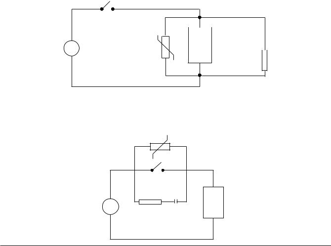
Inductive Coils - MOV's are recommended for transient suppression in inductive coils connected in parallel and as close as possible to the coil. See Figure 2-2 (below). Additional protection may be provided by adding an RC network across the MOV.
Contacts - Arcing may occur across contacts when the contact opens and closes. This results in electrical noise as well as damage to the contacts. Connecting a RC network properly sized can eliminate this arc.
For circuits up to 3 amps, a combination of a 47 ohm resistor and a 0.1 microfarad capacitor (1000 volts) is recommended. For circuits from 3 to 5 amps, connect 2 of these in parallel. See Figure 2-3 (below).
FIGURE 2-2
|
|
|
|
|
|
|
C |
0.5 |
|
|
|
|
|
|
|
mfd |
|
|
|
|
|
|
|
|
||
|
|
|
|
|
|
|
||
|
|
|
Inductive |
1000V |
||||
A.C. |
MOV |
|
|
|||||
|
Load |
|
|
|
|
|||
|
|
|
|
|
|
|||
R 220 ohms
115V 1/4W
230V 1W
FIGURE 2-3
MOV
A.C. |
|
|
Inductive |
R |
C |
Load |
Edition 3 |
2-4 |
Section 2 |
Rev G

Sensor Placement (Thermocouple or RTD)
Thermocouple lead resistance should not exceed 300 ohms. If this is exceeded, instrument accuracy could be affected.
Two wire RTD's should be used only with lead lengths less than 10 feet.
If the temperature probe is to be subjected to corrosive or abrasive conditions, it should be protected by the appropriate thermowell. The probe should be positioned to reflect true process temperature:
In liquid media - the most agitated area
In air - the best circulated area
Section 2 |
2-5 |
Edition 3 |
Rev G

2.3 WIRING CONNECTIONS - INPUTS
All wiring connections are typically made to the instrument at the time of installation. Connections should be made at the terminal blocks, one 14 gauge wire maximum, using copper conductors except for thermocouple inputs. See Figure 2-4 (below) for the terminal block locations. The recommended torque for the AC Mains connector on the power supply board is 113oz-ins and the recommended torque for all other connectors in the unit is 85oz-ins.
FIGURE 2-4
TRANSMITTER POWER SUPPLY BOARD COMMUNICATIONS BOARD
|
|
|
|
|
|
|
|
|
|
|
|
|
|
|
|
|
|
|
|
|
|
|
|
|
|
|
|
|
|
|
|
|
|
|
|
|
|
|
|
|
|
|
|
|
|
|
|
|
|
|
|
|
|
|
|
|
|
|
|
|
|
|
|
|
|
|
|
|
|
|
|
|
|
|
|
|
|
|
|
|
|
|
|
|
|
|
|
|
|
|
|
|
|
|
|
|
|
|
|
|
|
|
|
|
|
|
|
|
|
|
|
|
|
|
|
|
|
|
|
|
|
|
|
|
|
|
|
|
|
|
|
|
|
|
|
|
|
|
|
|
|
|
|
|
|
|
|
|
|
|
|
|
|
|
|
|
|
|
|
|
|
|
|
|
|
|
|
|
|
|
|
|
|
|
|
|
|
|
|
|
|
|
|
|
|
|
|
|
|
|
|
|
|
|
|
|
|
|
|
|
|
|
|
|
|
|
|
|
|
|
|
|
|
|
|
|
|
|
|
|
|
|
|
|
|
|
|
|
|
|
|
|
|
|
|
|
|
|
|
|
|
|
J1 |
|
|
|
|
|
|
|
|
|
|
|
|
|
|
J3 |
|
|
|
|||||||||||
|
|
|
|
|
|
|
|
|
|
|
|
|
|
|
|
|
|
|
|
|
|
|
|
|
|
|
|
|
|
|
||||||||
|
|
|
|
|
|
|
|
|
|
|
|
J4 |
|
|
|
|
|
|
|
|
|
|
|
|
|
|
|
|
|
|
|
|
|
|
||||
|
|
|
|
|
|
|
|
|
|
|
|
|
|
|
|
|
|
|
|
|
|
|
|
|
|
|
|
|
|
|
|
|
|
|||||
|
|
|
|
|
|
|
|
|
|
|
|
|
|
MOTHER BOARD |
|
|
|
|
J5 |
|
|
|
||||||||||||||||
|
|
|
|
|
|
|
|
|
|
|
|
|
|
|
|
|
|
|
|
|
||||||||||||||||||
|
|
|
|
|
|
|
|
|
|
|
|
|
|
|
|
|
|
|
|
|
|
|
|
J6 |
|
|
|
|
|
|
|
|||||||
|
|
|
|
|
|
|
|
|
|
|
|
|
|
|
|
|
|
|
|
|
|
|
|
|
|
|
|
|
|
|
||||||||
|
|
|
|
|
|
|
|
|
|
|
|
|
|
|
|
|
|
|
|
|
|
|
|
|
|
|
|
|
|
|
||||||||
|
|
|
POWER |
|
|
|
|
|
|
|
|
|
|
|
|
|
|
|
|
|
|
|
|
|
|
|
|
|
|
|
||||||||
|
|
|
|
|
|
|
|
|
|
|
Conn J7 |
|
|
|
|
|
|
|
|
|
|
|
||||||||||||||||
|
|
|
|
|
|
|
|
|
|
|
|
|
|
|
|
|
|
|
|
|
|
|
|
|
|
|
|
|
|
|
|
|
||||||
|
|
|
|
|
|
|
|
|
|
|
|
|
|
|
|
|
|
|
|
|
|
|
|
|
|
|
|
|
|
|
|
|
||||||
|
|
|
SUPPLY |
|
|
|
|
|
|
|
|
|
|
|
|
|
|
|
|
|
|
|
|
|
|
|
|
|
|
|
|
|
|
|
|
|
|
|
|
|
|
BOARD |
|
|
|
|
|
|
|
|
|
|
|
|
|
|
|
|
|
|
|
|
|
|
|
|
|
|
|
|
|
|
|
|
|
|
|
|
|
|
|
|
|
|
|
|
|
|
|
|
|
|
|
|
4 HIGH |
|
|
|
|
|
|
|
|
|||||||||||||
|
|
|
|
|
|
|
|
|
|
|
|
|
|
|
|
|
|
|
|
|
|
|
|
|
|
|
|
|
|
|
|
|||||||
|
|
|
|
|
|
|
|
|
|
|
|
|
|
|
|
|
|
|
|
|
|
|
|
|
|
|
|
2 HIGH |
|
|
|
|||||||
|
|
|
|
|
|
|
|
|
|
|
|
2 HIGH |
|
|
|
|
|
|
|
|
|
|
|
|
|
|
||||||||||||
|
|
|
|
|
|
|
|
|
|
|
|
RELAY |
|
|
|
|
|
|
|
INPUT |
|
|
|
4-20 |
|
|
|
|||||||||||
|
|
|
|
|
|
|
|
|
|
|
|
BOARD |
|
|
|
|
|
|
BOARD |
|
|
|
|
OUTPUT |
|
|
|
|||||||||||
|
|
|
AC |
|
|
|
|
|
|
|
|
|
|
|
|
|
|
|
|
|
|
|
|
|
|
|
|
|
|
|
|
|
|
BOARD |
|
|
|
|
|
|
|
|
|
|
|
|
|
|
|
|
|
|
|
|
|
|
|
|
|
|
|
|
|
|
|
|
|
|
|
|
|
|
|
|
|||
|
|
|
|
|
|
|
|
|
|
|
|
|
|
|
|
|
|
|
|
|
|
|
|
|
|
|
|
|
|
|
|
|
|
|
|
|
||
|
|
|
MAINS |
|
|
|
|
|
|
|
|
TB1 |
|
|
|
|
TB1 TB2 |
|
|
|
|
|
|
|
|
|||||||||||||
|
|
|
|
|
|
|
|
|
|
|
|
|
|
|
|
|
|
|
|
|
|
|
|
|
|
|
|
|
|
|
|
|
|
|
|
|
|
|
|
|
|
|
|
|
|
|
|
|
|
|
|
|
|
|
|
|
|
|
|
|
|
|
|
|
|
|
|
|
|
|
|
|
|
|
|
|
|
|
|
|
|
|
|
|
|
|
|
|
|
|
|
|
|
|
|
|
|
|
|
|
|
|
|
|
|
|
|
|
|
|
|
|
|
|
|
|
The instrument case may have numerous conduit openings, EC1 - EC6, depending upon the number of inputs and outputs specified (EC5 and EC6 are not included on all models). To help minimize electrical noise that may adversely affect the operation of the instrument, do not run input and/or 4-20mA output connections through the same conduit entry as relay or power supply connections. See Figure 2-1B (page 2-2) for conduit opening locations.
Edition 3 |
2-6 |
Section 2 |
Rev G

2.3.1 SHIPPED CONFIGURATION/JUMPER POSITIONING
Each instrument is factory shipped with all parameters set to default values. These defaults are shown in the "display" box for each parameter in Section 4.
Jumpers are used to condition the sensor inputs. All jumpers are located on the Input Board(s). The instrument is shipped from the factory with these jumpers configured as follows:
JU1 |
IF FITTED |
UPSCALE BREAK |
JU2 |
|
Non-Contact Closure Input |
JU3 |
|
T/C, mV, 0/1V, Switch, mA |
JU4 |
IF FITTED |
UPSCALE BREAK |
JU5 |
|
Non-Contact Closure Input |
JU6 |
|
T/C, mV, 0/1V, Switch, mA |
JU7 |
|
WIDE SPAN |
JU8 |
|
WIDE SPAN |
JU11 |
IF FITTED |
Non-RTD |
JU12 |
IF FITTED |
Non-RTD |
JU15 |
|
Non-mA |
JU16 |
|
Non-mA |
There are 2 additional jumpers per Input Board that are used for ID. These must be positioned as shown in Table 2-1 below as per their location inside the instrument. Board 1 is the bottom board.
TABLE 2-1 BOARD ID JUMPERS
|
Inputs |
Inputs |
|
1, 3, 5, 7 |
2, 4, 6, 8 |
Board Position |
JU13 |
JU14 |
Board 1 |
|
|
Board 2
Board 3
Board 4
If any board is removed from the instrument in a multiple stack of boards, it MUST BE installed in the correct sequence or these jumpers MUST BE moved. If not installed correctly, calibration will be affected.
2.3.2 SENSOR BREAK and OUT-OF-RANGE DETECTION
Sensor break and out-of-range conditions are determined and handled by the software. When either occurs, the software will drive the input value to +99999 or -99999 based upon whether SENSOR BREAK is software configured for UPSCALE or DOWN SCALE in Input Configuration. Any outputs will react accordingly. Out-of-range is defined as being more than 5% out of the span established by RANGE LIMIT LOW and RANGE LIMIT HIGH.
For 5 or 10 Volt and Current inputs, the analog signal goes to zero when there is a sensor break, due to voltage divider or shunt resistors. For sensor break detection to work on these input types, the INPUT RANGE LOW (analog signal low) and/or RANGE LIMIT LOW (engineering units low) parameters must be set high enough such that at zero volts/mA, the resultant value will be at least 5% below the span established by RANGE LIMIT LOW and RANGE LIMIT HIGH.
Section 2 |
2-7 |
Edition 3 |
Rev G
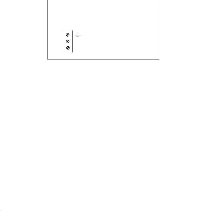
2.3.3 AC POWER CONNECTIONS
WARNING: UNIT SHOULD HAVE A POWER SWITCH OR CIRCUIT BREAKER IN CLOSE PROXIMITY OF EQUIPMENT AND WITHIN EASY REACH OF THE OPERATOR. THE SWITCH SHALL BE MARKED AS THE DISCONNECTING DEVICE FOR THE UNIT.
FIGURE 2-6
Connect the line voltage, hot and neutral, to L and N respectively. Connect the ground wire to the terminal labeled G.
UNIVERSAL POWER SUPPLY
G
N
L
~
~
Edition 3 |
2-8 |
Section 2 |
Rev G
 Loading...