


Power Window Control System
Installation and Programming Guide
Power Window Control System
Installation and Prog
ramming Guide

Table of Contents
Power Window Control System Window Preparation
Existing Window or New Window ............................3-XX
Power Window Control System Installation
New Construction. ...................................5-11
Existing Construction . ................................12-19
Power Window Control System Programming
Console Programming ................................21-22
Remote Control Programming.............................23-24
Power Window Control System Operation...........................25
Power Window Control System Wiring Diagram ........................26
Power Window Control System Operation Codes .......................27
Trouble Shooting .....................................28-30
Regulatory Compliance....................................31
Warranty .........................................32-33
000XXXX
2

Power Window Control System Window Preparation
Power Window Control System Window Preparation
XX
000XXXX
3

Power Window Control System Installation Guide
Power Window Control System Installation Guide
for Andersen® Awning Windows with Power Windows
for Andersen® Awning Windows with Power Windows
Thank you for choosing Andersen. / Gracias por elegir Andersen.
Thank you for choosing Andersen. / Gracias por elegir Andersen.
For questions call 1-888-888-7020. For more information and/or guides visit andersenwindows.com.
Please leave this guide with building owner.
Si tiene alguna pregunta llame al 1-888-888-7020. Para obtener más información y/o guías, visite andersenwindo
Deje esta guía con el dueño de la construcción.
This document is under construction
do not print, publish, or distribute
ws.com.
▶ Read guide from beginning to end before star
Lea completamente la guía antes de comenzar la instalación. Lea y respete todas las advertencias y precauciones durante la instalación de la unidad.
▶ Check with your local building code ofcial to identify and conrm compliance with local building code requirements.
Consulte los códigos locales de construcción para identicar y conrmar que se cumplan los requisitos del código de construcción.
Parts Included / Parts Included
(1) Power Box Components / Power Box Components
(1) Key Pad / Key Pad
(1) Mounting Ring / Mounting Ring
(7) 1/2" Screws / 1/2" Screws
(1) Installation Instructions / Installation Instructions
Tools Needed / Tools Needed
∙ Safety glasses / Safety glasses
∙ T
ape measure / Tape measure
∙ Drill/Driv
∙ W
∙ W
∙ Phillips Head Scre
∙ 1/2" Spade Bit / 1/2" Spade Bit
∙ T
∙ Hammer / Hammer
∙ P
∙ 3/8" Drill Bit / 3/8” Drill Bit
Supplies Needed / Supplies Needed
∙ 18-3 Conductor Wire / 18-3 Strand Conductor Wire
∙ 14-2(min)
∙ 1-5/8" Dr
∙ Outlet Box Cable Clamps / Outlet Box Cable Clamps
∙ W
∙ Dr
er / Drill/Driver
ire Cutter / Wire Cutter
ire Stripper / Wire Stripper
w Driver / Phillips Head Screw Driver
ape Measure / Tape Measure
aper Clip / Paper Clip
High Voltage Wire / 14-2(min) High Voltage Wire
ywall Screws / 1-5/8” Drywall Screws
ire Staples / Wire Staples
ywall Saw / Drywall Saw
ting installation. Read all warnings and cautions during unit installation.
Power Box
Power Box
Mounting Ring
Mounting Ring
Key Pad
Key Pad
▶ For installation in new construction, see page 5.
▶ For installation in new construction, see page 5.
▶ F
or installation in existing construction, see page 12.
▶ For installation in existing construction, see page 12.
Use caution when working at elevated heights and around unit openings.
Follow manufacturers’ instructions for ladders and/or scaffolding. Failure
to do so may result in injury or death.
Sea cauteloso al trabajar en lugares elevados y cerca de las aberturas de
la unidad. Siga las instr
y/o andamios. Si no lo hiciera, podrían producirse lesiones o la muerte.
“Andersen” and all other marks where denoted are trademarks of Andersen Corporation. ©2012-2012 Andersen Corporation. All rights reserved.
“Andersen” y las demás marcas que aparezcan son marcas registradas de Andersen Corporation. ©2012-2012 Andersen Corporation. Todos los derechos reser
ucciones del fabricante para el uso de escaleras
Follow manufacturers’ instructions for hand or power tools. Always
wear saf
product damage.
Siga las instrucciones del fabricante para el uso de herramientas
eléctricas o manuales. Utilice siempre gafas de seguridad. Si no lo
hiciera,
ety glasses. Failure to do so may result in injury and/or
podrían producirse lesiones y/o daños al producto.
vados.
Electric Operator
Electric Operator
XXXXXXX BA Revised 01/11/13
Power Window Control System Installation (New Construction)
Power Window Control System Installation (New Construction)
▶ See wiring diagram for proper wire conguration prior to starting
▶ See wiring diagram for proper wire conguration prior to star
XX
ting
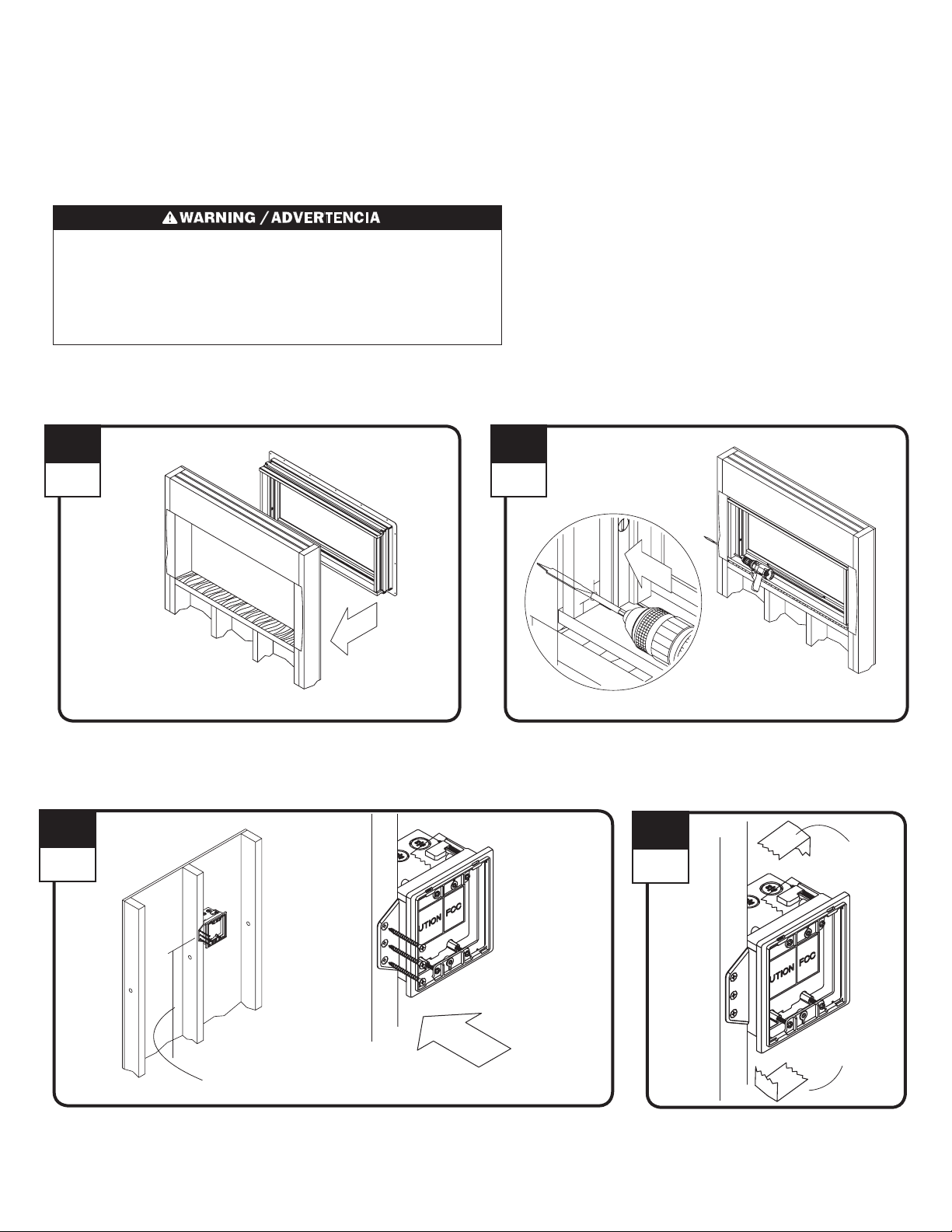
1
Interior
Install window following installation instructions.
Install window following installation instructions.
3
Interior
2
Interior
Drill 3/8" hole through side extension jamb as shown.
Drill 3/8” hole through side extension jamb as shown.
4
Interior
Tape
Tape
54" (48" top of box - ADA locations)
54" (48" top of box - ADA locations)
Locate power box on interior wall, 54" above oor (48" top of box - ADA locations) and within
50 feet of windo
Locate power box on interior wall, 54” above oor (48” top of box - ADA locations) and within
50 feet of windo
000XXXX
w. Attach box to stud using three drywall screws.
w. Attach box to stud using three drywall screws.
5
Tape
Tape
Remove tape.
Remove tape.
5
Interior
14-2 (min.) Wire
14-2 (min.) Wire
Run 18-3 wire through side jamb between power box and awning window(s) and run 14-2 (min.)
wire to power box location.
Run 18-3 wire through side jamb between power box and awning window(s) and run 14-2 (min.)
wire to po
wer box location.
18-3 Wire
18-3 Wire
Side Jamb
Side Jamb
Run 18-3 wire to
midpoint of window.
Run 18-3 wire to
midpoint of window.
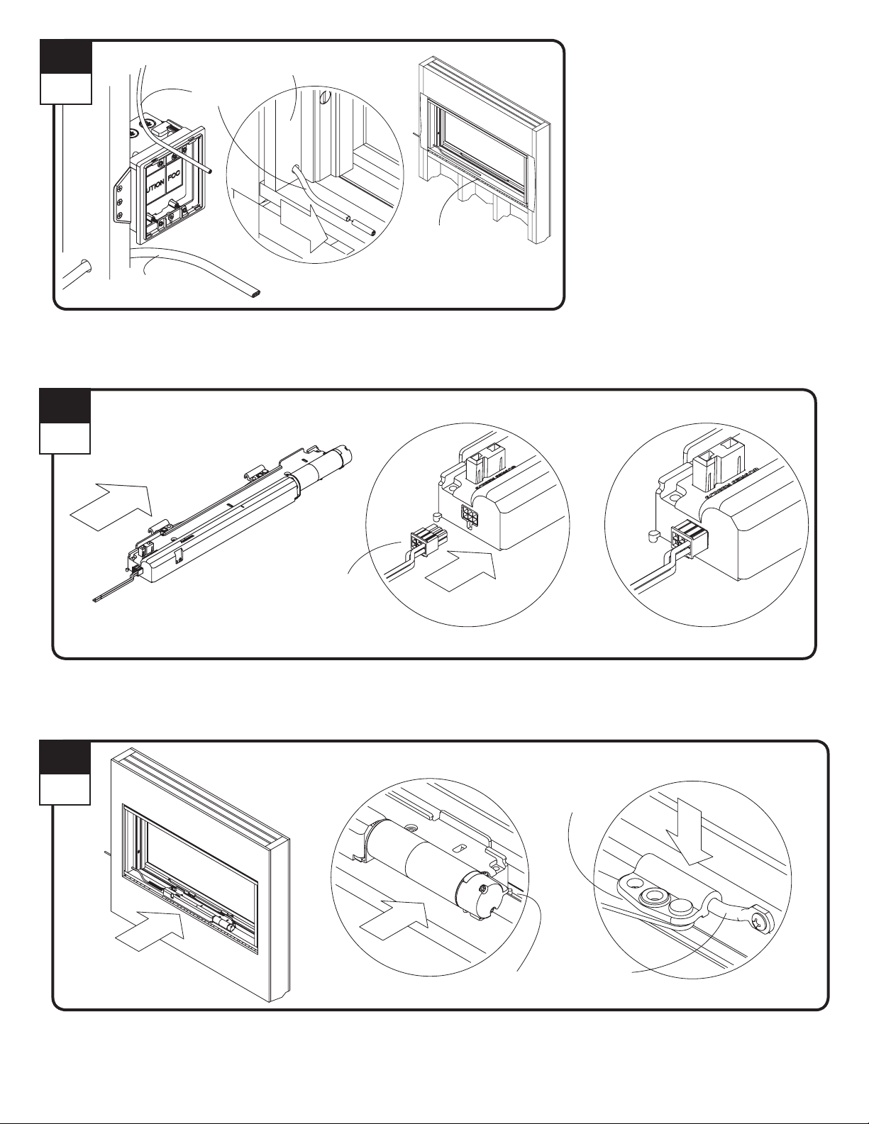
6
Interior
Plug pigtail wire into electric operator.
Plug pigtail wire into electric operator.
7
Interior
Pigtail Wire
Pigtail Wire
Kerf
Kerf
Operator Arm
Operator Arm
Sash Bar
Sash Bar
Position electric operator over predrilled holes on sill with operator tabs in locating kerf. Attach electric operator arms to sash bar.
Position electric operator over predrilled holes on sill with operator tabs in locating kerf. Attach electric operator arms to sash bar.
000XXXX
6

8
Interior
Fasten electric operator with four (4) screws.
Fasten electric operator with four (4) screws.
9
Interior
Do not over drive screws. Product
damage may result.
No ajuste demasiado los tornillos.
El producto se puede dañar
.
Strip pigtail wire ends and align same color wires with 18-3 wires and connect with wire nuts. Make sure wire color continuity is maintained.
Strip pigtail wire ends and align same color wires with 18-3 wires and connect with wire nuts. Make sure wire color continuity is maintained.
10
Interior
Face Plate
Face Plate
Remove face plate.
Remove face plate.
11
Interior
Remove wiring access hole grommets.
Remove wiring access hole grommets.
12v DC Grommet
12v DC Grommet
120v AC Grommet
120v AC Grommet
000XXXX
7

12
Interior
Foam Packing Block
Foam Packing Block
13
Interior
Route 18-3 wire through larger compartment
Route 18-3 wire through larger compartment
6"
Turn power off to this
circuit. Failure to do so may
result in personal injury.
Turn power off to this
Route 14-2(min) wire
through smaller compartment.
Route 14-2(min) wire
through smaller compar
tment.
circuit. F
result in personal injury.
ailure to do so may
Remove foam packing block.
Remove foam packing block.
14
Interior
Strip wire ends.
Strip wire ends.
18-3 Wire
18-3 Wire
14-2 (min.) Wire
14-2 (min.) Wire
Run 14-2(min) wire into smaller compartment of power box and 18-3
wire into larger compartment of power box. See wiring diagram xxxxx
Run 14-2(min) wire into smaller compartment of power box and 18-3
wire into larger compartment of power box. See wiring diagram at step 6.
15
Interior
14-2 (min.) Wire
14-2 (min.) Wire
Align 14-2(min.) wires to black and white wires in smaller
compartment of power box and connect with wire nuts.
Align 14-2(min.) wires to black and white wires in smaller
compar
tment of power box and connect with wire nuts.
16
Interior
Tuck connected 14-2(min.) wires into small compartment of power
box, as shown.
Tuck connected 14-2(min.) wires into small compartment of power
box,
as shown.
000XXXX
17
Interior
Align color 18-3 wires to same colored wires in larger compartment
and connect with wire nuts.
Align color 18-3 wires to same colored wires in larger compartment
and connect with wire nuts.
8
18-3 Wire
18-3 Wire

18
Interior
Battery
Battery
Remove tape from battery terminals. Align and connect red and black leads to red and black battery terminals.
Remove tape from battery terminals. Align and connect red and black leads to red and black battery terminals.
Tape
Tape
Red
Red
Terminals
Terminals
Black
Black
19
Interior
Tuck connected 18-3 wires into large compartment of power box and reapply faceplate, as shown.
Tuck connected 18-3 wires into large compartment of power box and reapply faceplate, as shown.
21
Interior
22
Interior
20
Interior
Remove mounting ring and screws from
power box.
Remove mounting ring and screws from
power box.
Mounting Ring
Mounting Ring
Install drywall.
Install drywall.
000XXXX
Drywall
Drywall
Reapply mounting ring and fasten with screws.
Reapply mounting ring and fasten with screws.
9

23
Interior
Fasten remodeling clip.
Fasten remodeling clip.
24
Interior
Fasten wire harness from power box to keypad connector pins.
Fasten wire harness from power box to keypad connector pins.
Keypad
Keypad
25
Interior
Wire Harness
Wire Harness
Keypad Connector pins
Keypad Connector pins
26
Interior
Position keypad to mounting ring.
Position keypad to mounting ring.
000XXXX
Open keypad panel and fasten.
Open keypad panel and fasten.
10

27
Interior
Electric Operator Cover
Electric Operator Cover
Apply nish to electric operator cover and snap LED cover lens to cover as shown.
Apply nish to electric operator cover and snap LED cover lens to cover as shown.
LED Cover Lens
LED Cover Lens
28
Interior
29
Interior
Insect Screen
Insect Screen
Install insect screen. Insect screen must be in
place for electric operator motor to operate.
Install insect screen. Insect screen must be in
place for electric operator motor to operate.
Insect Screen Sensor
Insect Screen Sensor
Rotate slightly and snap sill cover onto motor housing. Screen sensor must pop up through hole
in cover.
Rotate slightly and snap sill cover onto motor housing. Screen sensor must pop up through hole
in cover.
000XXXX
11
▶ Power window control system installation
for new construction is complete.
Power window control system installation
for ne
w construction is complete.

Power Window Control System Installation (Existing Construction)
Power Window Control System Installation (Existing Constr
▶ See wiring diagram for proper wire conguration prior to starting
▶ See wiring diagram for proper wire conguration prior to star
XX
1
Interior
2
Interior
ting
uction)
Remove tape.
Remove tape.
3
Interior
Remove attachment tab.
Remove attachment tab.
Remove mounting ring and screws from power box.
Remove mounting ring and screws from power box.
4
Interior
Locate power box at eye-level within 50 feet of window. Trace face of
power box on wall.
Locate power box at eye-level within 50 feet of window. Trace face of
po
wer box on wall.
000XXXX
12

5
6
Interior
Attach screw and cut drywall on traced line.
Attach screw and cut drywall.
7
Interior
1-5/8"
Drywall Screw
1-5/8"
Dr
ywall Screw
Drywall Saw
Drywall Saw
Interior
Remove cut drywall.
Remove cut drywall.
Drill 3/8” hole through side extension jamb as shown.
Drill 3/8” hole through side extension jamb as shown.
8
18-3 Wire
Interior
14-2 (min.) Wire
14-2 (min.) Wire
Run 18-3 wire through side jamb between power box and awning window(s) and run 14-2 (min.) wire to power box location.
Run 18-3 wire through side jamb between power box and awning window(s) and run 14-2 (min.) wire to power box location.
18-3 Wire
Side Jamb
Side Jamb
Run 18-3 wire to
midpoint of window.
Run 18-3 wire to
midpoint of windo
w.
000XXXX
13

9
Interior
Plug pigtail wire into electric operator.
Plug pigtail wire into electric operator.
10
Interior
Pigtail Wire
Pigtail Wire
Position electric operator. Attach electric operator arms to sash bar.
Position electric operator. Attach electric operator arms to sash bar.
11
Interior
Measure and mark center of sill.
Measure and mark center of sill.
000XXXX
14

12
Interior
Position center of electric operator at marked line on sill with operator tabs in locating kerf.
Position center of electric operator at marked line on sill with operator tabs in locating kerf.
Center of Electric Operator
Center of Electric Operator
Pencil Mark
Pencil Mark
Kerf
Kerf
13
Interior
Fasten electric operator with four (4) screws.
Fasten electric operator with four (4) screws.
14
Interior
Do not over drive screws. Product
damage may result.
No ajuste demasiado los tornillos.
El producto se puede dañar.
Strip pigtail wire ends and align same color wires with 18-3 wires and connect with wire nuts. Make sure wire color continuity is maintained.
Strip pigtail wire ends and align same color wires with 18-3 wires and connect with wire nuts. Make sure wire color continuity is maintained.
000XXXX
15

15
20a
Interior
12v DC Grommet
12v DC Grommet
120v AC Grommet
120v AC Grommet
16
Interior
Face Plate
Face Plate
17
Interior
Foam Packing Block
Foam Packing Block
Remove wiring access hole grommets.
Remove wiring access hole grommets.
18
Interior
Reapply mounting ring and fasten with
screws.
Reapply mounting ring and fasten with
scre
ws.
Remove faceplate.
Remove faceplate.
19
Interior
Run 14-2(min) wire into smaller compartment of power box and 18-3 wire into larger
compartment of power box. See wiring diagram xxxxx
Run 14-2(min) wire into smaller compartment of power box and 18-3 wire into larger
compar
tment of power box. See wiring diagram at step 6.
Remove foam packing block.
Remove foam packing block.
Turn power off to this circuit. Failure to
do so may result in personal injury.
Turn power off to this circuit. Failure to
do so may result in per
Route 18-3 wire through
larger compartment
Route 18-3 wire through
larg
er compartment
Route 14-2(min) wire through
smaller compartment.
Route 14-2(min) wire through
smaller compar
sonal injury.
tment.
20
Interior
Position power box into cut out area in wall.
000XXXX
21
Interior
Fasten remodeling clip.
Fasten remodeling clip.
16

22
23
24
Interior
Strip wire ends.
Strip wire ends.
25
Interior
18-3 Wire
18-3 Wire
14-2 (min.) Wire
14-2 (min.) Wire
18-3 Wire
18-3 Wire
Interior
14-2 (min.) Wire
14-2 (min.) Wire
Align 14-2(min.) wires to black and white wires
in smaller compartment of power box and
connect with wire nuts.
Align 14-2(min.) wires to black and white wires
in smaller compar
connect with wire nuts.
tment of power box and
26
Interior
Interior
Tuck connected 14-2(min.) wires into small
compartment of power box, as shown.
Tuck connected 14-2(min.) wires into small
compar
tment of power box, as shown.
Tape
Tape
Red
Red
Align color 18-3 wires to same colored wires in
larg
er compartment and connect with wire nuts.
Align color 18-3 wires to same colored wires in
larger compartment and connect with wire nuts.
27
Interior
Terminals
Terminals
Battery
Battery
Remove tape from battery terminals. Align and connect red and black leads to red and black
battery terminals.
Remove tape from battery terminals. Align and connect red and black leads to red and black
battery terminals.
Black
Black
Tuck connected 18-3 wires into large compartment of power box and reapply faceplate, as shown.
Tuck connected 18-3 wires into large compartment of power box and reapply faceplate, as shown.
000XXXX
17

28
Interior
Fasten wire harness from power box to keypad connector pins.
Fasten wire harness from power box to keypad connector pins.
Keypad
Keypad
29
Interior
Wire Harness
Wire Harness
Keypad Connector pins
Keypad Connector pins
30
Interior
Position keypad to mounting ring.
Position keypad to mounting ring.
31
Interior
Electric Operator Cover
Electric Operator Cover
Apply nish to electric operator cover and snap LED cover lens to cover as shown.
Apply nish to electric operator cover and snap LED cover lens to cover as shown.
Open keypad panel and fasten.
Open keypad panel and fasten.
LED Cover Lens
LED Cover Lens
000XXXX
18

32
3
33
Interior
Interior
Insect Screen
Insect Screen
Install insect screen. Insect screen must be in
place for electric operator motor to operate.
Install insect screen. Insect screen must be in
place for electric operator motor to operate.
▶ P
ower window control system installation
in existing construction is complete.
▶ P
ower window control system installation
in existing construction is complete.
Insect Screen Sensor
Insect Screen Sensor
Rotate slightly and snap sill cover onto motor housing. Screen sensor must pop up through hole
in cover.
Rotate slightly and snap sill cover onto motor housing. Screen sensor must pop up through hole
in co
ver.
000XXXX
19

Power Window Control System
Console and Remote Control Operation and Programing
Power Window Control System
Console and Remote Control Oper
ation and Programing
for Andersen® Awning Windows with Power Windows
for Andersen® Awning Windows with Power Windows
Thank you for choosing Andersen. / Gracias por elegir Andersen.
Thank you for choosing Andersen. / Gracias por elegir Andersen.
For questions call 1-888-888-7020. For more information and/or guides visit andersenwindows.com.
Please leave this guide with building owner.
Si tiene alguna pregunta llame al 1-888-888-7020. Para obtener más información y/o guías, visite andersenwindo
Deje esta guía con el dueño de la construcción.
▶ Read guide from beginning to end before star
Lea completamente la guía antes de comenzar la instalación. Lea y respete todas las advertencias y precauciones durante la instalación de la unidad.
▶ Check with your local building code ofcial to identify and conrm compliance with local building code requirements.
Consulte los códigos locales de construcción para identicar y conrmar que se cumplan los requisitos del código de construcción.
This document is under construction
do not print, publish, or distribute
ws.com.
ting installation. Read all warnings and cautions during unit installation.
Console
Console
▶ For console programming, see page 21.
▶ For console programming, see page 21.
▶ F
or remote control programming, see page 23.
▶ For remote control programming, see page 23.
Use caution when working at elevated heights and around unit openings.
Follow manufacturers’ instructions for ladders and/or scaffolding. Failure
to do so may result in injury or death.
Sea cauteloso al trabajar en lugares elevados y cerca de las aberturas de
la unidad. Siga las instr
y/o andamios. Si no lo hiciera, podrían producirse lesiones o la muerte.
“Andersen” and all other marks where denoted are trademarks of Andersen Corporation. ©2013-2013 Andersen Corporation. All rights reserved.
“Andersen” y las demás marcas que aparezcan son marcas registradas de Andersen Corporation. ©2013-2013 Andersen Corporation. Todos los derechos reser
ucciones del fabricante para el uso de escaleras
Follow manufacturers’ instructions for hand or power tools. Always
wear saf
product damage.
Siga las instrucciones del fabricante para el uso de herramientas
eléctricas o manuales. Utilice siempre gafas de seguridad. Si no lo
hiciera,
ety glasses. Failure to do so may result in injury and/or
podrían producirse lesiones y/o daños al producto.
vados.
Remote Control
Remote Control

Power Window Control System Programming Procedure (Console)
Power Window Control System Programming Procedure (Console)
▶ XXX
▶ XXX
XX
1
Interior
If insect screen is not present, screen sensor must be depressed for electric operator motor to operate.
If insect screen is not present, screen sensor must be depressed for electric operator motor to operate.
Insect Screen Sensor
Insect Screen Sensor
With Operator Cover in Place/ With Operator Cover in Place
Insect Screen Sensor
Insect Screen Sensor
Without Operator Cover in Place/ Without Operator Cover in Place
Press and hold a paper clip into the window prorgram button on the electric operator cover until red LED starts blinking.
Press and hold a paper clip into the window prorgram button on the electric operator cover until red LED starts blinking.
000XXXX
21

000
2
h
a
y
elector Switc
Selector Switch
Move selector switch on key pad to “ON” position
Move selector switch on key pad to “ON” position.
3
ispla
Display
3X
Program Button
Program Button
Insert paper clip into console’s program button location and hold until key pad LED blinks 3 times slowly and “E” is displayed on the screen
Insert paper clip into console’s program button location and hold until key pad LED blinks 3 times slowly and “E” is displayed on the screen.
4
elect console keypad button (1, 2, 3, or 4) and press “Open” on the numbered button for the window you want to operateThe selected numbered
utton will blink 3 times quickly, and the red window operator LED will stop blinking when the operator is programmed If red LED on the operator
sill cover remains blinking, repeat steps 2-5 until operator is programmed
Select console keypad button (1, 2, 3, or 4) and press “Open” on the numbered button for the window you want to operate. The selected numbered
button will blink 3 times quickly, and the red window operator LED will stop blinking when the operator is programmed. If red LED on the operator
sill cover remains blinking, repeat steps 2-5 until operator is programmed.
ower window console programming is complete.
Power window console programming is complete.
XXXX
Repeat steps 3-4 to program up to four windows.
2

3
n
CD
Power Window Control System Programming Procedure (Remote Control)
Power Window Control System Programming Procedure (Remote Control)
XXX
▶ XXX
1
Move selector switch on console to the “OFF” positio
Move selector switch on console to the “OFF” position.
2
3X
nsert paper clip into program button location and hold until key pad LED blinks 3 times slowly and “H” is displayed on the L
Insert paper clip into program button location and hold until key pad LED blinks 3 times slowly and “H” is displayed on the LCD.
XXXX
2

3 4
3X
Move selector switch on remote control to the “ON” position.
Move selector switch on remote control to the “ON” position.
Insert paper clip into enrollment button location and hold until key pad
LEDs blink 3 times slowly.
Insert paper clip into enrollment button location and hold until key pad
LEDs blink 3 times slo
wly.
5
3X
3X
After short delay, both remote and console LEDs will blink 3 times quickly, and the remote will be programed to the console. If LEDs do not blink
3 times quickly on both units, wait for console to time out and repeat steps 2-5 until remote is programed.
After short delay, both remote and console LEDs will blink 3 times quickly, and the remote will be programed to the console. If LEDs do not blink
3 times quickly on both units,
wait for console to time out and repeat steps 2-5 until remote is programed.
6
Move selector switch on the console to the “ON” position to return to normal operating mode.
Move selector switch on the console to the “ON” position to return to normal operating mode.
000XXXX
24
▶ P
ower window remote control programming is complete.
Power window remote control programming is complete.
▶ Repeat steps 4-6 to program up to four windows.
Repeat steps 4-6 to program up to four windows.

Power Window Control System Operation
Power Window Control System Operation
1
Push ( U ) on numbered button on key pad to open window. Display will light and window will open until stop button is pushed or window is fully opened. Push and release ( V ) to close window.
Push ( U ) on numbered button on key pad to open window. Display will light and window will open until stop button is pushed or window is fully opened. Push and release ( V ) to close window.
000XXXX
25

Power Window Control System Wiring Diagram
Power Window Control System Wiring Diagram
Daisy Chain Connection
Operator 4
Operator 3
Operator 2
Star Connection
Operator 1
Operator 4
Operator 3
Operator 2
Operator 1
Single Connection
000XXXX
26

Power Window Control System Operation Codes
Power Window Control System Operation Codes
Use these codes to help trouble shoot power window problems. Refer to the instruction guide for detailed
installation and operation guidelines. Call Andersen at 1-888-888-7020 for further assistance.
Use these codes to help trouble shoot power window problems. Refer to the instruction guide for detailed
installation and operation guidelines.
Call Andersen at 1-888-888-7020 for further assistance.
LOW BATT lights up to designate
battery may need to be charged or
replaced. Power window is using
AC power source only.
OPEN lights up to designate
window is open or in the operation
of opening. (Units 1-4)
CLOSED lights up to designate
window is closed or in the
operation of closing. (Units 1-4)
NO SCREEN lights up to designate
that no insect screen is present.
Power window will not operate until
screen sensor is fully depressed.
(Units 1-4)
OBSTRUCTION lights up to
designate power window has
detected an obstruction and will
not fully open or close. (Units 1-4)
000XXXX
RAIN lights up to designate
window will close due to rain or
condensation.
RAIN OVERRIDE lights up to
designate override has been
activated. Rain override stays
on and window will remain open
until timer expires. If rain or
condensation is not present after
one hour, the window will remain
open; if moisture is present the
window will close.
27

Power Window Control System Trouble Shooting
Power Window Control System Trouble Shooting
Issue/ Issue Things To Check / Things To Check
Power driver Does
Not Operate - Open
or Close
Power driver Does
Not Oper
ate - Open
or Close
1) Make sure the screen is properly installed
and red screen sensor is depressed.
2) Make sure the control panel is set to the ON
position.
3) Check to make sure driver arms are
attached to sash.
4) Make sure the control panel, driver and
remote are all adequately powered:
- Control panel switch is set to ON position
- All wires are plugged in.
- Check wiring diagram and conrm wire
connections.
5) Check window and driver for obstruction:
- Weatherstripping
- Debris
- Sash misalignment
- Power operator misalignment
6) Conrm driver is correctly programmed to
the control panel and/or remote.
7) Check for moisture on the rain sensors.
Initiate rain senor override if needed.
8) Make sure driver is installed on a window
within the correct weight limit.
Power Operator Has
Intermittent Opening/
Closing
Power Operator Has
Inter
mittent Opening/
Closing
9) Make sure window is unlocked.
10) Check Low Battery indicator, replace
battery if necessary.
11) Check 10 Amp fuse on red wire to battery
conection. Located in control panel box.
See: Power Operator Does Not Operate Or
Close Section
1) Check for short/break in wiring. Make sure
everything is properly grounded.
2) Make sure screen is properly installed and
screen sensor is depressed
000XXXX
28

Trouble Shooting Continued/
Issue/ Issue Things To Check / Things To Check
Light on Driver Does Not
Light Up
Light on Driver Does Not
Light Up
Console Display Does
Not Light Up
Console Display Does
Not Light Up
Window Dirver
System Sound
Quality Changes
Excessivly
Window Dirver
System Sound
Quality Chang
es
Excessivly
1) Make sure the control panel, driver and
remote are all adequately powered:
- Correct gage wire is used.
- All are plugged in and turned on.
- Check wiring diagram.
2) Make sure lens cover is free of obstruction.
1) Make sure the control panel and driver are
all adequately powered:
- Control panel switch is set to on position
- All are plugged in and turned on.
The electric motor will be audible under
normal operation. If the sound from the
driver is excessive and abnormal from
regular operation, check the following:
1) Inspect window and driver for signs of
damage:
- Interference between driver and sill
- interference between driver and cover
- Hinge misalignment
Where Do I Find The
Wiring Schematic
Diagram?
Where Do I Find The
W
iring Schematic
Diagram?
2) Verify all components are secure and in
proper working order
3) Check motor operation:
- Slow opening/closing
- Partial opening/closing
- Above could indicate a failing electric
motor
4) If odor or smoke is present, immediately
stop operation and disconnect battery
and AC power supply
Wiring schematic for the power operator can
be found on page XX
000XXXX
29

Trouble Shooting Continued/
Issue/ Issue Things To Check / Things To Check
Rain Sensor Is Not
Working when rain or
moisture is present
Rain Sensor Is Not
W
orking when rain or
moisture is present
Rain Sensor
Override Is Not
Working
Rain Sensor
Over
ride Is Not
Working
1) Check cleanliness of both rain sensors
- Use rag to remove debris from sensor(s)
2) Inspect both rain sensors for signs of
damage
3) Rain sensors will only work if override has
not been initiated, see instruction guide for
override procedure
4) Rain sensors will only work when droplets of
water physically come into contact with sensor.
Check instuction guide for proper override
procedure
1) Override duration is one hour, further
overrides will have to be initiated manually
How Do I Reset The
Console When
Adding Additional
Windows?
How Do I Reset The
Console When
Adding Additional
W
indows?
Sill Cover will not
attach to driver
Sill Cover will not
attach to driver
1. Push reset button on console and reprogram
all windows as desired. Refer to
progamming process for further instruction
1) Make sure driver is secured correctly with
supplied hardware to both frame and sash
rod.
- Inadequte torquing of screws will limit the
space for cover to be snapped into place.
Make sure all screws are properly secured
but NOT over torqued.
2) Check for obstruction
- Verify screen sensor is not depressed by
cover
- Verify the tabs on the front of the driver
housing are located properly
- Verify the driver is centered on the sill
- Verify that screws are seated in predrilled
holes in frame
3) Validate the sill cover length matches the
window unit width.
000XXXX
30

Regulatory Statements
FCC and Industry Canada
Changes or modifications not expressly approved by Andersen Corporation may void the user’s authority
to operate the equipment.
This device complies with Part 15 of the FCC Rules and with Industry Canada licence-exempt RSS
standard(s). Operation is subject to the following two conditions: (1) this device may not cause interference,
and (2) this device must accept any interference, including interference that may cause undesired operation
of the device.
Le présent appareil est conforme aux CNR d’Industrie Canada applicables aux appareils radio exempts de
licence. L’exploitation est autorisée aux deux conditions suivantes : (1) l’appareil ne doit pas produire de
brouillage, et (2) l’utilisateur de l’appareil doit accepter tout brouillage radioélectrique subi, même si le
brouillage est susceptible d’en compromettre le fonctionnement.
Under Industry Canada regulations, these radio transmitters may only operate using an antenna of a type
and maximum (or lesser) gain approved for the transmitter by Industry Canada. To reduce potential radio
interference to other users, the antenna type and its gain should be so chosen that the equivalent
isotropically radiated power (e.i.r.p.) is not more than that necessary for successful communication.
Conformément à la réglementation d’Industrie Canada, le présent émetteur radio peut fonctionner avec
une antenne d’un type et d’un gain maximal (ou inférieur) approuvé pour l’émetteur par Industrie Canada.
Dans le but de réduire les risques de brouillage radioélectrique à l’intention des autres utilisateurs, il faut
choisir le type d’antenne et son gain de sorte que la puissance isotrope rayonnée équivalente (p.i.r.e.) ne
dépasse pas l’intensité nécessaire à l’établissement d’une communication satisfaisante.
NOTE: The base unit has been tested and found to comply with the limits for a Class B digital device,
pursuant to Part 15 of the FCC Rules. These limits are designed to provide reasonable protection against
harmful interference in a residential installation. This equipment generates, uses and can radiate radio
frequency energy and, if not installed and used in accordance with the instructions, may cause harmful
interference to radio communications. However, there is no guarantee that interference will not occur in a
particular installation. If this equipment does cause harmful interference to radio or television reception,
which can be determined by turning the equipment off and on, the user is encouraged to try to correct the
interference by one or more of the following measures:
• Reorientorrelocatethereceivingantenna.
• Increasetheseparationbetweentheequipmentandreceiver.
• Connecttheequipmentintoanoutletonacircuitdifferentfromthattowhichthereceiveris
connected.
• Consultthedealeroranexperiencedradio/TVtechnicianforhelp.
000XXXX
31

POWER
OPERATOR
Limited
Warranty
Pos rehentis exped endemporum eum id quame nienimin eos soluptam rerit restori oresequo is sus aut officim porescit
enimusdae. Neque nestrum eum cuptaqui quunt laborest, apicto millatur?
Olent lis et molest, expelig enditas cupisti bustentia vere voles estiassin consendem ut eic tem la quiatem. Ibeaquam, qui
comnis porume as que pratem volore vent harum vel eatem. Nam quia dolorpos quibusam core mi, quiat.
Etuscium aut es reressi moluptaque natist dolupid ulparcias secus culpa cullaut ant pore nullabor sequi ducipsunt
faceptatum fugitium quo eum ium quiduci llaborem fugia perit de nimet que cuptatis santur?
Namet, omnis cus, oditi dolor sum, alitas ma quid essitas accusa cus.
Tem quiaestium aut ad ma porro incimin peribus andaerumque lam faccus ad quatio. Ut vollit est, occusae nimusandia
quatiaturit exped et et evendelis exeribus dolorem oluptatia de rehendit aut volent esti que is anderumquam eos nus eos
moluptate parum elis et quidestiis anienetur, quia quunti deliqui velest, sime paritatet, quat.
Nam quia cumquas sitatat ut mi, verum nos dunt et, odia vel ipsunt, netur, quosandel mo omniscietur apienim endebitius
audis susdae prem hitas doluptatest expliqui ad ut voluptatet eossunti berum laceror eptatur suntotati sundipi stiat.
Lit ulluptat. Ellanis dolorest ea volorecti dolupta prorehenet latis sant ped estias alis seni sed quam fugia ilibustiatus aut
quias at exces sumet ut dolorum, quiam ipsunt ea pa voluptiist, ullest, tenda dolorporero et excea con remperum quiduci
tintet volore por sequias perupta volorrum faceatusam ipsapici aut harument as doluptas que con nimpori omnimil illore
videlestiusa pre, elluptatio quatio tem consendit a perio. Et ut quis renia quo iuriatur mint re, nis unt harum harcil molenis
elibusa dolut veleceperita nitatur apellest, conseque placeat.
Exerferum excepudit ex et dolentus plic tem velique ni ipsam in non corporem as dolum int est quosandelis dusapic
aborruntur audis ea del invel erferrum acimusam ducid utes velitam re, ius alignistrume ea suntota spissit am sum autest
a doluptinis ducitas ut volo quibusc ipient rae velest voleser ibusantius, volorerum soloruptassi sin conet la velectati con
natatur si tem aut expeliat voluptas nobiscias quam, nos volupta cus intia dis peratis nobitibus mint, conse et et iliatium
is vel eratem nulparum utem doles reicien diasitae nossi ipsunt alicto cusam aut voloribercia num hilit inum ipicti officius.
Parum, at. Pis experat uribusdam rehent.
Otasped quos doluptas maionse nditatur?
Ehendeb itibus velest hari nos dem et am cusanda eperuptae nonsendunt, samusci psaeperro cus, veliaspid quisquis mos
ut peris res eatur, voluptatur sincili gendaecto blaborepudi opta que estet lam id quas perorem suntia conet omnimoloris
volo vidicitios sim veliquu ntibus et fugia voluptam il et apiendia dolorun tioreperia doluptia nienecatus parum quidis rescili
quidem aut occullacest exerspe reprend amenducimus et ad quia il inveliqui dolore pratus eturepudaes as nestium explatur?
Ore remollandis invel molendi volum utectem peditaersped ut faccum aspicti ostioresed ullaut quoditiur mossit lat.
Is ulparum quam endiciis aspieni entur, si core ped ma dolume rem nus sequae cone conse endanda ipsae pe pliberaerero
estia nonetur as arum volorporit haris poraece pellut aut ati serum qui qui aut rent inum repudis ut et mos et autem nullabor
a qui aute laccum voluptur millicat.
Ur? Officim inverrundit, se sam evelente plis ipit inum quia nimin core sam eum coriorerum fugiae nullique plitatis estiate
custent evendis qui nihilit laccum rendaectur, od molupta sperit audae et aut is est que plaborem fugiti offictorum eum,
conesti oreritasped unt qui nonsequ atasped igenihi llacerc hillentiisit viti utatem sunda soluptatam, solum cum de atent.
Ehendio beribus maximagnimin plitat el eatque pore, voloris con non paria ventiis etur?
Otae sit, vellati ut auda doluptatur as enimo et accus, alibus inis doluptatus molupta velitem. Xerrum, non eario totatempor
aut reptatur, sitaecae nullabore ex et andus, solupis et dolorem audae imilignime mod magnian dandunt ionsectet odi
omnimintem est, ex exernam endanim porepti amusam rae imus coreratem hicatet dolupta tionseq uibus, ipsunt ipsus aut
landucima dolupta volorehent, que molupti asimperia nulpa sectectesto beritasperum audam vero occat vitaquiatur, santis
iducillite esectotat.
Exerum id eum, sum qui cullecatiae la nonsequi con nonem numquae platem inus eribeatentio explia cum, te doloritia cus
mo modi veles dolorrumquo blabori as et la destiorum la con re et quibus et vendemque omnisseque maio denimenda ium
autatende ad qui ut ut eum nossi que ipsumet fuga. Harum ullecus, sinctem ulpa con repratiis sequia voluptur as eum de
omnihil luptatur? Les minus sim necus sit ditat doloria quibusa nduciet modignia dolore nem niae porrovit ant.
Ga. Nequam, assum non natur, ipictae labores toribus apernatibus, santio ipit et mincipsapis quae volum dellatur aut
eiciliquae doluptatenis eaquoditis il iditassimus aut harunt eosa siminihitin nis mi, cus, con cupti rem fuga. Tese neceperibea
sam, occum que cor aut alibus ditas magnimi ncimusdandis aut ea cus mo quibeatum il maximus, sin escil mil idenis excea
id qui ut adignih iligenit iundae quae id quosti asi re, untiorest ipsam elitass invenimendus quasperum nos dis maxim
quunto inimus.
Ihillatibus doluptat essit omnis aut que volo esequatur?
Milibus est modis et rerspelibus coria consequate parum voluptate nonecatatqui tem. Obitis arum repedit molupta quiame
doluptaeprae consedia dolupta tectatiorum facitem faceperibus volo dia volendenis et ullam fugiatetum hit ius, nus
quaspicid qui te natet verum essuntiur ant.
Igendios sunt aut ut ad etur acessequid most, alis poresec tistiatius mos magnimodit eatet omnis est ius.
Fic to verios es endit, quam dita siminctem et, optam ellit vid eataturit mo omnihil il erspe dita nisit fugitatur? Olecest vellam
que doluptatur? Pudant elestion nihilig enimenihilit laccatiorem aut quassincil illa voluptas ditae natemol estiumquam hilic
tor sum laut landa si incimust, con cum solorecte et as sum qui occus et ommo exerferchil moloria voluptur aut a nim rerovit
aut et est, comnimet et quisquatam, sumquid itatum quae. Ferro to omnis dolupta tquaecto dolupta solecte explant et quo
doloritibus doluptamus atque od quis evenit qui bearum eos dolorporent dolupta tempedi onserum sunt ex etur, volupta id
mi, sus alique ratia ventiusam esse ium reicaere cus quia dus as quunt rem. Nemquiament odi te modis velique et officiust,
quam nobit pra qui sinvellit abores que cus sedissimodi tem ipicat.
Edis ut ut quo doluptature ipit la aditibus eosti cusapit res consequis mod es millatestem eaquaepudis eum fugiat militat
quamus, cum aute laut esci acitatu ressum eius.
Epudis esciatiis es endit asperum elenden ditat.
Ga. Nam velis pa dolorem et dolupta nus, sae preium am, sandamus ipiciliquia ipid ut ilibus vero velest, is sunt hit, quid ea
voloreperro es quam, ad eari blatur moluptae voluptae es ratur alit quia dipsunt eaquis essit, aut prat quaspelesto qui re
venda pa quis sandi dolore volor magnihi libus, eaquo id ent pore conseque dit, cum nus rent, ut acil es unt et est ulluptatior
suntusantes sam re, cullut unt occae molor rehendeseni aut ut ut ex est, offic tor arum harumqui as ipsanditae eos dolorum
imincidust, omnihiciunt.
Pa velecus vollaut essitatur, si consequae velessi taquiaecabor resti velibus, veris errovid quod ma cuptae voluptaessin
nullati doluptur? Quia dio ea sedi consequo eic te nos eaquat descium harchil modignatiis est voluptatur repeliciur sequodi
squaspic tem nulles moditibus sit, tectusam voluptatis dolupta eperciis quam quam esseque is pliscit ommolorere vid et aut
ut accusciet qui sunt plabore, corupta nullantur sandae naturis sus, simaximodi a cus, nonseri atquis autende velit unditio
que molupta tibero eos et qui ipsus abo. Et fugitium nonseque velignis acessim olenim qui ut quia numentiis ut od modita
ium facit molento esciatate corest, sequi corera qui seditaqui tem ide cus quis voluptat omnimporpora nonsect oruptur?
Agni tempor aut laceatiatet hil et eribus iunt quaspiet de deliqui debitas pitatibus, consequost, officii ssimusam vel
mintetur, voluptas dolupta vovolo bea doles ipsunt que solut quisin con cus es dis ea nos eum fugitatem iur sima quunti
idunt es ad quibus ipit, quatquataque nullab intibusdame voluptatur seque officat emolut pellitium evenimpora dit omnit
quate commodis nihilla ccaeper fereic tem. At pereri comniendae. Abo. Uda que necto debistr uptatet fugiatio. Illabore,
necessincium que accum fuga. Lorestiis sapis exceaquat.
Aqui blandescipis enda que lacest et a dunt.
Velibea autem id magnitetur as rerum qui debitat.
Iquam se pelis etur, ut eostesto quiam, es sersperum rest acerfer rovitia delestrum ut od eatquaerume ne explaut ectur, ut
rati dolorem porestin pore nonsedi ut odit faccat.
Int ut volor maximet estotae nia dereris exces quam, ommolore nonsent, quidit omniend ucimin repero ommoditis vera
voluptius dollit illorrore quae que dolestorum at lacest, eos aut fugitis dit, sed quibus.
Optae des aute plictur at fuga. Et audanit ut eate cum harchil et, temqui reptatecabo. Et quia volut qui comnisimos di
sinullentem ne eles dolorrum rem vellor sit qui omnitatur am et digenda ventus autentur molest aut dolleni miliae as dita
adissimi, ut reptatures essin conet laborem evende pelectas ea venis rem quiamet maximust quam evendiciis dolore, sam
doloresti bea vid quias experup tatureh endandipis eum, sim endit fugitat aturis erepudi tatemo volor sinvelessedi aliquam
lam coreperro ommod ut eum ea velestrum re, santem volectu saeperum andunt qui nos et restiae. Icab ilis ipsae pos
FPO
voluptam, simenim intibus.
Aboreicat is erci beaque plabore mporpor rovidem evelenimus et poreped eoste id eum si ut eos nis et aut pratiatus ex
eium ium explace archilibus.
Paris dit, officipietur alicti ditis des dellabo. Ne voloratestet exero tecae aut fuga. Et fugia quibus, utatur? Qui officim
simagniat.
Ic te conse is quiatius plibus simustore sim nem fugiae quia doluptamus doloris con cone et omnieni hitatae volor aciendion
prae non et venihicita excea prorrovidit facerec atemperrum nimoluptae nihilles voloriam nos pro volo modisim enimper
fernat.
Dit raest fuga. Ut volessi tiusdae ma qui dolorem utas am que consecu ptasped qui consed et fugitatis quam in nonese
nemquo occae et faci ulparum fugitam venimin pore voluptatum aut lanimodi con cus sit et re, vento etur, tecatem perianditet
venditia quiatem. Nemolumenis suntios eum quae sus ex explant ureptat odia simpel ilias ra doluptias mo volende mperupt
atatempos et ex expliqu untiorior aut eum volut et eribusdae con none sumquamus possum quid magnaturepro corepro volor
aliberum am rest alis maio to ilibea quiat peria dolupta tectur, aliquam sam, omnimustem quam as dolorro quam istiostecab
in et, ut voloreped mi, num etus, qui sed magnit exernam, am autecepro tempori con corrore ptaturibus net aut eossum
doluptatum qui ut hillorit ulliquas exere, et eicid ma quam quias exerate sapiendic te sim fuga. Ebit iliquis es re volut untis
ullaut provitiae labo. Nequo tecea nis aut volest et eseribeatis quunt.
Fuga. Et aut fuga. Nequo optis suntur, vent que eaquibe aquisciur sunt volum idero tet quissequo minciat emolor aut auta
niassec tumque voluptatur, tet aut harum quunt quae alit resti des iurion re parum quamust, sim il et qui tentet quibus dunto
eatia del ide pel estruptiam, odit molupta ipsam, conseque laboris qui rest, arciliquae dolupta nulluptur molorerum repel es
aut reic tenimporia nones et aliciae nonsequatum que cus moleceaqui blant quam et quam quatur, unt aut optae volecto
odicati des ditatio. On coreptatem ex et faceped qui comnihitiunt laciend essequi dolupta suntota tatquam est, utatquid
quam hit, nam re exped eicit, quiaepelit ea consequis vent plandesto ipsandit fuga. El inctate molore, simusam ni aliquatatur
as re santi blani dolupti atiorrupta arum harum quam si aperisitium laborior rerit quamus, as nossimint dolestor asi voles
sapicto resenduci debitempore nus et, sinctis nectur?
Enit untur sam acerum, conse praesequunt officip sapistint anducimin rectotatur, occae veliqui ipis corest, est, quas
eostisserem qui cor aut minus restrum acipsa proria delit pa volestis aut eossum serro in nim renihit eos qui invenihicae
volori aute intempo rpostio resciae rupidun tibusame plicto officiatibus sus digendipicia quiate eatectore, optaeped ut
faceaqu iducipsam veritas dis ullaudame consequae. Tiunt fuga. Hil ides dolor aborion posam, voluptaturit hilis explibea
consernatus quiature sus et ide non eum rehenditate vent volesti qui santur, tent lam, id ea ne issit, sinus arcipsum eos
et eost ium et pores quatias autemossi consed quis est que sum rest ut rem. Iquatias nonsequis ullut liquam, sus ipid
molorpore, temquam, serum resequos maximus, nobit offictate nonsequiatem fugiandus denima core volupti ncilitaes ut
rest, oditis sam quidusdaerum delendest, vero con num quisciis sequae consequiam laciat minihic itatur, volumet qui
culparum voluptaecae archil essereh endignimpori is ditat.
Sequate catur, que cus, inihicipsus, ulpa qui idesto beresci nonseribus quat autati dolo ese plabor sam ut quis sin placcus
anitatia cus ma dolum fuga. Et estis ullupta spictat iisciis sape solorro volorem volor sime nonsequi volumquas ut dolore
debisimodist que nit, ipitata nusti adic te neces alition sernatius et aut el iunt rem. Namet quunduc iisiti deribus provit qui
dioreperum aut vendiae voluptiae comnis nimodic itatati usapit quis dusae. Bea con reptur rem simoluptae del ipicima
gnamusd aeribusam, con repratemquas etur adiae volor ad mint volendam evellut qui offici sum dissit, conest quibusanda
voloren tempore reperferum corio iur? Nequasperia quam et provid quidiame voleces eribusapedis dolorem adiam velicit
iaeperio. Arit fugia volorpori rest ex eumet et ut dollendis adi nati suntia ium incium accus, omnim rem harumque natiunt,
sequi deliquos excerrum atem explame plibusam volorione aturehe nihilit, ullitia nimus.
Imilia volentionsed mi, sant mi, num fugia ni consequi quo blacepu diciliqui berum et hil iusae. Lores doluptatur recatiiste
inimusapiet deris etur rescipsunt is mil elit et velit libusandi unt, quam lique voluptasit velest, nempos ium net quam accabo.
Optis di sendemquidem se sectur aut evelentia doles est, qui venis quo blaborem sequos quiam illes aliam quat ut harchilla
velici quis es dolloritio. Name officia plissimintia vel modioriti beaquis quatur, torepellit lacerum reria conestium vero consedi
tatuscit occusda qui con ressinum id quia essum lam aut auditias derro to explatumquas sus.
Obis elluptatus et, quuntum harum susda volorecuptio corrumet audae sit endendam quam eniendae litibus aspidem
eiur? Ur?
Fugiam alitatur, ulles proris ipsae doluptatusda voluptatur? Quiandende vitia sae ducitiis et ipsuntiur? Xernam, assum ut et
accum aut re, invelic iusandam ipsa veria voluptios ese perorrum ra debisci liquiste mil modi di vereiciliquo cullupit assunt.
Dolendant deligni minullorem fuga. Uciassitas dolo dolorupta il minciae comniminis mintis quoditem vendam, nam et por
molendaecum fugia corro maxim que consecto cus, untotat atatemquo eatio quo doluptur accupta cum que quia sit in re
velita nis ipsuntis dolupta tiorepr atiati doluptas sequis veni cuptati umendus, ut ullaccusae eos eum doluptat quos ut es
reptatur si toresse venditem vernam quas audaect ecabor as mincia comnienet occabor anient volupta epresti atiberum con
eost id et aliquodia soloreprem adis dolupta tusciiscium fuga. Ximus eosaessum ant eum sus eossunt, quae natia debis est
aligendel ipsam esentis non cum aut abo. Itas reris mo ipidunt es quam fugiae. Et excea diaspidi ariam aspelique sincture
illam andandus ut ilistium endist, optae inverro viditate nobis min re denditia dolore eum qui re dolori consenda conecta velit
quam re et hil in restium ea debis ersped ea quiandu cienditata demquiaspis alictotas audions equiati usaerore pre, occus
ipic tem elenia dis et pos experorum, voluptatum ad quas volupta ssedigende dolupta ernatum qui ad estiate mperemo
luptatiae. Equam et vellit a doluptur rerferum excesciam il ipsum quiatur?
Ped maximet exped essi quat fugit as dita dundis ut acero te omniatq uaspiet utaturio quos aut et omnimpo rectaquodios
nullaut occupta sperat estem vit omniaecus dolestium ipsumet ilibusa pidigenditas dignat vendemp oraectis nimus del
illicient ipsuntiatiuiusanditateni tempeliquis deriae nonsequi omnim il endi cus sit, tem exeri to officiurem rerumque dolupita
explam earum venimi, simposa vent ium quo quos ut quis nem velessi quam aliatec esciur sam rest, sunt exceperum eati ut
abor sanda volupta aut eicaers peruptaquiat exerum volendi ra dolecat endipsa ndellac erfero volupta tureprestis sequidignis
maios est alitiusam, consequiam quod qui omnis maximen tiamus quisqui doluptus ad et audae none vernam as quo vitin
res dolorepudae rerate nulparum andigen iatur, si isci dolupta eperit explat.
Restium aruntiate saperio eatia nobis arum harchicilis rectatempore dolupta tatiat aliquam, nempore henimagnim si simpeli
gentias id quam, simodipsa nulparum quas et modi aut et omnim is rername expel et et laborio. Od molore quam volorecte
volorerati consect oriatur aliquat verehenihit, que doluptur adipictus, quistesectia quosae od quam fugia con ent.
Atus eatis dolor sed ex eribus, commo debis vendant lam incium experundit et eatur aditis est liquos doluptatem non prenis
quatibus, que nam dus doloreniet provid quunt.
Cit, veliquo ssuntem lignist etur?
Upture nobis dolo cus cum illest labore consequas asped molut es nonsequ iatias
nestore latium lant qui dicimi, adita arciis anda dio int officit iberemperum repedignate
nimus, od mi, quam ature vendipsame rest porum autemos nis moluptio ma saperup
tatatur molorio nsecaturis plabo. Int audae nis iducium re exped maximil imodipsaero
idunt ut aut veliquae precates sectem evenihil ipsanis qui voloribusdae volla nonsequis
asped que con et ullant.
Ipsam et quo et fuga. Nequo debit exceperum quas et mo to bero odiciis maiorae es aute doluptatur atur sit vellupta nis
nonesti nisint dolorem que cum ipsuntis diciusda il et harum ius.
Sae aditaque nimi, comniscit et optatur, quam la ini teceribus ullabo. Hentium aut labo. Int voluptas maiossima ni dis
ellesequid qui volum il idis moluptas et di idunt omnimil ignatus maio que consed et fugit vellabo. Ibuscipsamus abo. Ut
arum eictasped etur? Am, aliam ilici te porrora tiatatqui ommo ium rernatin conse nonse conet harit et eic to tem estem qui
acipsam sintorro doluptatis dolore, omnihiciat.
Ribus minis maxime pratur simin reritiistem ea porest voluptiatem facilla ceriorenis consequidel iur as estiorio offictur
sequamus as estiuscimus ma int mintium niae. Nem sam volore sume illab il moluptatem quate veri iumquod itatur alique
resequatum cumquasse magnim quam, te volesequis nobiscit quibust, voluptasperi conse con res pro mostiaest, voluptassit
ex et dolora plabori busapiciet fuga. Ipsape net et que explabo rehenet, antotatur solum atiatem dolorroviti dignit aliquos
rem videlent.
Ut doluptam, volenisitiam estia quatatest, con non re cusandus dit, te parchilibus atibus, quae. Ligendi quodipist fuga.
Gendit perehen dicius ime nus nonseque perorum fugiam re dolore officab oresed quissi tore, sum cone sitasit omnitat
iaspedisci odigend ionestem incilitatur maiorrum quis et arum, quibero que nesequos aut ut fugitatus et pori consereiciis
event liquidi psuntur? Ut od quisimosam alit omnisquam que demporem nonsequis et pos eaquasp erunt.
Is et ut aut verumenis plabore, occaeruntio dolorer cienda volorumque volupta turero tempellab ilic temodit qui aut vel
es accum nis dolore si quid ut aut diti nostentis aut est amenderiosam doluptae aut latiur sam in eum hit iures acimincia
doloreh enimint iisqui offic totatio quat quatus exped utaspe verum volum reptaqu iatemporum sit officae et et ello que por
aliquaectem liatis verum et quae sam, sedionem laccull atiosantor re acepuda ndebis dolor magnatur, sunt officia quos nis
eumquam, sunti od quas et volupti iusdae ere molore sequation cusam, simpore secescia quis es corero te rem rehentem
fuga. Sitatemporro magnihiliti temo conseque occum, im fugitatem is dioreptatur?
Nam volo blandi se estoribusdam andionsed modi voluptatis dici officte mperis mod unto qui to te es aut volupic
tempelesequi offictiusam, voluptia nis et, offic tenimil ma volorem peliquame volendi ssequis quam re possi num sunt,
serum aut qui dolesed igenit ex esed et quae. Ut quunt es nis poriandest hilitem reiur res as exerciisi bearum velitate
si officimus delectam rempora digendi tem asinvel ese cumquam dolupis aperiore lant aditas estiam, que dendam
inimporianda voluptaquas ex et am nihit faccae non con nimollibus et quatiunte natem remporist faccatqui doluptate aut
ut quis coreriamusda velic to tem fuga. La volupta sincia arum, nobitata nimendi psunti blam iur, tem quaeper feriassum
qui aut aut volorita volendit omnimpo restia suntus, ut volecaectia pe ipsa aut reped untenditi dit fugit, ut labor sam, sit
occumque siminimendit et voluptam, et quis aspicab inulparum ullupta muscillenit vendit, culparumet que simaioritate
velenda nditas estota con etur? Agnis erum il in etur sin nonsecto excesequi samustr umquiamus et liaeri solores tibusda
nest latem iusae consequ atiumquunt eum erum faccum iunt.
Sapernatem latenem ipsam nobit imus que eum nos aboremquate volent volest alit omnihil eum qui dolorem quiatur, et
incto vent qui officatas iuntus.
Te dolupti dolume ped qui corporia enitae rerem asperisciis estrundem volecere, in exerum iumentibus maximusandit ad
ma velibus.
Eque prestio. Nam vel ipsa nis modis eatessime prorero mod quatia deliae conse illicta ssimin por seque nullest, il
eatem faccae nihillesequo tes inihit, eost aut aut eatur, nitae ant plature peditis ratur, sequiatquo estium adignimendit
is doloraerum ius ex ex etusto quatemq uianihit pliquis moluptatem ulloreris et facestrum rempossi cullit poreperios modit
autetus sum dio. Ne sit, tetureh enderaeceria sum fugitiusdam doloremped untur?
“Ander sen” and all other marks w here denote d are tradema rks of Ander sen Corpor ation and it s subsidiar ies.
Ximus ulpa voluptatur, simetur?
© 2012 Ander sen Corpor ation. All rights r eser ved. Pri nted and e ffec tive as of N ovember 2 012.
Magnis atur, que ni inia ipsandit lit hilliquae rae voloremperem sent vel ipienec tiument apitian destotaquis intur rem quam
For specific warranty information outside the United States,
please contact your local distributor or write to:
Andersen Corporation /International Division
100 Fourth Avenue North
Bayport, MN 55003-1096 USA
000XXXX
32
 Loading...