

Page 1
VeriLock® Security Sensor Application
VeriLock® Security Sensor Application
for Andersen® A-Series, 400 Series and Complementary Casement Windows and A-Series and 400 Series Awning Windows
for Andersen® A-Series, 400 Series and Complementary Casement Windows and A-Series and 400 Series Awning Windows
Thank you for choosing Andersen. / Gracias por elegir Andersen.
For questions call 1-888-888-7020. For more information and/or guides visit andersenwindows.com.
Please leave this guide with building owner.
Si tiene alguna pregunta llame al 1-888-888-7020. Para obtener más información y/o guías, visite andersenwindows.com.
Deje esta guía con el dueño de la construcción.
▶ Read guide from beginning to end before starting installation. Read all warnings and cautions during unit installation.
Lea completamente la guía antes de comenzar la instalación. Lea y respete todas las advertencias y precauciones durante la instalación de la unidad.
▶ Check with your local building code ofcial to identify and conrm compliance with local building code requirements.
Consulte los códigos locales de construcción para identicar y conrmar que se cumplan los requisitos del código de construcción.
Tools Needed / Herramientas necesarias
∙ Safety Glasses / Lentes de seguridad
∙ Thin Blade Putty Knife / Espátula de hoja delgada
∙ Phillips Screwdriver / Destornillador Phillips
∙ Drill/Driver / Taladro/destornillador
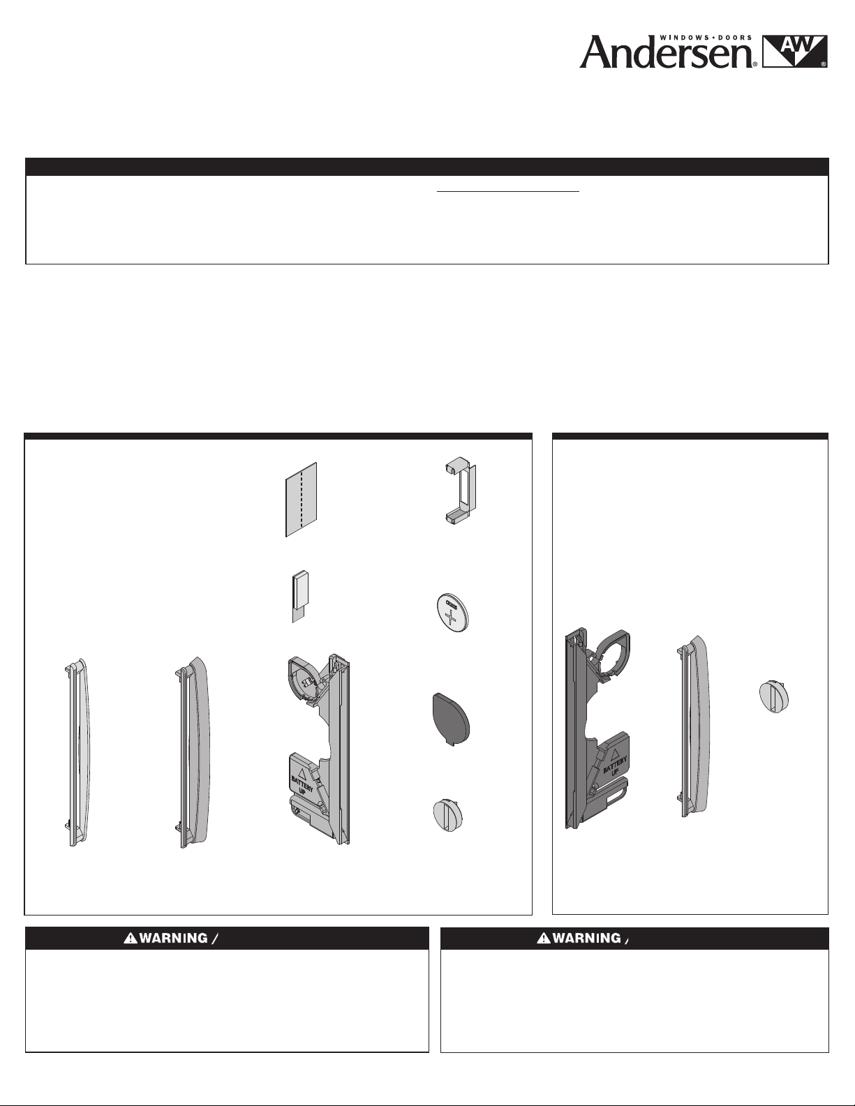
Parts Included / Partes Incluidas
(5) VeriLock Bezel / VeriLock Bezel
(1) VeriLock Sensor / VeriLock Sensor
(3) VeriLock Insect Screen Strike /
VeriLock Insect Screen Strike
(1) Sash Magnet / Sash Magnet
(1) Lock Handle Magnet /
Lock Handle Magnet
(1) Magnet Placement Template /
Magnet Placement Template
(1) CR-2025 Battery / CR-2025 Battery
(1) Battery Cap / Battery Cap
(1) Cleaning Wipe / Cleaning Wipe
Or/ Or
VeriLock Bezel
(Casement Window)
VeriLock Bezel
(Casement Window)
VeriLock Bezel
(Awning Window)
VeriLock Bezel
(Awning Window)
Magnet
Placement
Template
Magnet
Placement
Template
Sash Magnet
Sash Magnet
VeriLock® Sensor
Sensor VeriLock®
Lock Handle Magnet
Lock Handle Magnet
CR-2025 Battery
Batería CR-2025
Battery Cap
Battery Cap
VeriLock Insect
Screen Strike
VeriLock Insect
Screen Strike
Additional Parts for Awning
Windows Only (Sold Separately)
Additional Parts for Awning
Windows Only (Sold Separately)
(1) VeriLock Dummy Sensor/
VeriLock Dummy Sensor
(5) VeriLock Bezel (Awning Window) /
VeriLock Bezel (Awning Window)
(3) VeriLock Insect Screen Strike /
VeriLock Insect Screen Strike
VeriLock Insect
Screen Strike
VeriLock Insect
Screen Strike
VeriLock
Dummy Sensor
VeriLock
Dummy Sensor
VeriLock Bezel
(Awning Window)
VeriLock Bezel
(Awning Window)
Use caution when working at elevated heights and around unit openings.
Follow manufacturers’ instructions for ladders and/or scaffolding. Failure
to do so may result in injury or death.
Sea cauteloso al trabajar en lugares elevados y cerca de las aberturas de
la unidad. Siga las instrucciones del fabricante para el uso de escaleras
y/o andamios. Si no lo hiciera, podrían producirse lesiones o la muerte.
“Andersen” and all other marks where denoted are trademarks of Andersen Corporation and its subsidiary. © 2016 Andersen Corporation. All rights reserved.
“Andersen” y todas las demás marcas que aparezcan son marcas registradas de Andersen Corporation y su subsidiaria © 2016 Andersen Corporation. Todos los derechos reservados.
Follow manufacturers’ instructions for hand or power tools. Always
wear safety glasses. Failure to do so may result in injury and/or
product damage.
Siga las instrucciones del fabricante para el uso de herramientas
eléctricas o manuales. Utilice siempre gafas de seguridad. Si no lo
hiciera, podrían producirse lesiones y/o daños al producto.
9138838 BA -0 1 Revised 03/07/16
Page 2
Batteries carry the risk of re, explosion and burns. Do not recharge,
disassemble, heat above 212 degrees F (100 degrees C) or incinerate.
Dispose of used batteries promptly and properly. Keep away from children.
Les piles représentent un risque d’incendie, d’explosion et de brûlures. Ne
pas recharger, démonter, chauffer à une température excédant 100degrés
C (212degrésF) ou incinérer. Éliminer les piles rapidement et de manière
appropriée. Garder à l’écart des enfants.
Magnetic eld can be harmful to implanted medical device wearers.
Keep magnets away from devices.
El campo magnético puede dañar a personas con dispositivos médicos
implantados. Mantenga los imanes lejos de los dispositivos.
For Awning Units / For Awning Units
Magnets are small parts and, if swallowed, could pose a choking
hazard to young children.
Los imanes son partes pequeñas que, en caso de ingesta, pueden
representar un riesgo de asxia para niños pequeños.
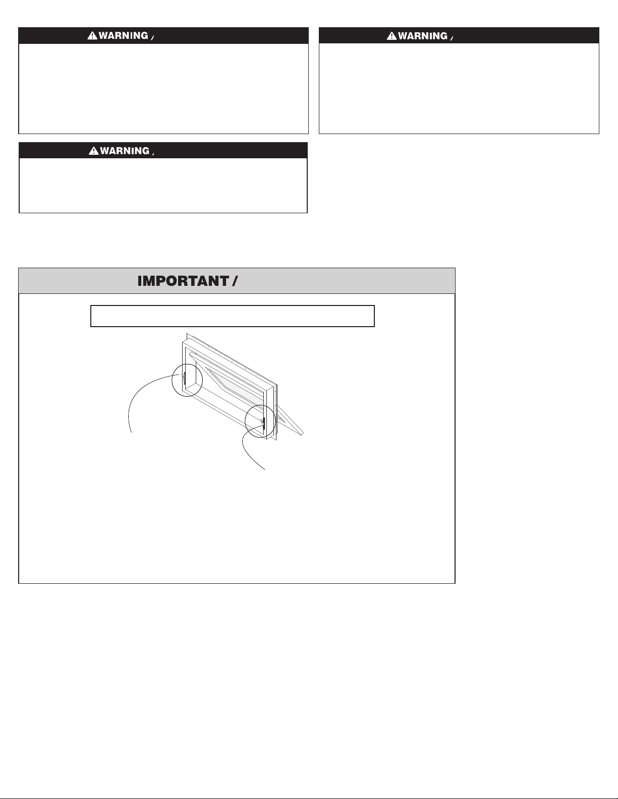
(Interior View)
(Interior View)
NOTE: VeriLock sensor
is installed on the left
lock on awning units, as
viewed from the interior.
NOTE: (Active) VeriLock
sensor is installed on
the left lock on awning
units, as viewed from
the interior.
NOTE: VeriLock dummy sensor
is installed on the right lock on
awning units, as viewed from
the interior. (sold separately)
NOTE: VeriLock dummy sensor
is installed on the right lock on
awning units, as viewed from
the interior. (sold separately)
▶ Left handed casement unit shown in guide. Steps are similar for awning units, unless otherwise noted.
Left handed casement unit shown in guide. Steps are similar for awning units, unless otherwise noted.
9138838
2
Page 3
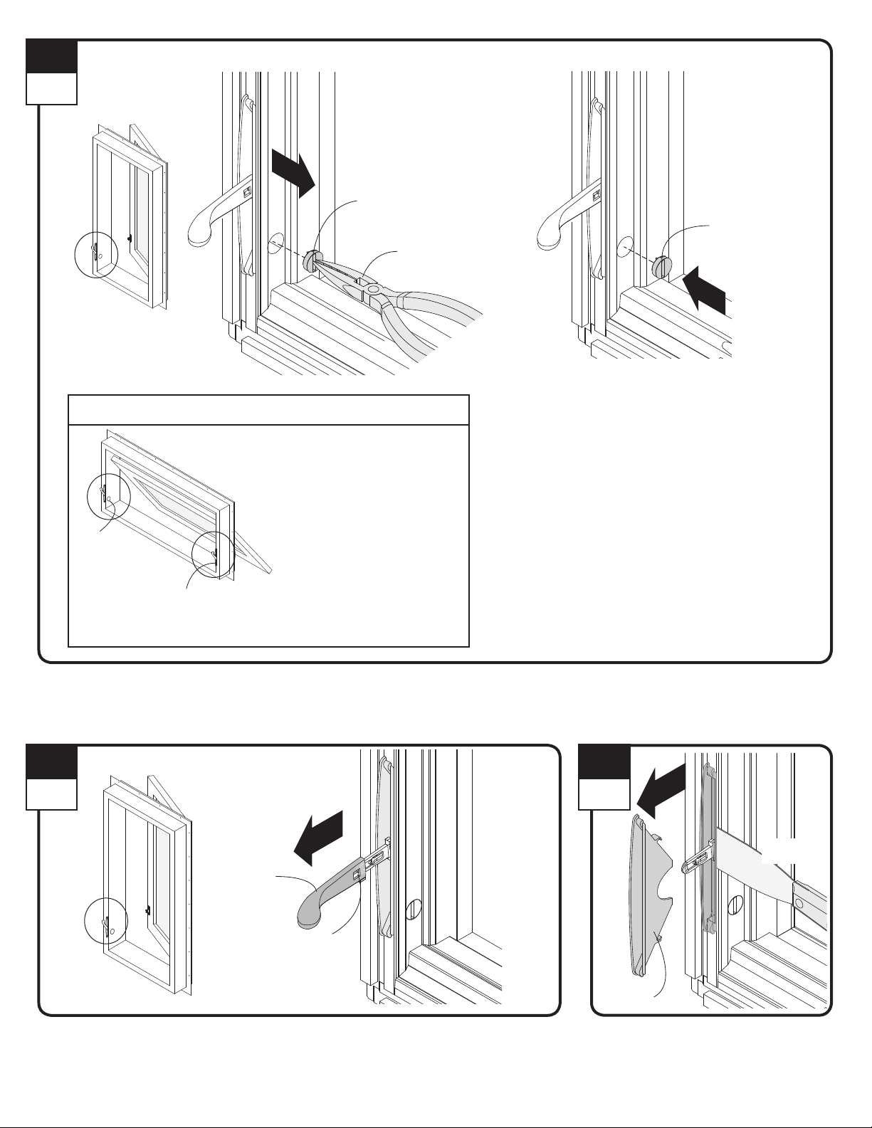
1
Interior
Left Side
Insect Screen
Strike
Left Side
Insect Screen
Strike
For Awning Units / For Awning Units
NOTE: For Awning units, remove
and replace the insect screen
strike on the left side, as viewed
from the interior.
Remove and replace insect
screen strike on right side only if
dummy kit is purchased.
NOTE: For Awning units, remove
and replace the insect screen
strike on the left side, as viewed
from the interior.
Right Side
Insect Screen Strike
Right Side
Insect Screen Strike
Remove and replace insect
screen strike on right side only if
dummy kit is purchased.
Insect Screen Strike
Screen Strike
Needle Nose Pliers
Needle Nose Pliers
VeriLock Insect
Screen Strike
VeriLock Insect
Screen Strike
Remove insect screen (if present). If insect screen strike is located near the lock handle as shown, remove insect screen strike from casement lock
side or awning left lock side and dispose of properly. Insert preferred color VeriLock insect screen strike into same hole. Press rmly into place.
Remove insect screen (if present). If insect screen strike is located near the lock handle as shown, remove insect screen strike from casement lock
side or awning left lock side and dispose of properly. Insert preferred color VeriLock insect screen strike into same hole. Press rmly into place.
2
Interior
Lock
Handle
Lock
Handle
Lock Handle
Hole
Lock Handle
Hole
Position lock handle as shown. Remove lock handle by pressing clip through hole. Save for reuse.
Position lock handle as shown. Remove lock handle by pressing clip through hole. Save for reuse.
3
Interior
Putty Knife
Putty Knife
Bezel
Bezel
Remove bezel using a thin blade putty knife.
Dispose of properly.
Remove bezel using a thin blade putty knife.
Dispose of properly.
9138838
3
Page 4
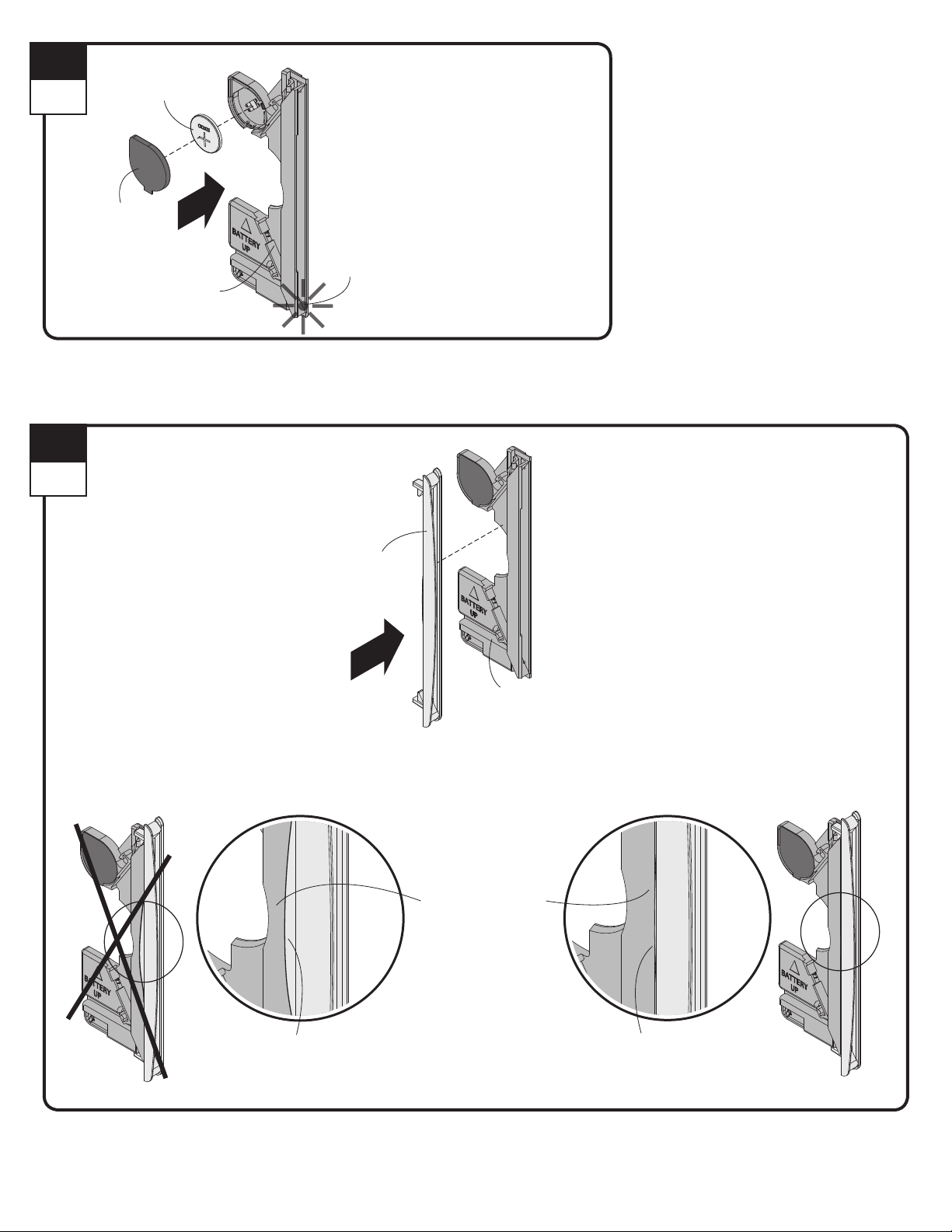
4
Interior
CR-2025 Battery
Batería CR-2025
Battery Cap
Battery Cap
VeriLock Sensor
Sensor VeriLock
Indicator Light
Luz indicadora
Install battery with (+) facing out as shown. Indicator light will illuminate for one (1) second when battery is installed correctly.
Position battery cap over battery with edges tightly sealed. Make sure all cap edges are sealed around the battery ring.
Install battery with (+) facing out as shown. Indicator light will illuminate for one (1) second when battery is installed correctly.
Position battery cap over battery with edges tightly sealed. Make sure all cap edges are sealed around the battery ring.
5
Interior
VeriLock
Bezel
VeriLock
Bezel
Wider edge up.
Wider edge up.
VeriLock Sensor
VeriLock Sensor
Incorrect / Incorrect
VeriLock Assembly
VeriLock Assembly
Gently flex the plastic
VeriLock sensor wall to
outside of the VeriLock
bezel lip as shown.
Gently flex the plastic
sensor wall to outside
of bezel lip as shown.
VeriLock Bezel NOT Seated Properly
(VeriLock bezel lip on outside)
VeriLock Bezel NOT Seated Properly
(VeriLock bezel lip on outside)
Correct / Correct
VeriLock Bezel Seated Properly
(VeriLock bezel lip on inside)
VeriLock Bezel Seated Properly
(VeriLock bezel lip on inside)
Select preferred VeriLock bezel color and attach to VeriLock sensor as shown. Make sure the plastic sensor wall is on the outside of the VeriLock
bezel lip as shown.
Select preferred VeriLock bezel color and attach to VeriLock sensor as shown. Make sure the plastic sensor wall is on the outside of the VeriLock
bezel lip as shown.
9138838
4
Page 5
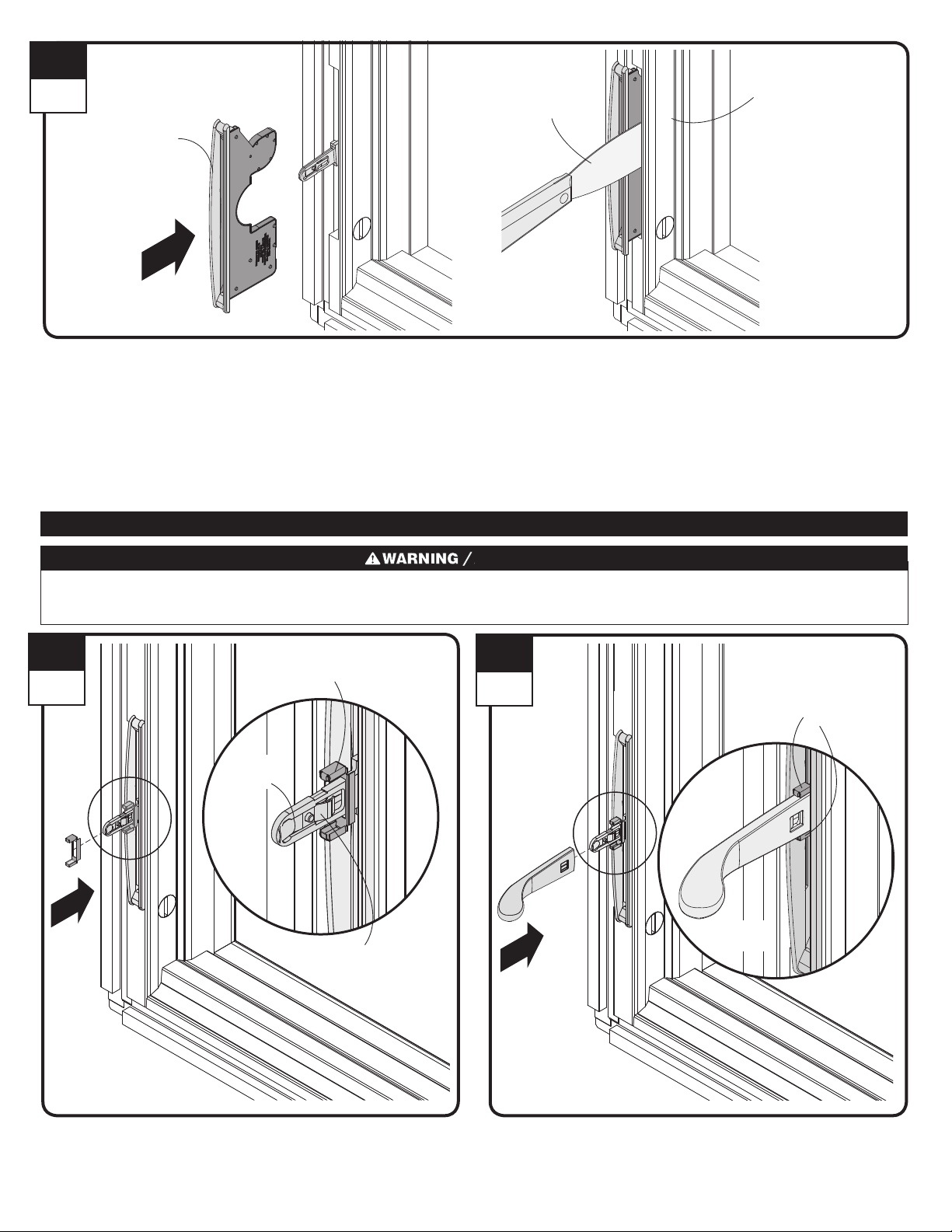
6
Interior
VeriLock Assembly
VeriLock Assembly
Wider edge of
VeriLock bezel
toward side jamb.
Wider edge of
VeriLock bezel
toward side jamb.
Thin Blade Putty Knife
Thin Blade Putty Knife
Trim Stop
Trim Stop
Gently pry trim stop and insert VeriLock assembly into the cavity. VeriLock assembly will click into place when installed correctly.
Gently pry trim stop and insert VeriLock assembly into the cavity. VeriLock assembly will click into place when installed correctly.
Magnet Application/ Magnet Application
Magnets are small parts and, if swallowed, could pose a choking hazard to young children.
Los imanes son partes pequeñas que, en caso de ingesta, pueden representar un riesgo de asxia para niños pequeños.
7
Interior
Lock Lever
Lock Lever
Lock Handle Magnet
Lock Handle Magnet
Detent Spring
Detent Spring
8
Interior
Lock Handle Magnet
Position around lock handle
as shown.
Lock Handle Magnet
Position around lock handle
as shown.
Lock Handle
Lock Handle
Position lock handle magnet on lock lever and slide past the detent
spring.
Position lock handle magnet on lock lever and slide past the detent
spring.
Slide lock handle on lock lever until clip engages and magnets are
positioned around the lock handle as shown.
Slide lock handle on lock lever until clip engages and magnets are
positioned around the lock handle as shown.
Page 6
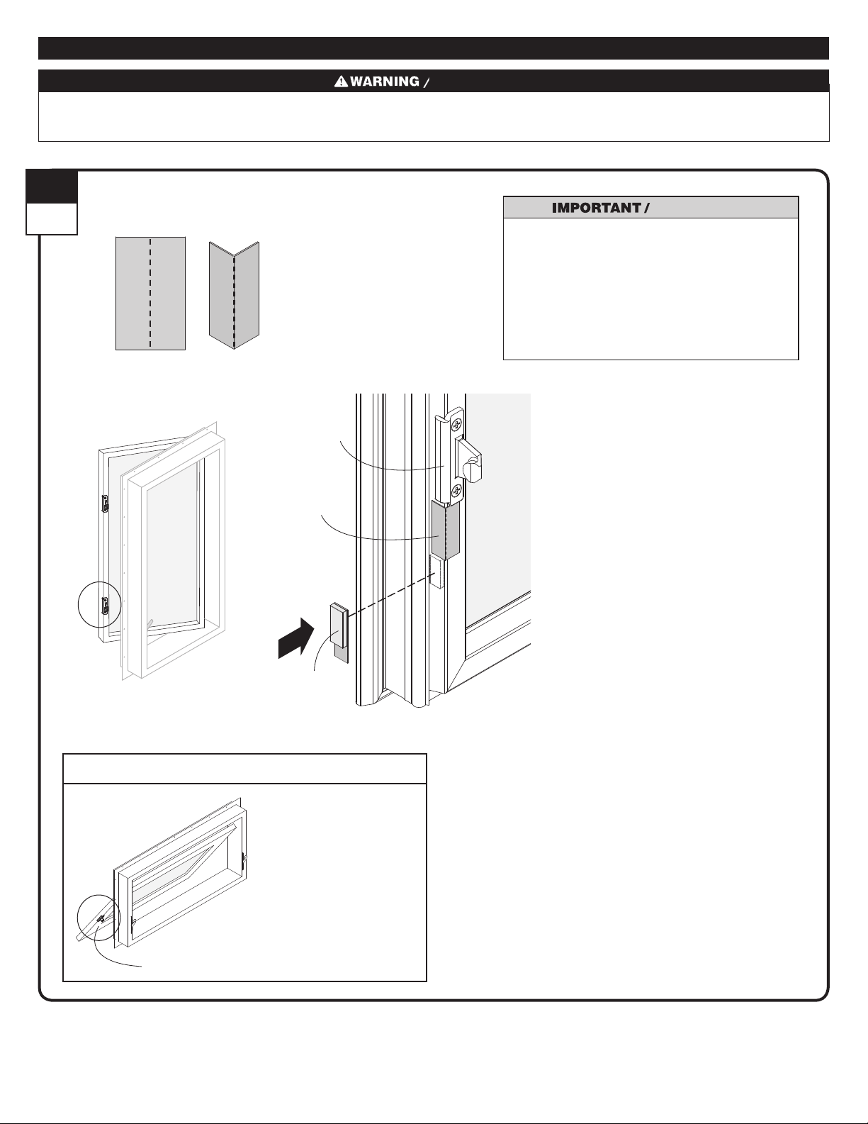
Magnet Application/ Magnet Application
Magnets are small parts and, if swallowed, could pose a choking hazard to young children.
Los imanes son partes pequeñas que, en caso de ingesta, pueden representar un riesgo de asxia para niños pequeños.
9
Interior
Magnet Placement Template
Magnet Placement Template
Bend magnet placement
template 90º at perforation
and position on sash under
keeper as shown.
Bend magnet placement
template 90º at perforation
and position on sash under
keeper as shown.
Keeper
Keeper
Press and hold sash magnet in place for 20-30
seconds when applying to sash. Do not fully close
sash until adhesive tape is completely bonded.
(allow 10-15 minutes for adhesive to bond).
Press and hold sash magnet in place for 20-30
seconds when applying to sash. Do not fully close
sash until adhesive tape is completely bonded.
(allow 10-15 minutes for adhesive to bond).
Magnet
Placement
Template
Magnet
Placement
Template
Sash Magnet
Sash Magnet
For Awning Units / For Awning Units
NOTE: Sash magnet is
installed on sash below the
left side keeper on awning
units, as viewed from the
interior.
NOTE: Sash magnet is
installed on sash below the
left side keeper on awning
units, as viewed from the
interior.
Left Side Keeper
Left Side Keeper
Clean area on sash to receive magnet with cleaning wipe provided. Position template tight to bottom of keeper as shown. Remove adhesive liner
on sash magnet and position tight to bottom edge of magnet placement template as shown. Press firmly in place.
Clean area on sash to receive magnet with cleaning wipe provided. Position template tight to bottom of keeper as shown. Remove adhesive liner
on sash magnet and position tight to bottom edge of magnet placement template as shown. Press firmly in place.
9138838
6
Page 7
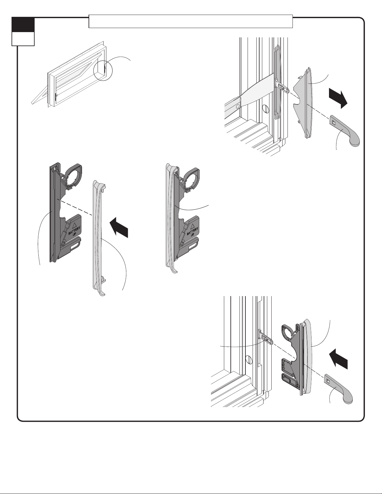
10
Interior
For Awning Units Only / For Awning Units Only
NOTE:
VeriLock dummy sensor (sold
separately) is installed on the
right lock on awning units, as
viewed from the interior.
NOTE:
VeriLock dummy sensor (sold
separately) is installed on the
right lock on awning units, as
viewed from the interior.
VeriLock Dummy
Assembly
VeriLock Dummy
Assembly
VeriLock Bezel seated
properly (VeriLock dummy
sensor wall on outside of
VeriLock bezel lip)
VeriLock Bezel seated
properly (VeriLock dummy
sensor wall on outside of
VeriLock bezel lip)
Bezel
Bezel
Lock Handle
Lock Handle
VeriLock
Dummy Sensor
VeriLock
Dummy Sensor
VeriLock Bezel
(Awning Window)
VeriLock Bezel
(Awning Window)
Lock Lever
Lock Lever
VeriLock Dummy Assembly
VeriLock Dummy Assembly
Wider edge of VeriLock
bezel toward side jamb.
Wider edge of VeriLock
bezel toward side jamb.
Lock Handle
Lock Handle
VeriLock dummy sensor (sold separately)/ VeriLock dummy sensor. (sold separately).
Remove lock handle and bezel from the right lock as viewed from the interior and dispose of bezel properly. Attach the awning window VeriLock
bezel to the VeriLock dummy sensor and insert the VeriLock dummy assembly tight into lock cavity as shown. Slide lock handle on lock lever until
clip engages.
Remove lock handle and bezel from the right lock as viewed from the interior and dispose of bezel properly. Attach the awning window VeriLock
bezel to the VeriLock dummy sensor and insert the VeriLock dummy assembly tight into lock cavity as shown. Slide lock handle on lock lever until
clip engages.
9138838
7
Page 8
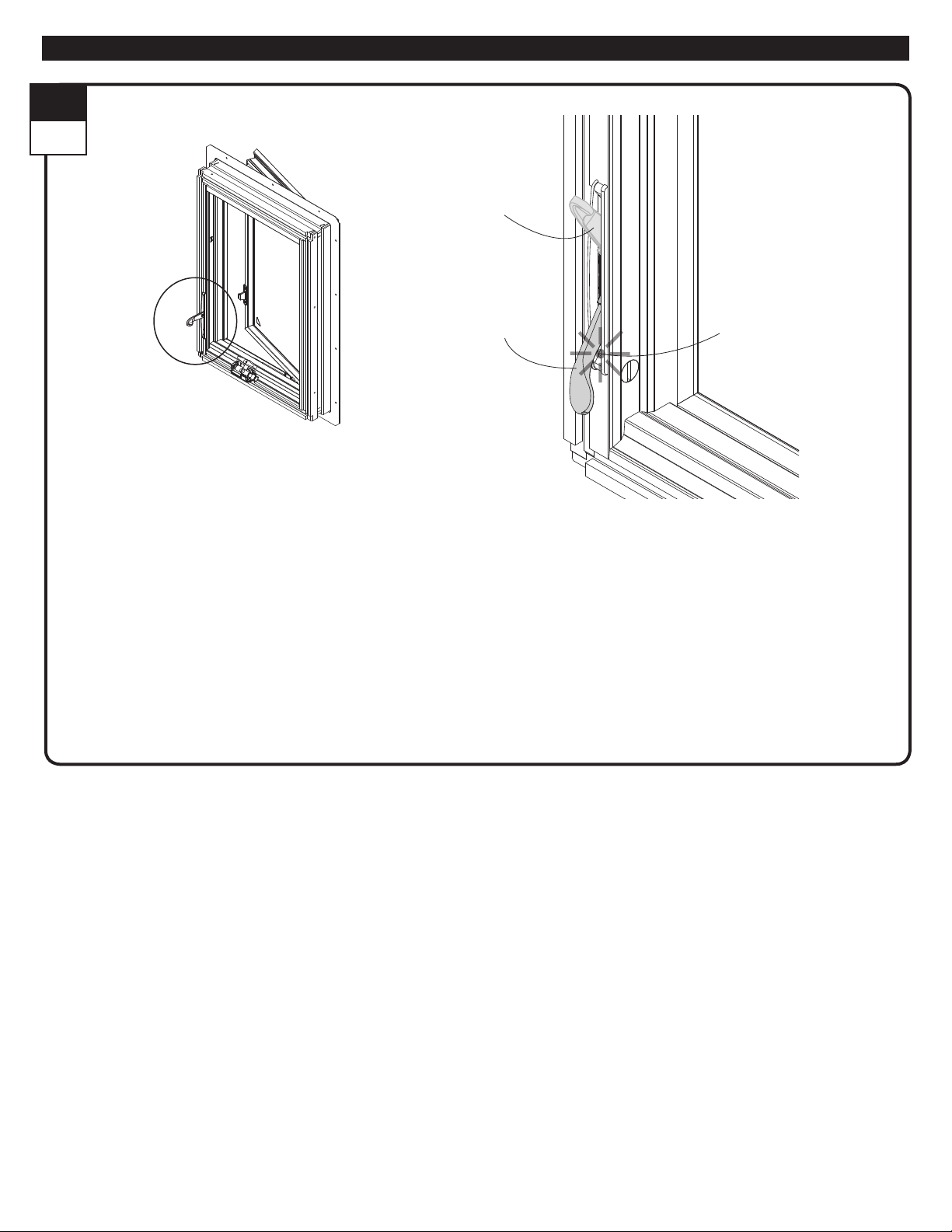
11
Interior
Verify VeriLock Sensor Function / Verique el funcionamiento de sensor VeriLock
Lock Handle
(unlocked position)
Lock Handle
(en posición abierto)
Lock Handle
(locked position)
Lock Handle
(en posición cerrado)
Indicator Light
Luz indicadora
1. Lock window. Indicator light will illuminate for one (1) second.
2. Unlock window. Indicator light will illuminate for one (1) second.
3. Open sash. Indicator light will illuminate for one (1) second.
4. Close sash. Indicator light will illuminate for one (1) second.
1. Lock window. Indicator light will illuminate for one (1) second.
2. Unlock window. Indicator light will illuminate for one (1) second.
3. Open sash. Indicator light will illuminate for one (1) second.
4. Close sash. Indicator light will illuminate for one (1) second.
Verify VeriLock sensor function. If indicator light does not respond as described, verify sensor application and magnet placement.
Verique el funcionamiento del sensor VeriLock. Si la luz indicadora no funciona como se describió anteriormente, verique la aplicación del
sensor y la ubicación del imán.
▶ Procedure is complete.
El procedimiento se ha completado.
Refer to monitoring system of your choice for sensor enrollment. /
Consulte el sistema de monitoreo de su elección para el registro del sensor.
For maintenance information, please visit http://www.andersenwindows.com/verilock and consult with the VeriLock user guide.
Para obtener información de mantenimiento, visite http://www.andersenwindows.com/verilock y consulte con la guía del usuario de VeriLock.
9138838
8
Page 9

Regulatory Statements / Normas reglamentarias
Federal Communications Commission (FCC)
Part 15 Statement
This device complies with FCC Rules Part 15. Operation is
subject to the following two conditions: (1) This device may not
cause harmful interference. (2) This device must accept any
interference that may be received, including interference that
may cause undesired operation.
Industry Canada (IC) RSS Statement
This device complies with Industry Canada license-exempt RSS
standard(s). Operation is subject to the following two conditions:
(1) This device may not cause interference, and (2) This device
must accept any interference, including interference that may
cause undesired operation of the device.
Le présent appareil est conforme aux CNR d'Industrie Canada
applicables aux appareils radio exempts de licence.
L'exploitation est autorisée aux deux conditions suivantes: (1)
I'appareil ne doit pas produire de brouillage; (2) I'utilisateur de
I'appareil doit accepter tout brouillage radioélectrique subi,
méme si le brouillage est susceptible d'en compromettre le
fonctionnement.
Changes or modifications not expressly approved by Andersen
may void the user's authority to operate the equipment.
9138838
9
Page 10

This page has been intentionally left blank.
Página intencionalmente en blanco.
9138838
10
 Loading...