

Page 1
Assembly Instructions
Funbrella Shark
Funbrella Classic
Funbrella® Classic
Funbrella® Shark
12’ and 20’ Diameter
Please read all assembly/installation instructions before the installation or removal of this product.
1100 Burch Drive, Evansville, IN 47725
Phone: 1-800-255-5552 • 812-867-2421 • Fax: 812-867-1429
Email: custdiv@anchorinc.com • www.anchorinc.com
EC4189
Quality, Craftsmanship and Service since 1892
FUNB-0510
Rev of 11-11-10
Page 2
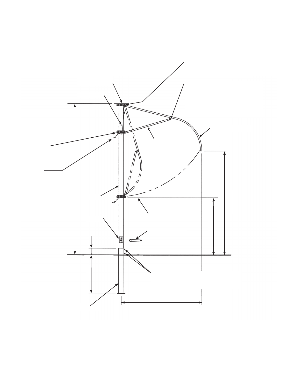
12’-0” DIAMETER FUNBRELLA FRAME
5/16”-18 x 1 1/2” LONG HEX
BOLT & LOCK NUT (8) FOR
TOP PLUG
(PLASTIC CAP)
STOP BOLT
ATTACHING BOWS
5/16”-18 x 7/8” LONG CARRIAGE
BOLT & ACORN NUT (8) FOR
ATTACHING BRACES TO BOWS.
CAUTION: PLACE EYE END OF
BRACE BETWEEN EARS OF
RAFTER CLAMP. (SEE PAGE 4)
5/16”-18 x 1 1/2” LONG
BOLT & LOCKNUT
(8) FOR ATTACHING
BRACES.
USE SAFETY PIN
WHEN UMBRELLA
IS OPEN.
11’- 3”
POLE
WINCH
6”
BRACE (8)
APPROX. CLOSED
POSITION
WINCH HANDLE
FINISH GRADE
BOW RAFTER (8)
7’ -1”
APPROX
4’- 2”
2’- 10”
GROUND SLEEVE
3/8”-16 X 5” HEX HEAD CAP SCREW
WITH CAP NUT (2) FOR ATTACHING
POLE TO SLEEVE.
6’- 0”
2
Page 3
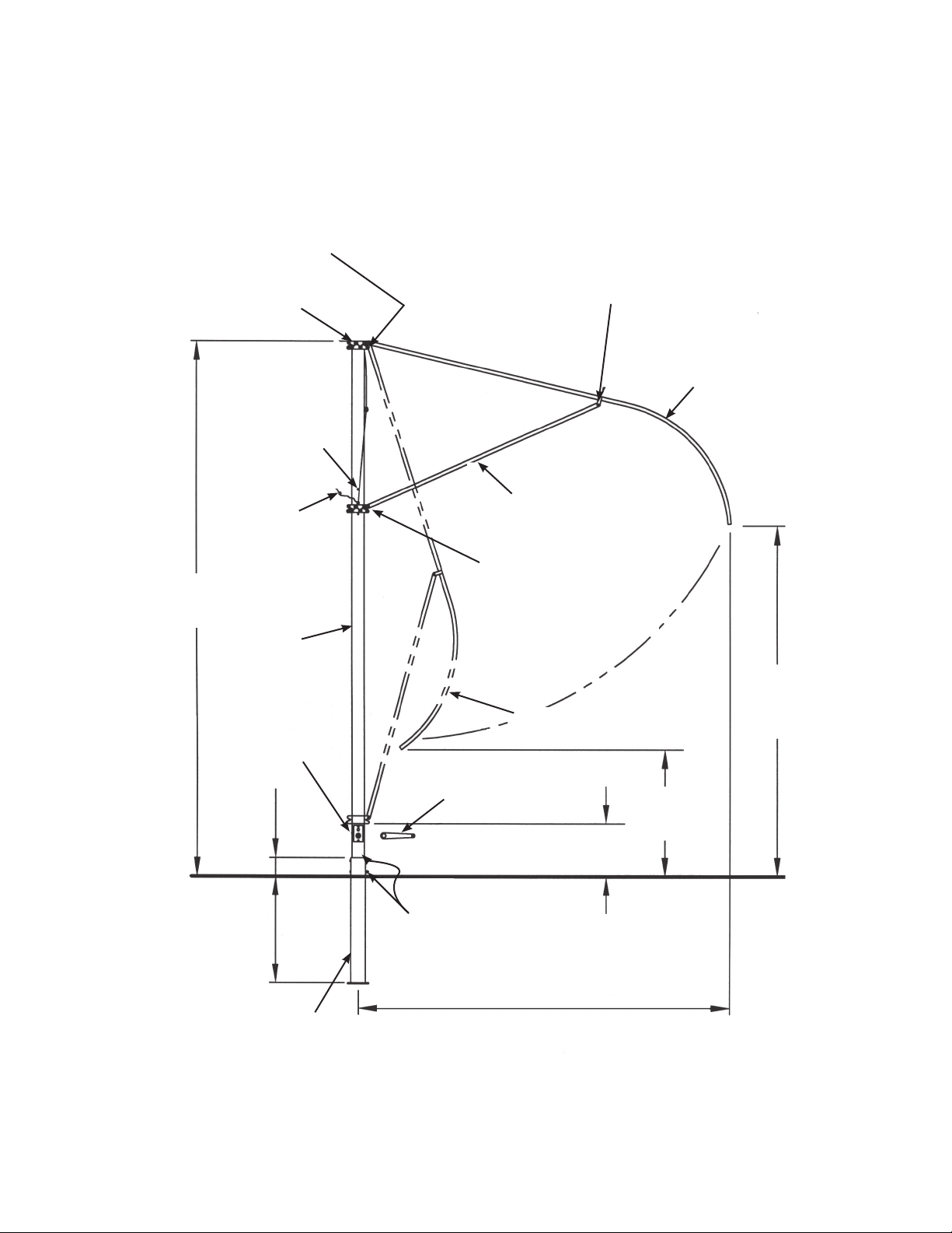
20’-0” DIAMETER FUNBRELLA FRAME
5/16”-18 X 1 1/2”
LONG HEX BOLT &
LOCKNUT (14) FOR
ATTACHING BOWS.
TOP PLUG
(PLASTIC CAP)
STOP BOLT
USE SAFETY PIN
WHEN UMBRELLA
IS OPEN
14’ -3”
POLE
5/16”-18 X 7/8” LONG CARRIAGE BOLT &
ACORN NUT (14) FOR ATTACHING BRACES
TO BOWS. CAUTION: PLACE EYE END
OF BRACE BETWEEN EARS OF RAFTER
CLAMP. (SEE PAGE 4).
BRACE (14)
5/16”-18 x 1 1/2” LONG
HEX BOLT & LOCKNUT
(14) FOR ATTACHING
BOWS.
BOW RAFTERS (14)
WINCH
6”
2’- 10”
GROUND SLEEVE
APPROX. CLOSED
POSITION
WINCH HANDLE
3’- 3”
FINISH GRADE
3/8”-16 X 5” HEX HEAD CAP SCREW
WITH CAP NUT (2) FOR ATTACHING
POLE TO SLEEVE.
10’- 0”
1’- 6”
8’ -9”
3
Page 4

Warning: Do not install groundsleeve or center pole where they
may be in contact with water
from swimming pool or any other
body of water.
Raise Pole and insert into Ground Sleeve.
Align holes and fasten with (2) 3/8” x 5” bolts
and cap screws. Rotate lower casting so
cable is parallel with pole.
4
Page 5

ATTACH RAFTERS AND BRACES
3
Attach braces to clamp on each rafter with 5/16” x
7/8” carriage bolt and acorn nut.
Attach rafter to top casting and brace to lower casting with 5/16” x 1 1/2” cap screws and lock nuts.
Place top plug onto end of pole.
CAUTION
Position eye ends of braces between ears of rafter
clamps (see detail) and be aware of rafter ends
when working under the frame to avoid physical
injury.
TOP CASTING
RAFTER
Over tightening of nuts can result in frame damage.
When attaching rafters and braces, tighten to where
one and a half threads are exposed. This allows
free movement of parts.
PLACE TOP ON FRAME
4
Using handle, crank winch clockwise to open frame
partially. Place top with leather patch covering top
plug and drape over frame.
For Sunbrella Tops, pull hooks to ends of rafters
and through cap. Snap boot. Crank winch to open
fully and insert safety pin.
For UV Shadecloth Tops, pull hook to end of one
rafter and through cap. Proceed next to the rafter
directly opposite the first rafter. Using short bursts,
pull the fabric down until fabric is loosened enough
to reach the end of the rafter. Proceed around the
frame using the short-burst method as required.
Fasten Velcro ties around rafters. Crank winch to
open fully and insert safety pin.
WARNING:
When operating winch, handle must be on winch nut
and under control of operator to prevent rapid closure of FUNBRELLA.
BRACE
LOWER
CASTING
TOP
WINCH
HANDLE
IMPORTANT
Proper installation suitable to site conditions is the
responsibility of the installer.
SNAP
RAFTER
HOOK
RAFTER
BOOT
RUBBER
CAP
RAFTER
CASTING
POLE
CABLE
SAFETY
PIN
For removal of pole, reverse steps 1 through 3 to
prevent frame damage.
CAUTION
When high wind conditions are expected, or
when lowering the Funbrella overnight, close the
FUNBRELLA and tie the bows together to
minimize movement that can cause accelerated
wear. (See warning on page 7)
5
Page 6

WINCH ASSEMBLY
5/8” WASHER
5/8” BUSHING
RETAINING
RING
RATCHET
PAWL
LARGE OD
WASHER
3/8-16 HEX
JAM LOCK
NUT
SPACER
DRIVE
SHAFT
ASS’Y
BRAKE LINING
PLATE
SPRING HOOK
STUD
RATCHET
WHEEL
CURVED
PLATE
“A”
FLAT HEAD
PHILLIPS
SS SCREW
(TYP. 2)
HANDLE
NUT
CURVED
SPRING
WASHER
RETAINER
NUT
CURVED
PLATE
CUT-AWAY VIEW FRONT VIEW
SPRING
6
Page 7

DO NOT INSTALL GROUNDSLEEVE OR CENTER POLE WHERE THEY MAY BE IN
CONTACT WITH WATER FROM SWIMMING POOL OR ANY OTHER BODY OF WATER.
STORAGE BAG IS FOR USE ONLY WHEN TOP IS REMOVED FROM FRAME. DO NOT
STORE FUNBRELLA FABRIC TOP ON FRAME IN STORAGE BAG.
FABRIC SHOULD BE REMOVED FROM FRAME WHEN FRAME IS LOWERED FOR AN
EXTENDED PERIOD OF TIME. WHEN FRAME IS LOWERED FOR SHORTER PERIODS OF
TIME IT IS IMPORTANT TO “SECURE FRAME RAFTERS AND BRACES” TO MINIMIZE
MOVEMENT AND PREVENT FABRIC AND FRAME DAMAGE.
THE FUNBRELLA FRAME AND TOP ARE DESIGNED FOR YEARS OF EXTENDED WEAR
WHEN THESE INSTRUCTIONS ARE CAREFULLY FOLLOWED.
ANCHOR INDUSTRIES, INC.
1100 BURCH DR., PO BOX 3477, EVANSVILLE, IN 47733-3477
PHONE: 812-867-2421 FAX: 812-867-1429
TOLL FREE: 1-800-255-5552
7
Page 8

EVANSVILLE, INDIANA
PHONE NUMBER
812· 867· 2421
TOLL FREE
800· 255· 5552
FAX NUMBER
812· 867· 1429
Anchor products are of superior design and operate best within the parameters of these instructions. It is imperative
that the instructions be carefully read and COMPLETELY FOLLOWED. Please read installation instructions before the
installation or removal of this product. Installation instructions are available online at www.anchorinc.com or by calling
1-800-255-5552.
CAUTION:
1. For each installation, the installer is solely responsible for evaluating the site and the proper securing method
determined. Some soils require different staking or securing than that provided with the structure. Due to this
variety of soil conditions, these are the manufacturer’s suggested sequence of installation procedures. Anchor’s
responsibility is limited to the manufacture of the fabric and frame parts and materials. We are not responsible for
methods that installers may choose to erect and secure the structure to the ground.
2. The mounting method suggested in the installation instructions does not necessarily meet all or any relevant codes
on the site of the installation. The method suggested will, in many cases, keep the structure erected, however,
due to various soil conditions; this method may be insuffi cient to keep the structure secure in high winds. It is
the installer’s responsibility, not the manufacturer, to determine the appropriate method of securing the structure
to meet the necessary wind loads on the site. Regardless of the mounting method we suggest, we make no
representation or warranty as to whether the mounting method suggested will meet the local code. Anchor does
not, nor can it make any suggestions, representation, or warranties about the adequate mounting required at each
specifi c installation site.
3. Inasmuch as the weather is unpredictable, good judgment and common sense must be incorporated within
installation guidelines. It is the responsibility of the installer/maintainer to determine the severity of the weather,
proper time and method of installation and/or erection and disassembly. Note: We recommend that snow and
ice be removed from the tent surface as soon as possible because accumulation will damage the fabric
or frame structure. Please consult with our Engineering Department about the maximum loads for each
product.
This product has been manufactured for use as a temporary sunshade structure. For the safety of all occupants,
evacuation is recommended if threatening weather occurs, or if there is any doubt concerning the safe use of this
product.
4. Proper safety equipment should be used at all times to insure a safe installation and take down. We suggest a
careful evaluation be made to determine safety equipment needed, such as hard hats, steel-toe shoes, safety
glasses and other as required. It is our desire that all installations are safe. Please be aware of hidden dangers
both underground, i.e., gas lines, water lines, electrical lines, etc. and above the structure such as power lines and
telephone lines.
5. Anchor stands behind its products in accordance with its standard Terms and Conditions of sale. A copy of our
Terms and Conditions of Sale can be obtained by contacting Anchor at the telephone number and/or address on
this document.
28.1 Alternate 04-29-10
 Loading...