


Explorer Pro Sound System Owners Manual
A Message from the President
Congratulations on purchasing an Anchor Audio sound system, the choice of thousands of satisfied customers including the White House, prestigious universities, school districts nationwide, police and fire departments, and all branches of the U.S. Military. Our products are made of the finest materials and built with pride in the U.S.
We’ve incorporated the latest technology into your sound system yet kept it simple to use. Just take a few minutes to review this manual to ensure the maximum enjoyment of your Anchor system. Or, you can view a demonstration video complete with a trouble shooting section at www.anchoraudio.com.
Feel free to call our friendly customer support staff at 1-800-ANCHOR1 with any questions. We love to hear from our customers.
Janet Jacobs – President |
|
on behalf of all Anchor Employees |
|
CONTENTS |
|
GETTING STARTED................................................................................................................... |
1 |
BASIC SYSTEM OPERATION / SPEAKER STAND SETUP.............................................................. |
2 |
CONNECTING SOUND SYSTEM / CONTROLLING FEEDBACK....................................................... |
3 |
OPERATING THE BUILT-IN UHF WIRELESS RECEIVER / CERTIFICATION......................................... |
4 |
OPERATING THE WIRELESS MICROPHONE/TRANSMITTER.......................................................... |
5 |
CARING FOR YOUR BATTERY.................................................................................................... |
6 |
IMPORTANT SAFETY INFORMATION.......................................................................................... |
7 |
HAVING TROUBLE WITH YOUR SOUND SYSTEM? / TECHNICAL SPECS........................................ |
8 |
MADE IN USA
SIX YEAR WARRANTY
GETTING STARTED
Please check your new unit carefully for any damage which may have occurred during shipment. Each Anchor product is carefully inspected at the factory and packed in specially designed boxes for safe transport.
Notify the freight carrier immediately of any damage to the shipping box or product. Repack the unit
in the original box and wait for inspection by the carrier’s claim agent. Notify your dealer of the pending freight claim.
NOTE: All damage claims must be made with freight carrier!
RETURNING SYSTEMS FOR SERVICE OR REPAIR
For service or repair, please contact the dealer you purchased your system from or visit www.AnchorAudio.com to fill out an
RA (Return Authorization) form. If your system is still under warranty, you will receive an RA Number with instructions to follow. All shipments to Anchor Audio must include an RA number and must be shipped prepaid. C.O.D. shipments and shipments without an RA number will be refused and returned at your expense.
IMPORTANT: Save the shipping box & packing materials, they were specially designed to ship your unit!
The Explorer Pro comes with a six year warranty, and all Anchor Audio batteries, and wireless come with a two year warranty.
1
For System Setup & Operation Videos Visit Our Website: www.anchoraudio.com

Explorer Pro Sound System Owners Manual
BASIC SYSTEM OPERATION
NOTE: Fully Charge Batteries Before First Use!
1.Set all Input Level Controls to minimum & Tones Controls to flat or the middle setting before turning your system on
2.Plug a wired microphone into the MIC 1 or MIC 2 jacks and/or plug an audio source into the LINE-IN jack
3.Switch POWER to ON, the BATTERY LED will light
4.Slowly increase the Level Control for the input jacks used to the desired volume
5.Adjust BASS & TREBLE controls to desired sound quality
IMPORTANT: Make all connections with shielded cables to avoid hum, buzzing or interference.
SPEAKER STAND SETUP
1.Loosen the Lower Collar Knob
2.Separate the stand legs until the leg support Cross Braces are parallel to the floor
3.Tighten the Lower Collar Knob
4.Loosen the Upper Collar Knob and extend the center pole
5.Adjust height and retighten the Upper Collar Knob
6.Place your Anchor sound system on the stand
UPPER
COLLAR LOWER KNOB COLLAR
KNOB 

CROSS BRACES
Speaker Stand Adapter
The 1.5” diameter Speaker Stand Adapter lets you mount the Explorer on a speaker stand.
1.Slide Speaker Stand Adapter into slot on Explorer PRO bottom
2.Tighten screw to secure adapter
3.Place unit on stand carefully
4.Tighten screw on Adapter collar securing Explorer PRO on stand
BACK PANEL OF EXP-7500U2
|
LINE OUT - OUTPUT JACK |
|
Balanced 1/4” – provides a combined |
|
output of all active system inputs |
|
Record your presentation or connect to |
WIRELESS RECEIVERS 4 |
another powered sound system |
(see page 6) |
|
RX INDICATOR LIGHTS FOR WIRELESS RECEIVER 1
A solid red light on one of the RX Indicator Lights indicates that the sound system is getting good reception with the wireless microphone
A solid red light on both RX Indicator Lights indicates that the sound system is a optimum reception with the wireless microphone
RX INDICATOR LIGHTS FOR WIRELESS RECEIVER 2
WIRELESS MICROPHONE 1 LEVEL CONTROL
Adjust knob to control wireless microphone levels
WIRELESS MICROPHONE 2 LEVEL CONTROL
AC POWER CORD INLET
|
LINE IN |
|
|
|
|
|
LINE IN |
|
L |
R |
VOLUME |
WIRELESS 1 |
WIRELESS 2 |
|
|
|
LINE OUT |
|
TREBLE |
9 |
9 |
|
|
|
|
||
|
|
|
BASS |
|
|
|
MIC 1 |
VOLUME |
VOLUME |
|
MIC 1 |
|
|
|
|
|
|
|
VOLUME |
|
|
|
MIC 2 |
|
|
|
MIC 2 |
|
|
|
VOLUME |
|
|
|
MUSIC |
|
CHARGE STATUS |
|
SPEECH |
|
|
|
VOICE |
|
BATTERY EMPTY |
|
OVER |
|
|
|
|
|
OFF |
|
|
POWER INLET |
POWER |
|
|
100-240 VAC, 47-63 Hz |
|
|
|
(250 WATTS MAX) |
|
|
|
|
ON |
|
SPEAKER OUT |
|
|
|
|
WARNING: TO REDUCE THE RISK OF FIRE |
|
|
|
OR ELECTRIC SHOCK, DO NOT EXPOSE |
|
|
|
THIS EQUIPMENT TO RAIN OR MOISTURE. |
|
|
|
POWER SWITCH |
BATTERY LEVEL |
|
INDICATOR LIGHT |
||
|
||
|
(AC/DC only) |
CHARGE INDICATOR LIGHT (AC/DC only)
MADE IN USA
SIX YEAR WARRANTY
LINE IN - INPUT JACKS
The 1/8” (3.5 mm) jack input is used to hook up an iPod, a portable CD/ MP3/ tape player, laptop computer, or similar external
audio source
The 1/4” unbalanced input can be used for other communication devices including a mixer or daisy chaining together multiple Explorer speakers
LINE IN LEVEL CONTROL
TONE CONTROLS - BASS/TREBLE
WIRED MIC LEVEL CONTROLS
MUSIC/ SPEECH BUTTON
In situations where you’re speaking to a larger crowd or in a noisy environment, just push the Music/Speech button in and give your voice an added boost
To return back to normal use, just push the Music/Speech button again
VOICE OVER BUTTON
Push the “Voice Over” button in to have the music automatically
lowered when you speak through a connected microphone
Music will return to original level when mic use/speaking stops
SPEAKER OUT -
OUTPUT JACK
Connect the system to a Explorer PRO unpowered companion speaker
2
For System Setup & Operation Videos Visit Our Website: www.anchoraudio.com
Explorer Pro Sound System Owners Manual
CONNECTING TWO OR MORE EXPLORER PRO SOUND SYSTEMS
USING A EXPLORER PRO UNPOWERED COMPANION SPEAKER (EXP-7501)
Connect one end of a speaker cable (SC-50NL) to the SPEAKER OUT jack on the back of a powered Explorer PRO sound system. Connect the other end to the jack labeled IN on the back of a Explorer PRO unpowered companion speaker.
NOTE: AC power is not required for an unpowered companion speaker.
USING 2 POWERED EXPLORER PRO SOUND SYSTEMS
This method uses the line-output feature of your Explorer PRO sound system. Connect a speaker cable (1/4” phone) from the LINE OUT jack on the first powered Explorer PRO to the LINE IN jack on the second powered Explorer PRO. Set the volume of the second Explorer PRO to maximum so that full volume control will be at the first or primary sound system.
NOTE: The line-output feature can also be used to send the signal to a sound system in a different room or a separate recording device.
SETTING UP YOUR EXPLORER PRO SOUND SYSTEM
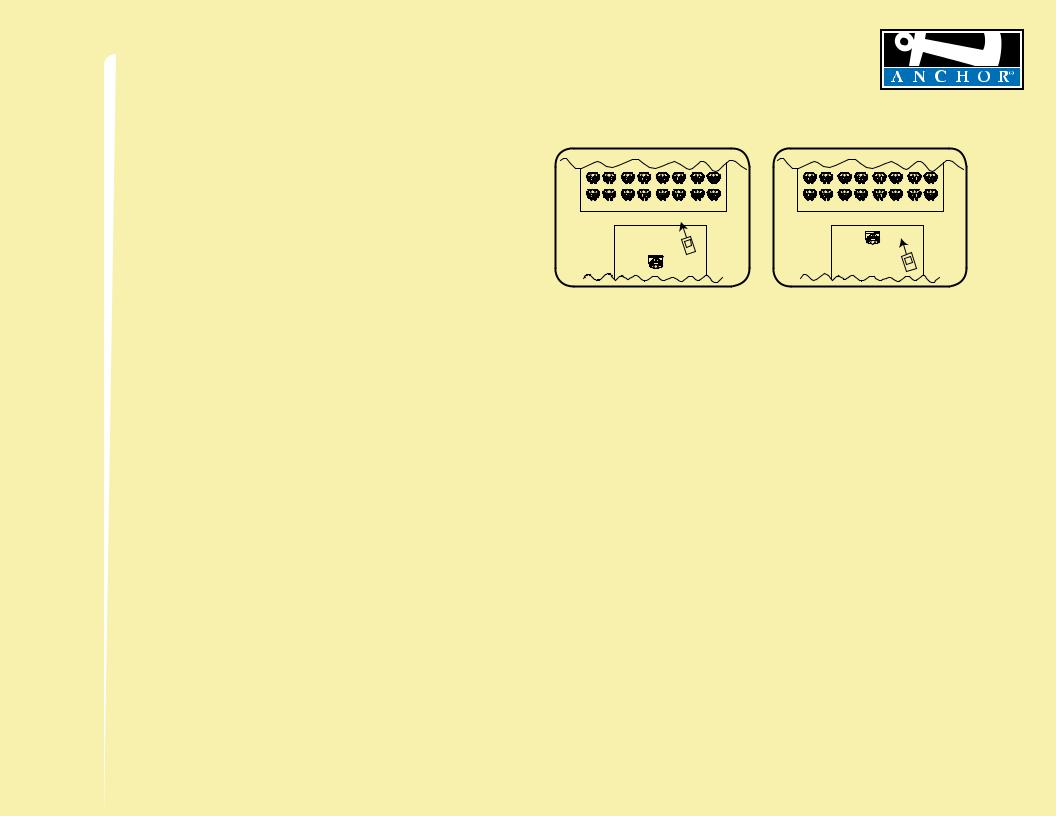
We recommend placing your sound system between the audience and the presenter, facing the audience and raised above their heads using a speaker stand or table. This benefits listeners in the rear of the crowd, minimizes the risk of overpowering those in the front and helps prevent feedback by keeping microphone users behind the sound system.
SINGLE SYSTEM PLACEMENT
Place your unit along the least trafficked aisle pointing towards the center of the audience.
MULTIPLE SYSTEM PLACEMENT
Place units along aisles pointing just off the audience center line, over the crowds head. With the sound system placed properly it should provide sufficient coverage.
MADE IN USA
SIX YEAR WARRANTY
CORRECT SYSTEM PLACEMENT |
|
WRONG SYSTEM PLACEMENT |
|
|
|
|
|
|
CONTROLLING FEEDBACK
Feedback, a howling noise or shrill sound, is self-generated by the sound system. It’s caused by a microphone picking up the sound coming from the speaker and then re-amplifying it. Once a feedback loop starts it continues until the system is adjusted.
FEEDBACK CAUSES
•Microphone too close, pointing towards or in front of speaker
•Volume setting is too loud for room
•Sound reflecting off hard surfaces
AVOIDING & ELIMINATING FEEDBACK
•Point microphone in a different direction
•Keep microphone away from the speaker
•Place speaker in FRONT of the microphone
•Reduce the sound system volume levels
CAUTION: Feedback can damage your equipment & may be hazardous to hearing.
3
For System Setup & Operation Videos Visit Our Website: www.anchoraudio.com
 Loading...