

Page 1
Assembly Instructions
Funbrella
Please read all assembly/installation instructions before the installation or removal of this product.
EVANSVILLE, IN
1100 Burch Drive, Evansville, IN 47725
Phone: 800-322-8368 • 812-867-2421 • Fax: 812-867-4636
Email: oad@anchorinc.com • www.anchorinc.com
® Palm
EC4413
Quality, Craftsmanship and Service since 1892
FunPalm 0811
Rev. 0413
Page 2
1
Page 3
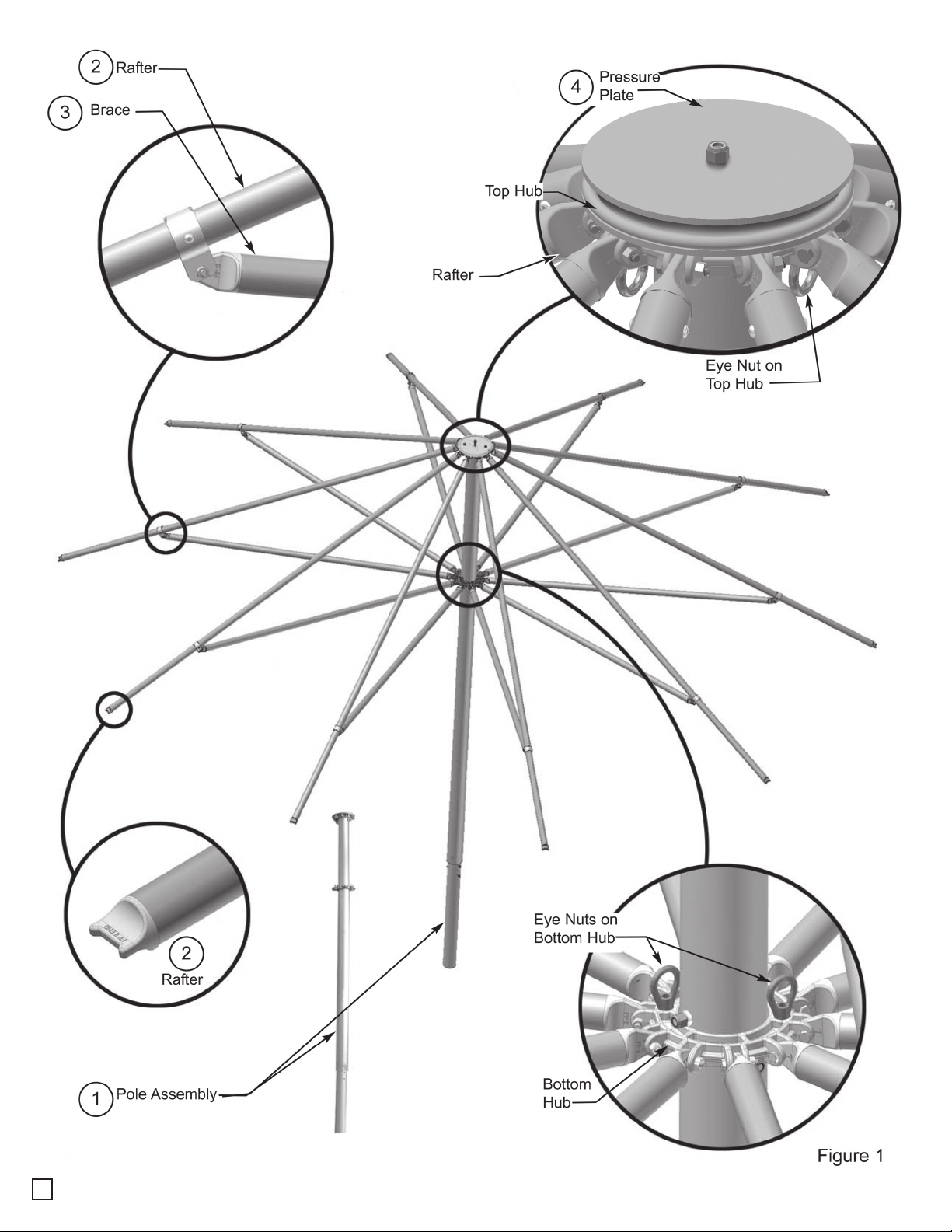
FUNBRELLA PALM PARTS LIST
ITEM NO.
1
2
3
4
5
6
7
8
92
QUANTITY DESCRIPTION
10 Rafters
10 Braces
20 3/8” x 1 3/4” Hex Head Bolt
10 3/8” x 1 1/4” Hex Head Bolt
30 3/8” Lock Nut
1 Pole Assembly
1 Pressure Plate
2 3/8” x 5” Hex Head Bolt
3/8” Cap Nut
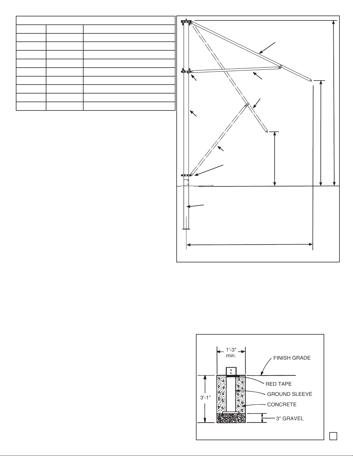
Bottom Hub in
Open Position.
CenterPole
Rafter in Open
Position.
Brace in Open
Position
Rafter in Closed
Position.
13’-6”
MANPOWER REQUIRED
Two experienced installers should be able to assemble
a Funbrella Palm top & frame in two hours.
INSPECT SITE - CAUTION
Consult local Utility Company prior to installation.
Prior to assembly be sure to look around for obstacles, pipes, wires and etc.
LAYOUT & CHECK
Use parts list for a quick identification and check list
for proper quantities.
TOOLS REQUIRED
9/16” Wrench • 5/8” Wrench • 3/4” Wrench
(2) 10’ Stepladders
(1) 16’ Extension Ladder
Post Hole Digger (optional...required only to dig
hole for ground sleeve)
(2) Cable Come-A-Longs (minimum 800 lb. rating,
minimum 10’-0” pull) - sold separately
8’-6”
Brace in Closed
Position.
Bottom Hub in
Closed Position.
Finish Grade
Ground Sleeve
10’-0”
4’-4”
Figure A
Warning: Do not install groundsleeve
or center pole where they may be in
contact with water from swimming
pool or any other body of water.
SET GROUND SLEEVE (SOLD SEPARATELY)
Dig a 1’-3” minimum diameter hole 3’-1” deep or as
required by soil conditions or local code. Add 3” of
gravel. Insert ground sleeve with 6” square plate on
bottom. Ground sleeve is marked with red tape indicat-
ing finished grade level.
(Figure B)
Plumb sleeve and brace into position during concrete
pour.
Fill concrete to cover red tape. Allow to dry for 72
hours before mounting Funbrella Palm center pole.
Figure B
2
Page 4

STEP 1
Set Center Pole Assembly into ground sleeve and
secure with (2) 3/8” x 5” Bolts, and (2) 3/8” Cap Nuts.
(Items # 8 & 9 on Parts List - Page 2.)
Pole Assembly
1
Top hub
(Figures 1a & 1b)
After raising pole, remove bolt, nut and spacers under
bottom hub and set aside for later use. Carefully slide
the hub to the bottom of the pole.
1
8
Ground
Sleeve
8
9
9
Bottom Hub
See Figure 1b
Figure 2a
Figure 1a
7
2
5
Hub on Pole
Assembly
Figure 1b
STEP 2
Using extension ladder, install rafters to top hub with 3/8” x 1 3/4”
Bolts (Item 5) and 3/8” Nuts (Item 7).
Important: Install last two rafters at the same time. To avoid
interference, insert Bolt (Item 5) into hole, thru rafter with end of
bolt flush to edge of casting. (Figure 2a)
Then, insert last bolt into last hole and thru rafter. (Figures 2b &
2c)
Now place nuts on bolts and tighten - do not over-tighten.
(Figure 2d)
Examine bottom hub to be sure it is rotated so that eyenuts on
bottom hub are in-line with eyenuts on top hub.
Repeat the installation process with braces (Items 3) onto bottom
hub on pole assembly.
3
Figure 2b
Figure 2c
Figure 2d
Page 5

STEP 3
Assemble rafters (Item 2) to braces (Item
3) using 3/8” x 1 3/4” Bolts (Item 6) & Nuts
(Item 7).
See Figure 3.
Assemble all ten Rafters to Braces.
2
3
6
7
Figure 3
STEP 4
Snap (2) Ratchet Come-A-Longs (purchased separately) to the eyebolts on top hubs and to the eyebolts on bottom hub (Figure 4a). Ratchets should be set close to bottom hub (Figure 4b) .
Caution: Be certain that ratchet is securely connected to top & bottom hubs to prevent bottom hub
from falling - Injury could occur.
Top Hub
Come-A-Long
Snaps to Eye
Bolts on Top Hub.
1
Figure 4a
Come-Along
Snaps to Eye Bolts
on Bottom Hub.
1
Figure 4b
4
Page 6

STEP 5
Using extension ladder, climb to top of pole with
3/4” wrench and fabric bundle. Remove nut and
pressure plate from pin at top of pole assembly.
(Do Not unroll fabric bundle until it is on top
of pole.)
Center hole in top fabric on pin, and let fabric
drop (Figure 5).
Line up seams with rafters.
When hole is centered and seams are aligned,
place pressure plate on pin and tighten nut with
wrench.
STEP 6
Position 2 persons at end of one of the rafters.
Pull fabric seam off to side of rafter and insert
hook on bottom of fabric in hole on bottom side
of the corresponding rafter (Figure 6). While one
person pulls fabric down, other person should line
up strap to fit between nubs on end of rafter.
Continue this process until fabric is secured all the
way around.
Fabric bundle
1
Rafter
Strap w/hook
at bottom of
fabric top.
Figure 5
Note: Fabric top has been designed smaller
than frame to allow for the taut look of the
Palm. If strap does not reach nubs after pulling, let go of fabric and let top relax for 10 seconds. Then repeat until installed.
STEP 7
You are now ready to raise the rafters. Using
2 persons, ratchet lower hub up in unison.
Persons may be able to stand on the ground until
the hub is raised too high and then step ladders
will be required. (Figure 7)
When hub is ratcheted to its highest point,
retrieve Bolt and Nut and spacers (set aside at
step 4). Install them back into the center pole
as they were prior to lowering the bottom hub.
Caution: Bolt/nut & spacers must be installed to
prevent bottom hub with rafters from sliding down
center pole.
Figure 6
Come-A-Long
You may now remove the Come-A-Longs.
Your funbrella Palm is now ready for use.
5
1
Figure 7
Page 7

IMPORTANT
Proper installation suitable to site conditions is the responsibility of the installer.
For removal of pole, reverse steps 1 through 7 to prevent frame damage.
CAUTION:
When high wind conditions are expected, use Come-A-Longs to lower Funbrella Palm and remove top.
Then either raise frame and insert bolt/nut/spacer assembly to hold bottom hub in place - or - remove
rafters and braces.
FUNBRELLA PALM MAINTENANCE
Maintenance should be performed on the frame and top at least once a year.
Frame:
1. Check bolts fastening top hub casting to center pole. Tighten or replace if worn.
2. Inspect condition of top and bottom aluminum hub castings. There should be no cracks in the hinge
ears or excessive wear in the bolt holes.
3. Check flat ends of bows and braces. There should be no breaks in the metal or excessive wear to
the bolt holes.
4. Check all bolts fastening bows and braces to the castings for wear. Lock nuts are to be tightened
so at least one and one half threads are exposed beyond the nut. Over-tightening can result in frame
damage.
Fabric Top:
1. Store fabric top in a cool, dry area. If prolonged storage is anticipated, clean with warm water and
mild soap. Never store while wet or damp.
2. Contact with organic solvents, halogens, cleaning solutions or highly acidic substances may reduce
the service life of the fabric and void the warranty.
IMPORTANT FUNBRELLA PALM NOTICE
WARNING:
Do not install groundsleeve or center pole where they may be in contact with water
from swimming pool or any other body of water.
Fabric should be removed from frame when frame is lowered for an extended period of time. After fabric is removed, either raise frame and insert bolt/nut/spacer
assembly to hold bottom hub in place - or - remove rafters and braces. Accelerated
wear of fabric, rafters and braces will occur if unit is lowered for any period of
time.
The Funbrella Palm Frame and Top are designed for years of extended wear when
these instructions are carefully followed.
6
Page 8

EVANSVILLE, INDIANA
PHONE NUMBER
812· 867· 2421
FAX NUMBER
812· 867· 0547
Anchor products are of superior design and operate best within the parameters of these instructions. It is imperative
that the instructions be carefully read and COMPLETELY FOLLOWED. Please read installation instructions before the
installation or removal of this product. Installation instructions are available online at www.anchorinc.com or by calling
1-800-544-4445.
CAUTION:
1. For each installation, the installer is solely responsible for evaluating the site and the proper securing method
determined. Some soils require different staking or securing than that provided with the structure. Due to this
variety of soil conditions, these are the manufacturer’s suggested sequence of installation procedures. Anchor’s
responsibility is limited to the manufacture of the fabric and frame parts and materials. We are not responsible for
methods that installers may choose to erect and secure the structure to the ground.
2. The mounting method suggested in the installation instructions does not necessarily meet all or any relevant codes
on the site of the installation. The method suggested will, in many cases, keep the structure erected, however,
due to various soil conditions; this method may be insuffi cient to keep the structure secure in high winds. It is
the installer’s responsibility, not the manufacturer, to determine the appropriate method of securing the structure
to meet the necessary wind loads on the site. Regardless of the mounting method we suggest, we make no
representation or warranty as to whether the mounting method suggested will meet the local code. Anchor does
not, nor can it make any suggestions, representation, or warranties about the adequate mounting required at each
specifi c installation site.
3. Inasmuch as the weather is unpredictable, good judgment and common sense must be incorporated within
installation guidelines. It is the responsibility of the installer/maintainer to determine the severity of the weather,
proper time and method of installation and/or erection and disassembly. Note: We recommend that snow and
ice be removed from the tent surface as soon as possible because accumulation will damage the fabric
or frame structure. Please consult with our Engineering Department about the maximum loads for each
product.
This product has been manufactured for use as a temporary sunshade structure. For the safety of all occupants,
evacuation is recommended if threatening weather occurs, or if there is any doubt concerning the safe use of this
product.
4. Proper safety equipment should be used at all times to insure a safe installation and take down. We suggest a
careful evaluation be made to determine safety equipment needed, such as hard hats, steel-toe shoes, safety
glasses and other as required. It is our desire that all installations are safe. Please be aware of hidden dangers
both underground, i.e., gas lines, water lines, electrical lines, etc. and above the structure such as power lines and
telephone lines.
5. Anchor stands behind its products in accordance with its standard Terms and Conditions of sale. A copy of our
Terms and Conditions of Sale can be obtained by contacting Anchor at the telephone number and/or address on
this document.
28.1 Alternate 04-29-10
 Loading...