

Page 1
Assembly Instructions
SALES OFFICES:
1100 BURCH DRIVE
PO BOX 3477
EVANSVILLE, IN 47733 USA
EC 2616
Century Frame Tent
20’ and 30’ Hex
PHONE: 812-867-2421
FAX: 812-867-0547
1-800-544-4445
EMAIL: tents@anchorinc.com
www.anchorinc.com
PRODUCTION FACILITIES:
BRADENTON, FL
EVANSVILLE, IN
CFHEX 0508
Page 2
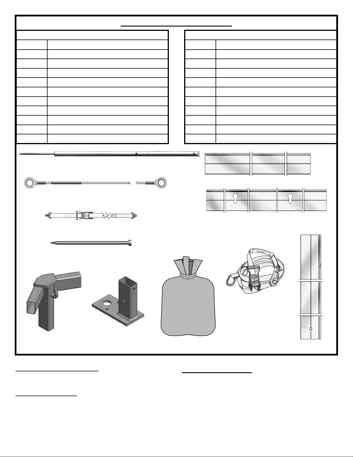
Parts Lists & Illustrations
20’ Hex Parts Table
Quantity Description
1 Center Pole
3 Cables
6 Tension Straps
6 10’ Eaves
6 Uprights
6 Base Plates
6 Guy Webs
1 Bag with Top
6 Corner Weldments
6 Walls (10’ - 2 pc. -- optional)
Center Pole
Cable
30’ Hex Parts Table
Quantity Description
1 Center Pole
3 Cables
6 Tension Straps
6 15’ Eaves
6 Uprights
6 Base Plates
6 Guy Webs
1 Bag with Top
6 Corner Weldments
6 Walls (15’ - 2 pc. -- optional)
10’ Eave
Tension Strap
Stake
Corner Weldment
Base Plate
Manpower Required
Three experienced installers should be able to assemble a
tent in less than forty-fi ve minutes.
Tools Required
Sledge Hammer
4’ Step Ladder
(2) 9/16” Wrenches
(2) Fiesta Frame Lifts; optional but recommended.
15’ Eave
Guy Web
Bag with Top
Layout & Check
Utilize the parts list for a quick I.D. and a check list to
ensure that you have all the parts.
Upright
2
Page 3
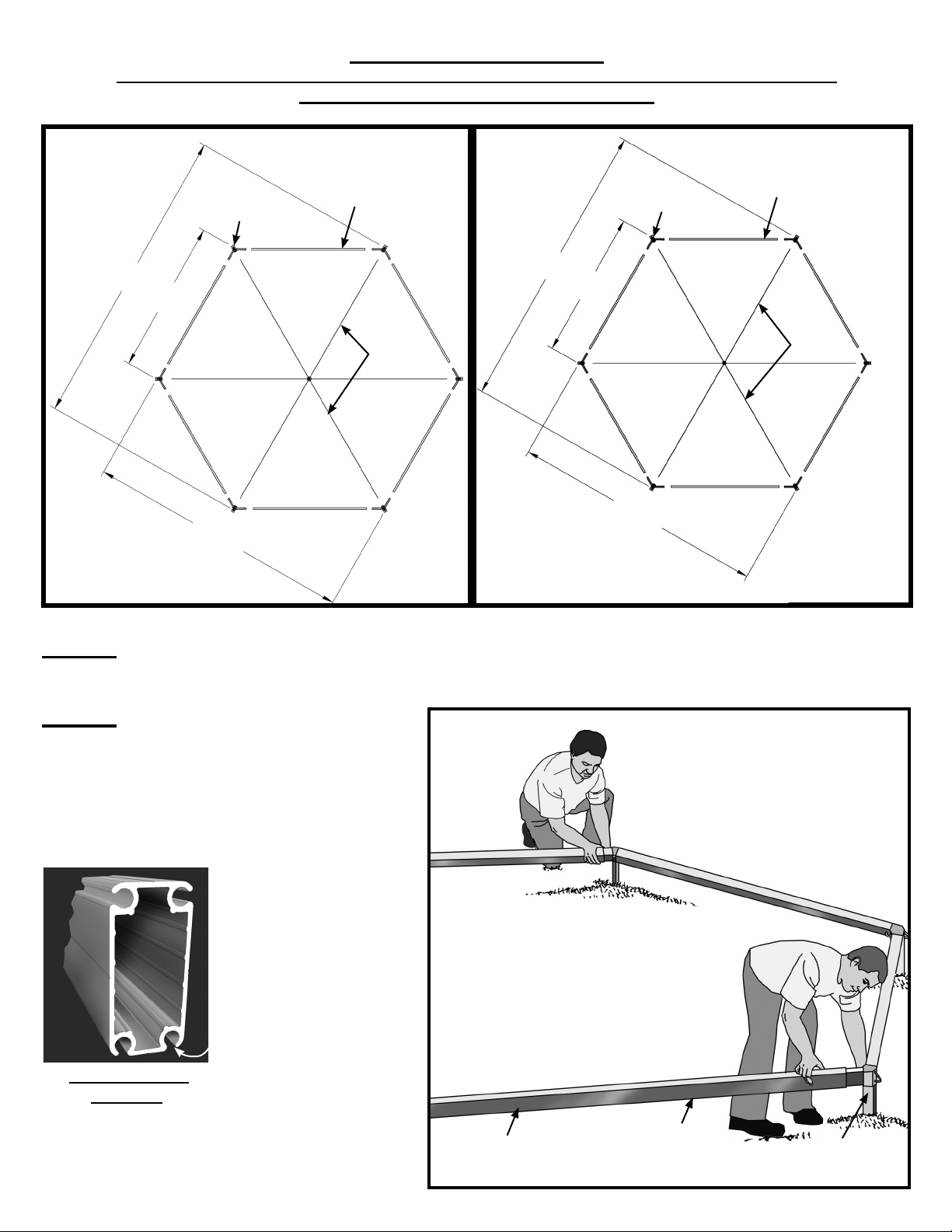
Caution! Inspect Site
Consult local Utility Company prior to installation. Prior to assembly be sure to look
around area for obstacles, pipes, wires, etc.
Corner
Weldment
20’
10’
Approximately
Approximately
Approximately
17’
20’ Hexagon Lay Out 30’ Hexagon Lay Out
10’ Eave
30’
15’
Approximately
Approximately
Cable
Approximately
Corner
Weldment
25’
15’ Eave
Cable
Step 1
Lay out parts for assembly as shown in the diagrams above.
Step 2
Join ends of eaves to corner weldments.
Wall Hangs in Bottom
Outside Channel.
Century Frame
Extrusion
Figure 2
Eave
Wall Channel on
Bottom outside of
beam.
Corner
Weldment
3
Page 4

Step 3 Attach Cables
Attach one eye end of cable to weldment
hook on a corner weldment. At the opposite corner, raise frame until cable loop
slips onto weldment hook, then lower to
ground. Repeat until all 3 cables are attached to frame.
Weldment hook.
Cable eye end.
Step 4 Put Top on Frame
Unfold top over eaves and cables. Pull
tabs at corners of top over corner weldments. Secure by placing slot in tabs
over ring on corner weldment.
Cable
Figure 3
Ring on Corner
Weldment
After tab is in place, fasten guy web snap to ring on
corner weldments. Attach base plates to uprights with
bolt and nut supplied.
Slot in
Ta b
Snap guy to ring
after tab is in place.
Step 5 Lift one Side
For 20’ hex frame: No frame lifts are required. Lift one
corner of frame and fi t upright onto weldment. As up-
rights are inserted, attach tension straps to keep uprights
attached to weldments. (See Step 6) Repeat at second
upright at an adjacent corner. Now stop to raise peak
(See Step 7)
Upright
20’ Hex Frame
Figure 4
Wind
Note: If wind is strong, drive in stakes through the guy
web ring and tie off loosely before lifting frame. (Reference step 10)
4
Figure 5a
Page 5

Step 5 (cont’d)
For 30’ hex frame: Two frame lifts
are required. Position the two lifts
on one eave as shown and attach
hooks to eave tube. Crank both
lifts at the same time. Stop when
uprights will fi t onto weldments.
Lower and remove frame lifts.
Note: If wind is strong, drive in
stakes through the guy web ring
and tie off loosely before lifting
frame. (Reference step 10)
Upright
30’ Hex Frame
Wind
Step 6 Attach Tension Straps
Place curtain web through triangle ring at end of corner tab
as shown in Figure 6. Fasten upper hook of tension strap to
curtain web. Insert lower hook into slot in upright.
Use ratchet to take up slack in web. This prevents uprights
from sliding off weldment when other side of tent is raised.
Do not tension at this time.
Repeat at other uprights in similar fashion.
Step 7 Adjust Center Pole
Center pole must be adjusted to the height shown in Figure 7a. Turn the
top of the center pole in the direction noted to meet the required dimension.
Frame Lifts
Ratchet
Figure 5b
Curtain Web
Tension Strap
Upright
Slot in Upright
Figure 6
Carefully position center pole pin through pole hole in top. Use caution
to prevent tearing of fabric. Raise top by pushing pole on the upper
cable. Slide pole along cable until at intersection of all cables. Place
lower cable in slot at bottom of pole and attach lock pin to secure. See
Figures 7b and 7c.
Caution:
Base of pole is on a roller for ease of installation. Be sure movement of
pole is controlled (fi rmly held) during installation and removal to prevent
base from moving too quickly.
Shorten Lengthen
20’ Hex
7’-4”
30’ Hex
12’-9”
Figure 7a
5
Page 6

Center Pole
Cables
Pole Pin
Center Pole
Lock Pin
Roller
Figure 7b
Step 8 Lift Other Side
Raise opposite side by repeating Step 5. Attach remaining uprights.
Plumb uprights.
Step 9 Installing Optional Walls
Determine proper mating of 2-piece walls with labels
on the inside. Slide tabs at top of walls into bottom
outside channel opening (see Century Frame extrusion drawing on Page 3).
Orient walls so that beading edges are adjacent to
uprights and the lace edges meet in the middle.
Figure 7c
Figure 9
Step 10 Attach Walls to Uprights
At each upright gather up wall and insert bottom of beading into
channel opening at top of upright. Feed all of beading into channel.
6
Figure 10
Page 7

Step 11 Secure Tent
Make certain that tent is positioned in the desired location. Drive
a 1” x 30” stake through each base plate.
Drive a 1” x 30” stake through the ring at bottom of web guy. See
Figure 9 for positioning of stake.
Tension web guy.
Proceed around tent until all web guys are tensioned. See guy
web operating instructions provided.
IMPORTANT NOTE: PLEASE REFER TO CAUTION AND
OTHER ANCHORING INFORMATION ON BACK PAGE.
Step 12 Tension Top
A firmly tensioned top is required for proper installation.
Pull fabric tightly and smoothly to minimize water pooling, wind damage, fabric shifting. Use ratchets on tension straps to tension the top (See Step 6).
Now tighten all eight of the fiesta straps spaced between
the uprights (See Step 10).
Step 13 Take Down
1. Remove guy webs and stakes.
2. Loosen tension straps.
3. Reverse installation steps.
IMPORTANT:
Check web guys and tension straps periodically for tight-
ness and good condition.
Store tent in a cool, dry area. Never store while wet or
damp.
Figure 9
Note:
The center of the fabric eaves should be
approximately 3” below the frame eaves
when properly tensioned.
3” Approximately
20’ Hex - 6’-8 Minimum
30’ Hex - 11’-5 Minimum
Eave Line
Note:
Tensioning of top can change from installation to installation. Cable stretch, fabric shrinkage or elongation and other
factors can require a different amount of tension to center pole.
7
Page 8

EVANSVILLE, INDIANA
PHONE NUMBER
812· 867· 2421
FAX NUMBER
812· 867· 0547
Anchor products are of superior design and operate best within the parameters of these instructions. It is imperative
that the instructions be carefully read and COMPLETELY FOLLOWED. Please read installation instructions before the
installation or removal of this product. Installation instructions are available online at www.anchorinc.com or by calling
1-800-544-4445.
CAUTION:
1. For each installation, the installer is solely responsible for evaluating the site and the proper securing method
determined. Some soils require different staking or securing than that provided with the tent. Due to this variety of
soil conditions, these are the manufacturer’s suggested sequence of installation procedures. Anchor’s responsibility
is limited to the manufacture of the tent parts and materials. We are not responsible for methods that installers may
choose to erect and secure the tent to the ground.
2. The number of stakes suggested in the installation instructions does not necessarily meet all or any relevant codes
on the site of the tent installation. The number of stakes suggested will, in many cases, keep the tent erected,
however, due to various soil conditions; these stakes will be insuf¿ cient to keep the tent secure in high winds.
It is the tent installer’s responsibility, not the manufacturer, to determine the appropriate number of stakes to meet
the necessary wind loads on the site. Regardless of the number of stakes we suggest, we make no representation
or warranty as to whether this speci¿ c number of stakes will meet the local tent code. Anchor does not, nor can
it make any suggestions, representation, or warranties about the adequate staking required at each speci¿ c
installation site. Staking information provided in the installation instructions is not a suggestion about what is
necessary to meet a site-speci¿ c load.
For additional assistance, consult: “The IFAI Procedural Handbook For the Safe Installation and
Maintenance of Tentage” and the IFAI Pocket Guide “Pullout Capacity of Tent Stakes”, both available from
the IFAI Tent Rental Division or on our website.
3. Inasmuch as the weather is unpredictable, good judgment and common sense must be incorporated within
installation guidelines. It is the responsibility of the tent installer/maintainer to determine the severity of the weather,
proper time and method of installation and/or erection and disassembly. Note: We recommend that snow and
ice be removed from the tent surface as soon as possible because accumulation will damage the tent
or fabric structure. Please consult with our Engineering Department about the maximum loads for each
product.
This product has been manufactured for use as a temporary structure. For the safety of all occupants, evacuation
is recommended if threatening weather occurs, or if there is any doubt concerning the safe use of this product.
4. Proper safety equipment should be used at all times to insure a safe installation and take down. We suggest a
careful evaluation be made to determine safety equipment needed, such as hard hats, steel-toe shoes, safety
glasses and other as required. It is our desire that all installations are safe. Please be aware of hidden dangers
both underground, i.e., gas lines, water lines, electrical lines, etc. and above the tent such as power lines and
telephone lines.
5. Anchor stands behind its products in accordance with its standard Terms and Conditions of sale. A copy of our
Terms and Conditions of Sale can be obtained by contacting Anchor at the telephone number and/or address on
this document.
28.2 04-29-08
 Loading...