

Page 1
ASSEMBLY INSTRUCTIONS
EVANSVILLE, INDIANA
SALES OFFICES:
1100 Burch Drive
P.O. BOX
Evansville, IN 47733-3477
Phone: 800-544-4445
Fax: 812-867-0547
E-mail: tents@anchorinc.com
Website: www.anchorinc.com
FMSS-0604
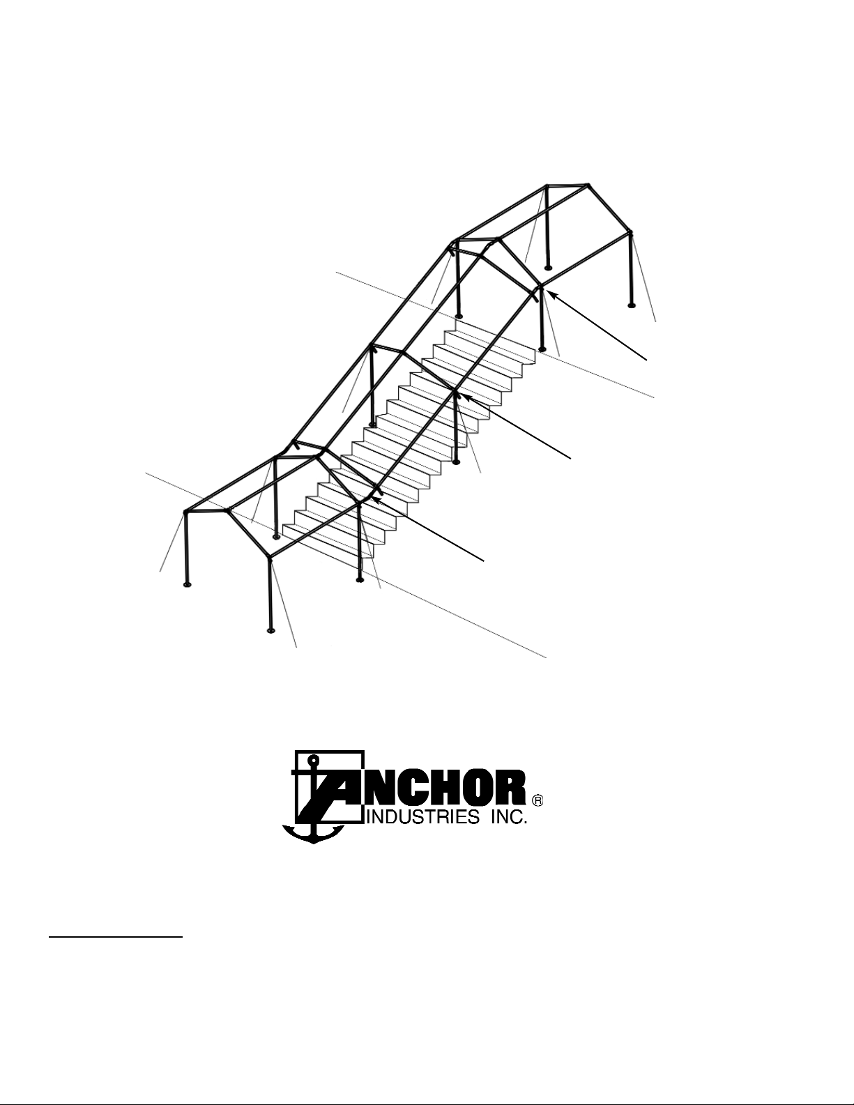
STAIR STEP KIT FOR FIESTA MARQUEE
Quality, Craftsmanship and Service since 1892
UPPER LEVEL
LOWER LEVEL
ASCENDING ANGLE
INCLINED SECTION
DESCENDING ANGLE
Page 2
Inst
alling the St
air Step Kit into standard Fiesta Marquee framing:
FOR SAFETY, EASE AND STABILITY, WE RECOMMEND BUILDING THE FRAME COMPLETE BEFORE INSTALLING THE LEGS.
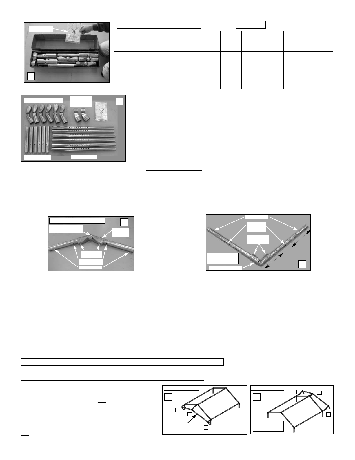
Constructing the Upper Level with Descending Angles (see Fig.6):
Build from eaveto-peak-to-eave
1
3
2
Descending Angle
Build from eaveto-peak-to-eave
1
3
2
Ascending
Angle
5. Position two units of standard Fiesta Marquee framing
(one at the top and one at the bottom of the incline).
6. Starting at either eave of the top
unit (Fig.6), pull
the pin holding the eave bar to the Eave Casting and
insert the splice of a Short Adapter Assembly into both
the casting and
eave tubing of the Marquee. Rotate the
splice hole into alignment (45 degrees to the outside of
vertical), and replace the pin.
Standard Marquee
Rafters (2)
6
7
Short Inserts
Long Inserts
Adjustable Elbows
Upright
Adapters
Instructions
Boxed Stair Step Adapter Kit #8090502
Parts Laid Out by Component Type
Adapter Assemblies:
Short Adapter Assembly
Short Insert (2)
Adjustable
Elbow (1)
Use 5/16”
Allen Wrench
Alignment Hole
Alignment
Holes
Adjustable Elbow (1)
Long Insert (2)
Use 5/16”
Allen Wrench
Long Adapter
Assembly
Long
Short
1. Assemble (1) Short Insert into each end of (3) Adjustable Elbows (fig.4). The alignment hole is closest to the end of the Short
Insert that connects to the Adjustable Elbow. Partially tighten the set screws, using a 5/16” Allen Wrench.
2. Assemble (1) Long Insert into each end of the (3) remaining Adjustable Elbows (fig.5). Partially tighten set screws, using a 5/16”
Allen Wrench. The alignment hole pattern is closest to the end of the Long Insert that connects with the Adjustable Elbow.
At this time, the standard Fiesta Marquee frames for the upper and lower levels can be built and positioned. However, the adapter
kit will be easier to install if the uprights (legs) are left off the sections that will join with the Descending and Ascending Angled
frames until after the adapter kit has been installed on those standard frames components.
1
3
4
5
Rotation Screw. Use
1/4” Allen Wrench
Contents of Stair Step Kit:
You should now have (3) Short Adapter Assemblies (see Fig.4) and (3) Long Adapter Assemblies (see Fig.5); The (2) Upright
Adapter Assemblies are shipped pre-assembled and will be used later (see fig.9)
NOTE: Only the parts listed in Table 2 are included in this kit. These kit parts are pic-
tured in fig 1 and 3. All other frame parts illustrated in these instructions are stan-
dard Fiesta Marquee components and are not a part of this Stair Step Adaptor Kit.
IT IS ASSUMED THAT THE CUSTOMER ALREADY HAS, OR IS PURCHASING, THE BASIC
FIESTA MARQUEE FRAMES THEMSELVES.
T
OOLS REQUIRED: (1) 5/16” Allen Wrench, (1) 1/4” Allen Wrench - - (Tools Not Provided)
Component
Description
Inventory
No.
Figure
No.
First (2) Bays
Kit #8090502
(Qty of Parts)
Additional Bays
Kit #8090691
(Qty of Parts)
Short Insert 8090505C 3 6
Long Insert 8090506C 3 6
Adjustable Elbow 8090507C 3 6
Upright Adapter Assemblies 8090508C 3 & 9 2 2
2
4. Notice that at the Descending Angle of the Marquee (see front cover) there are (2) Short Adapter Assemblies at the Eave (each
side) and (1) Long Adapter at the ridge. At the Ascending Angle of the Marquee, this pattern is reversed. There, there are (2)
Long Adapter Assemblies at the eave (each side) and (1) Short Adapter Assembly at the ridge. At the Inclined Sections, there
are (2) or more Upright Adapter Assemblies (1 per Upright), depending upon the overall length of the incline or stairs.
Table 2
To prepare the Stair Step Kit for installation, assemble the (3) Short and (3) Long
Adapter Assemblies, as shown (fig.4 & 5). In doing this, please note the following
guidelines. Please read all steps before proceeding:
3. Note: The alignment hole rotation depends upon the location of the part in the Fiesta Marquee frame. The adapters located at the
ridge line of the Marquee will have the alignment holes facing upward in a 90 degree vertical direction. Those adapters located at
the eave line will have the alignment hole rotated 45 degrees to the outside of vertical (left or right, depending upon which side of
the Marquee the part will be. In uneven terrain, it is better to wait until the moment of installation to tighten the alignment holes.
DISTRIBUTION OF
ASSEMBLIES THROUGH THE FRAME:
Page 3

INST
ALLING FABRIC
GUYING OFF THE FRAME
15. Prior to installing the upright legs under the frame, stakes should be driven and guy ropes attached. Consult the standard
Fiesta Marquee Installation Instructions for correct stake location and guying pattern.
CAUTION: Be sure the frame is guyed and stabilized before installing the fabric.
16. Consult the standard Fiesta Marquee Installation Instructions for fabric installation instructions. The fabric sections for the
ascending and descending angled sections will install in a similar fashiong and velcro to the standard fabric top sections.
RAISING THE FRAME
Raising the Top Level (See Fig.10)
CAUTION: A. Adjust guy rope tension selectively to protect against the wind until each section is raised and safely guyed.
B. Be sure to allow enough time and crew size to complete and secure the entire
unit.
C. Alway raise the “downwind” sides first to prevent the wind from getting under the unit and lifting it beyond control.
D. Before raising the frame, go back and pin all Long Adapter Assemblies to lock in the adjustability of the splices.
17. At the Long Adapter Assembly (in the ridge), choose the most nearly aligned hole of the Long Insert
and replace the pin to lock out further adjustment of the splice insertion and secure the connection.
18. Raise the Top Level first. Insert legs under the “downwind” side, and then the “upwind” side,
selectively loosening and tightening guy ropes throughout the whole frame, as needed for wind.
19. Properly align the legs and re-tighten the guy ropes according to standard Fiesta Marquee Installation
Instructions.
Raising the Lower Level (See Fig.11)
20. At the Long Adapter Assemblies (in the eave), choose the closest hole of the Long Insert and replace
the pin to lock out further adjustment of the splice insertion and secure the connection.
21. Raise the Lower Level next, again inserting legs under “downwind” side and then the “upwind” side.
22. To raise this Top level, selectively loosen guy ropes, as needed. Safely tighten guy ropes.
Raising the Inclined Section (See Fig.12)
23. To finish the installation, finish pushing the intermediate uprights (legs) to vertical and secure. Loosen
and re-tighten guy ropes, as needed.
24. Using a 1/4” Allen Wrench, tighten the rotation screw (See fig.4) in each Adjustable Elbow (in all
sections of the frame) to secure the hinges at the correct angle for the slope of the stairway or incline.
CAUTION: Before leaving the site, be sure all fabric is properly secured and all guy ropes
are uniformly tensioned according to the standard instructions for the Fiesta Marquee.
10
12
Adjustable
Inserts
Adapter Splices aligned for
up and down vertical swings.
Constructing the Lower Level with the Ascending Angle (See Fig.7):
Ridge
Pin.
Eave
Pin.
7. AT the Ridge Casting, pull the pin and install a Long Adaptor Assembly with holes aligned at a 90
degree angle. Leave the pin out at this connection until the overall inclined frame is completed.
This will allow easy adjustment to the angle of the incline.
8. At the opposite eave, repeat steps 1 and 2 above. Be sure to pin this eave adapter
.
9 . Check to see that all (3) adapter assemblies rotate freely in a vertical direction and tighten the
splices into the Adjustable Elbows, using a 5/16” Allen Wrench (see Fig.9).
10. Insert and pin standard Fiesta Marquee rafters from eave to peak to eave to complete the angle.
Constructing the Inclined Section of Framing
12. Insert Eave and Ridge bars into the available locations of the Descending
Angle and pin.
13. Insert the opposite ends of these same Eave and Ridge Bars into standard
PTI castings and construct the rafter for the inclined section. Slide Upright
Adapter Assemblies onto the PTI splice and pin uprights to these assem
blies (See the inset in Fig.9). Let the uprights hinge forward down the
incline until later when the frame will be raised.
14. Install another set of standard Eave and Ridge Bars between the incline
uprights and the Lower Level (see fig. 1) on page 1. If necessary, adjust
the Long Adapter Assembly splices at the eaves of the Lower Level.
8
9
3
EAVE BAR
EAVE BAR
PTI
CASTING
PTI SPLICE
Slip the Upright Adapter Assembly up over the
PTI Splice, adjust to appropriate level & tighten.
11. For the Lower Level and the Ascending Angle, repeat Steps 1 through 7 above in reverse, using (2) Long Adapter Assemblies at
the eaves and (1) Short Adapter Assembly at the ridge. Pin the Short Adapter Assemblies, but Leave Long Adapter
Assemblies unpinned for easy adjusment to the proper angle when the inclined frame is being assembled (below).
NOTE: If the stairway is long enough to require additional units, you will need (1) additional Kit #8090691for each pair of uprights.
11
Page 4

28.2 11-01-02
Thank you for purchasing an Anchor product. In return, we pledge Quality, Service and
Craftsmanship and are available for any questions you may have or assistance you may need.
PHONE NUMBER
812-867-2421
FAX NUMBER
812-867-0547
Anchor products are of superior design and operate best within the parameters of these
instructions. It is IMPERATIVE that the instructions be carefully read and COMPLETELY
FOLLOWED. Please read installation instructions before the installation or removal of this
product. Installation instructions are also available at: www.anchorinc.com.
CAUTION
1. For each installation, the installer is solely responsible for evaluation of the site and the proper
securing method determined. Some soils require different staking or securing than that provided
with the tent. Due to this variety of soil conditions, these are the manufacturer’s suggested
sequence of installation procedures. Anchor's responsibility is limited to the construction of the
tent. We are not responsible for methods that installers may choose to secure the tent to the
ground.
2. Inasmuch as the weather is unpredictable, good judgment and common sense must be
incorporated within installation guidelines. It is the responsibility of the tent installer/maintainer to
determine the severity of the weather, proper time and method of installation and /or erection
and disassembly. This product has been manufactured for use as a temporary structure. For
the safety of all occupants, evacuation is recommended if threatening weather occurs, or if there
is any doubt concerning the safe use of this product.
3. Proper safety equipment should be used at all times to ensure a safe installation and take
down. We suggest a careful examination be made to determine safety equipment needed, such
as hard hats, steel toe shoes, safety glasses and other as required.
4. Anchor stands behind its products in accordance with its standard Terms and Conditions of
sale. A copy of our Terms and Conditions of Sale can be obtained by contacting Anchor at the
telephone number, address on this document.
EVANSVILLE, INDIANA USA
4
 Loading...