

Page 1
EVANSVILLE, INDIANA
SALES OFFICES:
1100 Burch Drive
P.O. Box 47733
Evansville, IN 47733-3477
Phone: 800 544-4445
Fax: 812-867-0547
E-mail: tents@anchorinc.com
Website: www.anchorinc.com
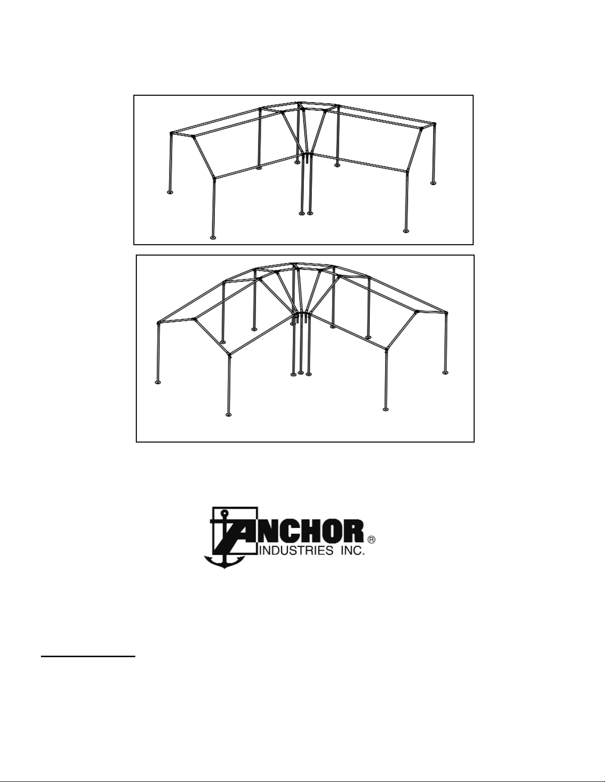
Frame Kit in 45 Degree Turn
Frame Kit in 90 Degree Turn
Round Corner Kits for Fiesta Marquee Frames
INSTALLATION INSTRUCTIONS
Quality, Craftsmanship and Service since 1892
FMRC-0404
Page 2
FRAME QUANTITIES PER KIT
COMPONENT DESCRIPTION
DWG
LTR
INVENTORY #
45 Degree Turn
Kit # 8085033
90 Degree Turn
Kit # 8085031
PTE CASTING (CUSTOM)
A
8085034
6 6
DOUBLE PTE WELDED CASTING
B
8085035
3 9
EAVE BAR
C
varies with size
2 4
EAVE/ RIDGE BAR
D
varies with size
2 4
3/8”-16 x 1 1/2” Hex Hd Cap Screw, Grd 5, zinc 3023220
10 20
3/8”-16 Hex Nut, zinc 3024340
10 20
3/8” Lock Washer, zinc 3025330
10 20
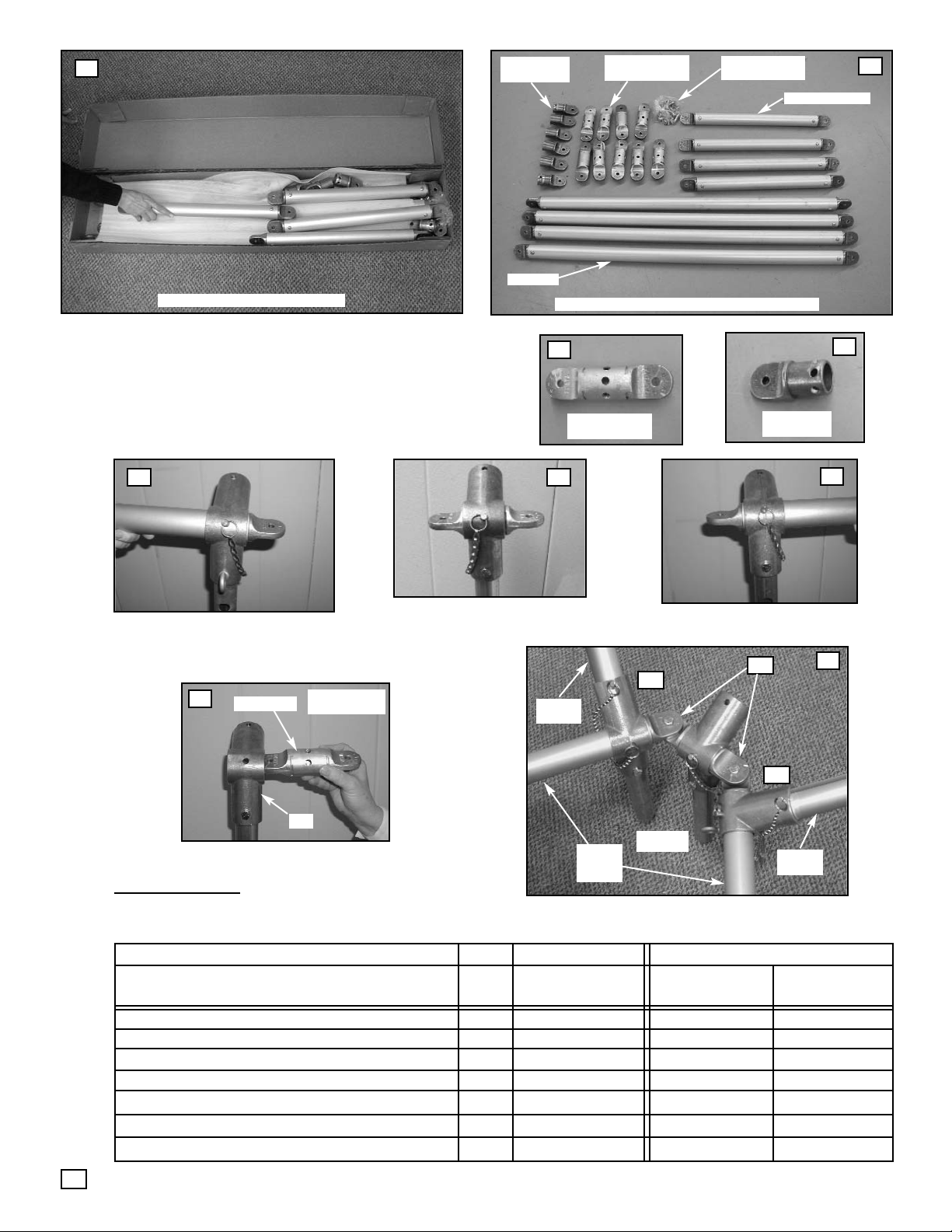
90 Degree Kit (#8085031) Boxed.
90 Degree Kit (#8085031) Parts Laid Out
Eave Bars
Eave/ Ridge Bars
PTE Castings
(Custom)
Double PTE
Welded Castings
3/8”-16 Bolt, Nut
& Washer Sets
PTE Casting
(Custom)
Double PTE
Welded Casting
The Round Corner Kits are simply adapter kits that allow standard
Fiesta Marquee frames to turn corners of 45 or 90 degrees.
The Kits include only the unique parts needed to make these corner turns. The kit assumes the customer either owns or is purchas-
ing all the necessary standard Fiesta Marquee frame parts, including
the standard Rafters, Uprights, PTI and PTR Castings used in the corner turn itself, which are not included in the kits.
Installing the Double PTE
1
2
3
4
5
6
7
9
8
SECURE WITH
SMALL PIN
Custom PTE installed and pinned into a
PTI at the left side of the inside radius
Custom PTE installed and pinned into a
PTI at the right side of the inside radius
Inside Radius with eyes overlapped and bolted
together to form the angled turn of the eave frame
Double PTE Welded Casting,
installed and pinned into a PTI
Eaves of
Standard
Marquee
A
A
B
(3) PTI’s
Standard
Rafter
Standard
Rafter
2
PTI
DBL-PTE
T
OOLS REQUIRED
:
(Not Provided) Ratchet Wrench w/ 9/16” Socket
Page 3

Please notice in the above overhead view of the 45 and 90 degree Fiesta Marquee Round Corner Kits that only the parts lettered
and identified here are actually included in this kit. All other parts, including all the rafters, eave bars, ridge bars, PTI’s, PTR’s and
uprights are assumed to be pre-owned or being purchased separately by the customer. Those standard Fiesta Marquee parts
are not included in this kit. (See Fig.2 for a layout of the parts that are included in the kits.)
10
11
45 Degree Kit #8085033 parts lettered A,B,C,D.
(Dotted lines are standard parts not in the kit)
90 Degree Kit #8085031 parts lettered A,B,C,D.
(Dotted lines are standard parts not in the kit)
Overhead View
Overhead View
A-B-A
D
D
C
C
A
A
B
A-BBB-A
C
C
C
C
D
D
D
D
A
A
A
A
B
B
B
B
B
B
A
A
B
Ridge Bar
Ridge Bar
Eave Bar
Eave Bar
Eave Bar
Eave Bar
OUTSIDE RADIUS
INSIDE RADIUS
OUTSIDE RADIUS
INSIDE RADIUS
Ridge Bar
Eave Bar
Eave Bar
Ridge Bar
Eave Bar
Eave Bar
All Standard Rafters (10)
All Standard Rafters (14)
1. Refer to the standard Fiesta Marquee Frame installation instructions and assemble (2) standard Fiesta Marquee units ( 9’ x 10’
frame unit). These units should be built without legs and be supported by the upright splices at the bottom of the PTI
castings at the four corners of each unit. Align (1) unit as required for your installation site. Position the other near the opposite
end of the intended radius (Fig 10 & 11).
2. Construct the inside radius using additional PTI’s with PTE Custom Castings “A” and Double PTE Welded Castings “B” as follows:
a. On the standard eave that will lead into the turn, pull the pin that secures the eave bar to the PTI, insert a PTE Custom
Casting into the PTI and the end of the eave bar, with the eye end facing the desired radius turn. On the shaft of the PTE
Custom Casting choose the pin hole that will position the eye tab horizontal to the ground and replace the pin to re-secure
the connection (Fig.5). Repeat this process for the other standard unit (Fig.7).
b. Into a second PTI, insert a Double PTE Welded Casting (see Fig.8), aligning the holes so that the eye ends will be hori-
zontal with the ground, and pin with the small PTI pin. If you are constructing a 45 degree turn, (1) PTI with the Double PTE
will be enough. If you are constructing the 90 degree turn, you will need to assemble (3) of these (Fig10 & 11).
c. Overlap the eye fittings of the inside radius casting and bolt together, using the 3/8” -16 x 1 1/2” Hex Hd Cap Screws with Nut
and washer (Fig.9).
3. Into the center PTI, Install a standard Fiesta Marquee rafter and pin it. The end PTI’s of the standard units should already have
rafters installed, from Step #1, above.
4. At the upper end of the rafter installed in Step #3, install a standard PTR (see standard Fiesta Marquee Instructions). Into this
PTR, install a Double PTE Welded Casting in the same way as it was installed into the PTI (Fig.8). Choose the Pin hole that
will result in the eye fittings being horizontal to the ground.
5. Into the PTR’s of the ridge at ends of each standard Marquee unit, remove the small pin, install PTE Custom Castings and replace
the pin, with the eyes horizontal to the ground.
6. Using (2) Eave/Ridge Bars “D”, connect the Double PTE in the ridge PTR of the radius rafters to the PTE Custom Castings in the
PTR’s of each standard Marquee unit. For 45 degree angles, adjust the position of the standard units as necessary to overlap
the PTE’s and bolt with a 3/8” -16 x 1 1/2” Hex Hd Cap Screw with Nut and Washer. If you are installing a 90 degree turn, repeat
steps 3 through 5 on (2) additional radius rafter assemblies, interconnecting each rafter with Eave/Ridge Bars “D”.
7. On the opposite side of the ridge, install additional standard rafters extending toward the outside radius of the angled framing.
8. On the opposite eave, construct the outside radius in the same manner as the inside radius (See step # 2, above), but develop
the needed spacing by installing an Eave Bar “C” between the eyes of the Custom PTE’s “A” of the standard units and the Double
PTE’s “B” of the radius rafter assemblies, and also between the Double PTE’s themselves of the radius rafter assemblies.
9. Install guy ropes to the eave fittings of the entire frame, but leave them slack, so as not to impede the later lifting of the frame.
10. Refer to the standard Fiesta Marquee Instructions and install the fabric tops to all units described above.
11. Lift the frames and insert legs under all PTI’s along the eave line of the standard units and the middle
PTI of the radius sections.
12. Refer to the standard Fiesta Marquee Instructions and tighten all guy ropes to secure the unit.
INST
ALLATION SEQUENCE AND GUIDELINES:
3
Page 4

28.2 11-01-02
Thank you for purchasing an Anchor product. In return, we pledge Quality, Service and
Craftsmanship and are available for any questions you may have or assistance you may need.
PHONE NUMBER
812-867-2421
FAX NUMBER
812-867-0547
Anchor products are of superior design and operate best within the parameters of these
instructions. It is IMPERATIVE that the instructions be carefully read and COMPLETELY
FOLLOWED. Please read installation instructions before the installation or removal of this
product. Installation instructions are also available at: www.anchorinc.com.
CAUTION
1. For each installation, the installer is solely responsible for evaluation of the site and the proper
securing method determined. Some soils require different staking or securing than that provided
with the tent. Due to this variety of soil conditions, these are the manufacturer’s suggested
sequence of installation procedures. Anchor's responsibility is limited to the construction of the
tent. We are not responsible for methods that installers may choose to secure the tent to the
ground.
2. Inasmuch as the weather is unpredictable, good judgment and common sense must be
incorporated within installation guidelines. It is the responsibility of the tent installer/maintainer to
determine the severity of the weather, proper time and method of installation and /or erection
and disassembly. This product has been manufactured for use as a temporary structure. For
the safety of all occupants, evacuation is recommended if threatening weather occurs, or if there
is any doubt concerning the safe use of this product.
3. Proper safety equipment should be used at all times to ensure a safe installation and take
down. We suggest a careful examination be made to determine safety equipment needed, such
as hard hats, steel toe shoes, safety glasses and other as required.
4. Anchor stands behind its products in accordance with its standard Terms and Conditions of
sale. Acopy of our Terms and Conditions of Sale can be obtained by contacting Anchor at the
telephone number, address on this document.
EVANSVILLE, INDIANA USA
 Loading...