

Page 1
ASSEMBLY INSTRUCTIONS
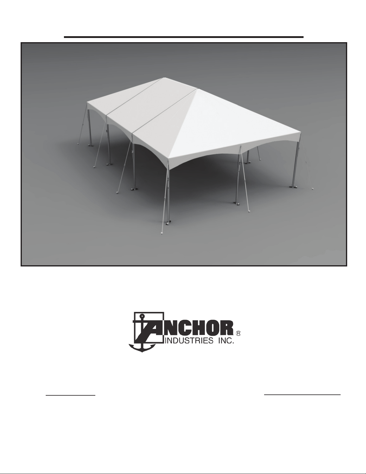
F3 FRAME TENT
SALES OFFICES:
1100 BURCH DRIVE
PO BOX 3477
EVANSVILLE, IN 47733 USA
PHONE: 812-867-2421
FAX: 812-867-0547
1-800-544-4445
EMAIL: tents@anchorinc.com
www.anchorinc.com
20 x 30’ Shown
PRODUCTION FACILITIES:
EVANSVILLE, IN
EC4762
Quality, Craftsmanship and Service since 1892
F3 7-9-14
Page 2

Table of Contents
PAGE NO. DESCRIPTION
3 General Notes, Safety Notes
4 Frame terminology, Clearance Dimensions
5 Component list, illustrations
6 Layout and Begin connections
7 Installation cross web for 30’ frame
8 Completion of top frame members
9 Installation of hip and mid fabric
10 Frame Lifts, Tensioning
11 Tensioning order, Stakes and guys
2
Page 3

General Notes:
• The installation manual describes in a methodical manner the assembly and erection of the Anchor frame tent. Please
read all instructions before the installation or removal of this product.
• Installer must determine the number of persons and the proper equipment required for each installation.
• Work from step to step.
• Before erecting any tents or membrane structures, fi rst obtain permits and approvals as required from the local building
and fi re code offi cials on the jurisdiction of your installation.
PLEASE PAY SPECIAL ATTENTION TO SAFETY WARNINGS AND CAUTIONS FOR PREVENTION
OF ACCIDENTS.
Regarding the contents of the installation manual:
The illustrations and photos are made to show clearly the construction and dismantling procedures and also for identifi cation
of the components. Not all illustrations/photos correspond to the actual dimensions and size. Explanations and/or notes have
been added to these illustrations/photos.
If you have questions, please call your sales representative at the phone number listed on the front or back of the manual.
Safety Notes:
• Please read through the installation manual completely before beginning your installation. Be sure the proper equipment
and safety precautions are in place.
• Consult your local utility locator service or the National Utility Locating Contractors Association (NULCA) prior to
installation.
• Prior to actual tent assembly, be sure to look up, down, above & below for obstacles, pipes, wires, trouble, etc.
• Be alert to avoid contact of frame sections with any overhead power lines near the site.
• Keep site clear of debris to avoid tripping, especially while carrying frame parts or bundles of fabric.
• When moving frame sections by hand, use proper lifting techniques to protect the back, and avoid pinching fi ngers while
making hardware connections.
• The installation method described in the installation manual requires coordination of tasks between workers. A safe instal-
lation is dependent on that coordination. Work cooperatively as a team.
• Be sure all pins and bolts are installed and secured correctly during assembly.
• Ensure that all push buttons are fully engaged at all frame/weldment connections.
• Replace damaged or worn components with original Anchor components. Failure to use original Anchor components may
void product warranties.
• To prevent injuries, wear suitable protective clothing such as hard hats, steel toed shoes, etc.
• Do not drag bundle of fabric on concrete, asphalt, or ground as this can cause damage to the fabric from abrasion through
the bag.
• Installation supervisors must take responsibility to instruct all installers about possible dangers before installation and
erection begins.
3
Page 4
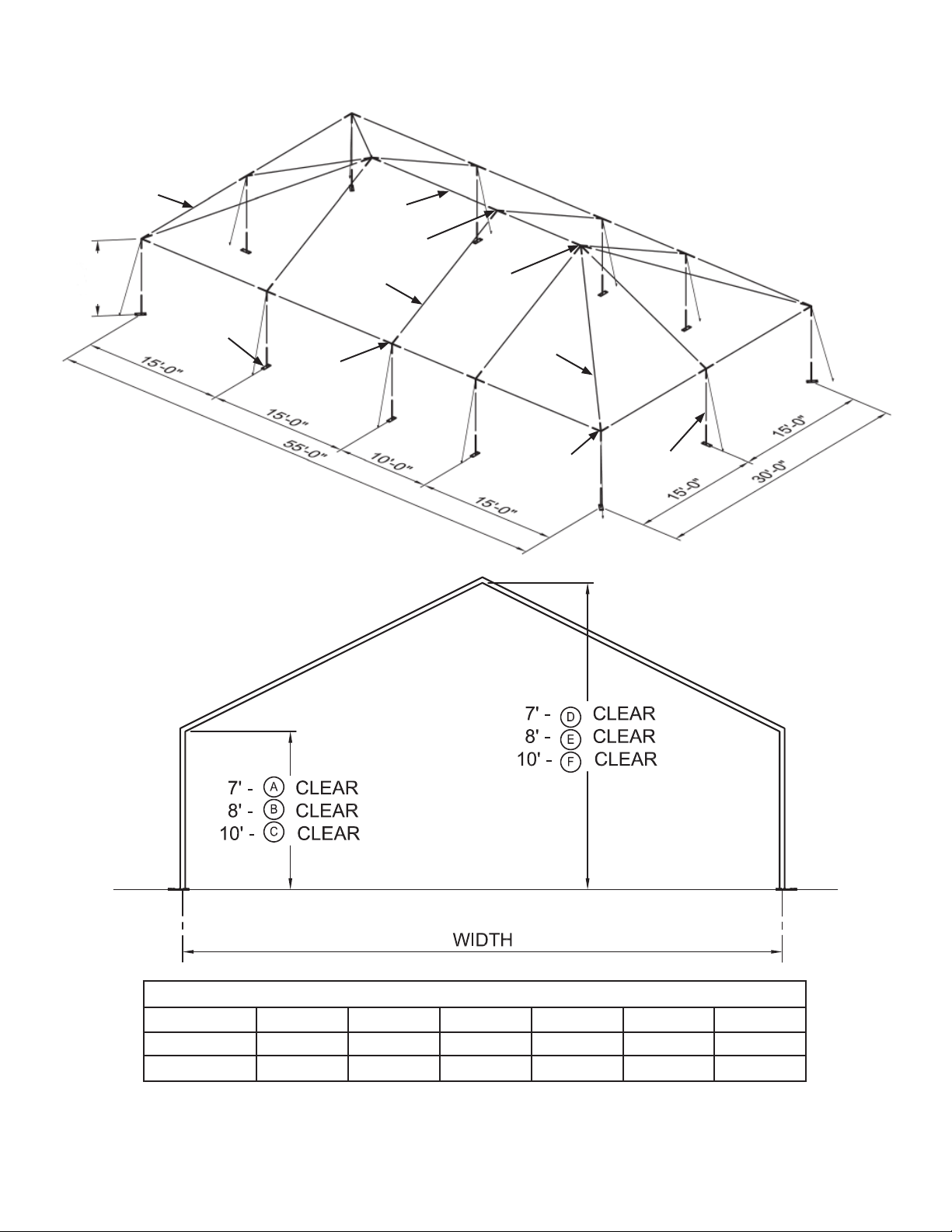
F3 FRAME TERMINOLOGY
EAVE/
RIDGE
PURLIN
7’
8’
10’
BASEPLATE
RAFTER
INT.
EAVE/
RIDGE
PURLIN
RIDGE
INT/INT
RIDGE
HIP/INT
HIP
CORNER
UPRIGHT
CLEAR DIMENSIONS
Frame Width
20’ 7’-0” 8’-0” 10’-0” 11’-8” 12’-8” 14’-8”
30’
4
ABCDEF
7’-0” 8’-0” 10’-0” 14’-2” 15’-2” 17’-2”
Page 5

COMPONENT LIST
Description
QUANTITIES
20’ x 20’ 20’ x 30’ 20’ x 40’ 30’ x 30’ 30’ x 45’ 30’ x 60’
WELDMENTS
Ridge Hip/
Intermediate
Ridge
Intermediate/
Intermediate
Ridge Hip/Hip 1 - - 1 - -
Intermediate 468468
-22-22
--1--1
Corner 444444
Adjustable
Baseplate
7’ - 6’-6 3/8”
Fixed Upright
20’ Rafter 10’-7 7/16” 4 6 8 - - -
30’ Rafter 16’-2 1/2” - - - 4 6 8
20’ Hip 14’-2 1/8” 4 4 4 - - -
FRAME
30’ Hip 21’-8 3/16” - - - 4 4 4
10’ Eave/Ridge Purlin 9’-5 1/2” 8 10 12 - - -
15’ Eave/Ridge Purlin 14’-5 1/2” - - - 8 11 14
Base Plate Pin - 8 10 12 8 10 12
8’ - 7’-6 3/8”
10’ - 9’-6 3/8”
8 10 12 8 10 12
8 10 12 8 10 12
Web Guys - 8 10 12 8 10 12
HARDWARE
5
Page 6

STEP 1 Layout Components for Assembly
Layout components as
shown for your particular size
tent. Square tents will use
the Ridge Hip/Hip Weldment
at Peak.
EAVE/
RIDGE
PURLIN
INT.
RAFTER
HIP
INT.
CORNER
RIDGE
INT/INT
EAVE/
RIDGE
PURLIN
RIDGE
HIP/INT
Frame shown is a 30’ X 60’
Figure 1
STEP 2 Begin connection of components
Begin by attaching rafters to ridge weldment. Align slots in tubes with Stop Buttons on weldment. Push button down
and carefully slide tube onto weldment until button pops up securely into slot. On 30’ Frame you will now attach the
installation cross web. See Figure 2b & 2c.
RIDGE
HIP/INT
HIP
RAFTER
INT.
HIP
EAVE/RIDGE
PURLIN
FRAME LIFTS
CORNER
EAVE/RIDGE
PURLIN
BASE PLATES
AND UPRIGHTS
After all components are connected to ridge weldment, start at one of the Side Intermediate weldments,
connecting rafter to eave weldment, then hip to corner weldment, and on around (see direction on Figure 3)
until the bottoms of all the rafters, hips are connected to weldments.
6
Figure 2a
Page 7

Installation Cross Web
Cross web is installed by running ends
of Cross web around Int. weldment and
thru U-Bolt on outside of weldment.
Attach ring back to hook.
After ends are attached, tension the
strap using the cam buckle.
Installation Cross Web
For 30’ Frame only
Installation Cross Web Installed
on 30’ Frame.
STEP 3 Connect eave purlins to weldments
After rafters and hips are connected to weldments, Start at one of the rafters and
connect eaves to weldments going from one side to the other all the way around.
Figure 2b
Important Dismantling Note: For
Ease in Dismantling (30’ model),
Installation Cross Web must be
reinstalled.
Figure 2c
Installation Cross Web
Installed on 30’ Frame.
END
HERE
START HERE
Figure 3
7
Page 8

STEP 4 Connect next arch
Arch
Installation Cross Web
Installed on 30’ Frame.
Connect rafters to Ridge weldment, then connect Eave/Ridge purlins.
Continue in like manner at next Arch as required.
STEP 5 Connect next arch and other hip end
Continue connections as shown previously until entire frame is
connected and sitting on the weldments.
Figure 4
Figure 5a
8
Page 9

STEP 6 Installation of hip end fabric
STEP 7 Installation of mid fabric
Unroll hip fabric and lay loosely beside frame, right side up.
Connect snap of pull rope to ring at end of kedar. Feed kedar up
into channel a few inches, then pull fabric up and over through
channel in rafter extrusion using the pull rope. One installer
should watch as kedar is fed into channel, while another should
keep hands on fabric as it is pulled over frame to ensure that
fabric does not catch on frame.
When fabric is centered on hip, move on to install the mid or
other end.
Figure 6
Unroll mid fabric and lay loosely
beside frame, right side up.
Connect snap of pull ropes to
rings at ends of kedars. Feed
kedar up into channel, then pull
up and over through channels in
rafter extrusions using the pull
ropes. One installer should watch
as kedar is fed into each channel.
When fabric is centered on frame,
move on to install rest of fabric.
Figure 7
9
Page 10

STEP 8 Raise one side with Frame Lifts
Attach uprights to base plates.
Attach uprights to weldments on one side once
the side is raised to the appropriate height.
When one side has all uprights attached, move
frame lifts to the other side, and raise frame until
the end uprights can be attached.
After these uprights are installed, frame may
need to be lowered slightly so that the final side
can have uprights attached.
Place frame lifts as shown and
attach to eave purlins.
Figure 8
STEP 9 Tension fabric to frame
Tension tent to frame as shown at
right. Run ring of tension strap up thru
both rings of top then back down to
attach to hook on strap. Other end of
strap is hooked into slot provided in
upright.
Go all around the tent and tension all
straps to only snug tightness using
ratchet on strap.
Finish tensioning tent as shown in
figure 9b.
Rafter
Eave Line
Kedar
Upright
Ratchet
10
Figure 9
Page 11

STEP 9 Tension fabric to frame - cont’d
Start tensioning web straps to full
tension in the order shown by the
numbers.
Tension first (2) Corners and then go
to point 3.
4
7
Corners must be equally tensioned so
that punch slot in fabric is centered
on U-bolt in Weldment. Check that all
tension points look level across end
of tent. Watch for wrinkles in fabric
radiating out from tension points. This
may signal that tension is too tight or
unbalanced. Fabric should be smooth.
After corners are tensioned, proceed
to mid tensioning points.
Check that all tension points look level
across the side. Again, watch for
wrinkles.
5
6
2
9
8
1
Installation Cross Web (on 30’
model) may be removed after
fabric is installed. Reinstall at
time of take-down.
3
Figure 9b
STEP 10 Stake and Guy tent
Important Note:
Guys must be staked out at
2’-0” from uprights as shown.
Stakes are all 1” x 30”.
(1) stake required per
base plate.
2’-0”
Snap one guy to each U bolt
on weldments. Corners are
staked out at 45° as shown.
Figure 10
11
Page 12

EVANSVILLE, INDIANA
PHONE NUMBER
812· 867· 2421
FAX NUMBER
812· 867· 0547
Anchor products are of superior design and operate best within the parameters of these instructions. It is imperative
that the instructions be carefully read and COMPLETELY FOLLOWED. Please read installation instructions before the
installation or removal of this product. Installation instructions are available online at www.anchorinc.com or by calling
1-800-544-4445.
CAUTION:
1. For each installation, the installer is solely responsible for evaluating the site and the proper securing method
determined. Some soils require different staking or securing than that provided with the tent. Due to this variety of
soil conditions, these are the manufacturer’s suggested sequence of installation procedures. Anchor’s responsibility
is limited to the manufacture of the tent parts and materials. We are not responsible for methods that installers may
choose to erect and secure the tent to the ground.
2. The number of stakes suggested in the installation instructions do not necessarily meet all or any relevant codes
on the site of the tent installation. The number of stakes suggested will, in many cases, keep the tent erected,
however, due to various soil conditions; these stakes will be insuf¿ cient to keep the tent secure in high winds.
It is the tent installer’s responsibility, not the manufacturer, to determine the appropriate number of stakes to meet
the necessary wind loads on the site. Regardless of the number of stakes we suggest, we make no representation
or warranty as to whether this speci¿ c number of stakes will meet the local tent code. Anchor does not, nor can
it make any suggestions, representation, or warranties about the adequate staking required at each speci¿ c
installation site. Staking information provided in the installation instructions is not a suggestion about what is
necessary to meet a site-speci¿ c load.
For additional important information, consult: “The IFAI Procedural Handbook For the Safe Installation and
Maintenance of Tentage” and the IFAI Pocket Guide “Pullout Capacity of Tent Stakes”, both available from
the IFAI Tent Rental Division or on our website.
3. Inasmuch as the weather is unpredictable, good judgment and common sense must be incorporated within
installation guidelines. It is the responsibility of the tent installer/maintainer to determine the severity of the weather,
proper time and method of installation and/or erection and disassembly. Note: We recommend that snow and
ice be removed from the tent surface as soon as possible because accumulation will damage the tent
or fabric structure. Please consult with our Engineering Department about the maximum loads for each
product.
This product has been manufactured for use as a temporary structure. For the safety of all occupants, evacuation
is recommended if threatening weather occurs, or if there is any doubt concerning the safe use of this product.
4. Proper safety equipment should be used at all times to insure a safe installation and take down. We suggest a
careful evaluation be made to determine safety equipment needed, such as hard hats, steel-toe shoes, safety
glasses and other as required. It is our desire that all installations are safe. Please be aware of hidden dangers
both underground, i.e., gas lines, water lines, electrical lines, etc. and above the tent such as power lines and
telephone lines.
5. Anchor stands behind its products in accordance with its standard Terms and Conditions of sale. A copy of our
Terms and Conditions of Sale can be obtained by contacting Anchor at the telephone number and/or address on
this document.
28.2 03-04-09
 Loading...