

Page 1
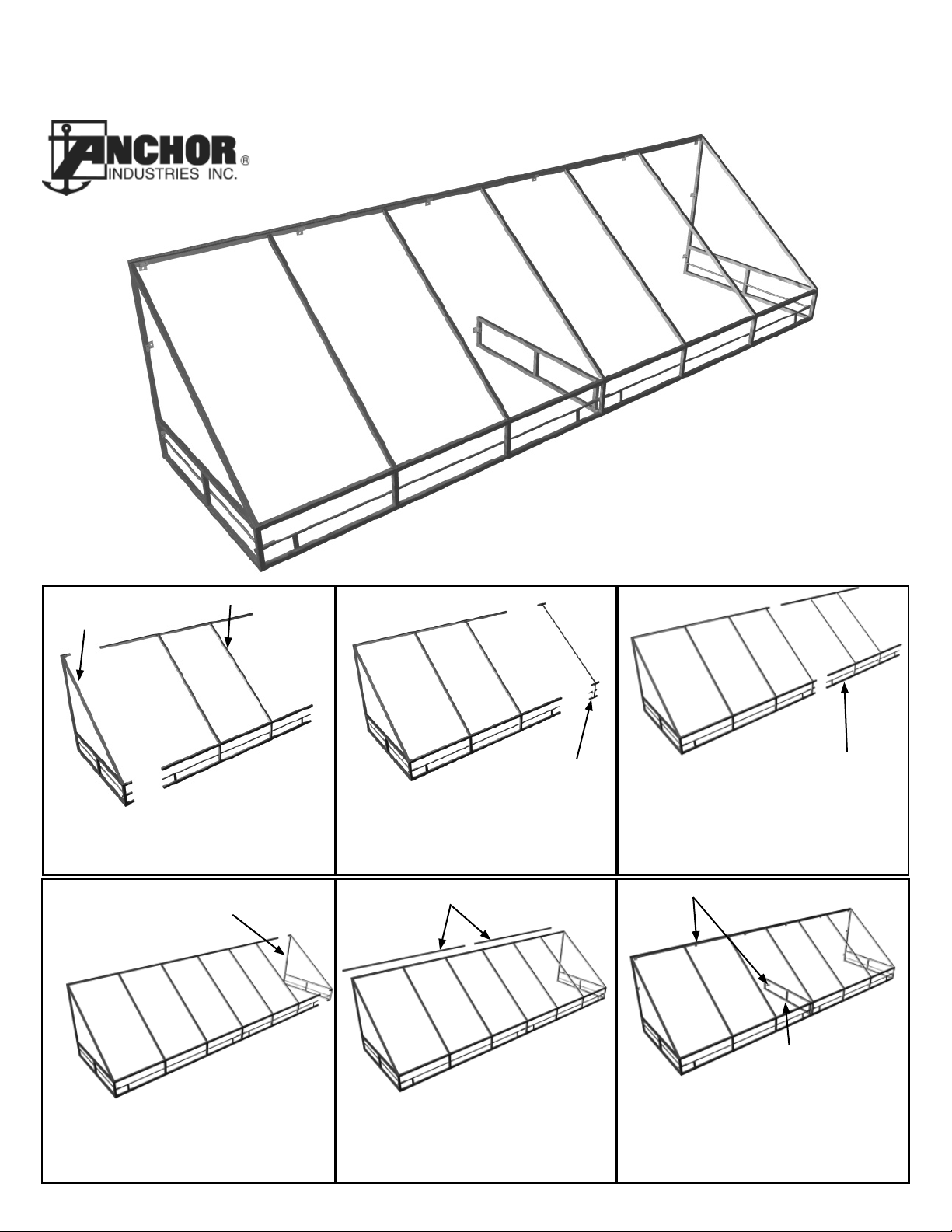
Assembly Instructions
E-Z Connect Frame
Closed End
Section - Left
Middle Section
Step 1
Fit Closed End Section to Middle Section. (Details 1 & 3)
Closed End
Section - Right
Fully Constructed Frame
Intermediate
Rafter Section
Step 2
Fit Middle Section to Intermediate
Rafter Section. (Detail 4 & 5)
Channel Rails
Middle Section
Step 3
Fit Intermediate Rafter Section to next
middle section. (Detail 4 & 5)
Z Brackets
Step 4
Fit Closed End Section - Right to last
middle section. (Details 1, 2, & 3)
EC 4125
Step 5
Attach Channel Rail to back bar.
(Detail 2)
Support Truss
Step 6
Attach Support Truss. Mount Frame to
Wall with Z Brackets. Install Fabric Prior
to Mounting to Building.
EZC 0110
Page 2
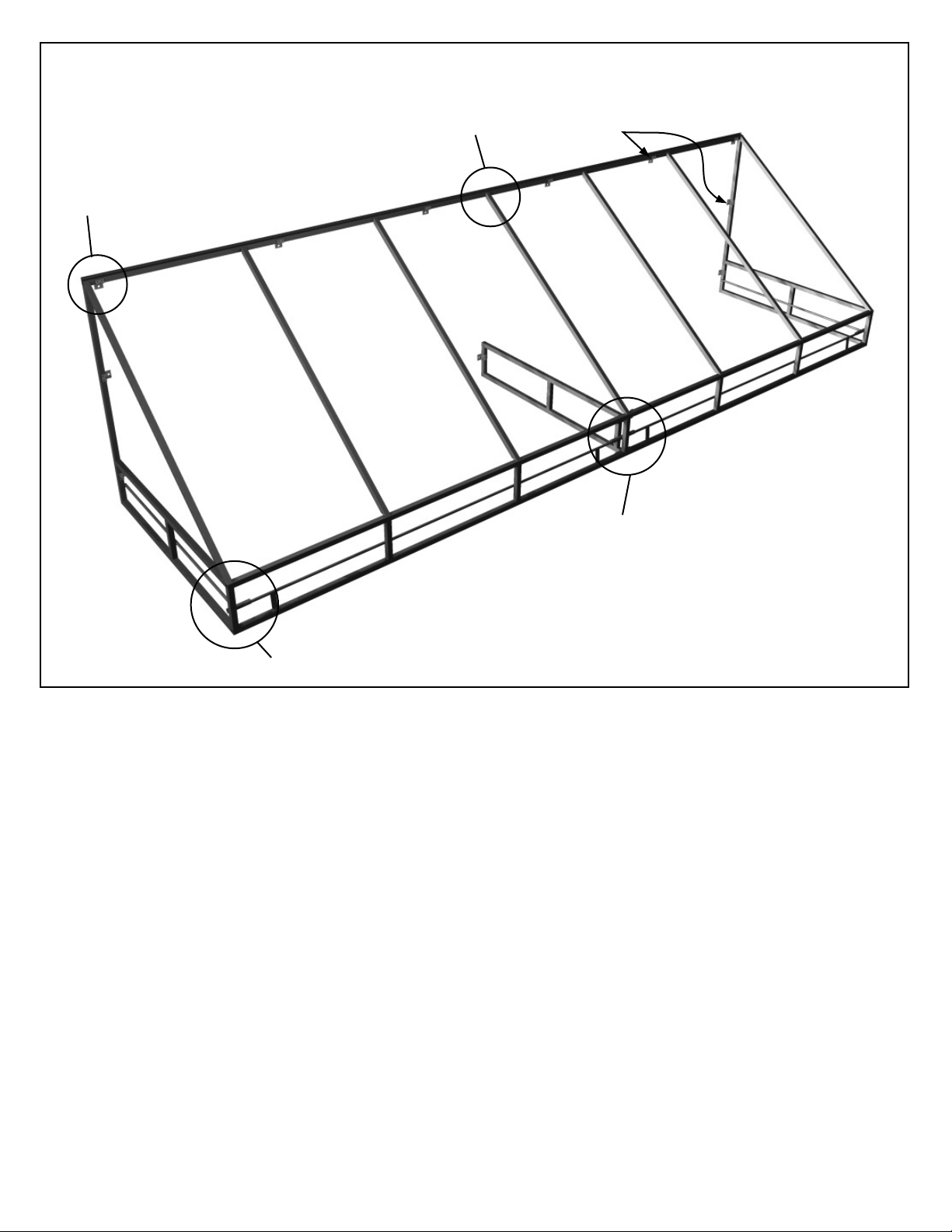
Detail 1 & Detail 2
(Back View)
Space Z-Brackets maximum
of 3’-0” apart and one at each
end of top horizontal bar.
Detail 4
Detail 5
Detail 3
Follow steps as directed on page 1. See page 3 for installation details.
To install fabric, slide top into channel rail. Pull fabric tight and lace into position.
2
Page 3

DETAIL 1
Channel rail
#12 x 3/4” Self-Drilling
Screw fastens Z-Bracket
to Frame.
1 1/4”
Use 3” Lag Screw to fasten
to Building, plus expansion
shield when requested for
installation to brick. (See
Note 1)
Closed End
Section
#12 x 3/4” SelfDrilling Screw.
DETAIL 2
Channel rail
Closed End
Section
#12 x 3/4” SelfDrilling Screw.
DETAIL 3
Lace Bar
Middle Section
DETAIL 5
1 1/4”
Typ.
#12 x 3/4” SelfDrilling Screw. Typ.
Closed End
Section
Intermediate Rafter
Section.
1 1/4”
Typ.
#12 x 3/4” SelfDrilling Screw. Typ.
DETAIL 4
Top horizontal bar of
Middle Section.
Lace Bar
1 1/4”
Typ.
#12 x 3/4” Self-Drilling
Screw. (Typ.)
Place on bottom surface
of top horizontal bar.
Intermediate Rafter
Section.
Note 1:
Attachment to Building is the responsibility
of the installer. The hardware that is provided may not be adequate for all applications. Installers should insure that awning
is safely and securely installed.
#12 x 3/4” SelfDrilling Screw. Typ.
3
Page 4

EVANSVILLE, INDIANA
Thank you for purchasing an Anchor Product. In return, we pledge Quality, Service and Craftsmanship and are available for
any questions you may have or assistance you may need.
PHONE NUMBER
812-867-2421
FAX NUMBER
812-867-1429
Please read installation instructions before the installation or removal of this product. Installation instructions are also
available at www.anchorinc.com
CAUTION
Anchor products are of superior design and operate best within the parameters of these instructions. It is imperative that the
instructions be carefully read and completely followed.
For each installation, the installer is solely responsible for evaluating the site for the proper securing methods and fasteners
to be used. Standard fasteners furnished may be inadequate, site unseen by Anchor, thus requiring additional or alternate
method of fastening.
Inasmuch as the weather is unpredictable, good judgment and common sense must be incorporated within installation
guidelines. Proper safety equipment should be used at all times to insure a safe installation and take down. We suggest a
careful evaluation be made to determine safety equipment needed, such as hard hats, steel-toe shoes, safety glasses and
other as required.
*Anchor stands behind its products in accordance with its standard Terms and Conditions of sale. A copy of our Terms and
Conditions of Sale can be obtained by contacting Anchor at the telephone number and/or address on this document.
1-800-255-5552
1100 Burch Dr. • PO Box 3477 • Evansville, IN 47733, USA
Phone: 812•867•1429
Email: custdiv@anchorinc.com • www.anchoinc.com
29.0 7-31-02
 Loading...