

Page 1
Assembly Instructions
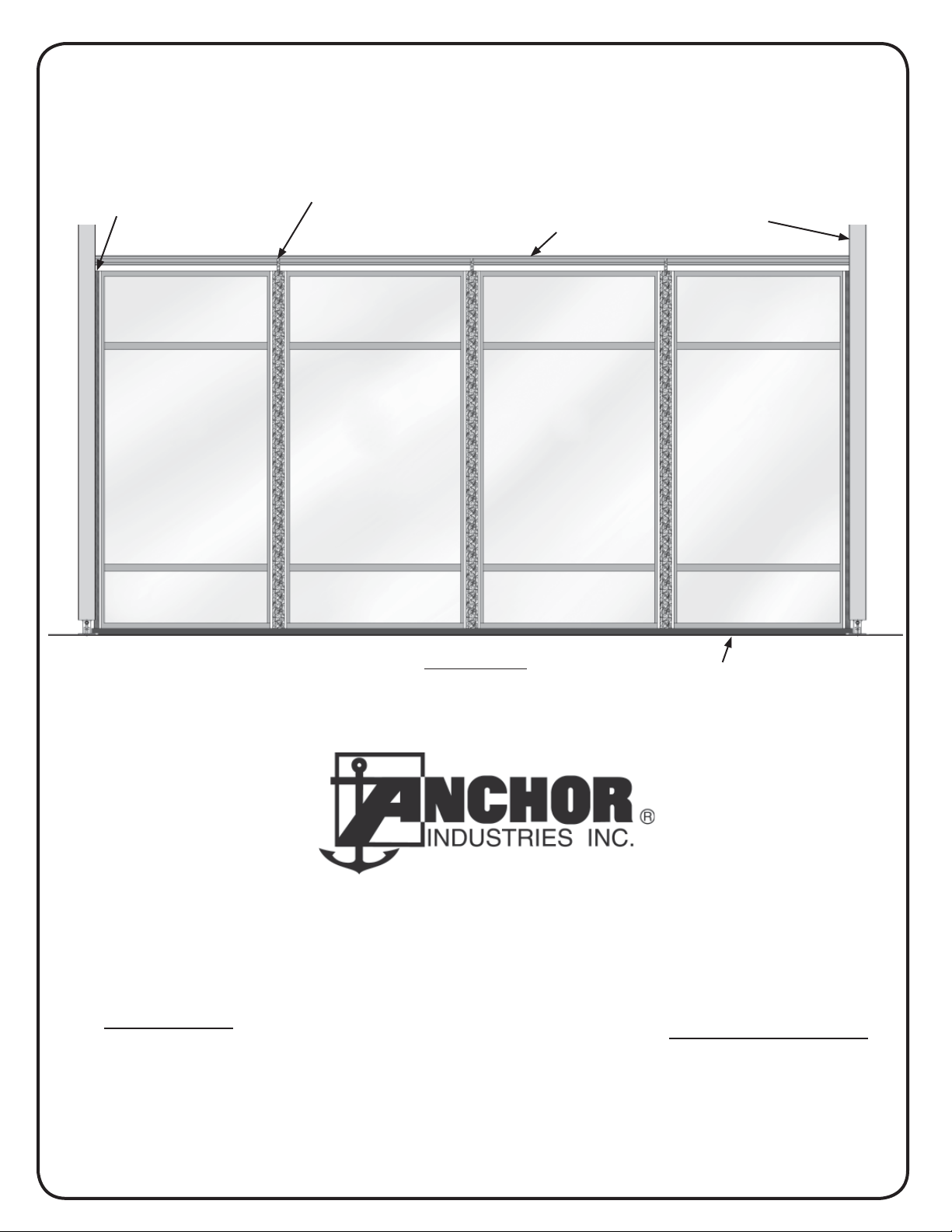
Window/Hard Wall Installation
U-Channel with
Rubber seal (typ.)
Wall Panel
Intermediate Post Assembly
with Adapter Fork and Pressure
Plate (typ.)
Purlin
Wall Panel Wall Panel
Building Upright
(typ.)
Wall Panel
ELEVATION
Outside View
Wall Base
Please read all assembly / installation instructions before the installation or removal of this product.
PHONE: 812-867-2421
SALES OFFICES:
1100 BURCH DRIVE
PO BOX 3477
EVANSVILLE, IN 47733 USA
FAX: 812-867-0547
1-800-544-4445
EMAIL: tents@anchorinc.com
www.anchorinc.com
PRODUCTION FACILITIES:
EVANSVILLE, IN
EC3811
WHW 1108
Page 2
INSTALL KIT ASSEMBLY AND WALL PANEL INSTALLATION
1. Install the wall base equally spaced between the
uprights. Position the wall base so that the back lip
is toward the interior of the tent. See Figure 1.
2. Install the U-Channels in the uprights by engaging the “L” leg into the outside kedar groove of the
Building Upright and
Base Plate
Notch that
receives Uchannel
Back lip
upright and rotating the U-Channel toward the interior of the tent until the flat portion of the “U” contacts
the upright. At this point, if the wall base is positioned correctly, the U-Channel will drop down into
To inside of
Building
the notch at each end of the wall base.
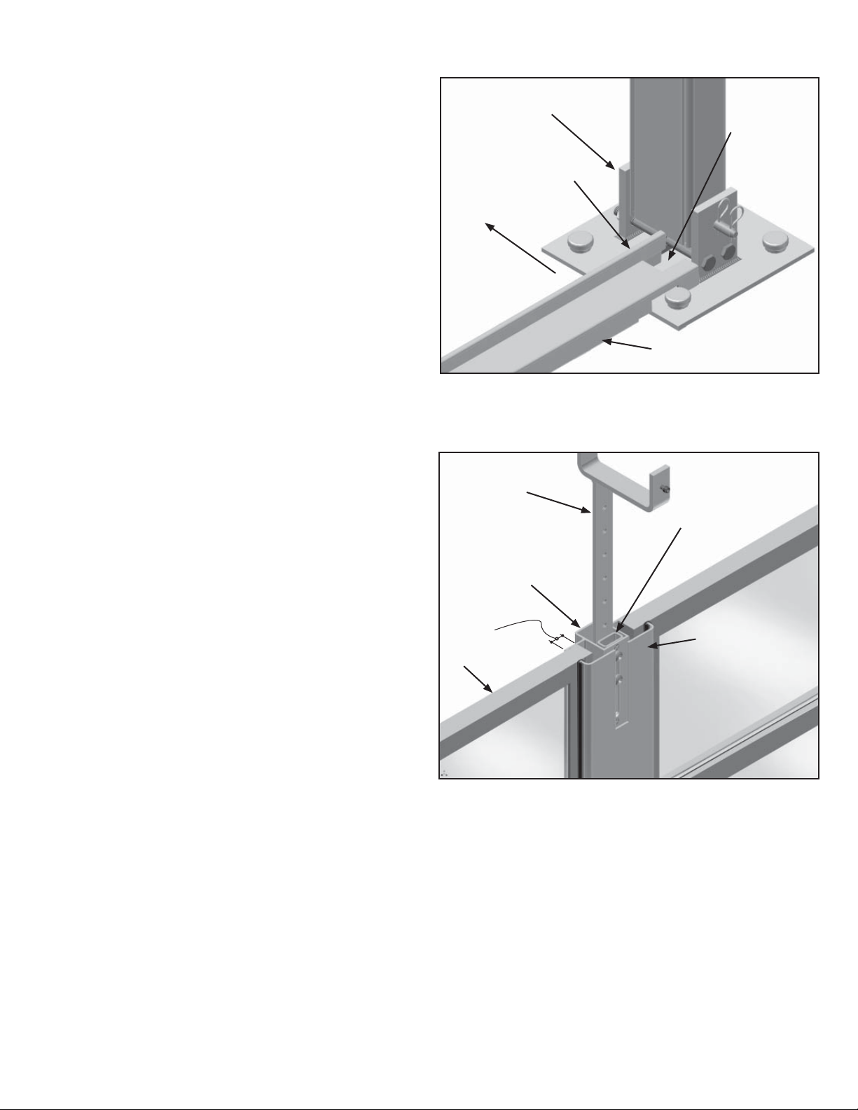
3. Remove the bolts, washers and pressure plates from
all of the intermediate posts. Save for re-use after
the wall panels are installed.
4. Remove the bolts and washers from the adapter
Wall Base
Figure 1
forks and slide the vertical portion of the fork inside
the top of the post, but outward of the spacer tube inside the post. See Figure 2.
Note: DO NOT insert the fork inside the spacer tube. Re-install the washers and bolts in the vertical por-
tion of the adapter fork and loosely tighten so the fork is allowed to slide in and out.
5. At about 48” away from the side U-Channel, position the first intermediate post on the wall base so
that the “Z” clip on the bottom of the post engages
the back lip of the wall base. See Figure 3. Rotate
the post to a plumb position while engaging the “U”
Adapter Fork
Spacer Tube
portion of the fork with the purlin above. Slide the
adapter fork up until the bottom of the “U” portion of
the fork contacts the bottom of the purlin. Snuggly
tighten the bolts that fasten the fork to the post.
Note: These bolts and the setscrew in the fork must
be securely tightened once the wall panels are in
position.
Intermediate
Post Assembly
Approx. 3/4”
overlap.
Wall Panel
Pressure Plate
6. The install kit assembly is now ready to receive the
first wall panel.
7. The orientation of the wall panel is correct when the
smaller pane of glass is on the bottom and the glazing stops are toward the interior of the tent.
Figure 2
8. First engage one side of the wall panel into the UChannel, then pivot the opposite side toward the intermediate post until the inside face of the wall panel
contacts the lip on the wall base. (Note: If the intermediate post is in the way, slide it out of the way to allow
the panel to pivot back against the lip on the wall base.) Once the wall panel is in place, slide the intermediate post back toward the wall panel until the leg of the post overlaps the outside face of the wall panel by
approximately ¾”. Install the pressure plate to the intermediate post, but do not tighten the bolts so that the
adjoining wall panel can be placed on the opposite side of the intermediate post. See Figure 2.
2
Page 3

9. Install the second wall panel by placing it on the wall
base and sliding the side between the intermediate
post and the loosely installed pressure plate. Install
the second intermediate post as noted above in step
5 and slide the intermediate post toward the wall
Intermediate post (without
pressure plate)
panel until the leg of the post overlaps the wall panel
approximately ¾”. Loosely install the pressure plate
Wall Base
as described in step 8.
10. Before installing the third panel, install the fourth
panel adjacent to the upright by installing the UChannel in the upright and installing the third (& last)
intermediate post as described in steps 2 – 8. Leave
the pressure plate off the third intermediate post until
the third (& last) wall panel is in place.
11. Now the third wall panel can be placed between the
Inside of Building
second and third intermediate posts. The intermediate posts may need to be spread apart to allow the
placement of the third wall panel. Once the third
Z-clip
panel is in place, secure the pressure plate on the
third intermediate post.
12. Before tightening the bolts securing the pressure plates to the intermediate posts, adjust the wall panels and intermediate posts so they are equally spaced and the intermediate posts are plumb.
13. Tighten all the pressure plate bolts, adapter fork
bolts and the setscrews securing the adapter forks
to the purlin.
U-Channel
14. Finally, install the rubber seals between the UChannels and the interior face of the wall panels.
Note: It’s best to begin engaging the seal at either
the top or the bottom and work to the opposite end.
Rubber Seal
Wall Panel
See Figure 4.
Figure 3
Wall Base
Inside of Building
Figure 4
3
Page 4

EVANSVILLE, INDIANA
PHONE NUMBER
812· 867· 2421
FAX NUMBER
812· 867· 0547
Anchor products are of superior design and operate best within the parameters of these instructions. It is imperative
that the instructions be carefully read and COMPLETELY FOLLOWED. Please read installation instructions before the
installation or removal of this product. Installation instructions are available online at www.anchorinc.com or by calling
1-800-544-4445.
CAUTION:
1. For each installation, the installer is solely responsible for evaluating the site and the proper securing method
determined. Some soils require different staking or securing than that provided with the tent. Due to this variety of
soil conditions, these are the manufacturer’s suggested sequence of installation procedures. Anchor’s responsibility
is limited to the manufacture of the tent parts and materials. We are not responsible for methods that installers may
choose to erect and secure the tent to the ground.
2. The number of stakes suggested in the installation instructions does not necessarily meet all or any relevant codes
on the site of the tent installation. The number of stakes suggested will, in many cases, keep the tent erected,
however, due to various soil conditions; these stakes will be insuf¿ cient to keep the tent secure in high winds.
It is the tent installer’s responsibility, not the manufacturer, to determine the appropriate number of stakes to meet
the necessary wind loads on the site. Regardless of the number of stakes we suggest, we make no representation
or warranty as to whether this speci¿ c number of stakes will meet the local tent code. Anchor does not, nor can
it make any suggestions, representation, or warranties about the adequate staking required at each speci¿ c
installation site. Staking information provided in the installation instructions is not a suggestion about what is
necessary to meet a site-speci¿ c load.
For additional assistance, consult: “The IFAI Procedural Handbook For the Safe Installation and
Maintenance of Tentage” and the IFAI Pocket Guide “Pullout Capacity of Tent Stakes”, both available from
the IFAI Tent Rental Division or on our website.
3. Inasmuch as the weather is unpredictable, good judgment and common sense must be incorporated within
installation guidelines. It is the responsibility of the tent installer/maintainer to determine the severity of the weather,
proper time and method of installation and/or erection and disassembly. Note: We recommend that snow and
ice be removed from the tent surface as soon as possible because accumulation will damage the tent
or fabric structure. Please consult with our Engineering Department about the maximum loads for each
product.
This product has been manufactured for use as a temporary structure. For the safety of all occupants, evacuation
is recommended if threatening weather occurs, or if there is any doubt concerning the safe use of this product.
4. Proper safety equipment should be used at all times to insure a safe installation and take down. We suggest a
careful evaluation be made to determine safety equipment needed, such as hard hats, steel-toe shoes, safety
glasses and other as required. It is our desire that all installations are safe. Please be aware of hidden dangers
both underground, i.e., gas lines, water lines, electrical lines, etc. and above the tent such as power lines and
telephone lines.
5. Anchor stands behind its products in accordance with its standard Terms and Conditions of sale. A copy of our
Terms and Conditions of Sale can be obtained by contacting Anchor at the telephone number and/or address on
this document.
28.2 04-29-08
 Loading...