

Page 1
Liner Installation Instructions
for Event & Venue Series
Anchor Structures
Liner for Mid
Gable End Liner
with Mid Attached.
Important: Read these instructions BEFORE frame assembly.
Note: If there is no access to the bottom rafter kedar channels, kedared buckles must be inserted into the
appropriate channels BEFORE rafters are attached to frame. See step 9 for instructions. Disregard if there is
access to the bottom rafter kedar channels.
Eave cables must be attached to uprights. This may be done just prior to liner installation. See step 5.
SALES OFFICES:
1100 BURCH DRIVE
PO BOX 3477
EVANSVILLE, IN 47733 USA
PHONE: 812-867-2421
FAX: 812-867-0547
1-800-544-4445
E-MAIL: tents@anchorinc.com
www.anchorinc.com
PRODUCTION FACILITIES:
EVANSVILLE, IN
LEV 0413EC4665
Page 2
Ridge Insert Weldment
Ridge Insert Weldment
upright bracket
Liner
Liner
SIDE VIEW FRONT VIEW
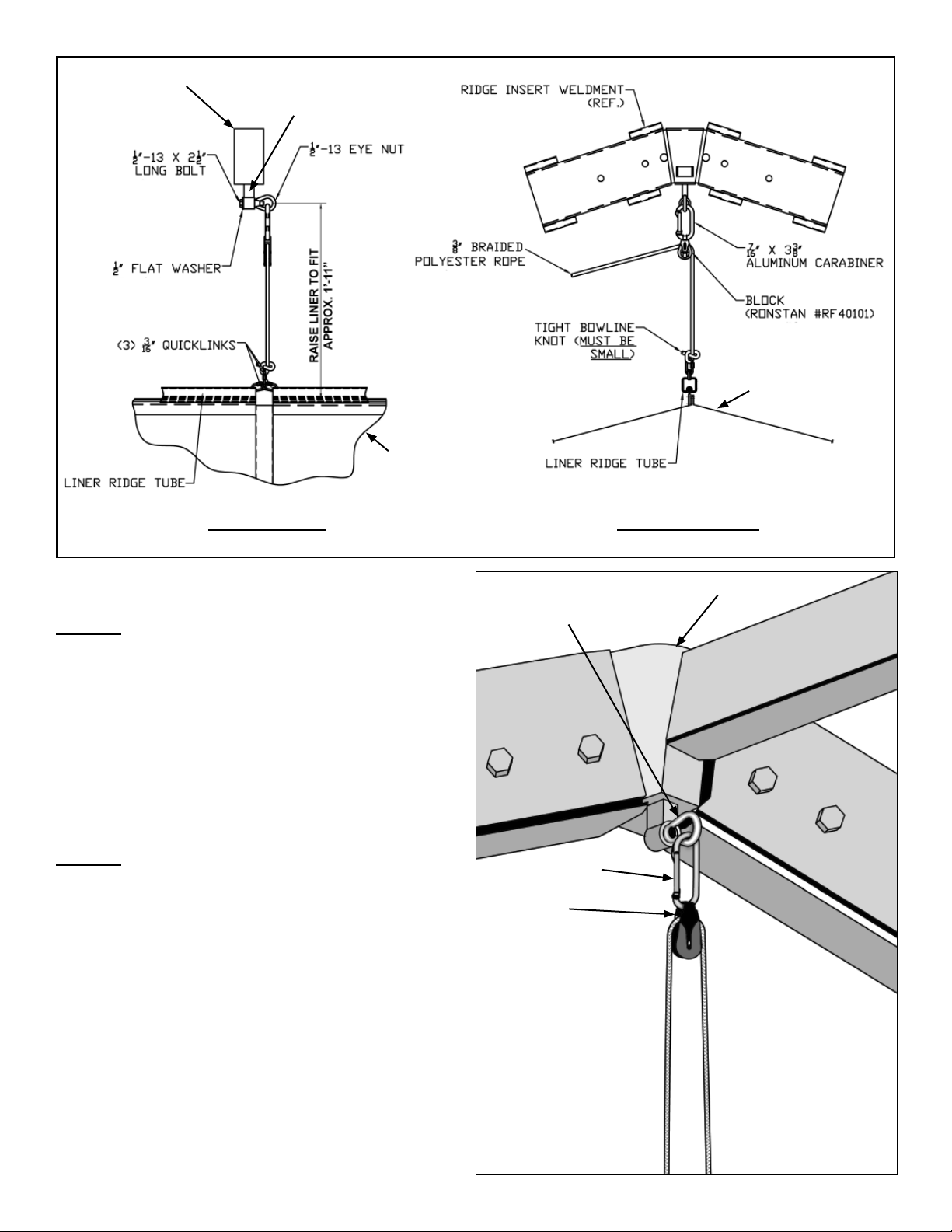
Step 1
The liner will be hoisted by ropes attaching to
eyenuts that are attached to the peak weldment
upright location as shown in Figure 1.
It will be easier to install these bolts and eyenuts
if it is done before the frame is raised or the
fabric is installed. Place one eyenut at each
peak weldment with all eyenuts facing the same
direction except at (1) end.
Step 2
Lay out liner pieces on drop cloths in their
respective placements. Check the pieces to
be sure velcros go together correctly and the
good side of the liner faces the ground. Please
note that gable ends are built into adjacent mid
pieces.
Bolt with eyenut thru
peak weldment upright
location.
Carabiner
Block
Figure 1
Ridge Insert Weldment
Figure 2
2
Page 3
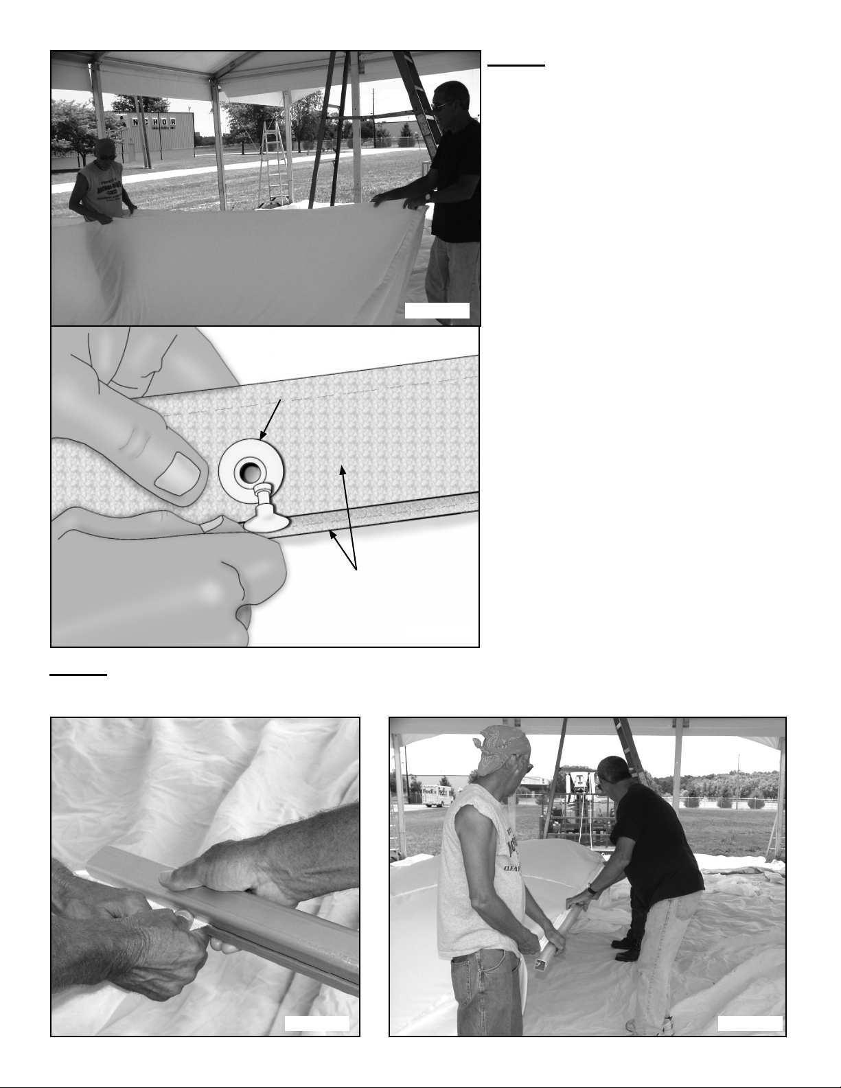
Menax fastener
Step 3
Join pieces together with Velcro, menax fasteners and side release buckles at ridge and eaves.
(Figures 3a and 3b)
Figure 3a
Velcro at edges of
liner mids.
Figure 3b
Step 4
Feed each ridge kedar into channel of liner ridge tube. (Figures 4a and 4b)
Figure 4a
Figure 4b
3
Page 4

Step 5 - For Event
Eave cables with turnbuckles are required for liner installation. Slide the Liner Eave Bracket onto the interior side of the
upright. Fasten by tightening screw and eyebolt into upright channels as shown below. Attach quick link and cables as
shown in Figure 5b. See Figure 5c for Gable End Cable attachment. Twist Turnbuckles until cables are taut.
Eave
Rafter
Quick link
(2) Eyebolts and (1) screw are included
with each bracket. Use two eyebolts
where cables are required in adjacent
bays.
Purlin
Mid Liner Cable
Liner Eave Bracket
Rafter
Gable End Purlin
Gable End Liner Cable
Gable End Cable & Mid
Liner Cable fasten into
same eyebolt on Liner
Eave Bracket.
Figure 5a
Eave
Purlin
Upright
Upright
Mid Liner Cable
Liner Eave Bracket
Turnbuckle
Gable End Liner Cable
Turnbuckle
Quick Link
Figure 5b
Mid Liner Cable
Gable End Fabric
4
Butt Liner Eave
Bracket up against
purlin bracket.
Figure 5c
Figure 5d
Page 5

Step 5 - For Venue
Eave cables with turnbuckles (Figure 5f) are required for mid liner installation. Loosen nuts and bolts at location shown in
Figure 5e, slide L-bracket in place and tighten bolts. Adjust turnbuckle until cable is tight.
L-Bracket
Quick Link
Mid Eave Bar
Gable end
L-Bracket
Cables for mid fastens into
L-Bracket
Figure 5e
Step 6
Attach quick links and tie pull rope as shown in Figures 6a & 6b. Run rope thru eyenut as shown in Figure 2. Run rope back down and behind eave cable as shown
in Figure 6c. All ropes should run to the same side for an even fi t.
Quick links
Liner Ridge Tubes
Turnbuckle
L-Bracket
Venue Mid Eave Liner Cable
Figure 5f
Figure 6a
Figure 6b
5
Page 6

Eave Cable
Pull Rope
Figure 6c
Step 7
With one person holding each rope, pull the
liner up in unison until the ridge tubes are
above the eave line. Tie ropes off to bottom of
upright as shown in Figure 7b.
Liner being raised.
Step 8
At eave line, hook liner eave hooks to eave cable as shown
in Figure 8. After all hooks are connected, raise liner to
fi nal position and tie off as shown in Figure 7b.
Eave beam
Eave cable
Figure 7a
Figure 7b
View looking up at eave.
Figure 8
6
Page 7

Step 9
Before assembling rafters to frame,
kedared buckles must be inserted into the
bottom channel of the rafters. Examine the
gabled end liner that fi ts to the particular
rafter. Count the number of female side-release buckles on the slopes of that gable end
and insert the correct number of matching
kedared buckles into each bottom channel of
the corresponding rafter.
Kedared buckles inserted
into bottom channel of rafter
at gable end awaiting gable
end liner for connection.
Figure 9a
Ridge
Gable end
eave beam.
Snap buckles together and
tighten strap until liner has
the proper shape.
Do not over-tighten straps.
Kedar
Figure 9bFigure 9c
Male side release
buckle
Kedared buckle
Step 10
Snap kedared buckle to gable ends and adjust to create desired look at gable end slope.
Note: If liner appears loose after all kedared buckles are adjusted, pull-up ropes may require readjustment.
Gathered Liner Shown
7
Page 8

EVANSVILLE, INDIANA
PHONE NUMBER
812· 867· 2421
FAX NUMBER
812· 867· 0547
Anchor products are of superior design and operate best within the parameters of these instructions. It is imperative
that the instructions be carefully read and COMPLETELY FOLLOWED. Please read installation instructions before the
installation or removal of this product. Installation instructions are available online at www.anchorinc.com or by calling
1-800-544-4445.
CAUTION:
1. For each installation, the installer is solely responsible for evaluating the site and the proper securing method
determined. Some soils require different staking or securing than that provided with the tent. Due to this variety of
soil conditions, these are the manufacturer’s suggested sequence of installation procedures. Anchor’s responsibility
is limited to the manufacture of the tent parts and materials. We are not responsible for methods that installers may
choose to erect and secure the tent to the ground.
2. The number of stakes suggested in the installation instructions do not necessarily meet all or any relevant codes
on the site of the tent installation. The number of stakes suggested will, in many cases, keep the tent erected,
however, due to various soil conditions; these stakes will be insuf¿ cient to keep the tent secure in high winds.
It is the tent installer’s responsibility, not the manufacturer, to determine the appropriate number of stakes to meet
the necessary wind loads on the site. Regardless of the number of stakes we suggest, we make no representation
or warranty as to whether this speci¿ c number of stakes will meet the local tent code. Anchor does not, nor can
it make any suggestions, representation, or warranties about the adequate staking required at each speci¿ c
installation site. Staking information provided in the installation instructions is not a suggestion about what is
necessary to meet a site-speci¿ c load.
For additional important information, consult: “The IFAI Procedural Handbook For the Safe Installation and
Maintenance of Tentage” and the IFAI Pocket Guide “Pullout Capacity of Tent Stakes”, both available from
the IFAI Tent Rental Division or on our website.
3. Inasmuch as the weather is unpredictable, good judgment and common sense must be incorporated within
installation guidelines. It is the responsibility of the tent installer/maintainer to determine the severity of the weather,
proper time and method of installation and/or erection and disassembly. Note: We recommend that snow and
ice be removed from the tent surface as soon as possible because accumulation will damage the tent
or fabric structure. Please consult with our Engineering Department about the maximum loads for each
product.
This product has been manufactured for use as a temporary structure. For the safety of all occupants, evacuation
is recommended if threatening weather occurs, or if there is any doubt concerning the safe use of this product.
4. Proper safety equipment should be used at all times to insure a safe installation and take down. We suggest a
careful evaluation be made to determine safety equipment needed, such as hard hats, steel-toe shoes, safety
glasses and other as required. It is our desire that all installations are safe. Please be aware of hidden dangers
both underground, i.e., gas lines, water lines, electrical lines, etc. and above the tent such as power lines and
telephone lines.
5. Anchor stands behind its products in accordance with its standard Terms and Conditions of sale. A copy of our
Terms and Conditions of Sale can be obtained by contacting Anchor at the telephone number and/or address on
this document.
28.2 03-04-09
 Loading...