

Page 1
20 Meter
800-544-4445 • 812-867-2421
www.anchorinc.com
3M Uprights
Page 2
X-CABLING PATTERNS
For Anchor Structures
20m Span
(220 x 100 x 4mm Profile)
2-28-05
EAVE
EAVE
EAVE
EAVE
EAVE
EAVE
PRIMARY
ROOF
CABLES “X”
SIDE CABLES
1
6
5
432
321
3
21
Following the same (6) open bay rule...
The 16th bay must be x-cabled.
And, the 23rd, etc.
654
3
2
1
65432
1
43
2
1
6
5432
165
43
21
6
5
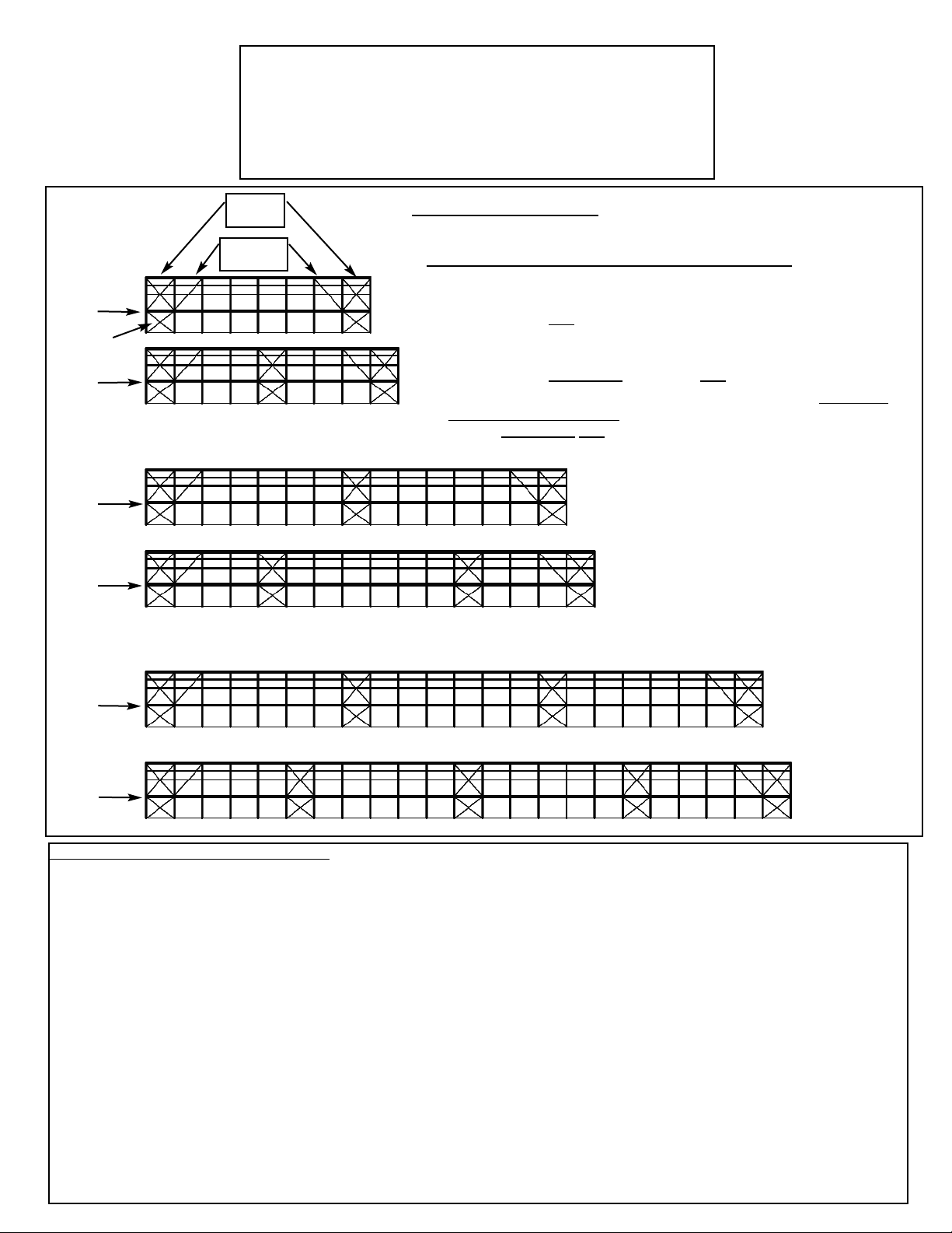
X-CABLING GENERAL INFORMATION:
NOTE: THIS INFORMATION IS CONSISTENT WITH CURRENT ENGINEERING DATA AND SUPERSEDES ANY
OTHER CABLING GUIDELINES DESCRIBED IN THIS INSTALLATION MANUAL.
For safety, X-cabling must be installed according to the above, engineered pattern. Unless it is properly cabled, the beam
system can fall in even moderate winds. It is the customer’s responsibility to follow the patterns shown above, which have
been approved by engineering analyses to ensure the safety of the structure. Secondary cables are added to the second
bay only and do not include side cables. The interior cabled bays may be positioned in any manner that avoids having (6)
consecutive side bays without cabling.
If the rafters of your 20m frame are spliced (keystoned) at 15m or 10m, the roof cables may be in two sections spliced endto-end. This 2-piece construction lets you remove the upper sections of the cables and use the lower sections on your 15m
or 10m frame. If your 20m frame is a reduction of a 25m frame, you can add 2.5m upper sections to the roof cables to
accomodate the full 25m span.
When installing x-cabling, it is best to attach all cables before tightening any of them. Then begin at ground level and tighten the cables in ascending order. The x-cabling should be used to establish a good vertical alignment of the beams either
by plumbing the beams or by using a careful visual sighting. Good alignment of the beams will improve the appearance of
the structure and make fabric installation easier.
SECONDARY
ROOF
CABLES “V”
SIDE VIEWS SHOWN
1. All 20m Structures require primary roof and side x-cabled end bays.
2. Structures with 6 or more total bays also require secondary x-cables in
the roof section only
of the second bays. Viewed from above, these form
a “V” shape. (Structures with 5 bays or less do not require secondary
cables in the second bay.)
3. No more than 6 consecutive
non-cabled side
bays are permitted.
4. After the 6th open side bay, an additional x-cabled bay with full primary
roof cables and side cables must be added to the interior, so that no more
than (6) consecutive side bays are non-cabled.
ENGINEERING RULES FOR PROPER X-CABLING
Page 3

BT 2000 240/300 570/627
Copyright: Without our written consent the disclosure, reprinting,
copying and reproduction of this publication, whether in full or in
part, are prohibited.
2
Spanning the world.
Page 4

BT 2000 240/300 570/627
Index
1 Introduction..............................................................................4
1.1 General notes ...................................................................................... 5
1.2 Construction tools ............................................................................... 7
2 Staightening of the tent any laying of the baseplates.................8
2.1 Laying of the baseplates ...................................................................... 8
3 Construction of the tent..........................................................13
3.1 Pre-assembly of the legs, beams and wind bracings .......................... 13
3.2 Mounting of the components ............................................................. 18
3.3 Mounting of the wind bracings .......................................................... 22
4 Erection of the tent .................................................................25
4.2 Mounting problems and their causes ................................................. 32
4.2.1 The corner- and middle legs do not fit to the baseplate receiver . 32
4.2.2 The baseplate pins cannot be fixed tight ..................................... 32
5 Mounting of tent’s covers .......................................................34
5.1 Pulling up the roof cover.................................................................... 34
5.2 Stretching of the roof cover (model with fixed tensioning) ................. 37
5.3 Stretching of the roof cover (model with rubber tensioning) .............. 39
5.4 Pulling in the gable covers (gable triangle)......................................... 40
5.5 Pulling in the sides- and gable walls.................................................. 40
5.6 Mounting of the ground rail (if provided) ........................................... 42
6 Dismantling ............................................................................43
7 Service notes ..........................................................................44
7.1 Construction of the tent..................................................................... 44
7.2 Bedding and transport ....................................................................... 44
7.3 Routine visual inspection ................................................................... 44
8 Ratings ...................................................................................45
8.1 Construction of the tent..................................................................... 45
8.2 Tent covers........................................................................................ 47
8.3 DIN ISO Normen................................................................................. 47
3
Spanning the world.
Page 5

BT 2000 240/300 570/627
1 Introduction
The following instructions describe in a methodical plan the construction and
erection of your RÖDER tent.
Follow always these instructions.
Work from point to point.
If it is necessary, there are extra points, in which you have to take care or pay
special attention.
Please pay attention to the appropriate safety regulations for
prevention of accidents.
Regarding the contents of this document:
The points 1-5 describe the construction of the tent. The points 6-8 repeat
additional technical informations, maintenance and dismantling’s instruction.
The drawings are made to show clearly the construction and dismantling
procedures and also for the identification of the separate building
components.
It has to be pointed out that the pictures, do not always correspond to the
real dimension and size. Explanations and/or notes have been added to
these pictures.
If you have any questions, please call
RÖDER Zelt- und Veranstaltungsservice GmbH in Germany on follow
numbers:
Phone ++49-6049-700 - 0 Fax ++49-6049-700 - 339
4
Spanning the world.
Page 6

BT 2000 240/300 570/627
1.1 General notes
Before starting construction you must read this documentation exactly. If the
points are clear and the building components are identified and ready, then
start construction and follow the instructions step by step.
Pay attention to the safety regulations for prevention of accidents.
The life of the helpers may be in danger due to the lack of knowledge and
poor observation of the given regulations.
Work on every point of the instructions chronologically.
For the construction of the tent there has to be a minimum of 6 people.
Notes on safety:
The joining of the ropes has to be stretched after mounting.
The taking out of the ropes is not allowed.
Use the supplied construction tools for the installation.
Pay attention to the pins, that they are fixed solid after mounting.
Pay attention to the purlins and to the intermediaite purlins to erect them
always correctly.
During mounting wear protective clothing according to your work to prevent
injuries.
Replaced used or damaged components with original new ones.
Pay attention to:
You have to keep the relevant safety appliances and standart specifications.
(Employer’s liability insurance association).
The construction helpers have to be instructed about the possible dangers
before construction begins.
The supervision and the responsibility has to be taken by an expert person
during the construction.
Expert is the person who knows about the operating cycle and the requisite
safety precautions.
5
Spanning the world.
Page 7
BT 2000 240/300 570/627
Measuring rod 5m
Fork 140mm
Mounting rods
Fork 80mm
Pic. 1
6
Spanning the world.
Page 8

BT 2000 240/300 570/627
1.2 Construction tools
The construction and dismantling has to be done with the respective
construction tools.
Special provided tools for the construction:
1.2.1 Measuring rod
1.2.2 Mounting rod 6m,
1.2.3 Mounting rod 4m,
1.2.4 Leading-in conductor for covers 2x
1.2.5 Bracing devices for tent‘s covers
More construction tools and working substance prepared for the structure:
At least 3x traction cable with carabine swivel (at least 250 daN carrying
force)
2x double ladder equivalent the height of tent’s side
1x spanner SW 17
2x spanner SW 24
1x handspike
2x aboutsledge
10x squared beam 80 x 80 x 400 mm
1x pincers
2x measuring tape 30 m
1x directional cord (at least double the length of the tent)
1x optional: peg puller (for dismantling recommended)
1x Crane or fork stacker with telescope jib with hoisting height 8-10m
mounting drawing cage.
7
Spanning the world.
Page 9
BT 2000 240/300 570/627
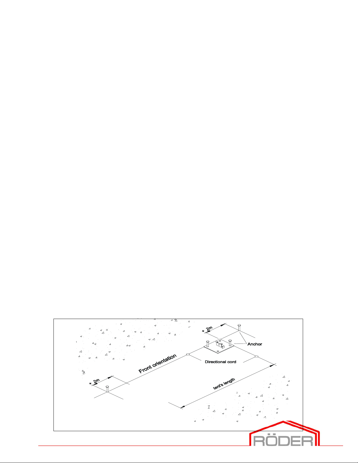
2 Straightening of the tent and laying of the baseplates
The main topology of the tent has to be straighten locally (e.g. road course,
front of houses etc.). It has to be carefully and exactly positioned, by lying
and straightening of the baseplates. The wrong placing of the baseplates will
incurr difficulties to the whole construction. Pay attention to the list of point
8.1, page 42. The borings of each baseplate for the given legs have to be
equivalent to the numbers of the earth anchors for placing.
Prepared assembling auxiliaries:
Construction tools: Building components:
Measuring rod All the provided baseplates 4-hole and 6-hole
Measuring tape For every baseplate equivalent number of earth-anchors
Directional cord For every baseplate a baseplate pin
Aboutsledge
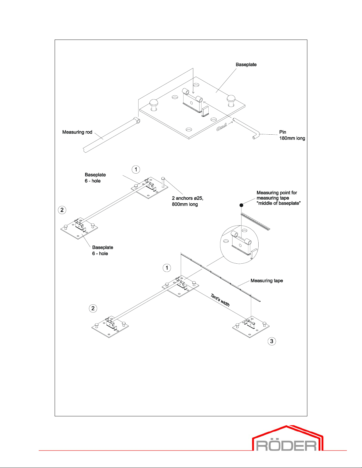
2.1 Laying of the baseplates
Indentify and assign the components according pic. 3.
Note: Do not beat the earth-anchors at all, leave about 5 cm
providing for adjustment.
The safety brackets of the baseplates are facing to the inside of the tent.
2.1.1 Choose a front orientation.
2.1.2 Stretch the directional cord (tent‘s length + 2m each side).
2.1.3 Adjust 1. baseplate parallel to the directional cord of the right angle
and fix it with the 2 earth-anchors (do not beat in the earth-anchors
`all the way).
Pic. 2
8
Spanning the world.
Page 10
BT 2000 240/300 570/627
Pic. 3
9
Spanning the world.
Page 11
BT 2000 240/300 570/627
.
Pic. 4
10
Spanning the world.
Page 12

BT 2000 240/300 570/627
2.1.4 Mount the measuring rod with baseplate pins to the baseplate
hole)
(pic. 3).
2
2.1.5 Mount the measuring rod to the baseplate
pin
(pic. 3).
(6-hole) with the flange
1
(6-
2.1.6 Adjust the baseplate
with 2 earth-anchors.
2.1.7 Stretch the directional cord across the tent’s width and adjust it by
estimating by sight right angle.
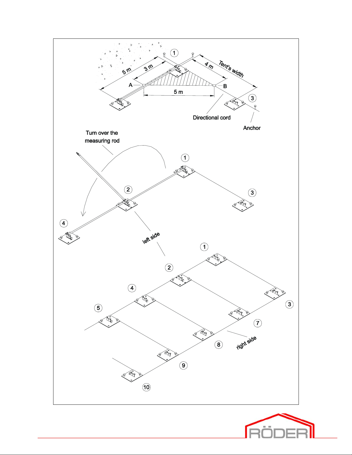
2.1.8 Measure the tent‘s width from the middle of the baseplate
middle of the baseplate
2.1.9 According to the picture measure to the mounted measuring rod
between baseplate
A). Take the measurements with the directional cord between the
1
baseplates
2.1.10 There ought to be a diagonal of 5,0m between the points A and B
(pic. 4). You have to place the directional cord in a way that between
the baseplates
and 3 exact 4,0m and mark it (point B) (pic. 4).
1
2
parallel to the directional cord and mount it
3
(6-hole) and adjust the baseplate (pic. 3).
1
and baseplate 2 exact 3,0m and mark it (point
and 3 the dimension is 5,0m.
1
until the
3
2.1.11 Adjust the baseplate
Check once more the tent’s width between the baseplates
Mount the baseplate
2.1.12 Dismantle the baseplate pin of the baseplate
measuring rod on the baseplate
2.1.13 Adjust the baseplate
measuring rod. Fix the baseplate with earth-anchors.
again to the directional cord if necessary.
3
with 2 earth-anchors.
2
(pic. 4).
4
(6-hole) to the directional cord and mount the
11
1
and 3.
1
and turn down the
Spanning the world.
Page 13

BT 2000 240/300 570/627
2.1.14 Repeat the points 2.1.12 and 2.1.13 until all the baseplates of the
tent’s side have been fixed (use 6-hole baseplates to the corners).
3
2.1.15 Mount the measuring rod to the baseplate
baseplate (4-hole) and mount the measuring rod. Check the
dimension of the tent’s width between the baseplate
already mounted baseplate. Fix the baseplate with 2 earth-anchors.
2.1.16 Repeat the point 2.1.15 until all baseplates of the tent’s side haves
been fixed.
2.1.17 Finally check the tent’s dimensions among the middle of the 4 outer
baseplates.
. Adjust the followed
2
and the
12
Spanning the world.
Page 14
BT 2000 240/300 570/627
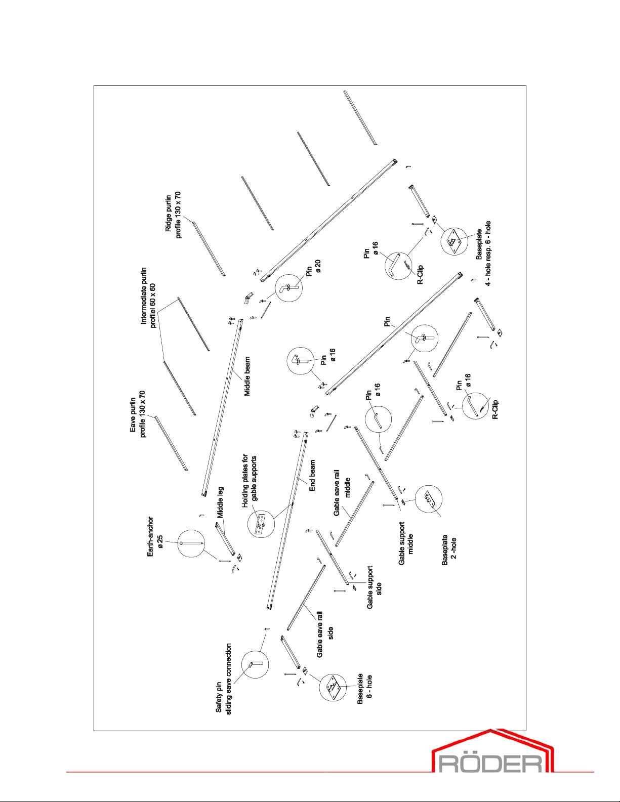
3 Construction of the tent
3.1 Pre-assembly of the legs, beams and wind bracings
Prepared assembling auxiliaries:
Construction tools: Building components:
Squared beams Endbeams
Crowbar Middlebeams
Legs
Ridge connectors
Safety stanchion for sliding eave connection
Pin Ø 20 with washer
Ridge pin Ø 16 with washer
Equivalent number of wind bracings (see 3.3)
Intermediaite purlins
Ridge purlins
Eave purlins
Gable supports
Gable eave rails
Mounting of the legs and beams
Identify and assign all the components according to the pic. 5, 6 and 7.
The components are according to the pictures. On placing proceed as
follows.
First mount only the two first bracings
3.1.1 Lay each of the corner- and middle legs between the baseplates.
3.1.2 Lay the end- and the middle beams between the baseplates.
3.1.3 Lay the ridge connector.
3.1.4 Lay and allocate the ridge struts.
3.1.5 Lay and allocate the respective mounting pins (pic. 5 - 7).
3.1.6 Lay and allocate to the endbay the gable supports and gable eave rails.
3.1.7 Lay and allocate the intermediate-, ridge- and eave purlins.
Ridge struts
.
13
Spanning the world.
Page 15
Building parts 20m-tent
BT 2000 240/300 570/627
Pic. 5
14
Spanning the world.
Page 16

Building parts 20m-tent
Endbay
BT 2000 240/300 570/627
15
Pic. 6
Spanning the world.
Page 17

Building parts 20m-tent
Normal- and bracing bay
BT 2000 240/300 570/627
16
Pic. 7
Spanning the world.
Page 18

Leg
g
Safety pin
Slidin
eave connection
BT 2000 240/300 570/627
Beam
Timber
Windbracing
Stopper
Sliding eave
Ring bolt
Pic. 8
17
Spanning the world.
Page 19

BT 2000 240/300 570/627
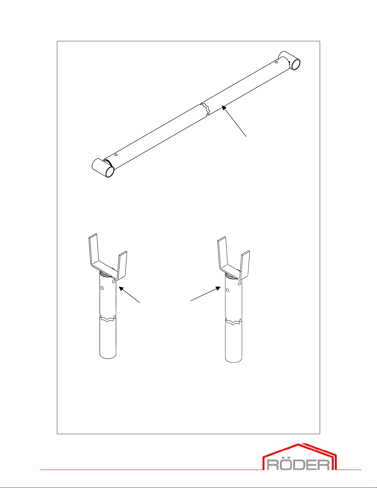
3.2 Mounting of the components
3.2.1 Connect together each of the left and right end- and middle beams
through pushing of the ridge connectors. The placing of timbers
makes the mounting easier. Place the pins (pins Ø 16 with washers) to
the equivalent borings. Pay attention that the pins fixed tightly (pic. 9).
3.2.2 Push the mounted beams into the receiver of the sliding eave
connection to the legs and push them until the limit stop. Place the
safety pin ∅ 14 to the equivalent boring through the open side of the
profile of beam (pic. 8).
3.2.3 Feed each ridge strut into the receivers and bolt them with pins (pins Ø
20 with washer). Fix the pins tight by screwing on behind the safety
bracket (pic. 10).
3.2.4 Place the legs of the bay (mounted beams and legs) into to the
baseplates. Bolt them with baseplate pins and fix the pins tight by
screwing on behind the safety bracket.
3.2.5 Mount the 2. bay according the instruction.
3.2.6 Mount the rest of the bays according to the points 3.2.1 and 3.2.2.
18
Spanning the world.
Page 20

Beam left
BT 2000 240/300 570/627
Ridge pin
Ridge
Timber
Beam right
Windbracing rope
Ring bolt
Ridge pin fixed
tight
19
Pic. 9
Spanning the world.
Page 21

Beam left
BT 2000 240/300 570/627
Stanchion pin Ø
Timber
Ridge strut
Beam right
Stanchion pin fixed
Pic. 10
20
Spanning the world.
Page 22

Tent’s length up to 40m
BT 2000 240/300 570/627
Windbracing
Free
Tent’s length over 40 m
Windbracing
Windbracing
Free fields
(max. 6)
Windbracing
Free
Windbracing 2
Pic. 11
21
Spanning the world.
Page 23

BT 2000 240/300 570/627
3.3 Mounting of the wind bracings
Mount the wind bracings (pic. 11).
Do not move them out.
Mount each of wind bracing to the first and to both last fields of the tent.
They must not be more than 6 free fields between the bracings.
If more than 6 free fields are built, then an additional wind bracing has to be
mounted.
See the picture 11 for the mounting of the brace fields.
In principle:
The wires of the wind bracings have to be mounted in the way that the
toggle-type fasteners are always set at the bottom part of the wire.
By the pre-assembly the roofing bonds have to be fastened only to a bay.
3.3.1 Prepare the wires of the wind bracings (accord. pic. 11) to the
equivalent fields.
3.3.2 Screw on the toggle-type fasteners of the side (do not screw them on
at all) Unhook the shackel.
3.3.3 Mount the ring bolts M16x120 of the roofing bonds to the ridge
connectors and fix them tight (pic. 9).
3.3.4 Feed from below the ring bolts into the endbay and screw the nut from
above, feed from above the ring bolt inside to the bay and screw it
from below with the nut. Hook the shackel (pic. 12).
3.3.5 Mount the side bonds to the corner- and middle legs according the
above instructions (pic. 8).
22
Spanning the world.
Page 24

BT 2000 240/300 570/627
Pic. 12
23
Spanning the world.
Page 25

BT 2000 240/300 570/627
Pic. 13
24
Spanning the world.
Page 26

BT 2000 240/300 570/627
4 Erection of the tent
You need a self-propelling crane or a fork stacker with telescope for the
putting of the tent (see also point 1.2).
Protect the dangerous spots during lifting.
Do not work under hanging load!
4.1.1 Put the legs of the mounted beams in to the already placed
baseplates types B. Adjust the boring, bolt the baseplate and the legs
of bay with the pin. Insert the pin from the inside of the tent to
outside. Fix tightly the pin with a R-clip.
4.1.2 Place the gable supports to their receivers of the end beams and if
provided place them the ridge connectors and bolt them. Fix them
tight by screwing down the safety bracket (pic. 18). After the
adjusting of the bay, the gable supports can be placed to the
baseplates.
4.1.3 Feed two load belts into the gravity center of bay (pic. 3) to the beams
and lift the bay with the aid of the crane or fork stacker. Place to both
sides the wires of the wind bracings. Now fix tightly to both sides the
bay with the wires after the setting upright.
4.1.4 Lift the bay slowly and take care that is not going to be twisted.
4.1.5 Place the bay vertical and fix it tight with the wires of the wind
bracings. The helpers are supporting the legs. Lay the wires of the
wind bracings to both sides and fix them tight by beating in the
anchors.
4.1.6 Disharge carefully the load belt and hung it off.
4.1.7 Follow the points 4.1.3 and 4.1.4 also for the 2. bay. After erecting
the 2. bay, leave them on the hooks.
4.1.8 Hang up the eave- and intermediate purlin. Hang up to the hooks
which are provided with the radius each of the below intermediate
25
Spanning the world.
Page 27

BT 2000 240/300 570/627
purlins of the right and left side of the tent into the endmeans of the
placed endbay. For tent types of the roof covers with expander
bracing pay attention to the bracing hooks of the eave purlins that
they are always facing insides of the tent. Hang up the purlins to the
2. bay with the aid of the mounting fork. Another person will hang the
4.1.9 Screw down the free wires of the wind bracing to each respective
4.1.10 position of 2. bay. Prestress the turn buckles.
4.1.11 Take out the wind bracings from anchor, which are for the safety of 1.
4.1.12 Mount the ridge purlin to the bay 1. and 2. (pic. 14).
4.1.13 Hang up the load belt to the 2. bay and place it to the 3. and 4. bay.
4.1.14 After the placing of the 3. and 4. bay, set the wind bracings and
4.1.15 Place the gable supports, which have been already set to the
purlins from the mounting drawing case (pic. 14 and 15).
bay and mount them also. Prestress the turn buckles.
prestress them. Mount the tension ropes of the side wind bracings to
the baseplates and prestress them loose. The ring bolt with the R-clip
has to be set to the boring of the corner baseplate in a way that the
boring for the R-clip is facing to the outside of the tent (pic. 16).
endbeams, to the baseplates and mount the baseplate pins. The
safety bracket of the baseplate is facing to the inside of the tent. Fix
tightly by screwing on the safety bracket
4.1.16 Hang up the gable eave rails and bolt them (pic. 17).
4.1.17 Beat in the earth-anchors to the baseplates of the supports (pic. 17).
4.1.18 The gable supports are provided with telescopes in order to level up
4.1.19 Mount the rest of the bays according the above instructions.
4.1.20 You can adjust the beams to the corner legs with the help of the
(pic. 17).
the differences of height. Remove the treaded bolts and place
accordinally the telescopes (pic. 17).
roofing bonds. Beams and corner legs have to be in alignment (pic.
16).
26
Spanning the world.
Page 28

BT 2000 240/300 570/627
Pic. 14
27
Spanning the world.
Page 29

BT 2000 240/300 570/627
Purlin
Angle
Mounting rod
28
Pic. 15
Spanning the world.
Page 30

BT 2000 240/300 570/627
Pic. 16
29
Spanning the world.
Page 31

BT 2000 240/300 570/627
g
Gable support- middle
Gable eave
rail- holdin
Giebelstütze - Mitte Giebelstütze - Seite
Gable
Pin
Telescoping Connector
Gable support- side
Gable eave rail
Earthanchor
Telescoping Foot
Baseplate
R- clip
Baseplate
30
Spanning the world.
Page 32

BT 2000 240/300 570/627
Ridge connector
Beam
Pin
Safety bracket
Gable
Pic. 18
Beam
Gable eave
Leg
31
Spanning the world.
Page 33

BT 2000 240/300 570/627
4.2 Mounting problems and their causes
4.2.1 The corner- and middle legs do not fit to the baseplate’s receiver:
This is usually the result of the inaccurate working in point 2.
With the aid of the crowbar try to move the baseplate in the way that
the pins could be fixed. If this is not able, check the points from 2.1.2
until 2.1.17.
4.2.2 The baseplate pins cannot be fixed tight:
The baseplates are faung the wrong way.
Pull the earth-anchors, place the baseplates again and beat in the
earth-anchors again.
32
Spanning the world.
Page 34

BT 2000 240/300 570/627
Rope
Carabine swivel with the
opening upwards
Hanging of pull
back rope in
Leading-in conductor
keder
Buckles to the
outside
Running position
Keder
33
Pic. 19
Spanning the world.
Page 35

BT 2000 240/300 570/627
5 Mounting of tent’s covers
Before starting the mounting of the tent’s covers, all earth-anchors have to
be beaten in and the wind bracings tightened (compare point 4).
Use the leading-in conductor for covers. It makes mounting easier and helps
to avoid damages to the covers.
Do not try to pull in the cover with force. If there is any heavy resistance, pull
back another time and try again.
Prepared assembling auxiliares:
Construction tools: Building components:
3x traction cables with carabine All the roof covers
2x leading-in conductor for covers
mounting rod
5.1 Pulling up the roof cover
5.1.1 Set in right position the leading-in conductor to each of the open
ends in both of the beams to a tent’s longest side (pic. 19).
5.1.2 Throw a traction wire from left to right over the ridge of the first
brace field.
5.1.3 Pull with this wire two more traction wires over the ridge.
5.1.4 Place in the right position respective roof covers. (Buckles have to
show on the outside and right) (pic. 19).
5.1.5 Hang up both of the traction wire with the carabine hooks to both of
the outer
traction eyes of the roof cover. Hang up the 3. traction wire to a
traction eye
(pull back rope) (pic. 19).
34
Spanning the world.
Page 36

BT 2000 240/300 570/627
5.1.6 Lift the roof cover to the height of the leading-in conductor and feed
the right and left keder of the cover through the leading-in conductor
into the keder groove of the roof beam, through pulling of the
traction cables of the opposite tent’s side (pic. 19).
5.1.7 Pull the two of the traction wires at the same time the roof cover into
the roof
beam. Pull the cover slowly over the ridge.
5.1.8 After the setting of the cover into the roof beam, the traction wires
will be removed and hang up to the 3. traction wire, which has been
pulled in with the cover over the ridge. The traction wire will be
stretched back in a way that both of the other traction wires can be
placed again to the start position.
5.1.9 Repeat the points 5.1.1 until 5.1.8 for all the roof covers.
35
Spanning the world.
Page 37

Bracing pipe
g
p
Roof cover
BT 2000 240/300 570/627
Bracing pipe
side with
le
an
Pic. 20
connection
rofile
Pic. 21
Bracing pipe
ratchet
Clow hooks
Roof
Connection
Thread bracing
Pic. 23
36
Pic. 22
Spanning the world.
Page 38

BT 2000 240/300 570/627
5.2 Stretching of the roof cover (model with fixed tensioning)
There are 2 variations to distinguish among the roof covers:
a) With fixed bracing aa) –With stretch strap aaa) –With thread bracing
b) With rubber tensioning
If your tent has the model b) rubber tensioning, then skip this point and go
on with the mounting steps of point 5.3.
Prepared assembling auxiliaries:
Building components:
Bracing pipe with angle
Bracing pipe
Stretch strap with ratchet or thread bracing
Clow hooks
Connection profiles
5.2.1 Feed the 4 bracing pipes with the angles into the kits of the outer roof
covers. The angles have to show upwards and to the gable side of the
5.2.2 Feed the bracing pipes without angle into the kits of each roof cover.
5.2.3 Type stretch strap: set the connection profiles each on the bracing
5.2.4 Type stretch strap: pull the bracing device with the aid of the ratchet
5.2.5 Type thread bracing: set the tensioning devise to the free below keder
5.2.6 Type thread bracing: turn on the stretch bolt and stretch steady the
5.2.7 Repeat point 5.2.4 resp. 5.2.5 for all the roof covers.
5.2.8 Connect the tabs of the roof covers, with buckle straps or bands with
tent (pic. 20).
pipes between the covers and hang up the loop to the bracing device.
Hang up the mounting hooks of the bracing device to the boring of
the legs (pic. 21).
to stretch at the same time the roof cover in both of the sides.
groove of the roof beam and push it until the limit stop. Place the
connection profiles on the bracing pipes (pic. 22).
roof covers.
the equivalent opposite parts of the next roof cover (pic. 23).
37
Spanning the world.
Page 39

Eave purlin
with
BT 2000 240/300 570/627
Eave purlin
Inside
Roof cover
Rubber
tensioning
Pic. 24
Gable
cover
rubber
tensioning
Tensioning
hooks
Pic. 25
Pic. 26
38
Pic. 27
Spanning the world.
Page 40

BT 2000 240/300 570/627
5.3 Stretching of the roof cover (model with rubber tensioning)
There are 2 variations to distinguish among the roof covers:
a) With fixed bracing
b) With rubber tensioning
If your tent has the model a) fixed bracing, then skip this point and go on
with the mounting stepts of point 5.2
Work from the outside to the inside by hanging up the elastic chock cord.
5.3.1 Pull the elastic chock cord of the roof cover on one tent side around
the eave purlin and hang up into the hooks (pic. 24).
5.3.2 Hang up the elastic chock cord to the opposite of the roof cover
according the point 5.3.1.
5.3.3 Repeat the points 5.3.1 and 5.3.2 for all the roof covers.
5.3.4 After the stretching of the roof covers, check once more the elastic
chock cords of the separate covers and stretch them (pic. 25).
5.3.5 Connect the tabs of the roof covers, which have buckle straps or bur
band with the equivalent opposite parts of the next roof cover (pic.
23).
39
Spanning the world.
Page 41

BT 2000 240/300 570/627
5.4 Pulling in the gable covers (gable triangle)
The covers for the cover gable are each composed of 2 gable covers, an eyeand a loop side. The inside area of the tent is marked through the sewing of
the loops that turns down to the inside and bond resp. this is the overlapping
of the sides, which makes a right angle.
The outsides have been marked with the signboard RÖDER (if provided)
and/or with colour lines (if provided).
5.4.1 Feed with the keder the gable triangles into the above keder groove of
the endbeams. Hang up 1-2 wires into the traction eye. 1-2 mounting
helpers are pulling from the mounting drawing case or the movable
platform to the wires of the triangle covers until the ridge (pic. 26).
5.4.2 Cord up each of the both gable covers according to (pic. 30) from the
top to bottom and bind them on the tent inside. Bind the last loop
(pic. 27).
5.4.3 Repeat the points 5.4.1 and 5.4.2 for the opposite gable side.
5.5 Pulling in the sides- and gable walls
Every gable of the gable curtains is composed of wide and small roof covers
and each of them has been marked in a lower corner (GV = Gable wall).
The side walls will be fixed to the longest side of the tent and they have been
also marked (SV = Side wall).
Apply in the same way as the gable covers in setting through loops- and eye
sides.
5.5.1 Allocate the covers and lay them. The cranked hooks must be laying
upwards. The cranked hooks are facing to the outside of the tent by
the side walls, any by the gable walls are facing to the inside of the
tent (pic. 28).
5.5.2 Feed the keder upwards of the cover to the keder groove of the tent’s
legs and push it totally upwards.
40
Spanning the world.
Page 42

BT 2000 240/300 570/627
5.5.3 Feed the lower half of the cover and push it fully down.
5.5.4 Hook the cranked hooks into the groove insides of the gable eave rail
(eave purlin).
5.5.5 Mount according the points from 5.5.2 until 5.5.4 the respective 2.
cover
(eye-and loop side).
5.5.6 Cord up both of the covers according the point 5.4.2.
5.5.7 Repeat the points 5.5.2 until 5.5.6 for all the side-and gable walls.
Pic. 28
Hang up the
hooks inside
Fix the
hooks
41
Spanning the world.
Page 43

BT 2000 240/300 570/627
5.6 Mounting of the ground rail (if provided). The ground rails for the sides-
and gable walls are provided by RÖDER as an accessory.
5.6.1 Feed the ground rails into the ground rails kits of the side curtains (pic.
5.6.2 Push the ground rails on to the 180 mm long flange pin and secure
5.6.3 Feed the ground rail for the gable wall into the ground rail kit.
5.6.4 Hang up the ground rail to the bolt receiver of the ground rail holding
29).
them with a R-clip.
plate of the outer baseplate and fix it tight with a R-clip.
Ring bolt
for ground
Ground rail
-
Side cover
Pic. 29
Ground rail
outside
Gable cover
42
Wire for
Ground rail side
L=5090 mm
Spanning the world.
Page 44

BT 2000 240/300 570/627
6 Dismantling
For the dismantling of the tent you have to follow the instructions in reverse
to the construction.
The principle of dismantling:
All the covers of the tent ought to be dry before you start folding.
After dismantling you have to mark, sort and load all the building
components immediately.
The using of the peg puller, which is provided as an accessory part, makes
the removing of the earth anchors easier.
6.1 Dismantle the ground rails.
6.2 Undo, dismantle and lay on clean ground the sides- and the gable
walls and fold them together, resp. roll in pairs every accompanying
eye- and loop side.
6.3 Undo, dismantle and lay on a clean ground the gable covers and fold
them together, resp. roll in pairs every accompanying eye- and loop
side.
6.4 Unhook the roof cover bracing, resp. remove and dismantle it.
6.5 Remove from each other the buckle straps, resp. bur band of the roof
covers.
6.6 Remove the roof cover, place it on clean ground and fold it together,
resp. roll it.
6.7 Dismantle the gable supports and gable eave rails of the first gable.
6.8 Mount the setting rods to the first corner legs of one gable side and
fix the pin tightly.
6.9 Loosen the wind bracing to the first field.
6.10 Dismantle the wind bracings of the first field.
6.11 Dismantle all purlins of the first field.
6.12 4 people are fixing tightly the first bay.
6.13 Lay down the first bay carefully.
6.14 Dismantle the beams, legs and middle ridge connectors for all the
bays.
6.15 Repeat the points 6.7 and 6.14 for all the bays.
6.16 Pull the anchors.
43
Spanning the world.
Page 45

BT 2000 240/300 570/627
7 Service notes
7.1 Construction of the tent
7.1.1 The restretching of the wind bracings, treaded bolt connections and
roof racings is requisite:
- every 3 months (stand-by time)
- after hot periods
- after a strong gale
7.1.2 Pay attention to the earth-anchors, that is deep seated in a solid
position.
7.1.3 Check for deformation or damage.
7.1.4 If there are any damaged parts, then change them immediately with
new original spare parts.
7.2 Bedding and transport
To avoid damage to the aluminium profile you have to bed and to transport
all the aluminium profiles on a smooth area (e.g. RÖDER transport units) and
you have to pay attention to the profile, that stand out on the smaller profile
side.
7.3 Routine visual inspection
Periodically carry out a visual inspection after every use (e.g. after every event
day):
The inter- and eave purlins have to be hung up according to the rules.
The bolt- and pin connections have to be inspected.
Dirty covers have to be cleaned (the washing can take place in our own
RÖDER laundry).
44
Spanning the world.
Page 46

BT 2000 240/300 570/627
8 Ratings
8.1 Construction of the tent
All the dimensions have been given axial
Tent’s length: min. 10,0 m
Max. length: any enlarge in grid possible
Tent’s width: 20,0 m
Ridge height: 5,70 m / 6,27 m
Side height: 2,40 m / 3,00 m
Roof inclination: 18°
Bay distance middle: 5,0 m
Leg profile: 220 x 100 mm
Beam profile: 220 x 100 mm
Ridge purlin profile: 130 x 70 mm
Intermediate purlin profile: 60 x 60 mm
Eave purlin profile: 130 x 70 mm
Gable support profile: 130 x 70 mm
Gable eave rail profile: 130 x 70 mm
Material main construction: aluminium, anodic oxidation
Material connection parts: steel, zinced
Kind of connection (legs/beam): sliding eave connection
Requisite foundation pressure: > 0,2 MN/m² (see static)
Design load: (see static) wind load 100 km/h
0,5 kN/m²
Longest piece of part: 10,7 m
Anchorage: earth-anchor ∅ 25 mm x 1000 mm /
800 mm
45
Spanning the world.
Page 47

BT 2000 240/300 570/627
8.2 Tent covers
Check points unit actual value
Material PES
DIN 60001
Yarn notation linkage dtex 1100
DIN 53830 body dtex 1100
Set infabrics linkage Fd/cm 8,00
DIN 53853 body Fd/cm 8,00
Bond L1/1
Coating both sides PVC
Coating support g/m² 470
DIN 53358
GSM substance g/m² 650
DIN 53352
Tensile strength linkage N/5cm 2800
DIN 53354 body N/5cm 2500
Tear strength linkage N 300
DIN 53363 body N 300
Adherence N/5cm 100
DIN 53357
Weld adherence by 70°C N/5cm 2400
The quality B 101735 of DIN 4102 B1, M2, BS 3119/3120 proved that it is
flame retardent.
8.3 DIN ISO Normen
RÖDER tents have the following DIN ISO standard specifications:
DIN 1054 DIN 1055 DIN 1480 DIN 1808 DIN 3066 DIN 4112
DIN 4113 DIN 4114 DIN 4115 DIN 18800 DIN EN ISO 9004-1
47
Spanning the world.
 Loading...