

Page 1
INSTALLATION INSTRUCTIONS
DEFENDER MESH®
&
ANCHOR MESH
SAFETY POOL COVERS
EC4734
1-800-255-5552
1100 Burch Dr. • P.O. Box 3477 • Evansville, IN 47733 U.S.A.
Ph. (812)867-2421
Fax. (812)867-1429
E-mail: custdiv@anchorinc.com • www.anchorinc.com
MESHPC 1013
Page 2

Contents
Warranty.....................................................................................................................3
Introduction, Safety Notes, and Warnings......................................................................4
Step-1 Tools and Hardware..........................................................................................5
Step 2-Preparation..........................................................................................................6
Step 3-Placement...........................................................................................................6
Step 4-Aligning Cover.....................................................................................................7
Step 5-Attaching Springs to Cover................................................................................7
Step 6-Locating/Setting Brass Anchors and Fastening Springs.............................. 8
Installation/Removal of Springs.....................................................................................9
Installing Brass Anchors at Corners.............................................................................10
Step 7-Readjust Cover.................................................................................................10
Step 8-Inspection and Clean-up...................................................................................10
Step 9-Step Wedges...................................................................................................11
Step 9-Continued - Step Wedges ...............................................................................12
Important Note regarding pool covers with complicated areas.................................13
Optional Cable Assembly Installation........................................................................14
Optional Cable Assembly Installation Continued.........................................................15
2
Page 3

ANCHOR SAFETY POOL COVER
,
WARRANTY
To whom does the Limited Warranty apply? This Limited Warranty is extended to the original consumer purchaser only,
and IS NOT transferable or assignable to any subsequent user of the pool cover.
What is covered by the Limited Warranty? Anchor warrants that the pool cover fabric will be free from defects in materials
and workmanship during the Limited Warranty coverage period.
What will Anchor Industries, Inc. do in the event of a product defect? Anchor will repair or replace, at Anchor’s sole
discretion, the pool cover at no charge at any time during the first twelve (12) months of the Limited Warranty coverage period.
After the first twelve (12) months of the Limited Warranty coverage period, Anchor will either, at Anchor’s sole discretion,
repair the pool cover, or give an allowance towards the replacement of the pool cover. The amount of the allowance will be
determined by dividing the number of months remaining in the Limited Warranty coverage period by the total warranty period,
and multiplying that percentage times the current dealer price.
How long is the Limited Warranty coverage period? For Mesh pool covers, the warranty period is one hundred and forty
four (144) months, beginning on the date of purchase. For Solid and Five-Star covers, the warranty period is one hundred
and twenty (120) months, beginning on the date of purchase.
What is not covered by the Limited Warranty? This Limited Warranty DOES NOT cover: (1) replacement of rubber ties,
stainless steel springs, or other hardware, (2) damage caused by wear or abrasion at the coping edge, (3) incidental damages
to the deck or surrounding surfaces of the pool [see additional limitations on incidental and consequential damages below], (4)
damage caused by fire, vandalism, animals or insects, abuse and neglect, improper installation, acts of God, or use for any
purpose other than covering a swimming pool, (5) premature deterioration from sun or chemical over-exposure, (6) damage
caused by water levels that drop more than 1’-3” below the coping, and/or (7) adjustments to the pool cover not made by the
dealer.
What you must do to receive service under the Limited Warranty: Contact your pool cover dealer if you believe there is
failure covered by this warranty. The dealer may arrange for inspection of the cover and assist in determining the nature of
the problem. You may contact Anchor directly for further instruction regarding the problem and possible resolution. During the
first twelve months of the warranty period, Anchor will reimburse for freight charges returning the cover to the factory. You, or
your dealer, must obtain Return Goods Authorization (RGA) prior to returning the cover to the factory. Covers returned without
prior authorization will be refused and returned at your expense. Anchor will not reimburse freight charges for warranty claims
after the first twelve (12) months of the Limited Warranty coverage period. Questions regarding warranty service should be
directed to 1-800-255-5552.
LIMITATION OF IMPLIED WARRANTIES
ALL IMPLIED WARRANTIES, INCLUDING, BUT NOT LIMITED TO, ANY IMPLIED WARRANTIES OF MERCHANTABILITY
OR FITNESS FOR A PARTICULAR PURPOSE, IN ANY WAY CONNECTED WITH THE SALE OR FURNISHING OF GOODS,
THEIR DESIGN, SUITABILITY FOR USE, INSTALLATION AND/OR OPERATION SHALL BE LIMITED TO THE DURATION OF
THE COVERAGE PERIOD OF THE LIMITED WARRANTY DESCRIBED ABOVE.
SOME STATES DO NOT ALLOW LIMITATIONS ON HOW LONG AN IMPLIED WARRANTY LASTS, SO THE ABOVE
LIMITATION MAY NOT APPLY TO YOU.
LIMITATION OF LIABILITY
BUYER’S SOLE AND EXCLUSIVE REMEDY AGAINST ANCHOR FOR DEFECTIVE OR NONCONFORMING GOODS IS FOR
REPAIR OR REPLACEMENT OF DEFECTIVE PARTS OR, AT THE SOLE DISCRETION OF ANCHOR, FOR AN ALLOWANCE
TOWARDS THE PURCHASE OF A REPLACEMENT PRODUCT. THIS EXCLUSIVE REMEDY SHALL NOT FAIL FOR ITS
ESSENTIAL PURPOSE SO LONG AS ANCHOR IS WILLING AND ABLE TO REPAIR OR REPLACE DEFECTIVE PARTS OR, IN
THE SOLE DISCRETION OF ANCHOR, TO GIVE AN ALLOWANCE TOWARDS A REPLACEMENT PRODUCT IN ACCORDANCE
WITH THESE TERMS. BUYER AGREES THAT NO OTHER REMEDY, INCLUDING, BUT NOT LIMITED TO, THE RIGHT TO
REJECT OR REVOKE ACCEPTANCE OF GOODS, INCIDENTAL OR CONSEQUENTIAL DAMAGES FOR LOST PROFITS,
LOST SALES, LOSS OF PRODUCTION, INJURY TO PERSON, DAMAGE TO PROPERTY, OR ANY OTHER INCIDENTAL OR
CONSEQUENTIAL LOSS SHALL BE AVAILABLE TO IT AND ANCHOR SHALL NOT BE LIABLE FOR SUCH INCIDENTAL OR
CONSEQUENTIAL DAMAGES FOR LOST PROFITS, LOST SALES, LOSS OF PRODUCTION, PROPERTY DAMAGE, PERSONAL
INJURY, OR ANY OTHER INCIDENTAL OR CONSEQUENTIAL LOSS ARISING OUT OF THE USE OF OR THE INABILITY TO
USE THE GOODS.
SOME STATES DO NOT ALLOW THE EXCLUSION OR LIMITATION OF INCIDENTAL OR CONSEQUENTIAL DAMAGES, SO
THE ABOVE LIMITATION OR EXCLUSION MAY NOT APPLY TO YOU. THIS WARRANTY GIVES YOU SPECIFIC LEGAL
RIGHTS, AND YOU MAY ALSO HAVE OTHER RIGHTS WHICH VARY FROM STATE TO STATE.
1100 Burch Dr. - P.O. Box 3477
Evansville
IN 47733 (812)867-2421
CP29.2 REV 6/11
3
Page 4

INTRODUCTION:
Thank you for your recent purchase of an Anchor Industries Inc. quality Mesh Safety Pool Cover. With proper
installation and care, your Mesh pool cover will provide protection for years to come.
Every precaution has been taken to ensure that the cover has arrived at its destination without damage.
Thoroughly inspect the condition of the containers and note any damage to the freight company at time of
delivery.
READ ALL DIRECTIONS BEFORE STARTING
NOTE: These instructions are for a standard installation of shaped and rectangular pool covers. If you have
a custom cover, which is not covered in the Installation Instructions, PLEASE CALL YOUR ANCHOR
REPRESENTATIVE FOR ASSISTANCE.
SHOULD WARNING LABEL(S) ON POOL COVER BECOME UNCLEAR, PLEASE
CONTACT ANCHOR INDUSTRIES FOR REPLACEMENT(S).
IMPORTANT NOTE:
Installation of pool cover must begin at any areas with cut-outs or zero tolerance areas (such as at cable-construction). When there are several areas like this, start at most complicated of these areas. See pages 13 to 15.
WARNING
AVOID DROWNING RISK
1. Remove cover(s) completely before entering the pool - entrapment possible.
2. Use the pool cover in accordance with manufacturer’s instructions.
3. Remove standing water on solid covers - child can drown on top of cover.
4. Pool covers are not play areas - supervise children at all times.
5. Keep all fasteners in good condition - Inspect regularly - repair or replace any fastener showing wear.
6. Do not walk on cover except in emergency, life-saving rescue situation.
7. Visually inspect condition of fabric for sun or chemical over-exposure resulting in discoloration, brittleness of
fabric or broken hardware. This is an indication that cover is no longer a safety cover.
8. Non-secured or improperly secured covers are a hazard.
9. Covers should be stored in an environment that prevents sun, chemical exposure, or access by insects and
rodents, and protects cover from tearing or physical damage.
It is recommended that at least (2) individuals install a cover.
4
Page 5
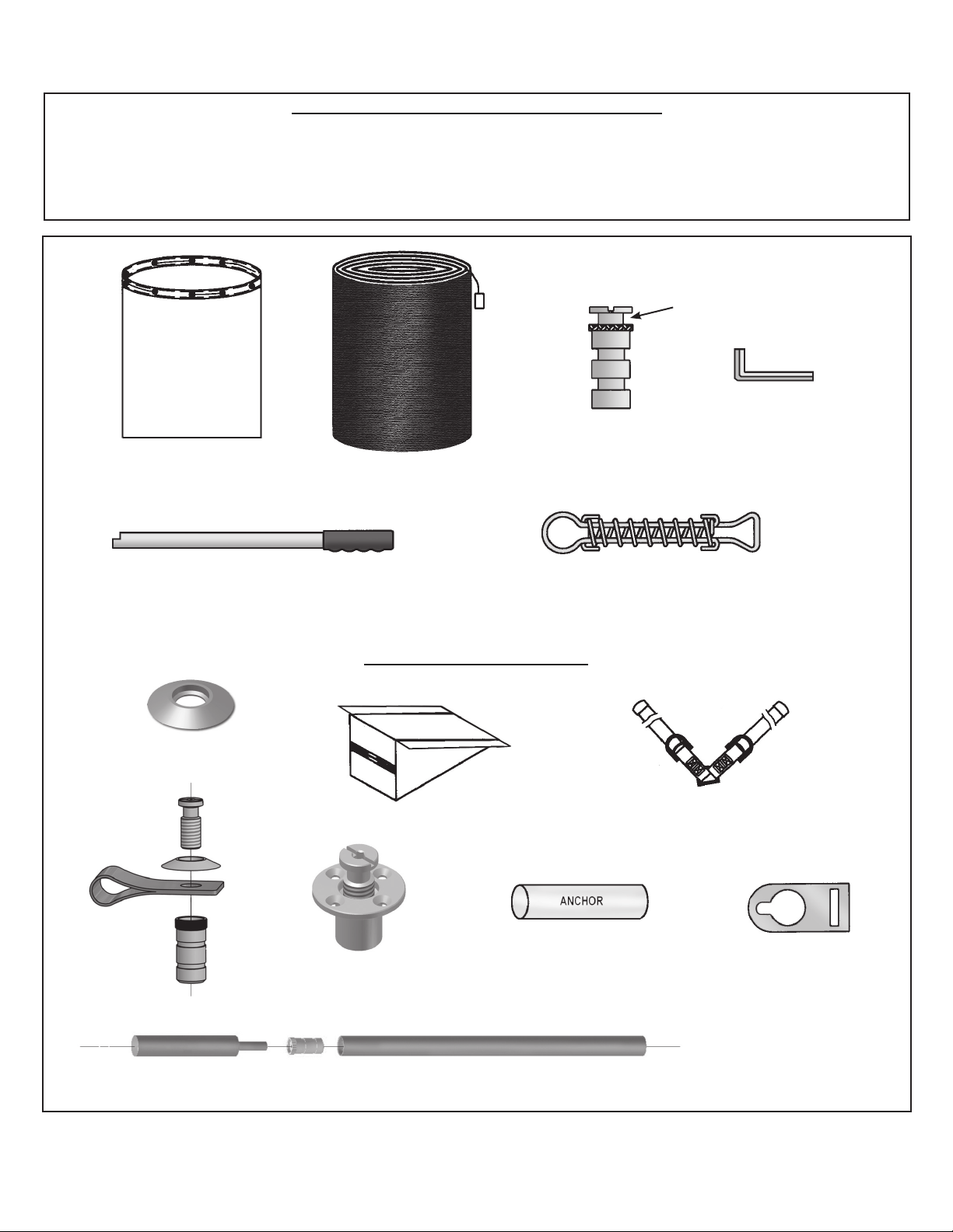
STEP 1:
TOOLS & HARDWARE
Tools Required For Installation
Rotary Hammer Drill Hammer 3/4” Masonry Bit
Block of wood Tape Measure 5 Gallon Buckets
Chalk Chalk Line Extension Cord (must be “GFCI rated)
OPEN
POOL COVER
STORAGE BAG
BRASS
ANCHOR
MESH POOL COVER
3/16” ALLEN
WRENCH
SPRING INSTALLATION/REMOVAL TOOL
Optional Hardware
BRASS FLANGE
STEP WEDGE
WOOD DECK
TYE CLIP ASSEMBLY
ANCHOR
STAINLESS STEEL
SPRING
DIVING BOARD
SPRING SKID COVER
HARNESS
STAINLESS STEEL
POOL COVER
ANCHOR TAB
ANCHOR
SETTING TOOL
Proper safety equipment should be used at all times to ensure a safe installation. We suggest a careful examination be made to determine safety equipment needed, such as hard hats, steel toe shoes, safety glasses and
other as required.
BRASS
ANCHOR
GROUND TUBE
5
Page 6

STEP 2:
1) It is best to have water at operating level to install pool cover. Do not lower water more than
15” below deck level.
2) Remove all handrails, ladders, etc.
3) Unfold cover onto deck. DO NOT DRAG THE COVER.
4) Position buckets (filled with water) around pool.
PREPARE POOL FOR INSTALLATION
SPA
DECK
BUNDLE
PLACED AT
END OF POOL
BUCKET
(TYPICAL)
STEP 3:
1) Place bundled cover as shown.
2) Unroll pool cover at end of pool as illustrated below. (Cross webs should be on bottom side.)
3) Position a water bucket on web strap at center cross web.
4) Once cover is unrolled, start unfolding cover towards opposite end and place water buckets on a
web strap across from each other. Continue doing this until pool cover has completely covered
pool.
NOTE: Do not place water buckets on cover, damage may occur. Place water buckets
only on web straps.
PLACING COVER OVER POOL
SPA
DECK
BUCKET
(TYP.)
COVER
DECK
SPA
UNFOLD
TOWARD THIS
END OF POOL
IMPORTANT NOTE:
Installation of pool cover must begin at
any areas with cut-outs or zero tolerance
areas (such as at cable-construction).
When there are several areas like this,
start at most complicated of these areas.
6
BUCKET ON
STRAP
Page 7

STEP 4: ALIGNING POOL COVER
1) Once cover is unfolded across pool, line up cutouts for ladders, slide legs, etc. and/or cable areas. Be
sure the cover aligns properly with these objects first. See important note on page 13.
2) Reposition cover to equal the overlap all around pool edge. Use buckets to keep cover taut.
3) If cable is needed, see Optional Cable Assembly Installation Instructions (pages 14 & 15).
Otherwise, proceed to STEP 5.
CABLE
COVER
DECK
SPA
STEP 5: ATTACHING STAINLESS STEEL SPRING
1) Attach springs to web straps around cover.
2) Thread the web strap through the flat end of the spring and then back through the double
“D” rings attached at the covers edge. See illustration below.
SPRING
WEB STRAP
COVER
“D” RINGS
APPROX. 1’-5”
7
Page 8
STEP 6: LOCATING/SETTING BRASS ANCHOR &
FASTENING SPRINGS
1) Brass anchors are placed approximately 1-5” from pool cover edge, (have cover as taut as
possible before marking for brass anchors.)
1a) Rectangular Pool Covers: Start with center strap of pool’s length (tag). See *NOTE
below. Mark for brass anchor location (use chalk). Drill hole and set anchor, see FIG. 1.
Attach end of spring to brass anchor, see Fig. 2A. Repeat on opposite end. Go
to center strap of the pool’s width and repeat the same procedure. Now work from center
straps (width and length) toward corners alternating side to side (do not begin with corner
straps). Once you have set brass anchors and fastened springs, go to corners and set
brass anchors. Brass anchors should be over 1” from 90º corner, see FIG. 3.
1b) Shaped Pool Covers: Start with center strap of pool’s length (tag). See *NOTE below.
Mark for brass anchor location (use chalk). Drill hole and set brass anchor, see FIG. 1.
Attach spring to brass anchor, see FIG. 2A. Repeat on opposite end with center strap. Go to
center strap of the pool width and repeat the same procedure. Now start working around your cover.
Remember to set brass anchor and fasten straps across from each other as you work around the
cover.
*NOTE: Before setting any brass anchors, check to see if there are any obstructions
such as diving boards, rocks, etc. at center web location. If there is obstruction at center web, start with nearest web on either side.
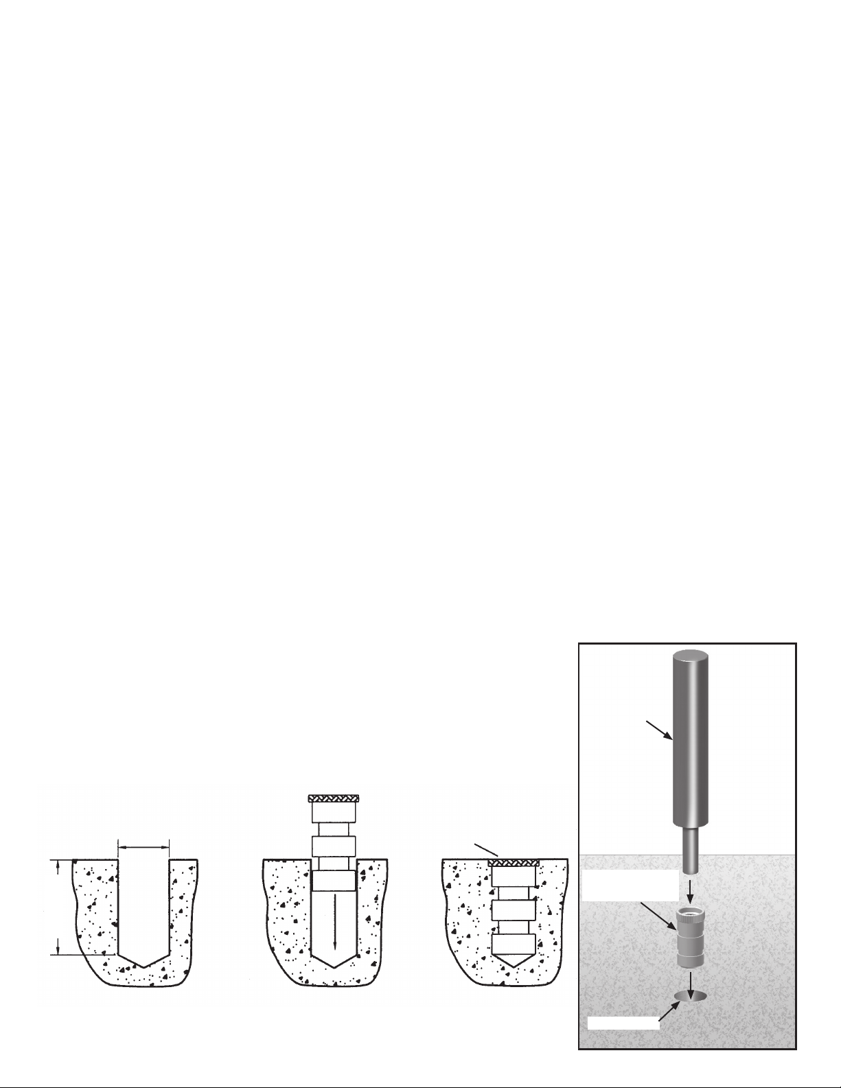
DRILLING HOLES FOR BRASS ANCHORS
1) Drill holes no more than the depth of the brass anchor (1 5/8”). **Do not over-ream the
diameter of the hole. If this does happen, apply a masonry anchor adhesive to the brass
anchor before setting into hole. (Note: clean hole out before setting brass anchor).
2) With screw removed, place brass anchor into hole. With a hammer and setting tool, firmly tap brass
anchor into hole.
3) Brass anchor should be flush with deck.
**NOTE: For best results, use a sharp masonry bit and a highspeed rotary hammer drill to reduce chipping. If chipping still
occurs, use flanges with brass anchors (available on request)
to cover these areas.
3/4”
SCREW
REMOVED
Setting Tool
Brass Anchor
(without screw)
8
1 5/8”
FIG. 1
Drilled hole
Page 9

INSTALLING
1) When fastening the springs, the brass anchor inserts should be in the open position (opened
approximately 1/2”). The end of the spring is approximately 1’-5” from the end of the pool cover
to allow for spring tensioning when securing to the brass anchor. Slide the spring onto the end of
the spring tool until it is approximately 6” up the end of the spring tool. Leverage the spring tool
onto the insert and push the spring down into position with your shoe (never use your hand).
With the spring over the insert, pull the spring tool out. If there is too much tension on the web
and spring, loosen the web strap and follow the fastening procedures again
SPRING
TOOL
INSERT
OPEN
POSITION
6”
APPROX.
INSTALLATION/REMOVAL OF SPRING
.
SPRING
WEB
STRAP
COVER
1/2”
APPROX.
REMOVAL
1) To remove, hold the spring tool so that the notch is facing away from the pool and insert it
into the spring which encircles the open brass anchor. Press down on the spring tool handle and
rotate it 180 degrees until the notch faces the pool. Tilt the tool slightly toward the cover to slide
the spring up the tool and release tension.
After releasing one side, the springs on the opposite side will be easily removed.
FIG. 2A
FIG. 2B
9
Page 10

INSTALLING BRASS ANCHORS AT CORNERS
90º
1”
1”
FIG. 3
90º
STEP 7: READJUST COVER
1) Once cover is anchored, re-adjust straps as needed. Cover should be very taut across the
pool. With proper tensioning, springs should be approximately half compressed.
UNTENSIONED
APPROXIMATELY HALF
TENSIONED
STEP 8: INSPECTION AND CLEAN-UP
1) After the cover has been installed, look for any area (besides that reinforcement attached to
the cover during manufacturing) that may need protective padding on the underneath side of
cover. On site padding may consist of carpeting, vinyl liner remnants, etc.
Complete the installation by sweeping any concrete dust and tucking the straps under the cover.
Deliver the door knob pack with warranty and user information to the homeowner.
CALL ANCHOR POOL COVER SALES @ 1-800-255-5552
TO CLARIFY INSTALLATION INSTRUCTION
10
QUESTIONS.
Page 11

STEP 9: STEP WEDGES
POOL COVER
w/ OVERLAP
POOL COVER SPRING
SNUGGED CLOSE TO
BOTTOM STEP WEDGE.
STEP 9A
WEDGES FOR
DESCENDING SIDE.
SPRINGS LOOSENED UNTIL STEP
WEDGES ARE IN PLACE
STEP WEDGES TUCKED UNDER EDGE
OF POOL COVER OVERLAP AND
CLIPPED AT OUTER FLAP.
1. Before tightening the pool cover anchors near the steps, tuck step wedges under the overlap edge of the
cover, as needed.
2. Pull the outer edge of the cover to the outside flap of the wedges and clip the flap to edge of the cover
using the fasteners provided.
3. Install the springs and anchors to tighten the cover.
4. Be sure that the last springs near the top and bottom steps are snugged up close to the wedge to secure
it firmly in place.
5. Step Wedges come in custom sizes measured on the horizontal dimension along the step. Custom sized
wedges will be made upon request.
CLIP FOR
STEP
WEDGES
11
Page 12

STEP 9B
COMPLETE STEP COVERING,
WITH WEDGES IN PLACE
AND SPRINGS INSTALLED TO
SECURE THE COVER.
SPRINGS
ATTACHED
TO BRASS
ANCHORS.
WEDGES
CLIPS
TYE CLIP
STEP 9C INSTALLING STEP WEDGES
FLAPS FOR
CLIPPING TO
COVER
ZIPPER FOR
STUFFING WITH
DUNNAGE
STEP WEDGE
TYE CLIP INSTALLATION
SPRING
ATTACHED
TO BRASS
ANCHOR
TYE CLIP
POOL
COVER
• Determine best
placement for Tye Clip
Assembly.
• Install Brass Anchor
butted up next to edge of
pool cover.
12
STEP WEDGE
STEP
WEDGE CLIP
BRASS POOL
COVER ANCHOR
• Assemble the Tye Clip
as shown in drawing to
the left.
• Catch pool cover
beneath the black or
white Poly Strip. (See
drawing to the left)
Page 13
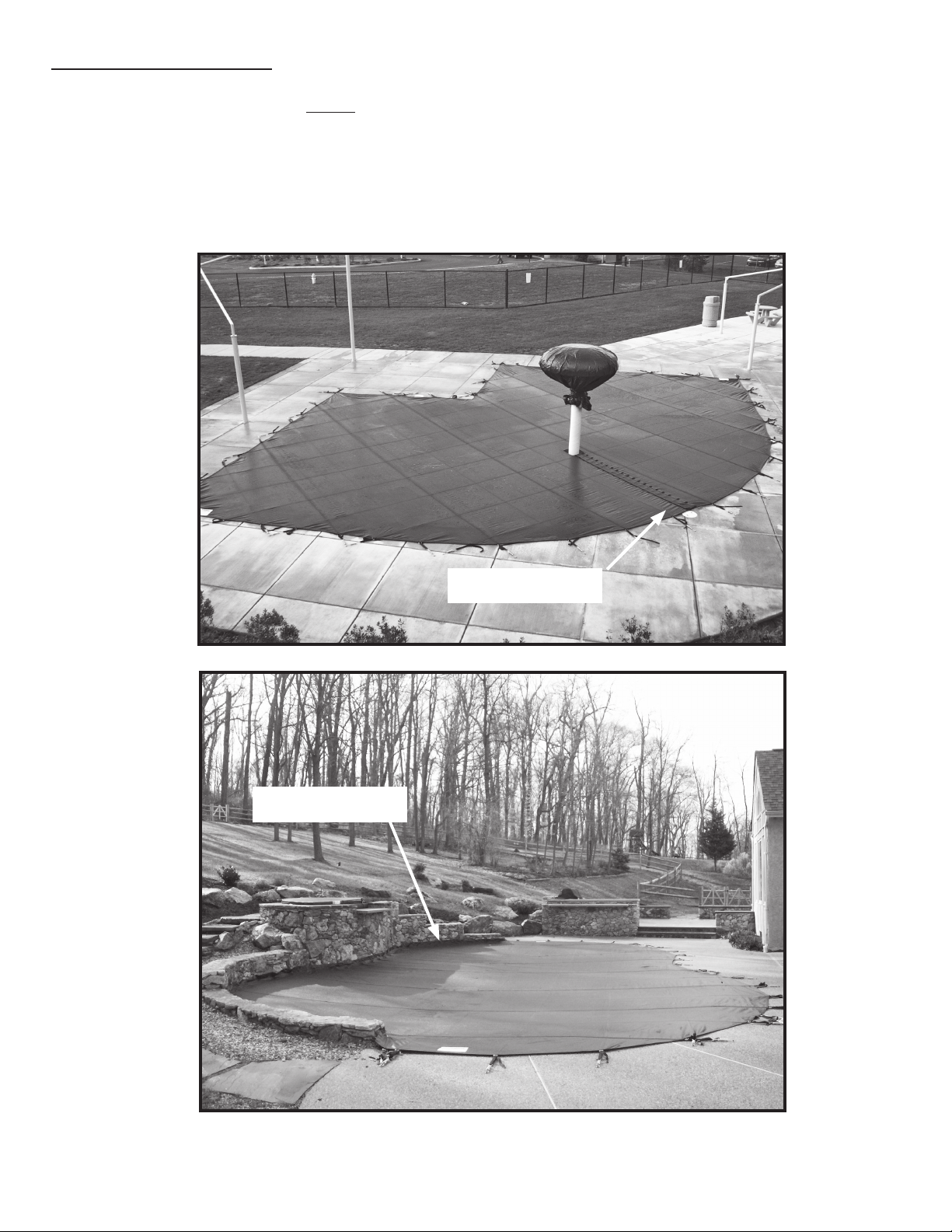
IMPORTANT NOTE:
Installation of pool cover must begin at any areas with cut-outs or zero tolerance
areas (such as at cable-construction). When there are several areas like this, start
at most complicated of these areas.
Start installation at
cable area
Start installation at
laced cutout
13
Page 14
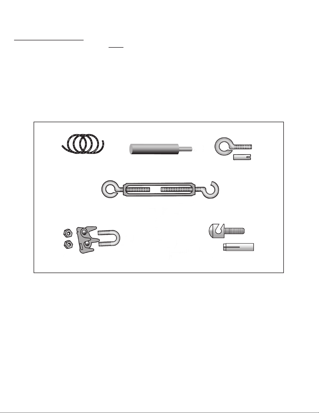
OPTIONAL CABLE ASSEMBLY INSTALLATION
IMPORTANT NOTES:
1. Installation of pool cover must begin at any areas with cut-outs or zero tolerance areas
(such as at cable-construction). When there are several areas like this, start at most
complicated of these areas.
2. This application of cable is for a standard straight wall installation. A custom cable
area may require special installation and hardware. If you have any questions call
your Anchor Representative to assist you.
Install cable hardware at the same level as the rest of the cover!
HARDWARE
3/16” STAINLESS
STEEL CABLE
CABLE CLAMP
1) Install 3/8” drop-in anchor with 3/8” eyebolt on one end of cable area. See FIG. 4
2) Install 3/8” drop-in anchors at the opposite end of the cable area and approximately 18” apart for the 3/8”
cable anchor bolts. When installing the cable anchor bolt to the cable area, align the hole in the anchor bolt in
the direction of the cable. see FIG. 5A. Run the cable through the in-line holes. see FIG. 5B. Run one end
of the cable through the cable anchor at one end of cable area and loop. Attach (2) cable clamps and tightly
secure cable, see FIG. 5A. Run other end of cable through eyebolt on turnbuckle, make loop and attach (1)
cable clamp for now. With turnbuckle fully extended out, attach hook end of turnbuckle to the eyebolt at the end
of the cable area. Loosen the (1) cable clamp and pull cable as taut as possible. Tighten (1) cable clamp and
add second cable clamp now. Be sure all cable clamps are tight to secure the cable. Rotate mid-section of turnbuckle to tighten cable further, see FIG. 5C.
SETTING TOOL
3/8” MACHINE THREADED
EYEBOLT AND DROP-IN
ANCHOR
TURNBUCKLE
3/8” SLOTTED CABLE ANCHOR
BOLT -DROP IN ANCHOR
3) Attach the snaps located under pool cover in cable area onto cable. See FIG. 5D.
14
Page 15

FIG. 4
Drilling/Setting of 3/8” Drop-in Anchors
EMBEDMENT
3/8” Drop-in
Drill Diameter - 1/2”
Minimum Depth - 1 7/8”
1) Drill a hole into base material to the depth of embedment (see information above) required. Do not over-drill
hole. Blow the hole clean of dust and other material. Insert the drop-in anchor into the hole and tap flush with
surface. Using setting tool, set drop-in anchor by driving the tool into the drop-in anchor until the shoulder of the
tool is seated against the drop-in anchor.
RAISED WALL
CABLE
ANCHOR
BOLT
SLOTTED CABLE
ANCHOR BOLT
CABLE
CLAMPS
CABLE
ANCHOR BOLT
APPROX. 18”
CABLE
CABLE
CABLE
CLAMPS
FIG. 5A
TURNBUCKLE
EYEBOLT
CABLE
FIG. 5C
ATTACH CABLE TO EYEBOLT ON TURNBUCKLE
COVER
EYEBOLT
END
TURNBUCKLE
EXTENDED
WEATHER FLAP
HOOK
END
FIG. 5B
RUNNING CABLE THROUGH
IN-LINE HOLES ON SLOTTED
CABLE ANCHOR BOLTS
SNAP
ATTACHING SNAP TO CABLE
Pool Cover Storage When Not In Use
Your pool cover is made from tough synthetic materials. Remove all hardware as it can cause damage not covered by warranty. Store the cover dry and cleaned off in a cool, dry place. Rodents, ants, and other pests are
known to eat pool covers if stored outdoors, on the garage floor or in a place where critters can get to it. Your
storage bag serves as a convenient method of keeping the cover contained for storage on shelf, hanging above
the floor, or elevated in the pool shed.
FIG. 5D
15
Page 16

EVANSVILLE, INDIANA
Thank you for purchasing an Anchor product. In return, we pledge Quality, Service and
Craftsmanship and are available for any questions you may have or assistance you may need.
PHONE NUMBER
812-867-2421
FAX NUMBER
812-867-1429
Anchor products are of superior design and operate best within the parameters of these
instructions. It is IMPERATIVE that the instructions be carefully read and COMPLETELY
FOLLOWED. Please read installation instructions before the installation or removal of this
product. Installation instructions are also available at: www.anchorinc.com.
CAUTION
1. For each installation, the installer is solely responsible for evaluating the site for the proper
securing methods and fasteners to be used. Standard fasteners furnished may be inadequate, site
unseen by Anchor, thus requiring additional or alternate method of fastening.
2. Inasmuch as the weather is unpredictable, good judgment and common sense must be
incorporated within installation guidelines. Proper safety equipment should be used at all times to
insure a safe installation and removal. We suggest a careful evaluation be made to determine safety
equipment needed, such as hard hats, steel-toe shoes, safety glasses and other as required.
3. Anchor stands behind its products in accordance with its standard Terms and Conditions of sale.
A copy of our Terms and Conditions of Sale can be obtained by contacting Anchor at the telephone
number and/or address on this document.
1-800-255-5552
1100 Burch Dr. • P.O. Box 3477 • Evansville, IN 47733 U.S.A. • Ph. (812)867-2421 • Fax (812)867-1429
E-mail: custdiv@anchorinc.com • www.anchorinc.com
29.0 7-31-02
 Loading...