

Page 1
CouncilMAN Conference System Owners Manual
A Message from the President
Congratulations on purchasing an Anchor Audio sound system, the choice of thousands
of satisfied customers including the White House, prestigious universities, school
districts nationwide, police and fire departments, and all branches of the U.S. Military.
Our products are made of the finest materials and built with pride in the U.S.
We’ve incorporated the latest technology into your sound system yet kept it simple to
use. Just take a few minutes to review this manual to ensure the maximum enjoyment
of your Anchor system. Or, you can view a demonstration video complete with a trouble
shooting section at www.anchoraudio.com.
Feel free to call our friendly customer support staff at 1-800-ANCHOR1
with any questions. We love to hear from our customers.
Janet Jacobs, President
on behalf of all Anchor employees
CONTENTS
GETTING STARTED .................................................................................................................. 1
COUNCILMAN OVERVIEW / BASIC OPERATION / OPERATING WIRELESS MIC ............................. 2
IMPORTANT SAFETY INSTRUCTIONS ................................................................................... 3 - 4
TECHNICAL SPECS ..................................................................................................................5
MADE IN USA
MADE IN USA
SIX YEAR WARRANTY
SIX YEAR WARRANTY
GETTING STARTED
Please check your new unit carefully for any
damage which may have occurred during shipment.
Each Anchor product is carefully inspected at the
factory and packed in specially designed boxes for
safe transport.
Notify the freight carrier immediately of any damage
to the shipping box or product. Repack the unit
in the original box and wait for inspection by the
carrier’s claim agent. Notify your dealer of the
pending freight claim.
NOTE: All damage claims must be made with freight carrier!
RETURNING SYSTEMS FOR SERVICE
OR REPAIR
For service or repair, please contact the dealer
you purchased your system from or visit
www.AnchorAudio.com to fill out an
RA
(Return Authorization)
still under warranty, you will receive an RA Number
with instructions to follow. All shipments to Anchor
Audio must include an RA number and must be
shipped prepaid. C.O.D. shipments and shipments
without an RA number will be refused and returned
at your expense.
IMPORTANT: Save the shipping box & packing materials,
they were specially designed to ship your unit!
The CouncilMAN Conference system comes
with a two year warranty.
form. If your system is
For System Setup & Operation Videos Visit Our Website: www.anchoraudio.com
1
Page 2
CouncilMAN Conference System Owners Manual
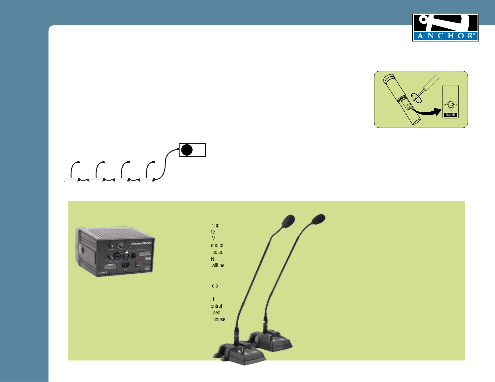
WHAT IS COUNCILMAN?
CouncilMAN is a wired conference system that’s simple to set up and
easy to use. The main system components include:
• CHM-100 Chairman base
• DEL-100 Delegate bases
• Gooseneck microphones
• AN-100CM+ speaker/power console
Station to station connection is made using standard microphone
cable with 3-pin XLR connectors. The AN-100CM+ provides power
to each microphone base. Up to 16 microphone bases can be used
with the AN-100CM+.
AN-100CM
Delegate 1 Delegate 2 Chairman Delegate 3
A typical four base conference system is illustrated here
BASIC SYSTEM OPERATION
1. Place a microphone into each base
2. Daisy-chain all the microphone bases and the
AN-100CM+ powered speaker. The speaker must be
near a power outlet – plug in the AC cord.
3. Set the AN-100CM+ power switch to ON and volume
knob to 12 o’clock
4. Push the microphone base MIC ON/OFF buttons once
to talk, press again to turn off. When a microphone is
live, its talk switch will be illuminated.
5. Adjust the microphone so it is near the mouth
6. Set volume controls on each base
IMPORTANT: When the conference system is powered up, all
microphones wake up in the OFF condition.
MADE IN USA
SIX YEAR WARRANTY
OPERATING THE WIRELESS MICROPHONE
WITH AN-100CMU1+
CHANNEL SELECTION - HANDHELD TRANSMITTER
1. Unscrew battery cover on bottom of microphone
2. Set the CHANNEL SELECTOR dial to match
the channel setting of your receiver on
the AN-100CMU1+
3. Replace the battery cover
4. Adjust volume on AN-100CMU1+ and begin
speaking
AN-100CM+ Powered Speaker
The AN-100CM+ can power up
to ten chairman and delegate
microphones. The AN-100CM+
can be connected to either end of
the daisy chain. When connected
at an end, only one of the AN-
100CM+’s XLR connectors will be
occupied.
The AN-100CM+ also includes a 3.5mm standard Line In allowing audio
from other sources to be played through the system. A ¼” Line Out is
provided for connection to a recorder or other device. The power switch,
volume control knob and all input and output connectors are on the control
panel on the rear of the speaker. The balanced XLR Line Out can be used
to connect another Anchor system for larger crowd coverage or to the house
system.
For System Setup & Operation Videos Visit Our Website: www.anchoraudio.com
CHM-100 and DEL-100 Microphone Bases
The microphone bases have a 3-pin XLR Input Jack and a 3-pin
XLR Output Jack. Daisy chain the microphones in any order with
the AN-100CM+ using the EX-4M (4 foot mic cable) or EX-25M
(25 foot mic cable). Each base has a 3-pin XLR Female electret
microphone jack
CHM-100 Chairman Controls:
MIC ON/OFF – push once to Talk and push again to mute, LED lit
when mic is live
Rotary Volume – adjustable volume for each user’s voice level
Mute Others – press for several seconds to Mute All delegates in
the conference system or the wireless module
DEL-100 Delegate Controls:
MIC ON/OFF – push once to Talk and push again to mute, LED lit
when mic is live. If the Chairman mutes all, the Talk/On/Off button
must be pressed to have the mic go live.
Rotary Volume – adjustable volume for each user’s voice level
2
Page 3

CouncilMAN Conference System Owners Manual
General Warning or Caution
MADE IN USA
Electrical Shock Symbol
Figure Protective Conductor
Terminal Symbol
Figure Alternating Voltage
Symbol
Figure Fuse Symbol
Figure On Symbol
O
Figure Off Symbol
The Exclamation Symbol in the figure above appears in Warning and Caution
tables throughout this document. This symbol designates an area where
personal injury or damage to the equipment is possible.
Electric Shock
The Electrical Shock Symbol in the figure above appears throughout this manual.
This symbol indicates a hazard arising from dangerous voltage. Any mishandling
could result in irreparable damage to the equipment, and personal injury or
death.
Protective Conductor Terminal
The Electrical Shock Symbol in the figure above appears throughout this manual.
This symbol indicates a hazard arising from dangerous voltage. Any mishandling
could result in irreparable damage to the equipment, and personal injury or
death.
European Union CE Mark European Union CE Mark
The presence of the CE Mark on Anchor equipment means that it has been
designed, tested and certified as complying with all applicable European Union
(CE) regulations and recommendations.
Alternating voltage symbol
The presence of the CE Mark on Anchor equipment means that it has been
designed, tested and certified as complying with all applicable European Union
(CE) regulations and recommendations.
Fuses
The fuse symbol in the figure above identifies the fuse location on the Anchor
System. (Not required if not user replaceable)
On Symbol
The On Symbol in the figure above represents a power switch position on the
Anchor System. This symbol represents a Power On condition.
Off Symbol
The Off Symbol in the figure above represents a power switch position on the
Anchor System. This symbol represents a Power Off condition.
For System Setup & Operation Videos Visit Our Website: www.anchoraudio.com
SIX YEAR WARRANTY
Waste Electrical and Electronic Equipment (WEEE)
This symbol on the product or on its packaging indicates that this product
must not be disposed of with regular waste. Instead, it is the user responsibility
to dispose of waste equipment according to the local laws. The separate
collection and recycling of the waste equipment at the time of disposal will help
Figure WEEE Directive Symbol
to conserve natural resources and ensure that it is recycled in a manner that
protects human health and the environment. For information about where the
user can drop off the waste equipment for recycling, please contact your local
Anchor representative. See Section for instructions on how to disassemble the
equipment for recycling purposes.
Inspection for Damage
The Model Councilman is carefully packaged at the factory to minimize the
possibility of damage during shipping. Inspect the box for external signs of
damage or mishandling. Inspect the contents for damage. If there is visible
damage to the instrument upon receipt, inform the shipping company and
Anchor Inc. immediately.
Inspection for Damage
Do not attempt to operate this equipment if there is evidence
of shipping damage or you suspect the unit is damaged.
Damaged equipment may present additional hazards to you.
Contact Anchor technical support for advice before attempting
to plug in and operate damaged equipment.
Electrical Requirements
Before attempting to power up the unit for the first time, the following
precautions must be followed:
WARNING
To avoid electric shock, connect the instrument to properly
earth-grounded, 3-prong receptacles only. Failure to observe
this precaution can result in severe injury.
Have a qualified electrician verify the wall socket that will be used is properly polarized and properly
grounded.
Warning: To reduce the risk of fire or electric shock, do not expose this apparatus to rain or moisture,
apparatus shall not be exposed to dripping or splashing and no objects filled with liquids, such as vases,
shall be placed on the apparatus.
The apparatus connected to a main socket outlet with a protective earthing connection. For Nordic
markings refer to copy of marking label.
The plug in the power cord is the AC mains disconnected device and must remain readily operable. –
minimum distances around the apparatus for sufficient ventilation; the ventilation should not be impeded
by covering the ventilation openings with items, such as newspapers, table-cloths, curtains, etc.; no
naked flame sources, such as lighted candles, should be placed on the apparatus.
-Equipment may be located above or below this apparatus, but some equipment (like large amplifiers)
may cause an unacceptable amount of hum or may generate too much heat and degrade the
performance of this apparatus.
3
Page 4

CouncilMAN Conference System Owners Manual
Important Safety Instructions
1) Read Instructions – All the safety and operation instructions should be read before the
product is operated.
2) Retain Instructions – The safety and operating instructions should be retained for future
reference.
3) Heed Warnings- All warnings on the product and in the operating instructions should be
adhered to.
4) Follow Instructions – All operating and use instructions should be followed.
5) Cleaning – Unplug this product from the wall outlet before cleaning. Do not use liquid
cleaners or aerosol cleaners. Use a damp cloth for cleaning.
Exception: A product that is meant for uninterrupted service and that for some specific
reason, such as the possibility of the loss of an authorization code for the CATV converter,
is not intended to be unplugged by the user for cleaning or any other purpose, may
exclude the reference to unplugging the product in the cleaning description otherwise in
above 5).
6) Attachments – Do not use attachments not recommended by the product manufacturer
as they may cause hazards.
7) Water and Moisture – Do not use this product near water – for example, near a bath tub,
wash bowl, kitchen sink, or laundry tub; in a wet basement; or near a swimming pool;
and the like.
8) Accessories – Do not place this product on an unstable cart, stand, tripod, bracket, or
table. The product may fall, causing serious injury to a child or adult, and serious damage
to the product. Use only with a cart, stand, tripod, bracket, or table recommended by the
manufacturer, or sold with the product. Any mounting of the product should follow the
manufacturer’s instructions, and should use a mounting accessory recommended by the
manufacturer.
9) A product and cart combination should be moved with care. Quick stop, excessive force,
and uneven surfaces may cause the product and cart combination to overturn.
10) Ventilation – Slots and openings in the cabinet are provided for ventilation and to ensure
reliable operation of the product and to protect it from overheating, and these openings
must not be blocked or covered. The openings should never be blocked by placing the
product on a bed, sofa, rug, or other similar surface. This product should not be placed in
a build-in installation such as a bookcase or rack unless proper ventilation is provided or
the manufacturer’s instructions have been adhered to.
11) Power Sources – This product should be operated only from the type of power source
indicated on the marking label. If you are not sure of the type of power supply to your
home, consult your product dealer or local power company. For products intended to
operate from battery power, or other sources, refer to the operating instructions.
12) Grounding or Polarization – This product may be equipped with a polarized alternatingcurrent line plug (a plug having one blade wider than the other). This plug will fit into
the power outlet only one way. This is a safety feature. IF you are unable to insert the
plug fully into the outlet, try reversing the plug. If the plug should still fail to fit, contact
your electrician to replace your obsolete outlet. Do not defeat the safety purpose of the
polarized plug.
13) Power-Cord Protection – Power-supply cords should be routed so that they are not likely
to be walked on or pinched by items placed upon or against them, paying particular
attention to cords at plugs, convenience receptacles, and the point where they exit from
the product.
14) Protective Attachment Plug – The product is equipped with an attachment plug having
overload protection. This is a safety feature. See Instruction Manual for replacement or
resetting of protective device. If replacement of the plug is required, be sure the service
technician has used a replacement plug specified by the manufacturer that has the same
overload protection as the original plug.
For System Setup & Operation Videos Visit Our Website: www.anchoraudio.com
15) Outdoor Antenna Grounding – If an outside antenna or cable system is connected to
16) Lightning – For added protection this product during lightning storm, or when it is left
17) Power Lines – An outside antenna system should not be located in the vicinity of
18) Overloading – Do not overload wall outlets, extension cords, or integral convenience
19) Object and Liquid Entry – Never push objects of any kind into this product through
20) Servicing – Do not attempt to service this product yourself as opening or removing
21) Damage Requiring Service – Unplug this product from the wall outlet and refer servicing
a. When the power-supply cord or plug is damaged.
b. If liquid has been spilled, or objects have fallen into the product.
c. If the product has been exposed to rain or water.
d. If the product does not operate normally by following the operating
e. If the product has been dropped or damaged in any way.
f. When the product exhibits a distinct change in performance – this indicates a
22) Replacement Parts – When replacement parts are required, be sure the service
23) Safety Check – Upon completion of any service or repairs to this product, ask the service
24) Wall or Ceiling Mounting – The product should be mounted to a wall or ceiling only as
25 Heat – The product should be situated away from heat sources such as radiators, heat
MADE IN USA
SIX YEAR WARRANTY
the product, be sure the antenna or cable system is grounded so as to provide some
protection against voltage surges and built-up static charges. Article 810 of the National
Electrical Code, ANSI/NFPA 70, provides information with regard to proper grounding of
the mast and supporting structure grounding of the lead in wire to an antenna discharge
unit, size of grounding conductors, location of antenna-discharge unit, connection of
grounding electrodes, and requirements for the grounding electrode. See Figure A.
unattended and unused for long periods of time, unplug it from the wall outlet and
disconnect the antenna or cable system. This will prevent damage to the product due to
lightning and power-line surges.
overhead power lines or other electric light or power circuits, or where it can fall into
such power lines or circuits. When installing an outside antenna system, extreme care
should be taken to keep from touching such power lines or circuits as contact with them
might be fatal.
receptacles as this can result in a risk of fire or electric shock.
openings as they may touch dangerous voltage points or short-out parts that could result
in a fire or electric shock. Never spill liquid of any kind on the product.
covers may expose you to dangerous voltage or other hazards. Refer all servicing to
qualified service personnel.
to qualified service personnel under the following conditions:
instructions. Adjust only those controls that are covered by the operating
instructions as an improper adjustment of other controls may result in damage
and will often require extensive work by a qualified technician to restore the
product to its normal operation.
need for service.
technician has used replacement parts specified by the manufacturer or have the same
characteristics as the original part. Unauthorized substitutions may result in fire, electric
shock, or other hazards.
technician to perform safety checks to determine that the product is in proper operation
condition.
recommended by the manufacturer.
registers, stoves, or other products (including amplifiers) that produce heat.
4
Page 5

CouncilMAN Conference System Owners Manual
MADE IN USA
COUNCILMAN TECHNICAL SPECIFICATIONS
AN-100CM+ Console Speaker
Rated Power Output 30 watts
Max SPL @ Rated Power 103 dB @ 1 meter
Frequency Response 65 Hz – 18 kHz ± 3 dB
Speaker Type 4.5” woofer, 10 mm dome
tweeter Magnetically
Shielded
AC Power Reqs. 100 – 240 VAC, 50/60 Hz
Fuse Rating T 1.0A / 250V
(internally mounted)
Export Model T 0.5A / 250V
(internally mounted)
CHM-100/DEL-100 Microphone Base
Power Requirement +22 VDC @ 60 mA from
pin 2 of daisy chain
Output Impedence >10k Ω
Phantom Power 18 V
Dimensions (HWD) 5.8” x 6.5” x 1.75”
(14.73 x 16.51 x 4.45 cm)
Weight 0.90 lbs / .41 Kg
Daisy Chain In/Out Male and Female 3 pin XLR
CHM-100 Controls Push to Talk, Volume and
Mute Others
DEL-100 Controls Push to Talk and Volume
Warranty 2 years
SIX YEAR WARRANTY
Line In 3.5mm
Line Out Lo-Z, buffered, XLR and
1/4” Balanced
Line Output Level -20 dBV (100 mVrms)
Enclosure Material ABS Plastic
Dimensions (HWD) 5.25” x 8.4” x 9”
(13 x 21 x 23 cm)
Weight 8.5 lbs / 3.8 Kg
Warranty 6 years
LM-618 Gooseneck Microphone
Pickup Pattern Cardioid
Type Back Electret Condenser
Phantom Power 9 - 52 Volts DC
Impedence 200 Ω @ 1kHz
Response 80 Hz - 17 kHz ±3dB
Sensitivity -56 dB @ 1 kHz open circuit
(0 dB = 1 V/ubar)
Dimension 18.75” from mic tip to XLR
top, 2 flex sections
Microphone 0.54” O.D.
Warranty 2 years
(Specifications Subject to Change Without Notice)
ANCHOR AUDIO CUSTOMER SERVICE
For System Setup & Operation Videos Visit Our Website: www.anchoraudio.com
800.262.4671
FOR ADDITIONAL INFORMATION
visit www.anchoraudio.com
5
 Loading...