

Page 1
Beacon® Sound System Owners Manual
A Message from the President
Congratulations on purchasing an Anchor Audio sound system, the choice of thousands
of satisfied customers including the White House, prestigious universities, school
districts nationwide, police and fire departments, and all branches of the U.S. Military.
Our products are made of the finest materials and built with pride in the U.S.
We’ve incorporated the latest technology into your sound system yet kept it simple to
use. Just take a few minutes to review this manual to ensure the maximum enjoyment
of your Anchor system. Or, you can view a demonstration video complete with a trouble
shooting section at www.anchoraudio.com.
Feel free to call our friendly customer support staff at 1-800-ANCHOR1
with any questions. We love to hear from our customers.
Janet Jacobs, President
on behalf of all Anchor employees
CONTENTS
GETTING STARTED .................................................................................................................. 1
BASIC SYSTEM OPERATION / LINE ARRAY TOWER / BACK PANEL .............................................. 2
TRAVEL DOLLY / CONTROLLING FEEDBACK ............................................................................. 3
USING THE BUILT-IN MP3 / OPERATING THE BUILT-IN UHF WIRELESS RECEIVER ......................... 4
OPERATING THE WIRELESS MICROPHONE/TRANSMITTER ......................................................... 5
CARING FOR YOUR BATTERY ................................................................................................... 6
iMPORTANT SAFETY INSTRUCTIONS ........................................................................................ 7
HAVING TROUBLE WITH YOUR SOUND SYSTEM? / TECHNICAL SPECS ....................................... 8
MADE IN USA
MADE IN USA
SIX YEAR WARRANTY
SIX YEAR WARRANTY
GETTING STARTED
Please check your new unit carefully for any
damage which may have occurred during shipment.
Each Anchor product is carefully inspected at the
factory and packed in specially designed boxes for
safe transport.
Notify the freight carrier immediately of any damage
to the shipping box or product. Repack the unit
in the original box and wait for inspection by the
carrier’s claim agent. Notify your dealer of the
pending freight claim.
NOTE: All damage claims must be made with freight carrier!
RETURNING SYSTEMS FOR SERVICE
OR REPAIR
For service or repair, please contact the dealer
you purchased your system from or visit
www.AnchorAudio.com to fill out an
RA
(Return Authorization)
still under warranty, you will receive an RA Number
with instructions to follow. All shipments to Anchor
Audio must include an RA number and must be
shipped prepaid. C.O.D. shipments and shipments
without an RA number will be refused and returned
at your expense.
IMPORTANT: Save the shipping box & packing materials,
they were specially designed to ship your unit!
The Beacon Sound System comes with a six year warranty,
and all Anchor Audio batteries, CD/MP3, and wireless come
with a two year warranty.
form. If your system is
For System Setup & Operation Videos Visit Our Website: www.anchoraudio.com
1
Page 2
Beacon® Sound System Owners Manual
BASIC SYSTEM OPERATION
NOTE: Fully Charge Batteries Before First Use!
1. Remove Travel Dolly
(below)
2. Set all Input Levels to minimum & Tone Controls to flat
(middle)
setting
3. Plug wired microphone into the MIC 1 or MIC 2 jacks
and/or any audio source into the LINE-IN jacks
4. Switch POWER to ON, Power ON LED will light
5. Slowly increase Level Controls for active Input Jacks
to desired volume
6. Adjust Tone Controls for desired sound quality
IMPORTANT: Make all connections with shielded cables to avoid
hum, buzzing or interference.
OPENING BEACON LINE ARRAY
1. Open Array latches
2. Grasp handle and remove Array from base
3. Turn Array over and place on top of base
4. Close Array latches
5. Slowly flip Array Tower up until locked
securely into place
IMPORTANT: Latches MUST be locked and grill MUST
face forward for system to work!
CLOSING BEACON LINE ARRAY
1. Turn POWER to OFF
2. Fold Array in half (apply slight pressure)
3. Open latches and remove folded Array
4. Turn Array over grasp handle and slide into base
5. Close Array latches
(page 3)
and open Line Array
combined output of all active system inputs.
Balanced XLR – low impedance, for balanced mic,
Unbalanced 1/4” – high impedance, for unbalanced
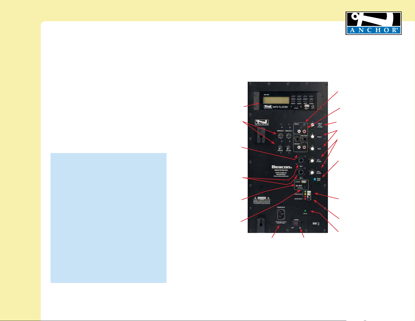
BACK PANEL OF BEA-7500MU2
MP3 PLAYER
(see page 4)
WIRELESS RECEIVERS
(see page 4)
LINE OUT – OUTPUT JACK
Balanced 1/4” & Dual RCA provide a
Record your presentation or connnect to
another powered sound system.
UNIVERSAL MIC – INPUT JACKS
powers condenser-type mics.
mics, no phantom power.
USB DC OUT -12V 500 mA
To charge/power external device
- 5V 500 mA
DC OUT
To charge/power external device
AC POWER CORD INLET
MADE IN USA
SIX YEAR WARRANTY
LINE IN – INPUT JACKS
The 1/8 (3.5mm) jack is used to hook
up a portable CD player, iPod, laptop
or other external audio source.
Dual RCA unbalanced inputs can
be used for daisy-chaining together
multiple Beacon speakers.
LINE IN LEVEL CONTROL
TONE CONTROLS – BASS/TREBLE
MICROPHONE LEVEL CONTROLS
VOICE OVER BUTTON
Reduce Line and CD Input levels by 12dB
when using microphones allowing speakers
to be heard over background music.
ON = Button In OFF = Button Out
CHARGE STATUS LEDS
Green - Charge complete
Amber - Charge nearly complete
Red - Charging has begun
Battery Empty LED
Red - charge battery immediately
Power On LED
Green - power on
POWER SWITCH
For System Setup & Operation Videos Visit Our Website: www.anchoraudio.com
2
Page 3
Beacon® Sound System Owners Manual
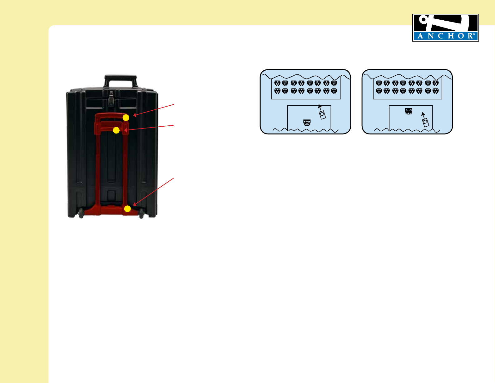
RETRACTABLE HANDLE
(CLOSED)
TOP BRACKET
BOTTOM BRACKET
MADE IN USA
SIX YEAR WARRANTY
CORRECT SYSTEM PLACEMENT WRONG SYSTEM PLACEMENT
CONTROLLING FEEDBACK
Feedback, a howling noise or shrill sound, is self-generated by the sound system. It’s caused by
a microphone picking up the sound coming from the speaker and then re-amplifying it. Once a
feedback loop starts, it continues until the system is adjusted.
FEEDBACK CAUSES
• Microphone too close, pointing towards
or in front of speaker
• Volume setting is too loud for room
• Sound reflecting off hard surfaces
AVOIDING & ELIMINATING FEEDBACK
• Point microphone in a different direction
• Keep microphone away from the speaker
• Place speaker in FRONT of the microphone
• Reduce the sound system volume levels
CAUTION: Feedback can damage your equipment & may be hazardous to hearing.
For System Setup & Operation Videos Visit Our Website: www.anchoraudio.com
3
Page 4

Beacon® Sound System Owners Manual
MADE IN USA
USING THE BUILT-IN MP3 PLAYER
Your MP3 player supports WMA and WAV files as well as
MP3. Input slots for play are USB, SD card slot and AUX
port for other music player devices.
Insert your memory card or USB stick and turn on the
MP3 POWER. Push MODE button until your device is displayed. The auxilliary port becomes active when 3.5mm
cable is inserted.
Anchor Audio UHF wireless is a 16 channel, diversity wireless system that receives signals with two independent antennae. With diversity
wireless the receiver processes the stronger signal, effectively minimizing dropouts and interference from other transmitting sources. The
antennae are mounted internally so there are no obstructions or risk of damage.
CHANNEL SELECTION - BUILT-IN RECEIVER
Select a channel, set the built-in receiver & microphone transmitter
to that channel before using your wireless system.
1. Choose any available wireless channel from 1 thru 16
(see page 5 for transmitter instructions)
2. Set the Wireless Channel Selection Knob to the channel you
choose in step 1
The LCD displays functions as used:
POWER: press once for ON or OFF
MODE: displays mode of operation
MUTE: press once for mute ON and again to
mute OFF
RPT: press and release to repeat song
TRACK+: press and release to next track
TRACK-: press and release for previous track
ALBUM+: press and release for next album or hold and
release until correct album is found
ALBUM-: press and release for previous album or hold
and release until correct album is found
DIVERSITY WIRELESS BY ANCHOR AUDIO
WIRELESS 1 CHANNEL
SELECTION
WIRELESS 1 RX
INDICATOR LIGHTS
SIX YEAR WARRANTY
EXTERNAL ACCESSORY
VOLUME CONTROL
WIRELESS 2 CHANNEL
SELECTION
WIRELESS 2 RX
INDICATOR LIGHTS
If you have two wireless receivers repeat above for the second receiver.
Remember, each receiver/transmitter pair must be set to different
channels to avoid interference.
NOTE: Ongoing wireless interference? The frequency you selected may be in use by other systems in the area!
Change channels until you find a clear frequency!
For System Setup & Operation Videos Visit Our Website: www.anchoraudio.com
WIRELESS 1
VOLUME CONTROL
WIRELESS 2
VOLUME CONTROL
4
Page 5

Beacon® Sound System Owners Manual
OPERATING THE WIRELESS MICROPHONE/TRANSMITTER
MADE IN USA
SIX YEAR WARRANTY
CHANNEL SELECTION - HANDHELD TRANSMITTER
1. Unscrew battery cover on bottom of microphone
2. Set the CHANNEL SELECTOR dial to match the channel setting
of your receiver
3. Replace battery cover and tighten firmly
NOTE: When using dual wireless, each microphone must be set to a different channel!
USING YOUR WIRELESS MICROPHONES
After you have set the transmitter channel (see above) you are ready to use your wireless microphone:
1. Body-pack transmitter users must insert
the mic plug into the transmitter jack marked
MIC
2. Push the transmitter power button for two seconds until ON (The red LED will stay on when
the mic is turned on. If the red LED flashes, the
battery is low)
3. Turn the Beacon power switch to ON
4. The RX indicators will light
will light at a time)
being transmitted and received
when the wireless signal is
CHANNEL SELECTION - BODY-PACK TRANSMITTER
1. The channel selection dial is located on the side of the transmitter
2. Set the CHANNEL selection dial to match the channel setting of the receiver
(only one indicator
CAUTION: Harmful feedback may occur when walking in front of a sound system or speaker with a wireless microphone. Always point microphone away from speakers!
REPLACE BATTERY - HANDHELD TRANSMITTER
1. Unscrew battery cover on bottom of microphone
2. Replace old batteries with two fresh size ‘AA’
alkaline batteries
3. Replace battery cover and tighten firmly
NOTE: Transmitter power must be OFF when changing batteries!
For System Setup & Operation Videos Visit Our Website: www.anchoraudio.com
REPLACE BATTERY - BODY-PACK TRANSMITTER
1. Slide open battery cover on front of transmitter
2. Replace old batteries with two fresh size ‘AA’
alkaline batteries
3. Replace battery cover by sliding firmly into place
5
Page 6

Beacon® Sound System Owners Manual
MADE IN USA
SIX YEAR WARRANTY
BATTERY REPLACEMENT
The batteries must be replaced every 2 – 3 years depending on
usage over time. Call Anchor Audio at 800.262.4671 to order
batteries.
To replace your batteries you will need a Phillips screwdriver and
follow these procedures:
1. Be sure the power switch is in the OFF position
2. Remove the screws in the lower cover panel of
the Beacon
3. Gently slide the cover panel with the battery tray out of
the case
4. Unclip each battery connection cable and remove the
batteries from the tray
5. Connect each new battery to the connection cable, attach
plate to the tray and slide the tray into the Beacon
6 Replace each screw in the cover panel
SYSTEM STORAGE & BATTERIES
Fully charge batteries before storage. For extended periods of
storage either leave system plugged into an AC outlet or charge
the system at least once each month for a minimum of 24 hours.
BUILT-IN BATTERY MAINTENANCE
To preserve battery life the built-in batteries MUST be FULLY
charged before the first use. Regardless of length of operation,
it is recommended that batteries be fully charged as soon as
possible after each use.
AC OPERATION & BATTERY CHARGING
Beacon Sound Systems include an automatic charging system
designed to properly charge and maintain the systems built-in
batteries. To charge batteries plug the system into an AC outlet
and operate as normal while built-in batteries are charging.
The CHARGE STATUS LED will light when charging. Bright red
indicates charge process has begun. Amber indicates the charge
process is almost complete, and green indicates full battery. It
takes approximately 7 hours to charge the completely drained
Beacon batteries.
BATTERY SERVICE TIME
Fully charged batteries will yield approximately 6 – 8 hours of
continuous music at medium volume level
volume or longer for speech only)
depending on control settings and use of accessories.
. However, service times vary
(2 – 4 hours at full
Waste electrical and electronic products must not be disposed
of with household waste. Please recycle where facilities exist.
Check with your Local Authority or Retailer for recycling advice.
For System Setup & Operation Videos Visit Our Website: www.anchoraudio.com
BATTERY COMPARTMENT
NOTE: System Can Be Used During Charging!
6
Page 7

Beacon® Sound System Owners Manual
Important Safety Instructions
1) Read Instructions – All the safety and operation instructions should be read before the
product is operated.
2) Retain Instructions – The safety and operating instructions should be retained for future
reference.
3) Heed Warnings- All warnings on the product and in the operating instructions should be
adhered to.
4) Follow Instructions – All operating and use instructions should be followed.
5) Cleaning – Unplug this product from the wall outlet before cleaning. Do not use liquid
cleaners or aerosol cleaners. Use a damp cloth for cleaning.
Exception: A product that is meant for uninterrupted service and that for some specific
reason, such as the possibility of the loss of an authorization code for the CATV converter,
is not intended to be unplugged by the user for cleaning or any other purpose, may
exclude the reference to unplugging the product in the cleaning description otherwise in
above 5).
6) Attachments – Do not use attachments not recommended by the product manufacturer
as they may cause hazards.
7) Water and Moisture – Do not use this product near water – for example, near a bath tub,
wash bowl, kitchen sink, or laundry tub; in a wet basement; or near a swimming pool;
and the like.
8) Accessories – Do not place this product on an unstable cart, stand, tripod, bracket, or
table. The product may fall, causing serious injury to a child or adult, and serious damage
to the product. Use only with a cart, stand, tripod, bracket, or table recommended by the
manufacturer, or sold with the product. Any mounting of the product should follow the
manufacturer’s instructions, and should use a mounting accessory recommended by the
manufacturer.
9) A product and cart combination should be moved with care. Quick stop, excessive force,
and uneven surfaces may cause the product and cart combination to overturn.
10) Ventilation – Slots and openings in the cabinet are provided for ventilation and to ensure
reliable operation of the product and to protect it from overheating, and these openings
must not be blocked or covered. The openings should never be blocked by placing the
product on a bed, sofa, rug, or other similar surface. This product should not be placed in
a build-in installation such as a bookcase or rack unless proper ventilation is provided or
the manufacturer’s instructions have been adhered to.
11) Power Sources – This product should be operated only from the type of power source
indicated on the marking label. If you are not sure of the type of power supply to your
home, consult your product dealer or local power company. For products intended to
operate from battery power, or other sources, refer to the operating instructions.
12) Grounding or Polarization – This product may be equipped with a polarized alternatingcurrent line plug (a plug having one blade wider than the other). This plug will fit into
the power outlet only one way. This is a safety feature. IF you are unable to insert the
plug fully into the outlet, try reversing the plug. If the plug should still fail to fit, contact
your electrician to replace your obsolete outlet. Do not defeat the safety purpose of the
polarized plug.
13) Power-Cord Protection – Power-supply cords should be routed so that they are not likely
to be walked on or pinched by items placed upon or against them, paying particular
attention to cords at plugs, convenience receptacles, and the point where they exit from
the product.
14) Protective Attachment Plug – The product is equipped with an attachment plug having
overload protection. This is a safety feature. See Instruction Manual for replacement or
resetting of protective device. If replacement of the plug is required, be sure the service
technician has used a replacement plug specified by the manufacturer that has the same
overload protection as the original plug.
For System Setup & Operation Videos Visit Our Website: www.anchoraudio.com
MADE IN USA
SIX YEAR WARRANTY
15) Outdoor Antenna Grounding – If an outside antenna or cable system is connected to
the product, be sure the antenna or cable system is grounded so as to provide some
protection against voltage surges and built-up static charges. Article 810 of the National
Electrical Code, ANSI/NFPA 70, provides information with regard to proper grounding of
the mast and supporting structure grounding of the lead in wire to an antenna discharge
unit, size of grounding conductors, location of antenna-discharge unit, connection of
grounding electrodes, and requirements for the grounding electrode. See Figure A.
16) Lightning – For added protection this product during lightning storm, or when it is left
unattended and unused for long periods of time, unplug it from the wall outlet and
disconnect the antenna or cable system. This will prevent damage to the product due to
lightning and power-line surges.
17) Power Lines – An outside antenna system should not be located in the vicinity of
overhead power lines or other electric light or power circuits, or where it can fall into
such power lines or circuits. When installing an outside antenna system, extreme care
should be taken to keep from touching such power lines or circuits as contact with them
might be fatal.
18) Overloading – Do not overload wall outlets, extension cords, or integral convenience
receptacles as this can result in a risk of fire or electric shock.
19) Object and Liquid Entry – Never push objects of any kind into this product through
openings as they may touch dangerous voltage points or short-out parts that could result
in a fire or electric shock. Never spill liquid of any kind on the product.
20) Servicing – Do not attempt to service this product yourself as opening or removing
covers may expose you to dangerous voltage or other hazards. Refer all servicing to
qualified service personnel.
21) Damage Requiring Service – Unplug this product from the wall outlet and refer servicing
to qualified service personnel under the following conditions:
a. When the power-supply cord or plug is damaged.
b. If liquid has been spilled, or objects have fallen into the product.
c. If the product has been exposed to rain or water.
d. If the product does not operate normally by following the operating
instructions. Adjust only those controls that are covered by the operating
instructions as an improper adjustment of other controls may result in damage
and will often require extensive work by a qualified technician to restore the
product to its normal operation.
e. If the product has been dropped or damaged in any way.
f. When the product exhibits a distinct change in performance – this indicates a
need for service.
22) Replacement Parts – When replacement parts are required, be sure the service
technician has used replacement parts specified by the manufacturer or have the same
characteristics as the original part. Unauthorized substitutions may result in fire, electric
shock, or other hazards.
23) Safety Check – Upon completion of any service or repairs to this product, ask the service
technician to perform safety checks to determine that the product is in proper operation
condition.
24) Wall or Ceiling Mounting – The product should be mounted to a wall or ceiling only as
recommended by the manufacturer.
25 Heat – The product should be situated away from heat sources such as radiators, heat
registers, stoves, or other products (including amplifiers) that produce heat.
7
Page 8

Beacon® Sound System Owners Manual
MADE IN USA
HAVING TROUBLE WITH YOUR SOUND SYSTEM?
CONDITION POSSIBLE SOLUTION
No Sound
• charge battery or plug in AC cord
• safety shut down if unit overheats, turn volume lower & turn
No Sound
• make sure all cables are completely plugged in
• turn up volume control of input used
• remove plug from speaker output if not using external
Shortened Battery Life • charge battery fully; if battery life continues to deteriorate,
Distorted Sound • lower system volume control
Excessive Hum or Noise • use shielded cables
• use balanced microphone
CONDITION POSSIBLE SOLUTION
No Sound
• turn up WIRELESS volume control
• make sure mic is plugged into body pack transmitter
No Sound
• turn Beacon POWER switch on
• make sure transmitter power switch is on
• set receiver and transmitter to same channel
• replace battery in transmitter
(power LED off)
(power LED on)
HAVING TROUBLE WITH YOUR WIRELESS SYSTEM? (Wireless Models Only)
(RX Indicator: ON)
(RX Indicator: OFF)
• turn POWER switch ON
speaker ON
• check for output from source
speaker output
contact Anchor Audio customer service: 800.262.4671
• set MUTE switch to on
• push mic power button
NEED MORE HELP? Beacon Sound System Setup & Operation Videos!
Visit Our Website: www.anchoraudio.com
(handheld mic only)
SIX YEAR WARRANTY
BEACON TECHNICAL SPECIFICATIONS
Rated Power Output 150 watts AC / 125 watts DC
Max SPL @ Rated Power 120 dB
Battery Two 12V rechargeable, 9.0 AH
Full recharge: approx 7 hrs
Frequency Response 60 Hz – 15 kHz ± 3dB
Line Output (post fader) isolated, 600W , 1/4” phone
AC Power Reqs. 100 – 240 VAC, 50/60 Hz, 300W
max
DC Out 12V 500mA
USB 5V 500mA
Dimensions (HWD) 26.25” x 11” x 18” (66.7 x 28 x
45.7cm)
Weight 51 lbs / 23 Kg
For System Setup & Operation Videos Visit Our Website: www.anchoraudio.com
Mic Inputs: Lo-Z (1 KW), balanced, XLR
12 VDC condenser mic (phantom)
power
Hi-Z (10 KW), unbalanced, 1/4” phone
Hi-Z (10 KW), unbalanced, 1/8” stereo,
1/4” phone
Line In/Out unbalanced, stereo RCA
Sensitivity For Rated Output
Lo-Z Microphone -52 dBV (2.5 mVrms)
Hi-Z Microphone -43 dBV (7.5 mVrms)
Auxiliary (line) -14 dBV (200 mVrms)
Phantom Power 36V
(Specifications Subject to Change Without Notice)
ANCHOR AUDIO CUSTOMER SERVICE
800.262.4671
FOR ADDITIONAL INFORMATION
visit www.anchoraudio.com
8
 Loading...