


Vostok Deluxe
User manual
Analogue Solutions
THIS IS PRELIMINARY!! AND UNDER CONSTRUCTION!!
This version dated 28/12/2013

Vostok Deluxe
2 Vostok, what is it? | Analogue Solutions
Vostok Deluxe
Analogue Solutions | Vostok, what is it? 3
Vostok Deluxe
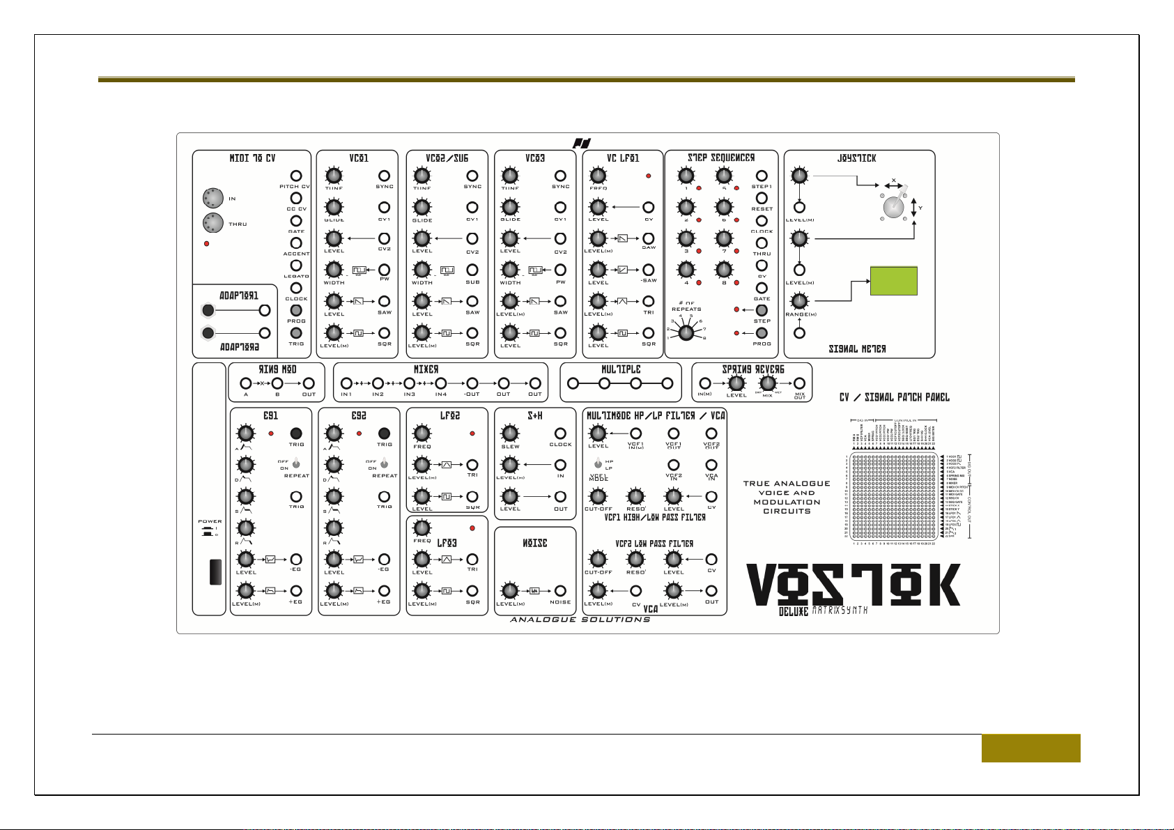
VOSTOK, WHAT IS IT?
Vostok is a self-contained, complete, semi-modular synth comprising real analogue voice and modulation circuits, whose design is based on
circtuits from the 1970s.
Aside naturally from the sequencer controller and MIDI circuits there are no CPUs used in this synth.
When you turn a control, you are directly changing the analogue circuit. The control does not have to go via a CPU first.
Why is this important? If every control and switch is going via a CPU then that means the CPU is keeping every parameter rigidly in place. You
don’t get that subtle drift affecting every parameter, which is part of the analogue sound. It also means you get this nice subtle circtuit
interactions, that and all those little extra unexpected sound artifacts that again make analogue have so much more character than most other
modern analogue and digital synths.
Vostok contains all the essential synth ingredients to make just about any type of bass, lead or sound effect you’d expect of a modular synth.
4 Vostok, what is it? | Analogue Solutions
Vostok Deluxe
INTRODUCTION
Congratulations on buying the Vostok synthesiser. Vostok is part of the Analogue Solutions range of analogue music equipment. Vostok is a
precision electronic musical instrument. It combines all the often needed music electronic circuitry to make a music synthesiser in one compact
module.
No compromise has been made with the construction of Vostok. Cheaper options in parts have not been used;
Full rugged steel/aluminium case - no plastic mouldings
Good quality smooth potentiometers, fully sealed against dust
Good quality knobs with spun aluminium caps and rubberised pots.
High grade double-sided circuit board
High Quality 16bit DAC for MIDI-CV conversion
Very stable MIDI to CV
Stable analogue oscillators
Hand built by humans
True retro analogue voice and modulation circuits to give an authentic retro sound
1970s retro sound
Spring Reverb
Analogue Solutions | Introduction 5
Vostok Deluxe
BRIEF OVERVIEW
Vostok is a self-contained TRUE analogue synthesiser. The voice and modulation circuitry are entirely analogue, using all discrete and op-amp
components.
Vostok uses a 12dB per octave multimode filter which has plenty of character. The two filters can be combined to act as a single 24dB per
octave LPF.
APPLICATIONS
MONO SYNTHESISER
Vostok is for use any time you need analogue sound effects, fat basses, screaming leads, beeps, tones, zaps, and all the other crazy sounds
associated with analogue synthesis. Use in place of your boring digital synth’s and DSP soft synth’s.
EFFECTS PROCESSOR
Vostok has an audio input socket, so you can feed external sounds into the on-board analogue filters or spring reverb for analogue processing.
This sound could come from an audio track on your DAW (for example a vocal track), from a sampler, or even, say a CD player.
6 Introduction | Analogue Solutions

Vostok Deluxe
DRUM SYNTHESISER
It is easy enough to patch this synth up to create all sorts of electronic percussion sounds, including, snares, kicks, hihats, metal sounds.
Analogue Solutions | Introduction 7

Vostok Deluxe
SAFETY INSTRUCTIONS
Please read carefully before using:
Only use the correct power adaptor. 230V (or 115V whatever your country needs). Check side panel to see what voltage the unit has been
set up to take.
Never handle the power cable or the unit with wet hands.
Never excessively bend the adaptor cable or get it trapped or place heavy objects on it. If the adaptor cable becomes damaged, replace the
adaptor.
Ensure the unit is disconnected from the mains before moving or cleaning.
Always disconnect the unit from the mains if there is lightning in your area.
Ensure the unit is on a stable surface, and never place heavy objects on top of it.
Never allow young children or animals to operate the unit or adaptor.
Do not use excessive force when using the controls or inserting cables to the connectors.
The unit should not be operated in the rain or near water and should not be exposed to moisture.
If the unit is brought from a cold environment to a warm one, the unit should be left to reach the ambient temperature.
Keep away from heat sources, such as radiators, ovens, heaters etc.
Never allow it to get wet. Do not operate it near water, like pools, sinks, bathrooms etc.
Do not place beverages on or near it.
Never open the case or attempt to make repairs. Refer any servicing to qualified service personnel.
8 Safety Instructions | Analogue Solutions

Vostok Deluxe
PREVENTING DAMAGE TO OTHER CONNECTED DEVICES;
Vostok has a very high dynamic range. It is capable of produce loud signals of very high and sub-sonic frequencies that could blow
inadequate speakers if played too loud. It is recommended that input levels to external equipment (mixers, amp's etc.) are kept low when first
connected, and then slowly increased to a useable level.
MAINTENANCE INSTRUCTIONS
Any cleaning of the Vostok case should be done with a clean lint-free cloth. DO NOT USE SOLVENTS OR CLEANERS, as this will deteriorate
the exterior appearance of the equipment.
MOUNTING
Mounting does not mean 'place on the wall' or 'to make love to' in this instance. Place Vostok soundly on any stable surface so he cannot fall
off or over, causing it or yourself injury.
POWER
The unit must be connected to the mains using an earthed and fused IEC power lead. Ensure the voltage indicated on the rear panel matches
your mains outlet. It will be factory set to either 115V (USA) or 230V (Europe). There is a Voltage select switch inside, but it is advised this is
only changed but a qualified electronics engineer.
SIGNAL TO NOISE / PITCH SCALING
Analogue Solutions | Safety Instructions 9

Vostok Deluxe
Vostok uses analogue circuits, 1970s designs, and components such as op-amps that were originally designed in the 1970s.
Some background noise and odd little noises and crackles can be heard in some instances if you turn down the VCO levels and really crank up
the levels!
This synth was designed using old circuits intentionally to get a old vintage sounds.
With normal use, any background noise will be completely masked and should not prove to be a problem. Indeed, some of these subtle sounds
add to the character.
To get the best signal to noise ratio do what you should naturally do with any audio/music system that is use the highest signal level you can
through out the signal chain.
So keep VCO output levels, Filter input and output, etc at near maximum (maximum could result in pleasurable overdrive!)
Also another odd but desireable consequence of using vintage circuits is you will find the pitch tracking subtley drift a little up the scale. This
gives a great warm chorusing effect when using more than one VCO - another reason why this synth sounds so much more ‘analogue’ than
some modern analogue contemporary synths.
10 Safety Instructions | Analogue Solutions

Vostok Deluxe
INITIAL TUNING
Once the MIDI and audio connections have been made it may be necessary to tune in the VCOs to the rest of your music set-up. Allow a five
minute warm up time.
Patch MIDI-CV Pitch to each VCO’s CV1 pitch control input.
Centre each VCO’s tune control, then one at a time, tune each VCO to a reference source, for instance a guitar tuner.
Analogue Solutions | Safety Instructions 11

Vostok Deluxe
CIRCUIT IN DETAILS
Here follows details on all the sockets and controls, with brief simplified explanations of what the circuits do. We have not gone into technical
details on how or exactly what each circuit does but tried to explain each control's function and effect.
We won’t describe in full detail what a ‘VCO’ is, for example. In principle, a Vostok VCO is the same as any other VCO. We have assumed you
have at least abasic understanding of analogue synthesis and modulars. There are plenty of resources and tutorials on the web explaining the
fundamentals of subtractive analogue synthesis and modular use.
This synth has been designed to be simple and intuitive to use, just like the original analogue synth’s of the 70s and 80s. There are no multilayered menus to work through.
Anyone who has used synthesisers before should be familiar with the terms used and therefore be able to predict their behaviour and how they
affect the sound. The best way to learn how to use Vostok is to go straight ahead and play with it. Reading of this manual may only be
necessary for finer operational detail.
SOME INITIAL NOTES
To get a useful sound from Vostok, some cable patching will be neccesarry. See the ‘Basic Patch’ example at the end of this manual as a
starting point.
Patches can be done entirely with cables, or entirely with just pins. But usually a mixture of both will be best.
There will be some patches or settings that won’t appear to work, or produce less than desirable effects. This won’t be a fault of the synth, just
the nature of modular synths. If you are not happy with a result, re-patch and try again!
12 Circuit in Details | Analogue Solutions

Vostok Deluxe
It’s all about experimentation.
If you are a new to modulars…..
Vostok is a complex machine – don’t expect amazing results instantly. Sound design should be approached in the same way as any other
modular synth. Take small simple steps. Build up slowly. Don’t get too ambicious too early on. It takes experience and work. Once you gain that
experience, you will get good sounds very quickly.
Analogue Solutions | Circuit in Details 13

Vostok Deluxe
CIRCUITS – MAIN PANEL
POWER
In is on! Ensure the correct mains voltage is being used (115V for USA, 230V for Europe). Ensure your Vostok is switched to the correct
voltage.
14 Circuits – Main PANEL | Analogue Solutions
Vostok Deluxe
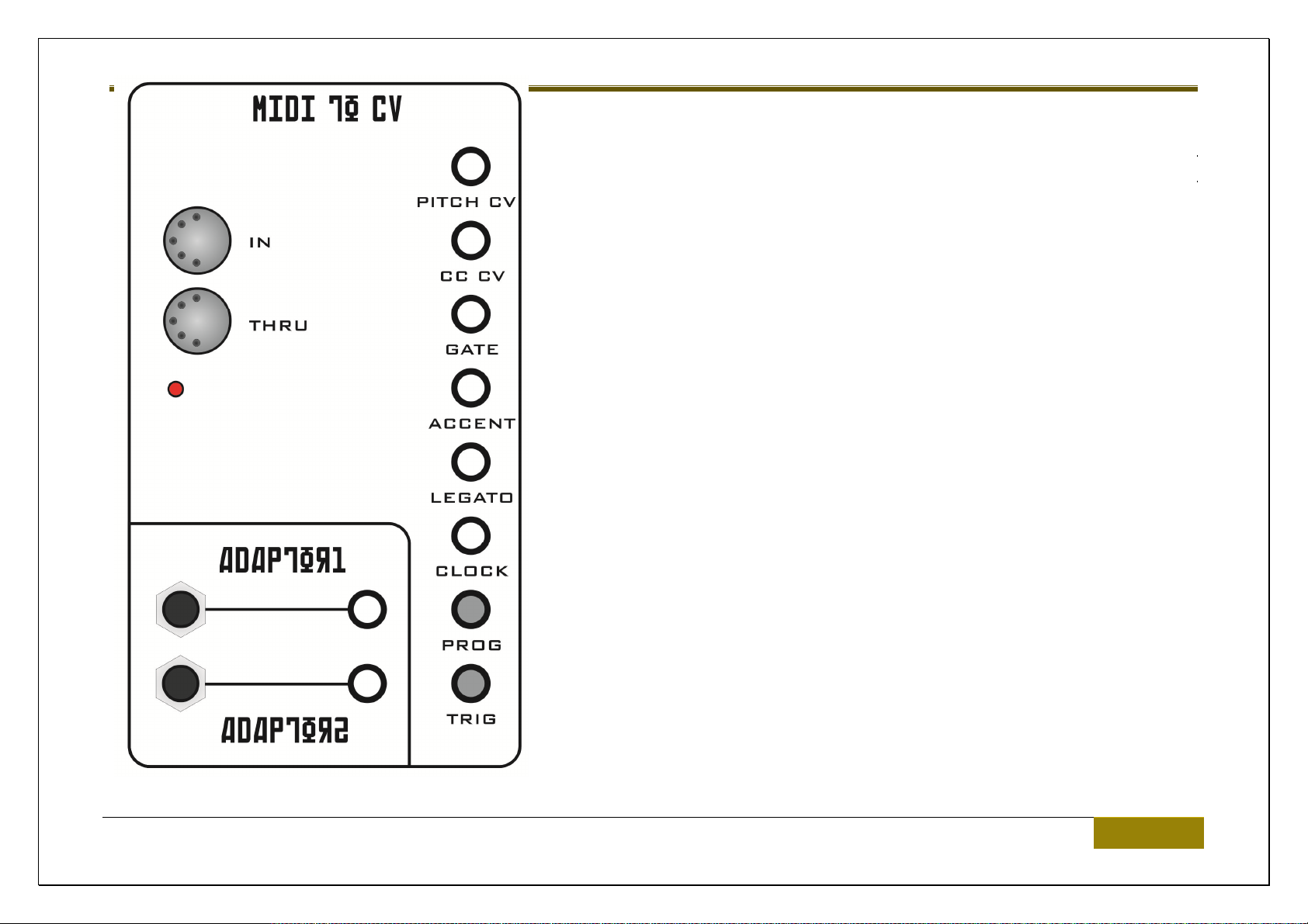
MIDI TO CV
A MIDI to CV converer converts MIDI Note messages into analogue voltages allowing
Vostok to be played using a MIDI keyboard or DAW.
MIDI IN socket
This is the MIDI In socket. Connect to the MIDI Out of your DAW, sequencer or MIDI
keyboard.
MIDI THRU socket
Use to connect further MIDI devices.
PITCH CV socket
This is the 1V/Octave pitch control CV. MIDI note number is converted to a voltage.
Use this to ‘play’ the VCOs.
CC CV socket
Depending how set – this socket outputs a CV that is controlled by either note velocity
or MIDI controller.
Analogue Solutions | Circuits – Main PANEL 15

Vostok Deluxe
GATE socket
This socket outputs 5V when a MIDI Note is held down and returns to 0V when the key is released.
ACCENT socket
Each time a MIDI note with velocity over 80 is received, this socket will output a trigger.
LEGATO socket
If two MIDI notes are overlapped, this socket will output a 5V signal.
CLOCK socket
This converts MIDI Sync to 16th (semiquaver) analogue clock pulses at 4ppqn.
PROG push button
This is used to set MIDI receive channel and CC CV modulation source.
To set MIDI channel:
Push and hold this button, then whilst holding, press some MIDI keys (any note) or move a MIDI controller (for example, Mod Wheel). Then
release the push button.
The MIDI Receive channel will be set to the channel of the notes that were received.
CC CV will be set to velocity if you pressed MIDI notes in the above programming procedure.
If you moved a MIDI controller (e.g. Mod Wheel) the CC CV will be set to that same controller number.
16 Circuits – Main PANEL | Analogue Solutions

Vostok Deluxe
Note: If you have difficulties, try a 2nd or 3rd time – also re-read the above instructions. Also try connecting a MIDI keyboard directly to the
Vostok to set the receive channel.
TRIG push button.
This is a manual trigger button. Push this and a trigger signal will be output from the GATE socket. If patched accordingly, push this to manually
trigger the envelopes, for example.
Analogue Solutions | Circuits – Main PANEL 17

Vostok Deluxe
DUAL ADAPTORS
The adaptors are located just to the left of the MIDI-CV converter block.
These are used to convert a mini-jack to a big jack (either way!)
Normally used when you want to send, or receive, audio from/to and external device such as a mixing desk or DAW that uses a big jack.
18 Circuits – Main PANEL | Analogue Solutions
Vostok Deluxe
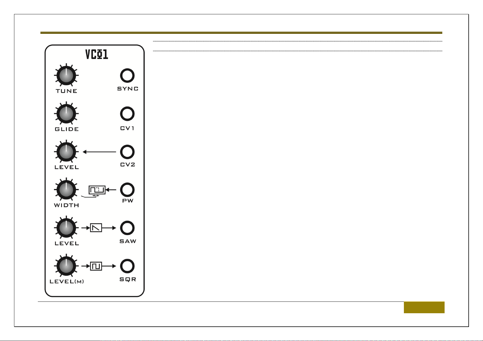
VOLTAGE CONTROLLED OSCILLATORS (VCOS)
These are circuits that produce the initial sound that is then shaped by the filters and amplifiers. They
are what produce the ‘notes’.
They produce a continuous sound/waveform. Normally this is used as audio for the filters, but they can
also be used as modulation signals.
There are three analogue VCOs. They can all be used together to make sound, or just some can be
used for sound, and others as modulation sources.
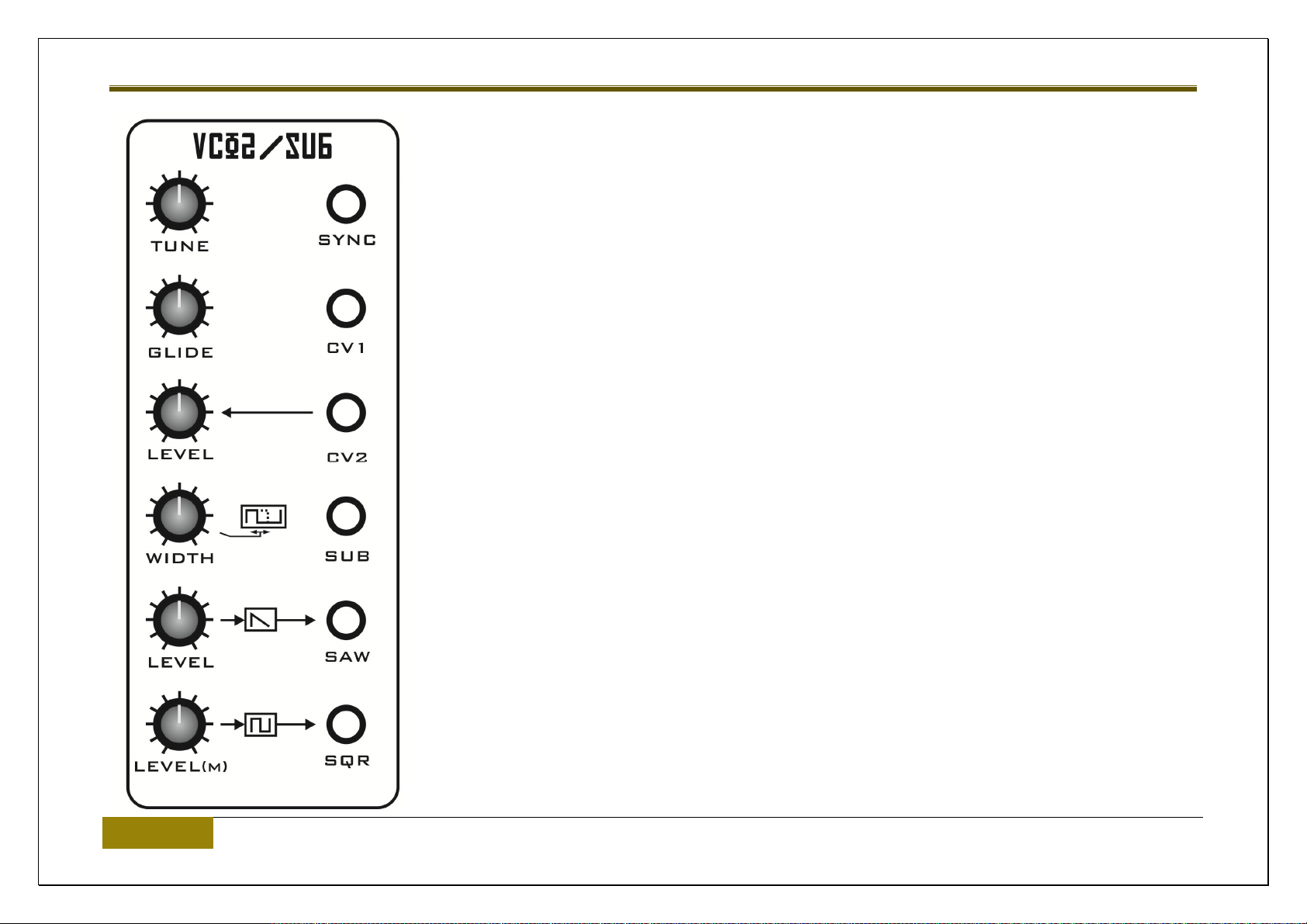
VCO1 and VCO3 are Identical. The only difference VCO2 has is that instead of a PW CV control
socket it has a SUB-OSC audio output.
First we will go over what they have in common
TUNE control
Sets the initial Pitch of the VCO.
GLIDE control
Analogue Solutions | Circuits – Main PANEL 19
Vostok Deluxe
This control sets the time it takes for the pitch to change from one note to another. When a new
voltage is set to change the pitch of the VCO, is will glide from the old note to the new note.
When set to zero, then there is no glide (portamento), and pitch changes will be instantaneous.
Gradually turning clockwise increases the time.
LEVEL control
This is an attenuator for any signal fed into the CV2 modulation input socket.
WIDTH control
The Width changes the duty cycle/pulse width of the square wave output. This changes the tone of the
Square Wave. Note, this control is not an attenuator for the PW CV socket described later.
LEVEL (saw and square) control
This is an attenuator / output level control for the Saw and Square wave form audio outputs.
SYNC In (VCOs 1 and 3 only)
It is possible to reset the waveform using an external signal. Normally audio from another VCO would
be patched into here. Then when the pitch of the VCO is changed, interesting new harmonics can be
heard.
CV1 socket
20 Circuits – Main PANEL | Analogue Solutions

Vostok Deluxe
This is a pitch CVh control input socket. The is pre-glide. Normally the output of a CV keyboard, or the MIDI-CV converter PITCH CV output
would be patched here.
CV2 socket
This is a modulation CV control input socket. The is post-glide. Normally the output of a LFO or would be patched here.
PW socket (VCOs 1 & 3 only)
This is a modulation CV input socket to control pulse width with an external voltage such as LFO or EG.
SUB socket (VCO2 only)
This is the sub-osc audio output. Sub-Osc is an audio output from the VCO that is one octave lower than the other Saw/Square outputs. Mix
with the other waveforms for a deeper, fuller sound. Great for bass!
SAW socket
This is the Sawtooth waveform audio output
SQR socket
This is the Square waveform/PW waveform audio output.
Analogue Solutions | Circuits – Main PANEL 21
Vostok Deluxe
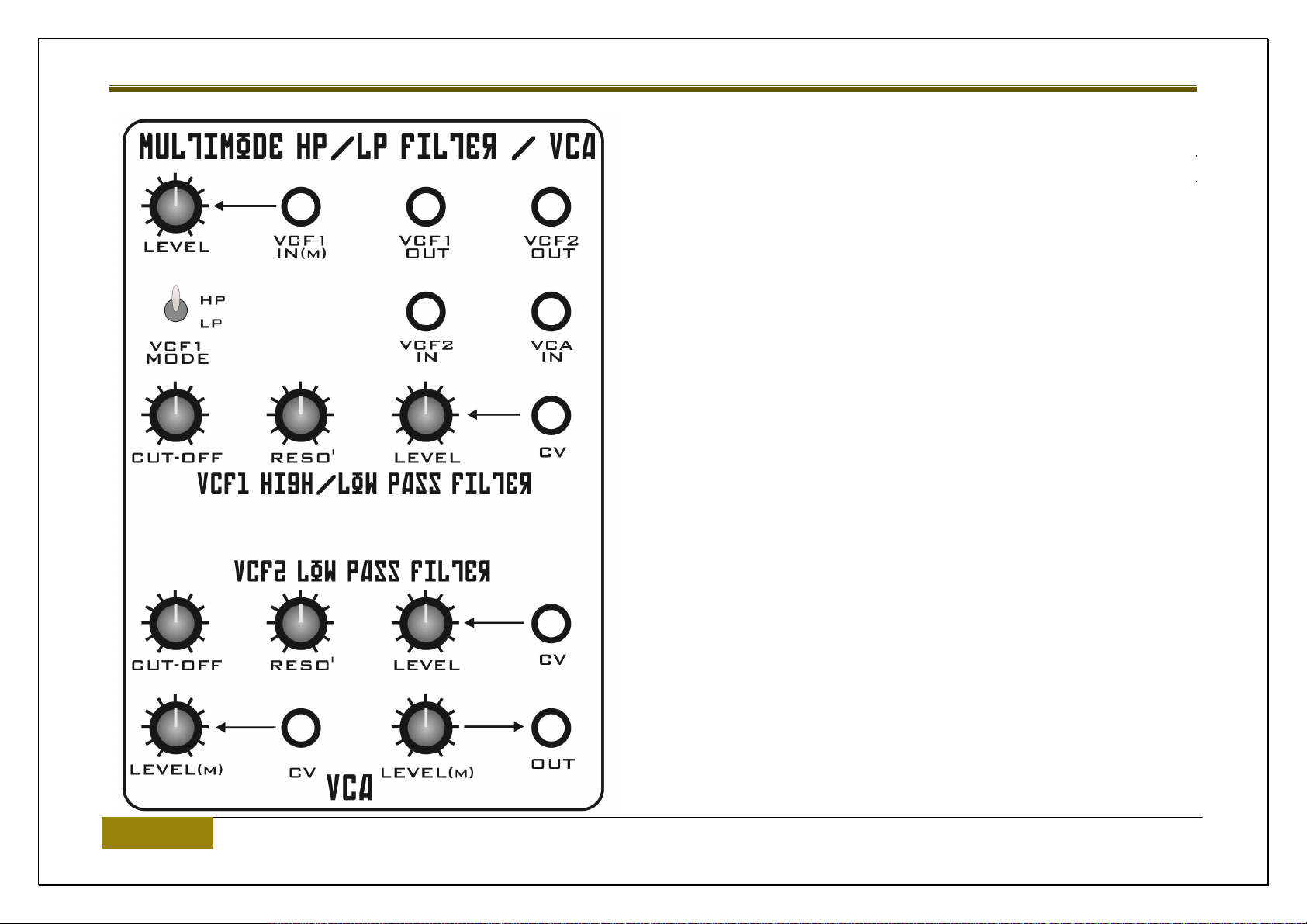
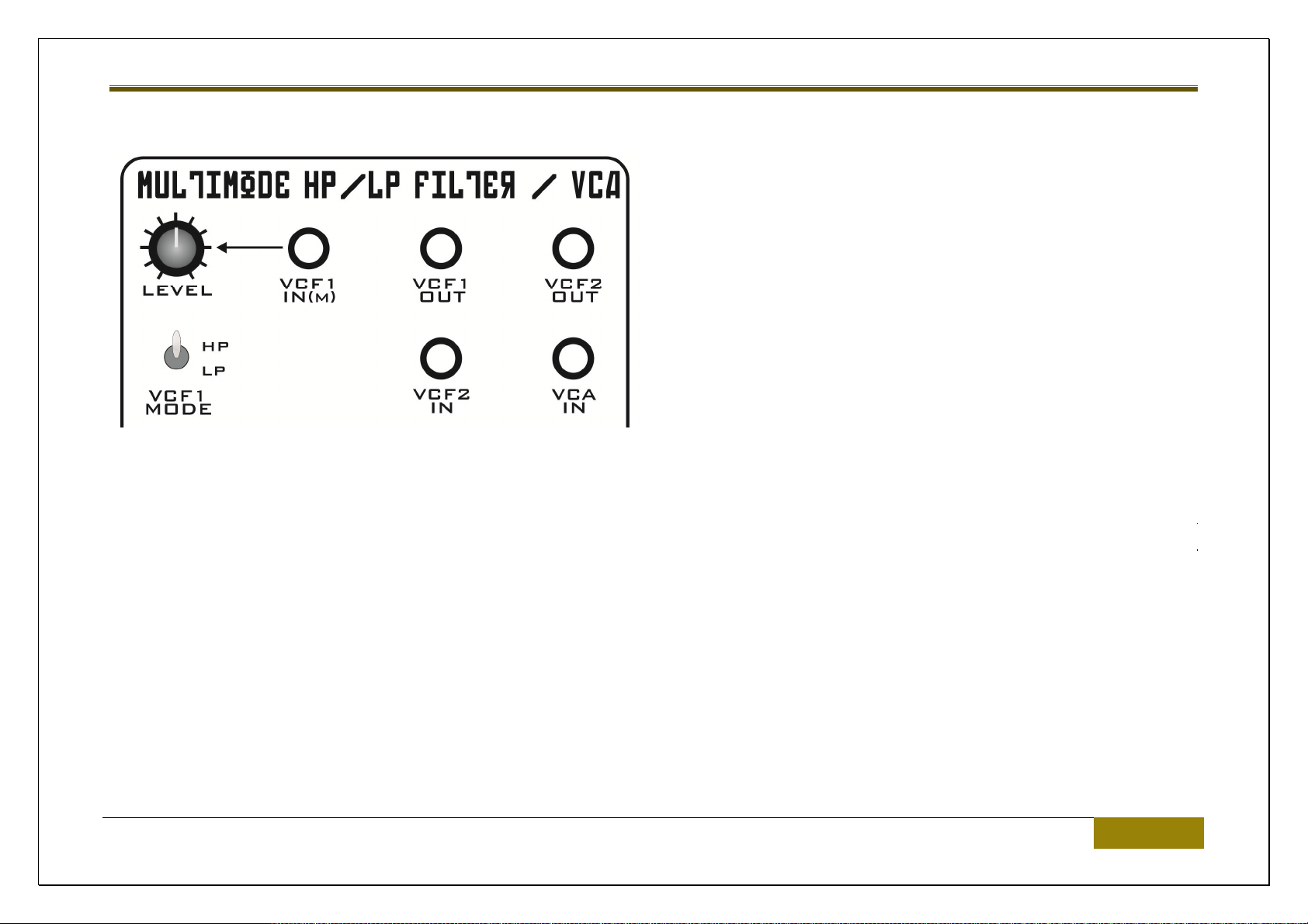
DUAL VCF / VCA
Vostok has a multimode filter similar to that found in the vintage MS20 –
though modified for more versatility. Don’t think of it as a MS20 clone,
since Vostok’s filter has developed a character of its own.
It comprises two 12db filters. One is switchable between high and low
pass, and the other is low pass. Together they can be combined to be
band pass filter or 24db low pass filter.
The VCA is in the same general block of front panel as the two VCFs.
A voltage controlled filter (VCF) is used to change the tone/frequency
content of the raw oscillators.
22 Circuits – Main PANEL | Analogue Solutions
Vostok Deluxe
VCF1 (HP/LP SWITCHABLE)
LEVEL control
This is the input level attenuator for the audio signal fed into the filter through the VCF1 IN socket.
VCF1 IN socket
This is the audio input to VCF1.
Analogue Solutions | Circuits – Main PANEL 23

Vostok Deluxe
VCF1 OUT socket
This is the audio output from VCF1 filter.
VCF1 MODE toggle switch
When up, VCF1 performs as a highpass filter (HP). When down, performs as a lowpass filter (LP).
CUT-OFF control
This sets the filter cut-off frequency. It is used to change the tonal characteristics of the audio going through the filter.
RESO’ control
The Resonance control increases feedback at the filter cut-off frequency. What some people like the technically refer to as squigyness.
LEVEL control / CV socket
This is the filter cut-off modulation CV input. The LEVEL control is the signal level/modulation strength conrol.
24 Circuits – Main PANEL | Analogue Solutions
Vostok Deluxe
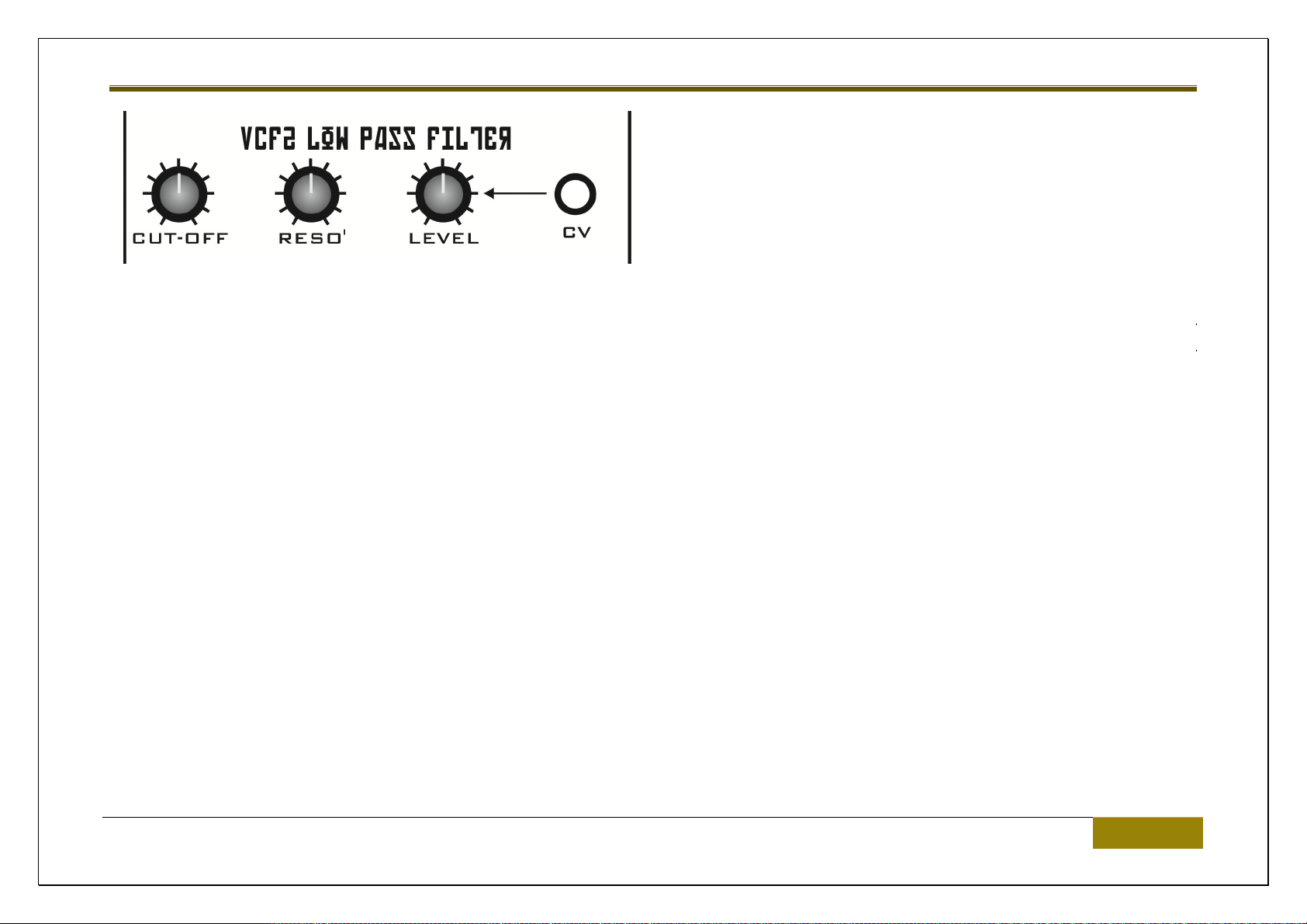
VCF2 (LP)
CUT-OFF control
This sets the filter cut-off frequency. It is used to change the tonal characteristics of the audio going through the filter.
RESO’ control
The Resonance control increases feedback at the filter cut-off frequency. What some people like the technically refer to as squigyness.
VCF2 IN socket
This is the audio input to VCF2.
VCF2 OUT socket
This is the audio output from VCF2 filter.
Analogue Solutions | Circuits – Main PANEL 25

Vostok Deluxe
LEVEL control / CV socket
This is the filter cut-off modulation CV input. The LEVEL control is the signal level/modulation strength conrol.
26 Circuits – Main PANEL | Analogue Solutions

VCA IN socket
This is the audio input to the VCA.
Vostok Deluxe
VCA
LEVEL control / CV socket
This controls the modulation level of the control signal fed into the VCA CV socket. The higher the signal, the higher the amplification.
LEVEL control / OUT socket
This is the audio output signal level/attenuator control. The VCA audio signal is output from the OUT socket
Analogue Solutions | Circuits – Main PANEL 27

Vostok Deluxe
LFO 1, 2, 3
Vostok has three LFOs. LFOs 2 and 3 are identical. LFO speed is voltage controlled.
Typically use LFOs to add modulation to pitch (vibrato), filter cut-off (wah-wah) and VCA level
(tremolo).
LFOs can also be used to clock the Sequencer or trigger the Envelopes
FREQ control
The Frequency control changes the speed of the LFO.
LEVEL control and CV socket
You can alter the speed of LFO1 using a control voltage. For example, an EG output or the
Sequencer CV output. The Level control alters the amount of CV modulation.
WAVEFORM controls and CV sockets
There are Sawtooth, inverse Sawtooth, Triangle and Square wave outputs from the LFOs. The level of each output can be altered with the
Level control.
28 Circuits – Main PANEL | Analogue Solutions

Vostok Deluxe
Analogue Solutions | Circuits – Main PANEL 29

Vostok Deluxe
30 Circuits – Main PANEL | Analogue Solutions

Vostok Deluxe
SIGNAL SUMMER / MIXER
The mixer is typically used to mix the audio outputs from each oscillator so they can then be fed to the filter. Take each VCO audio output and
patch to the mixer inputs.
Patch the mixer OUT socket to the filter VCF1 IN audio input socket.
It is possible to overdrive the mixer for a crunchier sound. If you want a smoother sound you may have to slightly reduce the Level controls.
It can in fact be used to mix control voltages too. Note, however, you wouldn’t normally want to mix CVs and audio at the same time!
There are four audio input sockets to the mixer. There are three audio outputs. The first one is inverted. This would be used if you wanted to
invert a signal. For example, patch a EG into the Mixer. Then the –OUT will produce the EG signal but upside-down!
Analogue Solutions | Circuits – Main PANEL 31
Vostok Deluxe
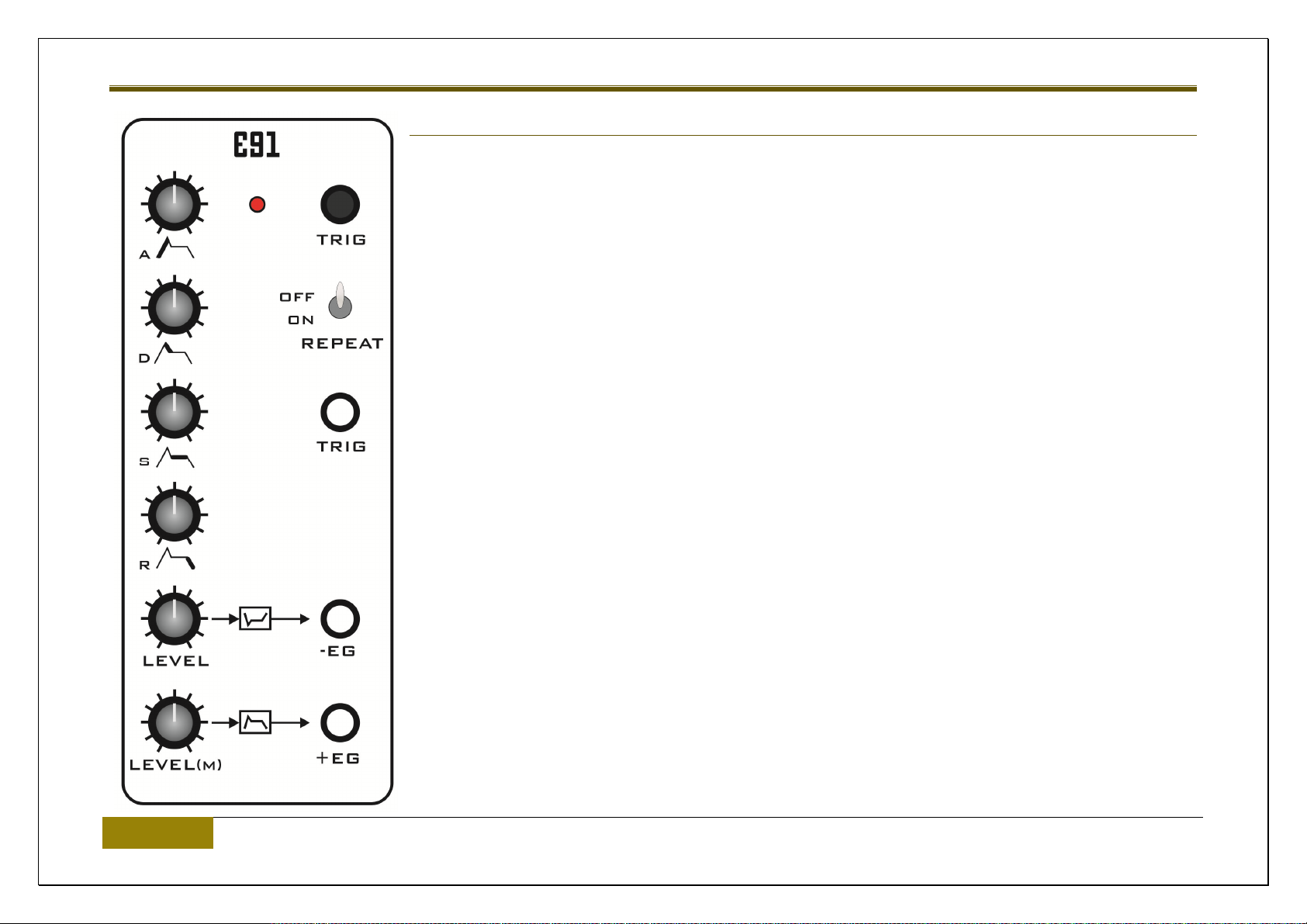
ENVELOPE GENERATORS (EGS)
The EGs produce a control voltage that varies over time. Typical used to shape the volume of a sound
when controlling the VCA, or the tone, when controlling filter cut-off.
But can also be used to modulate, say, the pitch, for drum effects, or, pulse width, for brassy sounds.
There are two EGs and they are identical to each other.
A control
Attack: This controls how low the EG takes to reach maximum level once triggered.
D control
Decay: After reaching maximum level following the Attach stage, Decay sets the time taken to
reach the level set by Sustain.
S control
Sustain: Once the Attack and Decay stages have passed, Sustain sets the level that the EG will
hold its output at for as long as a key is held down.
R control
Release: Once the key is released, this sets the time take for the signal to fade to zero.
32 Circuits – Main PANEL | Analogue Solutions
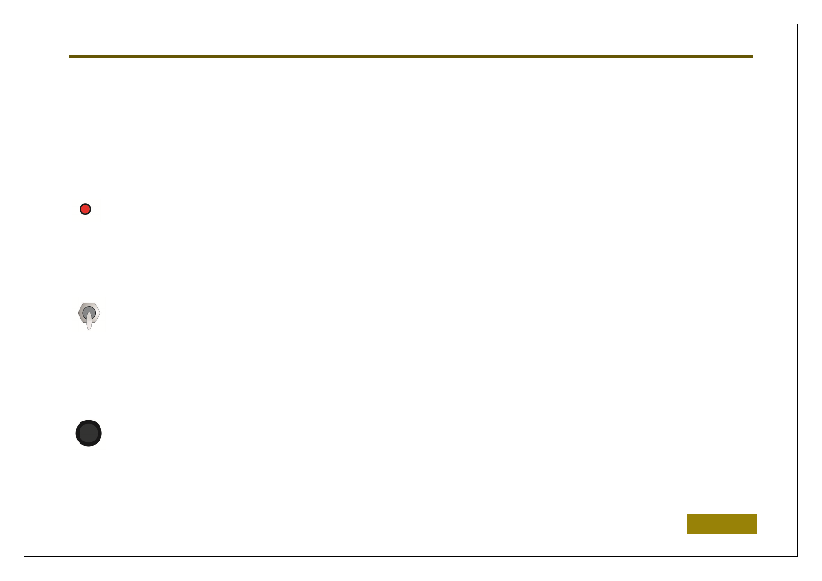
TRIG push button
Push this button to manually trigger the EG.
LED
The LED gives a rough approximation of output level.
REPEAT toggle switch
Vostok Deluxe
When this switch is down the envelope will repeat like a LFO – for as long as there is gate voltage present at the input (a key held
down). Attack and Decay will affect the wave shape and speed of the LFO affect.
TRIG socket
This is the input socket for an external trigger signal, eg, use an LFO square wave to trigger the EG.
Analogue Solutions | Circuits – Main PANEL 33
-EG socket
This is the CV output of the EG, but the signal is inverted.
+EG socket
This is the CV output of the EG
-EG and +EG also have their own LEVEL attenuators.
Vostok Deluxe
34 Circuits – Main PANEL | Analogue Solutions

Vostok Deluxe
Analogue Solutions | Circuits – Main PANEL 35
Vostok Deluxe
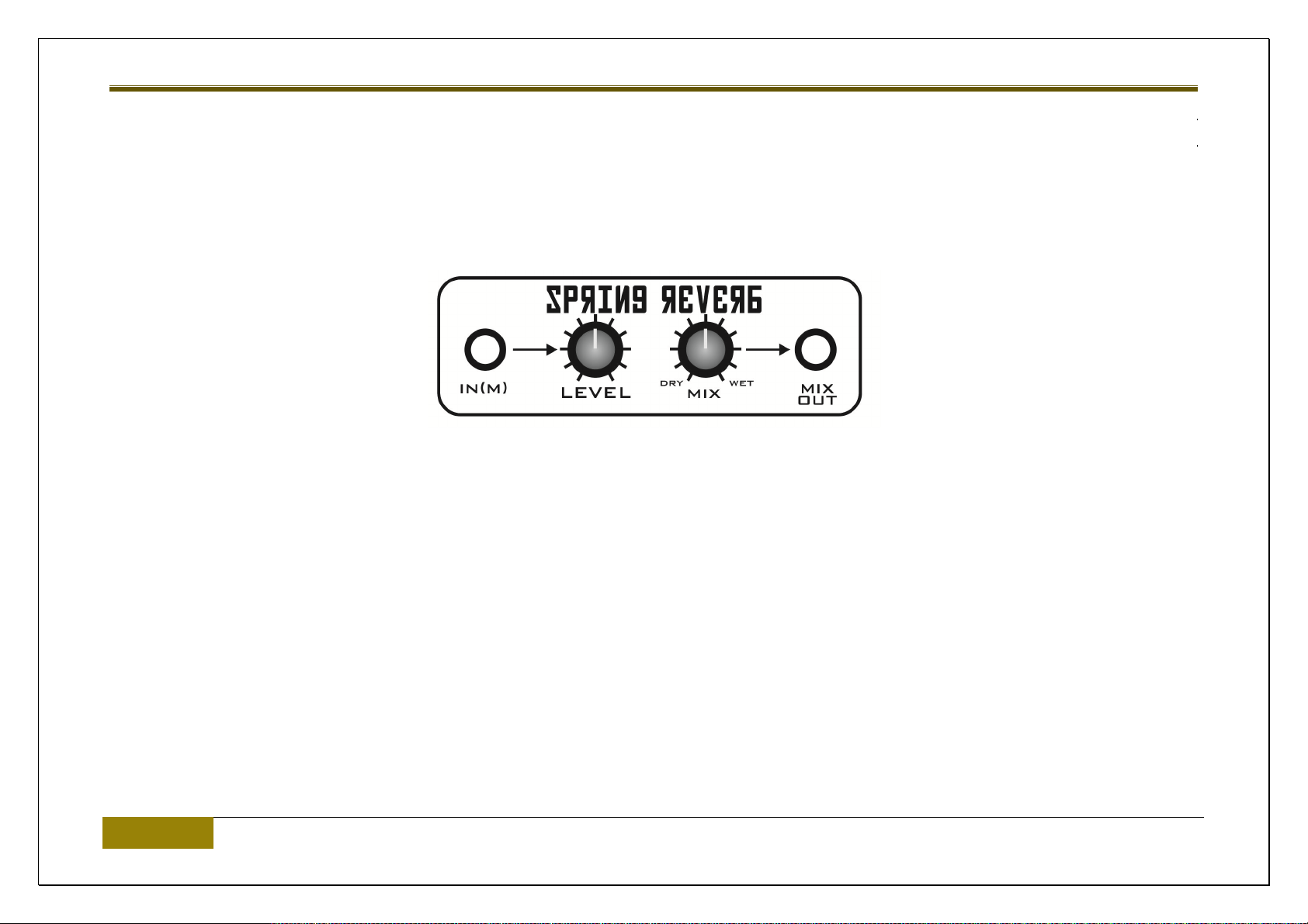
SPRING REVERB
The spring reverb is a vintage effect. It was a pre-digital solution in getting artificial reverberation.
Vostok uses a high quality triple spring Accutronics unit.
Ordinarily, you would patch this in at the very end of the signal chain, just like a traditional effect. But, for more fun, why not try patching it
between the mixer output and the filter input, for example?
IN socket
This is the audio input to the spring.
LEVEL control
This is the input level control.
36 Circuits – Main PANEL | Analogue Solutions

Vostok Deluxe
MIX control
This is a balance control between the dry input signal and the wet spring reverb sound.
MIX OUT socket
This is the audio output from the MIX balance control / spring reverb.
Note; spring units are typically ‘quite noisey’ compared with modern effects, and even some other types of vintage effects. So don’t expect a
perfect signal to noise ratio. Always try to keep the audio level of the input signal as high as possible – but too high and you may get it to distort!
It is normal to here a metallic boing sound if the case is knocked or moved since a spring reverb is a mechanical effect!
Analogue Solutions | Circuits – Main PANEL 37

Vostok Deluxe
LOWER SECTION / EXPANDER PATCH PANEL
MULTIPLE
A multiple is used to split signals. It is not a mixer!
It would typically be used to split an audio or CV so that it can be fed to more than one source.
38 Circuits – Main PANEL | Analogue Solutions
Vostok Deluxe
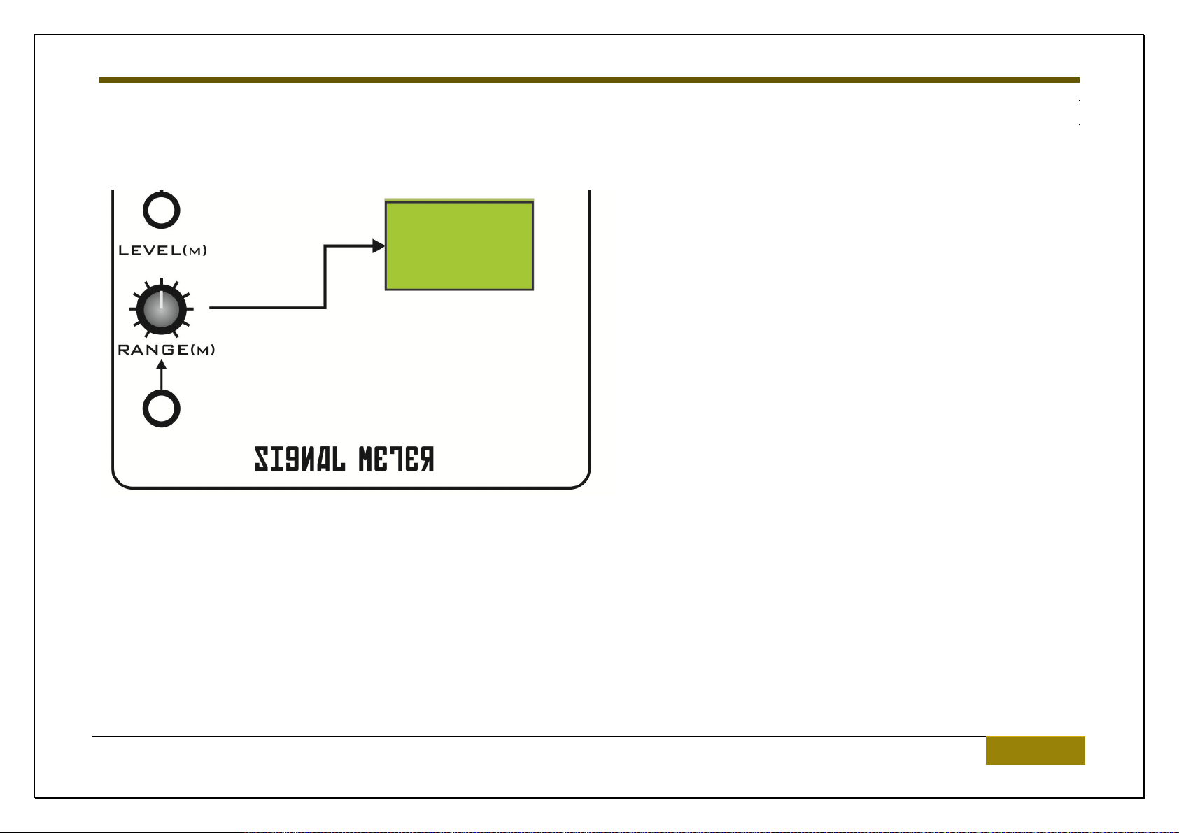
VU / SIGNAL METER
The signal meter is used for a general overview of a signal – either audio or control voltage. It is not calibrated to any particular range so do not
use it to measure signals!
RANGE control
This is an input level / attenuator control for the signal fed to the
Meter via the socket.
Start with the Range set to minimum. Slowly increase the Range
until you get full scale deflection. Try not to overdrive the meter
(do not have the metal hitting full scale/range too often)
Analogue Solutions | Circuits – Main PANEL 39
Vostok Deluxe
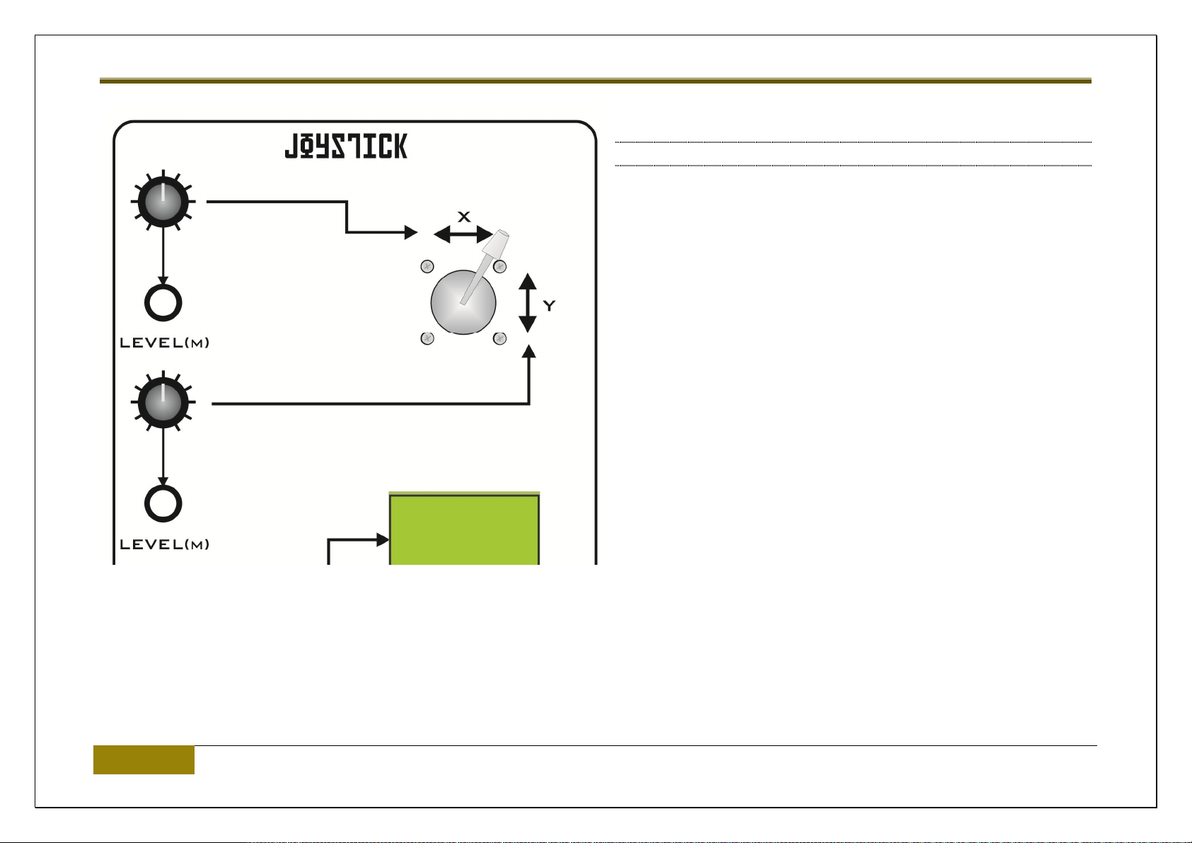
JOYSTICK
The joystick has two axis – X and Y.
A control voltage is produced from each. Maximum range is -12V to
+12V.
The X and Y controls and sockets are essentially identical.
LEVEL control
This is a level / range control for the CV output fed to the socket.
This is a gate voltage that is produced each time MIDI note 01 is
received.
This could, for example, be patched to the Sequencer’s RESET input, so the sequencer can be programmed to reset using MIDI Note 01.
40 Circuits – Main PANEL | Analogue Solutions
Vostok Deluxe
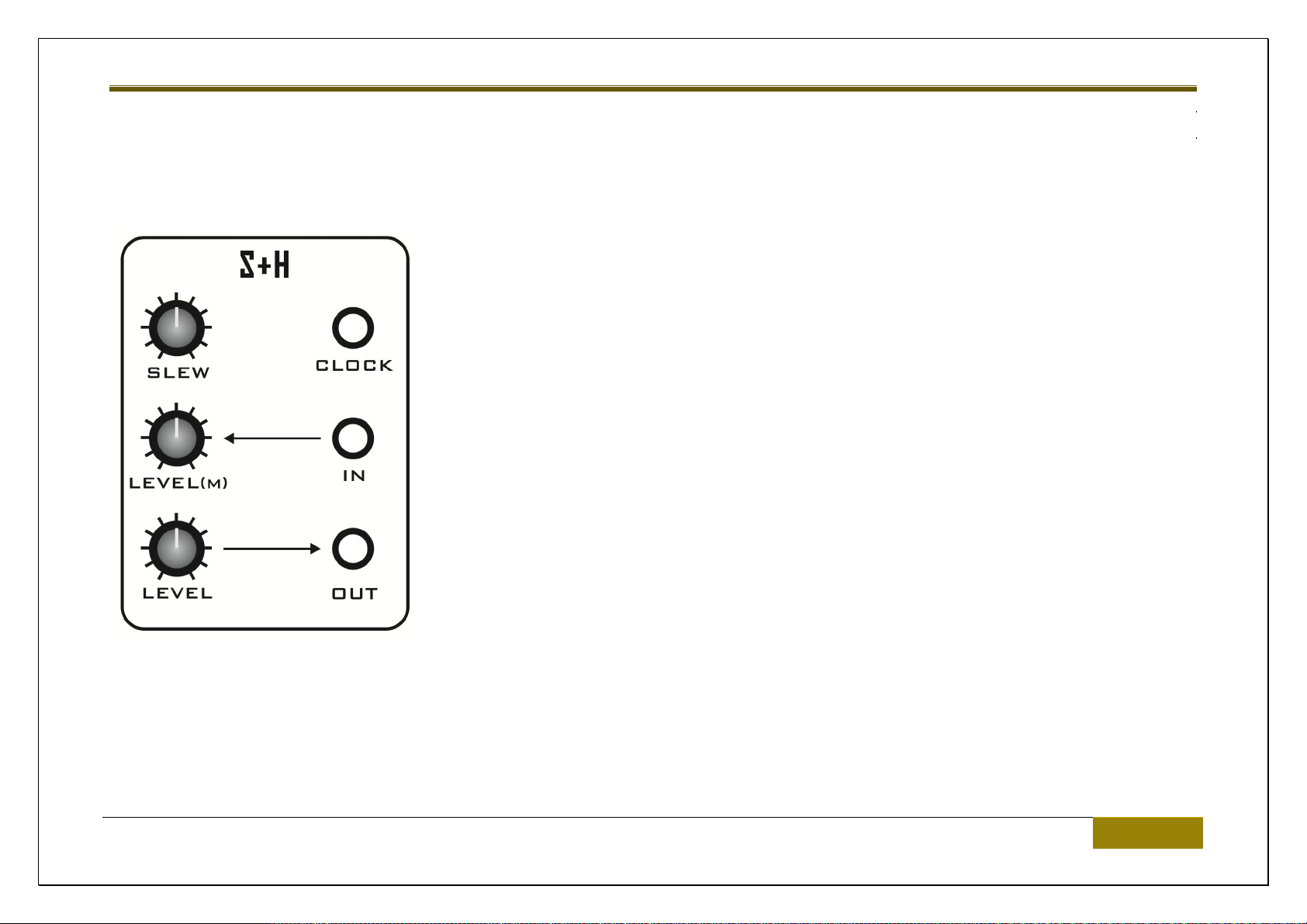
SAMPLE & HOLD (S+H)
A sample and hold will ‘record’ a voltage level and hold it there.
IN socket
This is the signal input socket. Usually use Noise – for a random effect, or some other signal like EG or LFO triangle.
Analogue Solutions | Circuits – Main PANEL 41

Vostok Deluxe
LEVEL control
This is level control for the signal input (above).
OUT socket
This is the CV output from the sample and hold circuit. Maybe try patching this to filter cut-off or VCO pitch.
LEVEL control
This is the S+H signal output level control.
CLOCK socket
This is the S+H clock input socket.
Each time the input signal goes high the input signal will be sampled and held, until the next clock.
Typically use the square wave output from an LFO, or, the Gate signal from the MIDI converter.
A typical use of S+H is to create a stepped random voltage. To do this patch Noise to the IN, LFO square wave to the CLOCK.
SLEW control
Slew is like portamento. Use this control to smooth out sudden changed in voltage change at the S+H output.
42 Circuits – Main PANEL | Analogue Solutions
Vostok Deluxe
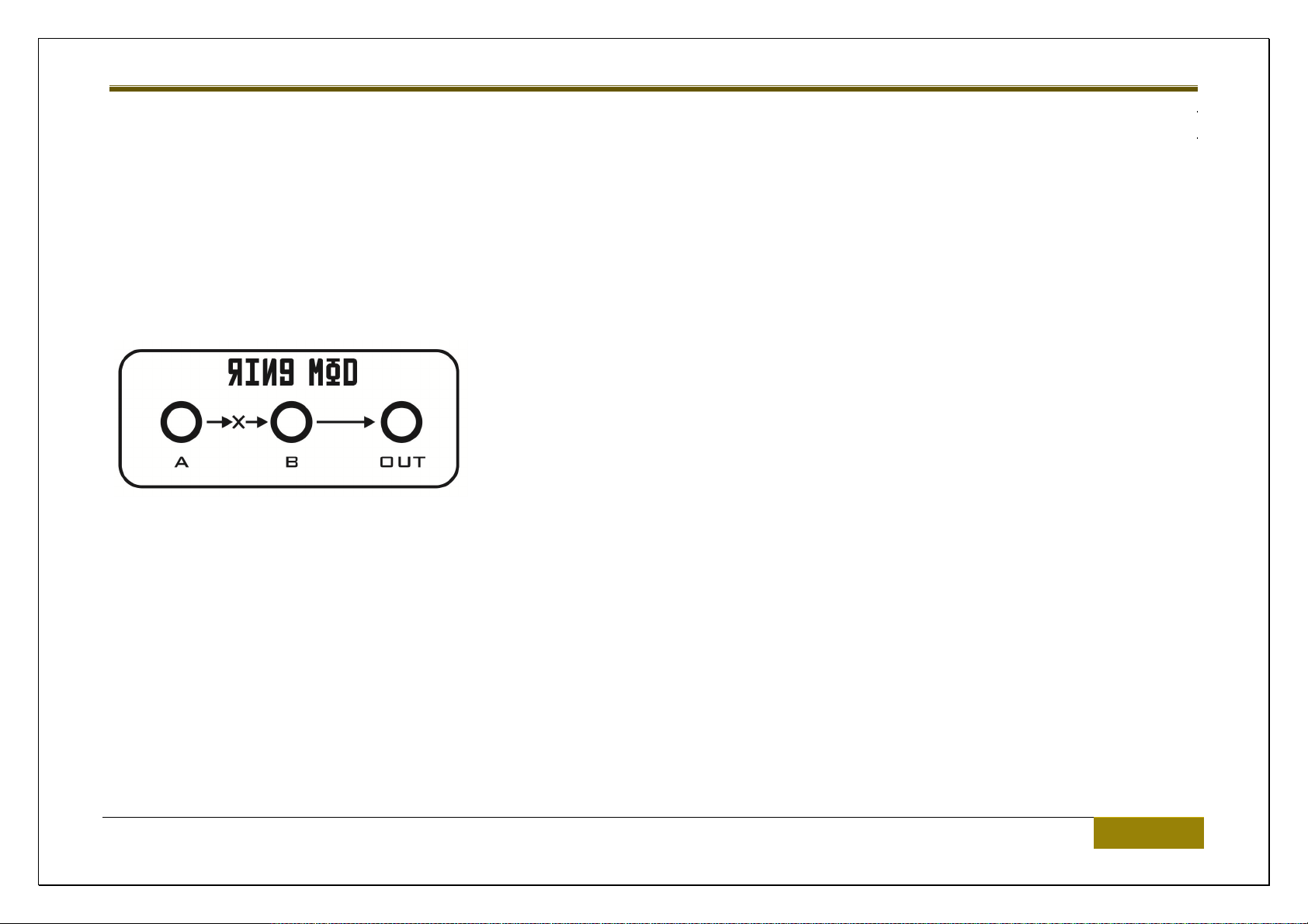
RING MOD
RM takes two audio signals, multiplies them together, and produces a rich harmonic sound. Typically used to create metallic and bell type
sounds.
For best results, use two VCO audio outputs and patch into the two RM inputs. Then take the output to the mixer, and further onto the filter for
further processing.
A and B are the signal inputs.
The signal output is taken from the OUT socket.
Analogue Solutions | Circuits – Main PANEL 43

Vostok Deluxe
NOISE
Noise generator literally produces noise, white noise in fact.
This can be used as a signal source for the Sample and Hold generator (for random voltage effects). Or, can be patched to the mixer, to make
percussion and wind sound effects.
LEVEL control
This is the attenuator control for the noise level.
NOISE socket
This is the signal output.
44 Circuits – Main PANEL | Analogue Solutions

Vostok Deluxe
Analogue Solutions | Circuits – Main PANEL 45

Vostok Deluxe
ANALOGUE SEQUENCER
46 Circuits – Main PANEL | Analogue Solutions

Vostok Deluxe
STEP controls
It is an 8 step sequencer, so there are 8 controls! Voltage range is approximately 0-5V.
STEP LEDs
These light up in turn to show the active step.
# OF REPEATS control
This determines how many times each step is played before the sequencer advances to the next step. Each step can be repeated from
between one to eight times.
This gives the effect of the sequencer being up to 64 steps long! Using a repeat setting of three gives a ¾ time feel.
STEP ONE socket
This socket will output a 5V Gate when ever the sequencer is on step one.
RESET socket
Send a 5V gate to this input socket to reset the sequencer to step one.
CLOCK socket
Analogue Solutions | Circuits – Main PANEL 47

Vostok Deluxe
This is the sequencer’s clock input. Use 5V gate trigger pulses. You can often use LFO square waves too! Using a triangle wave can
sometimes create random patterns.
To sync the sequencer to MIDI we recommend using the Gate output of the MIDI to CV converter. Then create a ‘clock’ sequence using your
DAW or MIDI sequencer by programming a sequence of notes (16ths, for example).
THRU socket
This is a copy of what is fed into the CLOCK socket. Use to send the clock signal to another module.
CV socket
This is the CV output signal generated by the sequencer. Feed to VCO pitch or Filter cut-off, for example.
GATE socket
This is the gate output signal generated by the sequencer. Feed to EG trigger input, for example.
PROG push button
This button toggles on/off the selected step’s Gate. When off, no gate is output for that step, when on a gate will be output for that step (when
the sequencer is running). The LED will indicate whether the current step’s Gate is set to on or off.
It is best to stop the sequencer when setting the steps’ Gates on or off.
STEP push button
48 Circuits – Main PANEL | Analogue Solutions

Vostok Deluxe
Pushing this button steps the sequencer forward one place. Typically this would only be used when the sequencer is stopped. The LED will
light each time the sequencer is clocked.
Analogue Solutions | Circuits – Main PANEL 49
Vostok Deluxe
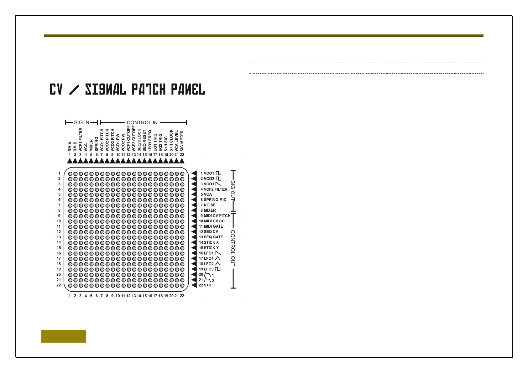
PIN MATRIX
The utilization of a pin matrix panels vastly reduces the number of patch
cables required to patch up a sound. This means you have less cables
hanging over the front panel getting in the way of the controls.
Also the matrix panel enables signals to be split or ‘mixed’
Notes:
Be aware that the pins are quite fragile. Take care to insert and extract
slowly and perpendicular to the front panel.
The matrix panel is not buffered itself, but many of the input circuits and
output circuits are. Generally, you will not see a drop in signal when pins are
inserted, but not in all cases.
Using the 10K Ohm matrix pins usually ‘mix’ the signals better – but in some
cases a small drop in signal level may result.
Use either the small zero Ohm ‘shorting’ pins, or the longer 10K ‘resistor’
pins. Try either – use which gives the best result for what you are trying to
achieve.
There are simply too many combinations of patches to describe in detail on
what patch is effective and which is not.
50 Circuits – Main PANEL | Analogue Solutions
Vostok Deluxe
It is possible to create entire synth patches using just pins, or even just cables, but usually a combination of both is required.
Analogue Solutions | Circuits – Main PANEL 51
Vostok Deluxe
OTHER
HANDLE
The heavy duty handle not only looks good but you will find it comes in great use when you need to move the Vostok to a new location!
PATCH CABLES
Vostok uses mono 3.5mm / mini-jack ‘standard’ CV cables. Stereo plugs may cut out the signal / ground it to earth so do not use.
Take common sense care when patching. The sockets are very strong, however, never use unnecessary sideways force when inserting or
removing patch cables.
52 Other | Analogue Solutions

Vostok Deluxe
PATCH EXAMPLES
NOTES;
These are just examples, not rules. The control positions are just suggestions – a starting point. Of course play around with the settings if it
doesn’t quite sound OK.
Use them as a guide to help you along. Experiement and try things for yourself.
Pay closest attention to the cable patches examples. We have shown only some examples of where to set the controls and switches, in general
the important ones. But not all.
You can clearly set controls such as TUNE or PORTAMENTO to suit.
If a control or switch is shown without a position, it generally means set this how you want.
Switch, Control and Cable positions have been shown in Yellow.
Analogue Solutions | Patch Examples 53

Vostok Deluxe
PATCH 1; BASIC SYNTH PATCH
This is the main patch to memorise. It sets up Vostok to act like a ‘traditional mono synth’. For playing typical leads, basses, etc. It uses patch
cables only. When you are new to modulars, or this synth in particular, you may find it easier to start with just cables. Pins are very useful, but it
can be harder to see what’s going on, until you are more experienced.
The signal chains are ‘typical’; Audio: VCOs->Mixer->VCF->VCA->Reverb->Adaptor->external mixing desk/DAW. CVs: EGs->VCA/VCF
54 Patch Examples | Analogue Solutions

Vostok Deluxe
Analogue Solutions | Patch Examples 55
Vostok Deluxe
PATCH 2; USING RING MOD
Shows typical use of ring mod to create metal type sounds. Patch 2 VCOs to the Ring Mod and take the output to the mixer (or straight to the
filter). Alter pitches of the 2 VCOs for crazy sounds.
56 Patch Examples | Analogue Solutions

Vostok Deluxe
PATCH 3; USING SAMPLE AND HOLD
This patch shows typical use of Sample and Hold. It uses the Noise Generator to create a Random voltage that changes each time a clock
pulse received. Instead of noise, also try EG output, or LFO Triangle (use a different LFO than that used to clock it).
Analogue Solutions | Patch Examples 57

Vostok Deluxe
PATCH 4; HOOKING UP THE ARPEGGIATOR
The Arp’ must receive a clock signal to work. Either use LFO square wave, MIDI Clock, or better still, MIDI Note 00 – so you can step as
required using a MIDI sequencer.
58 Patch Examples | Analogue Solutions

Vostok Deluxe
Analogue Solutions | Patch Examples 59

Vostok Deluxe
SPECS
Size: 190 (depth including lid) x 660 (width) x 410 (height excluding handle) Cm
Mass: 13.2Kg
ACCESSORIES
1x IEC Power Cable
10x 10K Ohm resistor pins
10x 0 Ohm shorting pins
Lid (note: lid has enough depth that you can leave patch cables in place when lid fitted).
(manual can be downloaded off the web site)
60 Patch Examples | Analogue Solutions

Vostok Deluxe
Analogue Solutions | Patch Examples 61
 Loading...