

Page 1
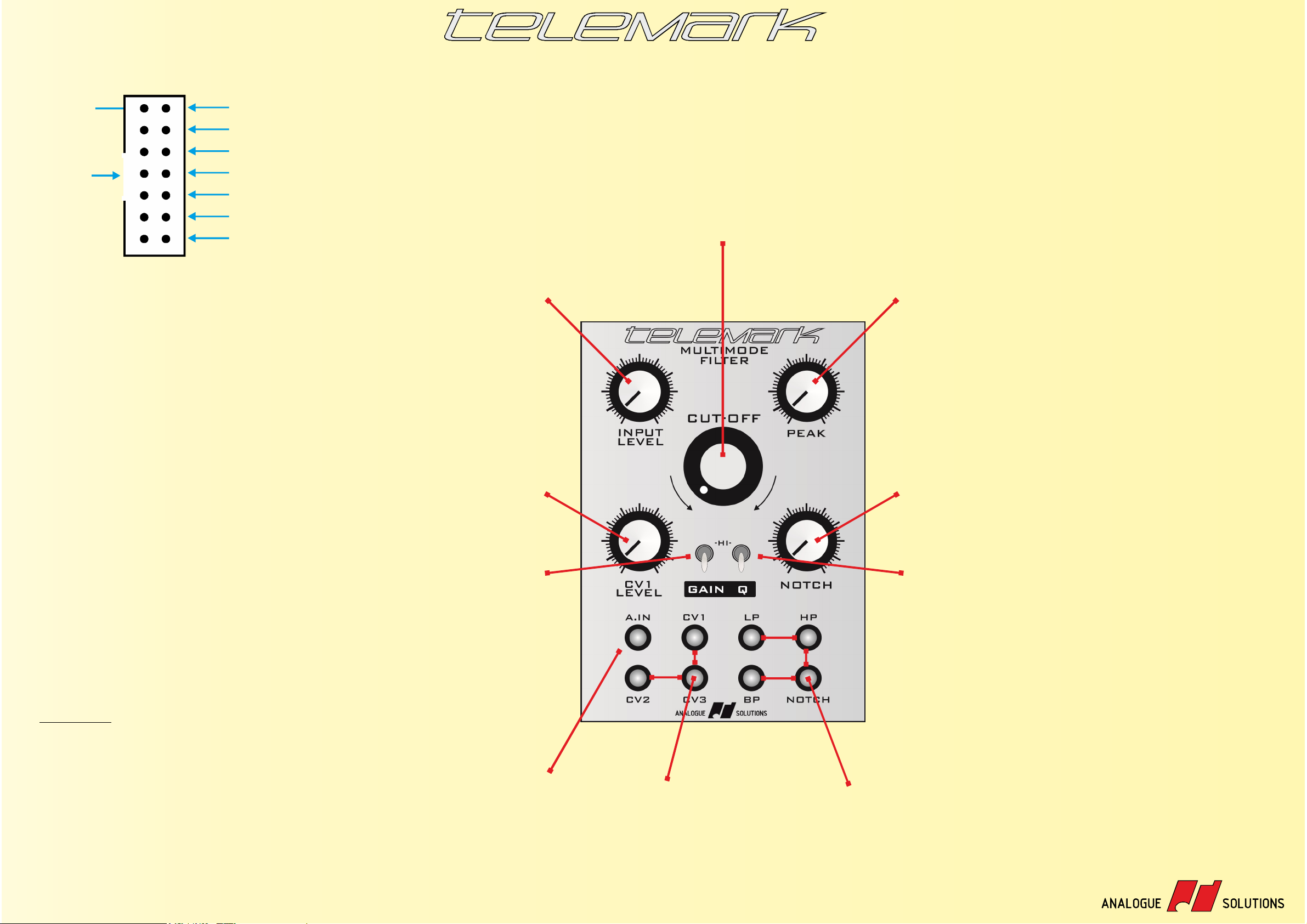
pin1
key
-12V
0V
0V
0V
+12V
n/a
MULTIMODE
FILTER
The Telemark multimode filter is based on the filter of the legendary Telemark semi-modular synthesizer. It's routes lie in
the original 1970s Oberheim , though it has developed a character of its own.SEM
The filter is a 12db/Octave multimode type. Multimode means there are more than one type of filter output. There are in
fact four: low pass, band pass, high pass and notch filter. Additionally, notch filter can be varied for an even wider range of
sounds.
Use of Gain and Q allow for even wider possibilities.
No special knowledge is required to use this filter. Just plug your audio in the left, and your audio out on the right.
Optionally (and recommended!) patch a control voltage in to give the sound movement.
The - control is used to CUT OFF
change the tone of the signal.
Mounting/Connection tips;
The supplied power cable is keyed.
That means it can only be fitted one way!
(Unless you use excessive force).
Pin one is at the top on our modules
(Doepfer fit their sockets upside-down).
AS Modules use a 14 pin 'boxed'
header on the .PCB
The two ends of the power cable are
different. Plug the 14pin socket end into
the Module power header.
Disconnect your case/ from the PSU
mains, then plug the larger 16pin socket
into your case's power supply.
The pin out on both plugs is the same.
Note: Physically disconnect your power
supply/case from the mains electricity.
Ensure you connect up the module
correctly!
Ensure it is screwed into the case.
Ensure no metal parts can short out the
solder joints on the rear.
Ensure your case is 100% functional
before fitting the module.
Most issues trace back to plugging in
the power cable in incorrectly.
Specification;
Width: 18HP
Depth: 35mm
Weight: 197g
Voltage: -/+12V
Power: +12V, 15mA / -12V, 28mA
Doepfer style power cable included.
Screws not included due to the wide variety of case
and screw types used.
To change the
input level of the
audio signal,
turn this.
Use this to alter
the level of the CV
signal coming in
socket 1.CV
When is on GAIN
(up) then the input
signal is boosted
and the filter input
can more easily
be over-driven.
Use this for a
dirtier sound.
When gain is on
the output level
will be higher.
A. is the audio input IN
to the filter. Typically
feed a into here.VCO
CV CV CV1 / 2 / 3 control voltage
inputs. feed s into here to CV
alter the cut-off frequency.
Typically use , or EG LFO
sequencer outputs.
CV1s range can be attenuated
with teh 1 control.CV LEVEL
Peak ( Resonance) - AKA
increase this to make the
sound more squiggy. As
it approaches maximum
you will get continuous
feedback & the sound
will be all like eeeeeeee.
Use to alter the NOTCH
balance between
Lowpass ( ) and LP
Highpass ( ) audio that HP
comes out of the
NOTCH socket.
Left is and right is .LP HP
When Q is on (up) then
the amount of feedback
possible using the PEAK
control is increased. The
resonance will be more
pronounced - and louder! More .EEEEEE
If you cross-mod the cutoff using audio from a
VCO, you will get a more
pronounced affect with
this turned on, and with
PEAK set to maximum.
These are the audio outputs from the
filter.
LP = Low Pass
BP = Band Pass
HP = High Pass
NOTCH = Well, notch.
All four can be used at once.
Or use two for S-T-E-R-E-O filtering.
www.analoguesolutions.com
 Loading...