

Page 1

Engineer-to-Engineer Note EE-210
a
Technical notes on using Analog Devices DSPs, processors and development tools
Contact our technical support at dsp.support@analog.com and at dsptools.support@analog.com
Or vi sit our o n-li ne r esou rces htt p:/ /www.analog.com/ee-notes and http://www.analog.com/processors
SDRAM Selection Guidelines and Configuration for ADI Processors
Contributed by Maikel Kokaly-Bannourah Rev 2 – August 13, 2004
Introduction
This EE-Note is intended to help the user select and configure a suitable Synchronous Dynamic Random
Access Memory (SDRAM) device to interface with Analog Devices Inc. (ADI) processors and DSPs.
The different factors involved in choosing the appropriate memory component depending on the Processor
or DSP used will be discussed in this document. Additionally, some programming examples on how to
configure the SDRAM controller will be shown.
Please note that, although the concepts explained throughout this note apply to all ADI processors and
DSPs that have an On-Chip SDRAM Controller, the programming examples described in this document
are based on the ADSP-TS201S TigerSHARC® and the ADSP-BF533 Blackfin® processors.
Table of Contents
Introduction........................................................................................................................................... 1
Table of Contents............................................................................................................................... 1
Listings ....................................................................................................................................................2
ADI Processors and DSPs ................................................................................................................ 3
SDRAM Specifications........................................................................................................................3
Choosing the appropriate SDRAM................................................................................................ 3
The ADSP-TS201S TigerSHARC Processor On-Chip SDRAM Controller..................... 3
SDRAM Controller Features .......................................................................................................3
Setting up the SDRAM Controller.........................................................................................4
SDRCON................................................................................................................................................. 4
The ADSP-BF533 Blackfin Processor On-Chip SDRAM Controller ............................8
SDRAM Controller Features .......................................................................................................8
Setting up the SDRAM Controller.........................................................................................9
EBIU_SDGCTL................................................................................................................................... 10
EBIU_SDBCTL................................................................................................................................... 14
EBIU_SDRRC...................................................................................................................................... 15
EBIU_SDSTAT................................................................................................................................... 16
Summary..................................................................................................................................................... 18
References..............................................................................................................................................20
Document History...............................................................................................................................20
Copyright 2004, Analog Devices, Inc. All rights reserved. Analog Devices assumes no responsibility for customer product design or the use or application of
customers’ products or for any infringements of patents or rights of others which may result from Analog Devices assistance. All trademarks and logos are property
of their respective holders. Information furnished by Analog Devices Applications and Development Tools Engineers is believed to be accurate and reliable, however
no responsibility is assumed by Analog Devices regarding technical accuracy and topicality of the content provided in Analog Devices’ Engineer-to-Engineer Notes.
Page 2

a
Listings
Figure 1. ADSP-TS201S SDRAM Control Register (SDRCON) ........................................5
Figure 2. ADSP-BF533 SDRAM EBIU_SDGCTL Register – Upper 16-bits ..............10
Figure 3. ADSP-BF533 SDRAM EBIU_SDGCTL Register – Lower 16-bits ..............11
Figure 4. ADSP-BF533 SDRAM Bank Control Register (EBIU_SDBCTL).................14
Figure 5. ADSP-BF533 EBIU_SDRRC Register...................................................................... 15
Figure 6. ADSP-BF533 SDRAM Status Register (EBIU_SDSTAT)............................... 16
Table 1. ADSP-TS201S TigerSHARC Processor and SDRAMs compatibility......... 4
Table 2. SDRAM “A” CAS Latency................................................................................................ 5
Table 3. SDRAM “A” Specifications ........................................................................................ 6
Table 4. Relevant SDRAM “A” Timing Specifications.................................................. 7
Table 5. ADSP-BF533 Blackfin Processor and SDRAMs compatibility ................9
Table 6. SDRAM “D” CAS Latency.............................................................................................. 11
Table 7. Relevant SDRAM “D” Timing Specifications................................................ 12
Table 8. SDRAM “D” Specifications ...................................................................................... 15
Table 9. TigerSHARC Processors with On-Chip SDRAM Controller...................... 19
Table 10. Blackfin Processors with On-Chip SDRAM Controller........................ 19
Table 11. SHARC DSPs with On-Chip SDRAM Controller.............................................. 20
Code 1. SDRCON Settings using header file defts201.h........................................... 7
Code 2. SDRCON Settings without the use of header files.................................... 8
Code 3. SDRAM Control Registers Settings using header file defBF532.h 17
Code 4. SDRAM Control Registers Settings without header files................... 18
SDRAM Selection Guidelines and Configuration for ADI Processors (EE-210) Page 2 of 20
Page 3

a
ADI Processors and DSPs
Several Analog Devices processors and DSPs
have been designed with an on-chip SDRAM
controller:
• The ADSP-21065L and ADSP-21161N
SHARC DSPs.
• The ADSP-TS101S, ADSP-TS201S, ADSP-
TS202S and ADSP-TS203S TigerSHARC
processors.
• The ADSP-BF531, ADSP-BF532, ADSP-
BF533 and ADSP-BF535 Blackfin
processors.
Having an On-Chip SDRAM Controller allows
to gluelessly interface to SDRAM memory
devices without the necessity of incorporating
additional components to the system, resulting in
a cost-effective solution.
SDRAM Specifications
There are several factors that need to be
considered when selecting an SDRAM device to
interface with ADI’s processors or DSPs, which
are common across all families:
• Supported operating voltage
• Maximum supported operating frequency
• Maximum supported memory
• I/O size and number of banks
• Column Address Strobe (CAS) latency
• Refresh rate
• Burst length
• Page size
• Initialization sequence
All these characteristics are defined in the
SDRAM device datasheet and must meet the
specifications of the on-chip SDRAM controller
of the processor being used in order to be able to
gluelessly interface to it.
Choosing the appropriate SDRAM
As an example, let’s examine the ADSP-TS201S
TigerSHARC and the ADSP-BF533 Blackfin
processors and their compatibility with different
SDRAM devices.
The ADSP-TS201S TigerSHARC
Processor On-Chip SDRAM
Controller
Before an SDRAM device can be selected, the
user needs to understand the features and
specifications of the chosen processor.
SDRAM Controller Features
With the factors previously explained in mind,
these are the relevant ADSP-TS201S processor
on-chip SDRAM controller characteristics for
choosing the appropriate memory device:
• Supported operating Voltage
o 3.3 and 2.5 V
• Maximum supported operating Frequency
o 125 MHz
• Maximum supported memory
o 256 Mbytes (64 M x 32 bits or
32 M x 64 bits) per external SDRAM
bank
• Number of internal SDRAM banks
o 2 or 4 banks.
• Column Address Strobe (CAS) latency
o Programmable value: 1 to 3 system clock
cycles (SCLK)
• Refresh rate
o Programmable value: 32 to 64 ms.
• Burst Length
o Full page burst
• Page size
o Programmable value to: 256, 512 or 1024
words.
• Initialization sequence
o Programmable sequence: MRSÖREF, or
REFÖMRS.
SDRAM Selection Guidelines and Configuration for ADI Processors (EE-210) Page 3 of 20
Page 4
a
For the aid of this example, devices A and B
have been selected. Are these two SDRAM
devices compatible with the ADSP-TS201S
SDRAM
Features
Voltage
Max. Frequency
Max. Mem. Size
Supported I/O
Number of
SDRAM Banks
CAS Latency
Refresh Rate
Burst Length
ADSP-TS201S SDRAM
Controller
2.5 or 3.3 V 3.3 V
125 MHz 143/166 MHz
64 Mx32 or 32 Mx64
(256 Mbytes) per external
SDRAM bank
x32, x64
2 or 4 banks 4 banks
1 to 3 cycles 1 to 3 cycles
32 and 64 ms 64 ms
Full-page burst
TigerSHARC Processor? Let’s look at the
different specifications to be met:
SDRAM “A”
1 Meg x 32 x 4
banks
16 Mbytes
x32
1,2,4,8 or
Full-page
OK
9
9
9
9
9
9
9
9
SDRAM “B”
4 Meg x 32 x 2
banks
3.3 V
100/133 MHz
32 Mbytes
x32
2 banks
1 to 3 cycles
64 ms
1
OK
9
9
9
9
9
9
9
8
Page Size
Init. Sequence
Table 1. ADSP-TS201S TigerSHARC Processor and SDRAMs compatibility
As it can be seen from the table above, device B
does not meet all specifications: it only supports
burst length of one (and not full page burst) and
its page size is 2048 words (which is bigger than
the maximum supported page size of 1024
words).
On the other side, it can be seen that device A
meets all requirements, and therefore, it can be
properly interfaced to the ADSP-TS201S
TigerSHARC Processor.
Setting up the SDRAM Controller
Now that a compatible SDRAM device has been
selected (SDRAM A), the next step is to properly
configure the SDRAM control register
256, 512, and 1024 256
MRSÖREF or REFÖMRS REFÖMRS
(SDRCON) according to the memory
specifications given in Table 1.
SDRCON
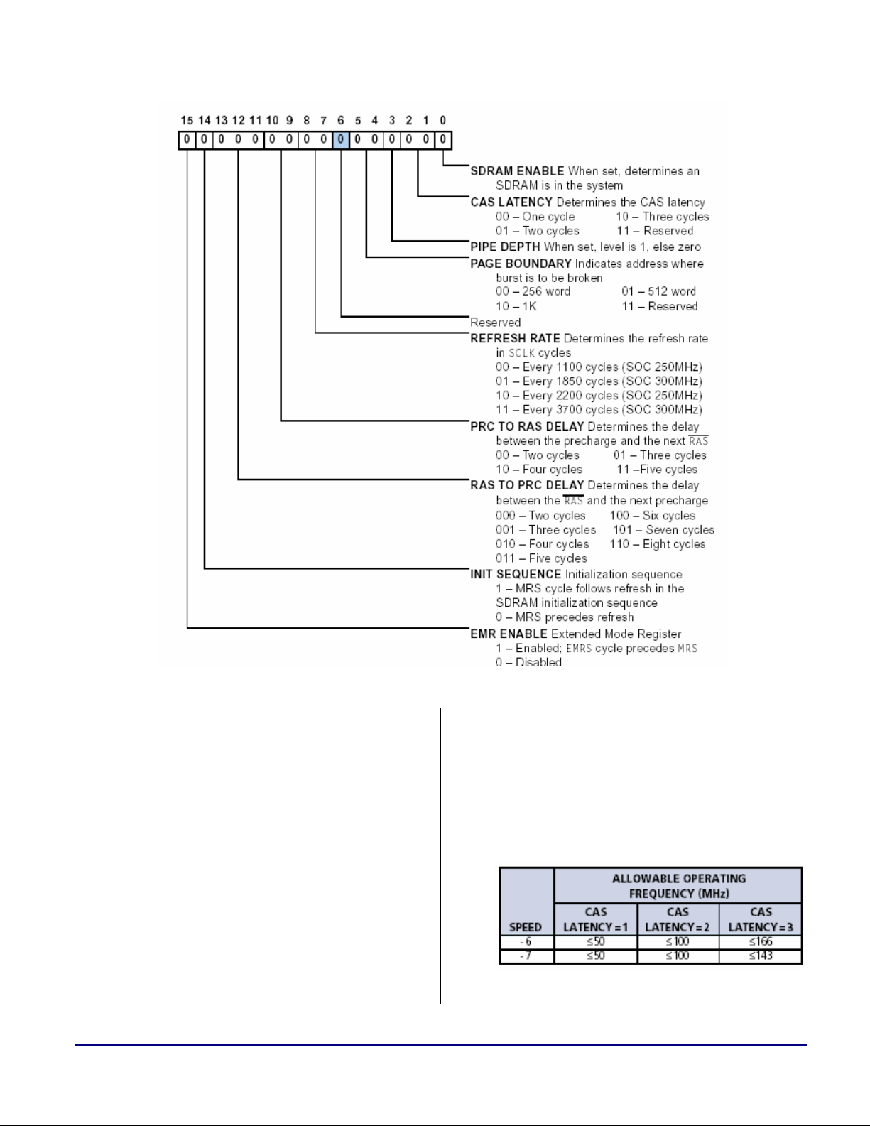
The initial value of the SDRCON register after
reset is zero, meaning that the SDRAM is
disabled. The bit descriptions for this register are
shown in Figure 1. Note that although this is a
32-bit register, only the lower 16-bits are shown.
The upper 16-bits are reserved and should
always be set to zero.
For more details, please refer to SDRAM
Interface chapter of the ADSP-TS201
TigerSHARC Processor Hardware Reference.
9
9
2048
MRSÖREF
8
9
SDRAM Selection Guidelines and Configuration for ADI Processors (EE-210) Page 4 of 20
Page 5
a
Figure 1. ADSP-TS201S SDRAM Control Register (SDRCON)
So how do we correctly set up the SDRAM
Control register (SDRCON)? Let’s have a look
at a typical SDRAM device datasheet to
determine the settings for the different bits:
• SDRAM ENABLE. This bit must be set
when SDRAM is present in the system
(SDRCON_ENBL).
To use the above bit definition
L
SDRAM Selection Guidelines and Configuration for ADI Processors (EE-210) Page 5 of 20
(SDRCON_ENBL), the file defTS201.h
should be included in the source code
(see Code 1 ). This file comes with the
VisualDSP++™ 32-bit Tools and can be
found in the directory:
• CAS LATENCY. This parameter specifies
Table 2. SDRAM “A” CAS Latency
C:\...\AnalogDevices\VisualDSP\TS\include.
the delay between a read command and the
time data becomes available. It does not
apply to write accesses. CAS Latency is
generally specified in the datasheet as shown
in Table 2.
Page 6

Assuming the external port runs with a
100MHz system clock (SCLK), the selected
CAS LATENCY is 2 (SDRCON_CLAT2).
Note that, as specified in Table 1, the
maximum supported SCLK frequency by the
ADSP-TS201S is 125 MHz. The selected
frequency for this example, 100 MHz,
corresponds to the default value of the
ADSP-TS201S EZ-KIT Lite™.
Some SDRAM timing specifications
L
• PIPE DEPTH. In systems where several
• PAGE BOUNDARY. These bits define the
(CL, tRAS, tRP, etc) may vary depending
on the speed grade of the SDRAM being
used.
Settings in this particular example are
optimized for a dedicated operating
frequency (100 MHz) and speed grade
part (-6). Variations in the clock
frequency and/or speed grade of the
SDRAM device also require modifying
the parameter settings.
SDRAMs are used in parallel, and external
buffers are needed, this bit should be
enabled.
This is valid if the nominal capacitive pin
loading is exceeded (30 pF/pin). In this
particular example (ADSP-TS201S EZ-KIT
Lite), there are only two SDRAMs where no
buffering of the signals is needed (SDRAM
pin capacitance 2x5 pF+10 pF (PCB) ≈
20 pF). Therefore, this bit should be cleared
(SDRCON_PIPE1).
page size, in number of words, of the
SDRAM’s banks. This number corresponds
to the number of addressable columns.
Table 3. SDRAM “A” Specifications
As it can bee seen in Table 3, the maximum
number of addressable columns is 256 (A0-
7). Thus, the page size should be configured
to 256 (SDRCON_PG256).
• REFRESH RATE. These bits select the
refresh counter to coordinate the Processor’s
SOC clock rate (SOCCLK) with the SDRAM
device’s required refresh rate.
The refresh count is provided in Table 3 as
4 K, and is also generally listed under the
SDRAM features list as:
64 ms, 4,096-cycle refresh (15,6 µs/row)
With this in mind, the refresh rate is
calculated as follows:
⎛
SOCCLKCycles
⎜
⎝
Where: SOCCLK = 250 MHz (default
ADSP-TS201S EZ-KIT Lite value)
tREF = SDRAM refresh period
Rows = number of row addresses
Therefore,
Refresh rate = 250 MHz × 15,6 µs
= 3900 cycles
In order to be able to guarantee that this
number is met, a refresh rate equal to or
smaller than 3900 cycles should be selected.
In this case, and since the processor’s
controller supports up to 3700 cycles only,
this should be the selected refresh rate
(SDRCON_REF3700).
tREF
⋅=
Rows
a
⎞
⎟
⎠
SDRAM Selection Guidelines and Configuration for ADI Processors (EE-210) Page 6 of 20
• PRC TO RAS DELAY. This parameter
determines the Precharge to RAS delay,
which is typically given in the datasheet as
tRP.
Page 7

a
Table 4 illustrates some of the SDRAM
timing specifications that can be found in the
datasheet. As it can be seen, the device with
speed grade -6 has tRPmin = 18ns. At
Table 4. Relevant SDRAM “A” Timing Specifications
• RAS TO PRC DELAY: This parameter
determines the RAS to Precharge delay,
which is typically given in the datasheet as
100 MHz, this gives a minimum time of
1.8 cycles. Therefore, tRP should be set to
2 cycles (SDRCON_PC2RAS2).
This means that the device minimum
requirements after power up are:
PRE + 2×Autorefresh + MRS
tRAS.
When setting this bit to 1 the controller
As shown in Table 4, this SDRAM device
issues the following sequence of commands:
has tRASmin = 42 ns. At 100 MHz, this gives
a minimum time of 4.2 cycles. Therefore,
tRAS should be set to 5 cycles
(SDRCON_RAS2PC5).
• INIT SEQUENCE: This bit determines the
SDRAM initialization sequence at power up.
From the Initialization section in the
datasheet:
“[…] Once the 100µs delay has been
satisfied with at least one COMMAND
INHIBIT or NOP command having been
PRE + 8×Autorefresh + MRS
This meets the power-up timing
specifications of the selected SDRAM.
Therefore, this bit should be set
(SDRCON_INIT).
• EMR ENABLE. This bit should only be set
when interfacing to Low-Power SDRAM
(2.5 Volts) devices. Otherwise, this bit
should remain cleared.
From the datasheet Features list:
applied, a PRECHARGE command should be
applied.
[…] Once in the idle state, two AUTO
REFRESH cycles must be performed. After
the AUTO REFRESH cycles are complete,
the SDRAM is ready for Mode Register
programming.”
#include <defts201.h>
xr0 = SDRCON_INIT | SDRCON_RAS2PC5 | SDRCON_PC2RAS2 |
SDRCON_REF3700 | SDRCON_PG256 | SDRCON_CLAT2 | SDRCON_ENBL;;
SDRCON = xr0;;
Single +3.3 V ±0.3 V power supply
Therefore, since this is a standard SDRAM
device, this bit should be cleared
(SDRCON_EMRS).
Thus, with the above settings in mind, the
SDRCON register should be set to:
Code 1. SDRCON Settings using header file defts201.h
SDRAM Selection Guidelines and Configuration for ADI Processors (EE-210) Page 7 of 20
Page 8

a
As it can be seen in Code 1, any of the SDRCON
bits that should be cleared (i.e. PIPE DEPTH and
EMR ENABLE) are simply ignored and not
In the case were the bit definitions
(“defts201.h”) were not used, the SDRCON
register should be programmed as follows:
included in the bit settings above (remember that
by default SDRCON = 0x0000 0000).
j11 = j31 + 0x00005983;;
SDRCON = j11;; // 0000000000000000 0 1 011 00 11 0 00 0 01 1
// |---RESERVED---| | | | | | | | | | |
// | | | | | | | | | |- SDRAM Enabled
// | | | | | | | | |--- CAS LATENCY = 2
// | | | | | | | |------ PIPE DEPTH = 0
// | | | | | | |-------- PAGE BOUNDARY = 256
// | | | | | |----------- Reserved
// | | | | |------------- REFRESH RATE = 3700
// | | | |---------------- tRP = 2
// | | |------------------- tRAS = 5
// | |----------------------- INIT SEQUENCE PRE+MRS
// |------------------------- EMR DISABLED
Code 2. SDRCON Settings without the use of header files
After SDRCON is properly configured with the
value previously discussed, the controller will
perform a Mode Register Set (MRS) command,
which initializes the external memory device.
Please note that during this MRS command,
some of the SDRAM parameters, which are not
programmable in SDRCON, are initialized. This
is the case for the Burst Length and Type, which
are hardwired to full page burst and sequential.
At this point, the user can safely start accessing
the SDRAM.
The ADSP-BF533 Blackfin
Processor On-Chip SDRAM
Controller
Like in the previous example, before an SDRAM
device can be selected, the user needs to
understand the features and specifications of the
chosen Processor.
Note that, although this section refers to the
ADSP-BF533, the same concepts apply for the
ADSP-BF532 and ADSP-BF531, since the
SDRAM Controller (SDC) functionality is the
same for all three parts.
SDRAM Controller Features
These are the relevant ADSP-BF533 Processor
on-chip SDRAM controller characteristics for
choosing the appropriate memory device:
• Supported operating Voltage
o 3.3 and 2.5 V
• Maximum supported operating Frequency
o 133 MHz
• Maximum supported memory
o 128 Mbytes (64 M x 16 bits)
• Number of banks
SDRAM Selection Guidelines and Configuration for ADI Processors (EE-210) Page 8 of 20
Page 9

a
o 4 banks.
• Column Address Strobe (CAS) latency
o Programmable value: 2 or 3 system clock
cycles (SCLK)
• Refresh rate
o Programmable value: 1 to 4095 system
clock cycles (SCLK).
• Burst Length
o Burst length of 1
• Page size
SDRAM
Features
Voltage
Max. Frequency
Max. Mem. Size
ADSP-BF533 SDRAM
Controller
2.5 and 3.3 V 3.3 V
133 MHz 143/166 MHz
64 M x 16 (128 Mbytes)
o Programmable value to:
512, 1024 2048 or 4096 bytes.
• Initialization sequence
o Programmable sequence:
MRSÖREF, or REFÖMRS.
For the aid of this example, devices C and D
have been selected.
Are these two SDRAM devices compatible with
the ADSP-BF533 Blackfin Processor? Let’s look
at the different specifications to be met:
SDRAM “C”
4 Meg x 16 x 2
banks
16 Mbytes
OK
9
9
9
SDRAM “D”
4 Meg x 16 x 4
banks
3.3 V
100/143 MHz
32 Mbytes
OK
9
9
9
Supported I/O
Number of
SDRAM Banks
CAS Latency
Refresh Rate
Burst Length
Page Size
(bytes)
Init. Sequence
Table 5. ADSP-BF533 Blackfin Processor and SDRAMs compatibility
As it can be seen from the table above, device C
does not meet all specifications: it has 2 banks (4
banks supported only) and it supports full page
burst (burst length of one supported only).
On the other side, it can be seen that device D
meets all requirements, and therefore, it can be
properly interfaced to the ADSP-BF533 Blackfin
processor.
Programmable (SDRRC)
512, 1024, 2048 and 4096 2048
MRSÖREF or REFÖMRS REFÖMRS
x16 x16 9 x16
4 banks 2 banks
2 or 3 cycles 1 to 3 cycles
64 ms
1 Full-page
Setting up the SDRAM Controller
Now that a compatible SDRAM device has been
selected (SDRAM D), the next step is to properly
configure the different SDRAM control registers
according to the memory specifications given in
Table 5.
After a processor’s hardware or software reset,
the SDC clocks are enabled. However, the SDC
must be configured and initialized.
8
9
9
8
9
9
4 banks
1 to 3 cycles
64 ms
1,2,4,8 or Full-page
1024
MRSÖREF
9
9
9
9
9
9
9
SDRAM Selection Guidelines and Configuration for ADI Processors (EE-210) Page 9 of 20
Page 10

In order to set up the SDC and start the SDRAM
power-up sequence, the SDRAM Refresh Rate
Control register (EBIU_SDRRC), the SDRAM
Memory Bank Control register
(EBIU_SDBCTL), and SDRAM Memory Global
Control register (EBIU_SDGCTL) must be
written, and a transfer must be started to
SDRAM address space.
The following sections will briefly describe each
one of the registers mentioned above as well as
their bit descriptions.
a
EBIU_SDGCTL
The SDRAM Memory Global Control Register
(SDGCTL) includes all programmable
parameters associated with the SDRAM access
timing and configuration.
The bit descriptions for EBIU_SDGCTL are
shown in Figure 2 and Figure 3.
Figure 2. ADSP-BF533 SDRAM EBIU_SDGCTL Register – Upper 16-bits
SDRAM Selection Guidelines and Configuration for ADI Processors (EE-210) Page 10 of 20
Page 11

Figure 3. ADSP-BF533 SDRAM EBIU_SDGCTL Register – Lower 16-bits
a
So how do we correctly set up the SDRAM
Global Control register (EBIU_SDGCTL)? Let’s
have a look at a typical SDRAM device
datasheet to determine the settings for the
different bits:
• SCTLE. This bit must be set for SDC
operation and is enabled by default at reset
(SCTLE).
To use the above bit definition (SCTLE),
L
• CL. This parameter specifies the delay
Table 6. SDRAM “D” CAS Latency
SDRAM Selection Guidelines and Configuration for ADI Processors (EE-210) Page 11 of 20
the file defBF533.h should be included
in the source code (see Code 3). This file
comes with the VisualDSP++ 16-bit
Tools and can be found in the directory:
C:\..\AnalogDevices\VisualDSP\Blackfin\include
between a read command and the time data
becomes available. It does not apply to write
accesses. CAS Latency is generally specified
in the datasheet as shown in Table 6.
Assuming the external port runs with a
54MHz system clock (SCLK), the selected
CAS LATENCY is 2 (CL_2).
Note that, as specified in Table 5, the
maximum supported SCLK frequency by the
ADSP-BF533 is 133 MHz. The selected
frequency for this example, 54 MHz,
corresponds to the default value of the
ADSP-BF533 EZ-KIT Lite.
Some SDRAM timing specifications
L
• PASR. When EMREN (Extended Mode
• TRAS. This parameter determines the RAS
(CL, tRAS, tRP, etc) may vary depending
on the speed grade of the SDRAM being
used.
Settings in this particular example are
optimized for a dedicated operating
frequency (54 MHz) and speed grade
part (-75). Variations in the clock
frequency and/or speed grade of the
SDRAM device also require modifying
the parameter settings.
Register Enable) is set, the PASR bits (in
combination with the TCSR bit) control the
value written to the Extended Mode Register.
This only applies for mobile low-power
SDRAMs (2.5 V). Since SDRAM “D” is
standard LVTTL (3.3 V), these bits can be
ignored (PASR_X).
to Precharge delay, which is typically given
in the datasheet as tRAS.
Page 12

a
Table 7 illustrates some of the SDRAM
timing specifications that can be found in the
datasheet. As it can be seen, this SDRAM
device (speed grade -75) has tRASmin =
44 ns. At 54 MHz, this gives a minimum time
of 2.38 cycles. Therefore, tRAS should be set
to 3 cycles (TRAS_3).
• TRP. This parameter determines the
Precharge to RAS delay, which is typically
given in the datasheet as tRP.
As shown in Table 7, the device with speed
grade -75 has tRPmin = 20ns. At 54 MHz,
this gives a minimum time of 1.08 cycles.
Therefore, tRP should be set to 2 cycles
(TRP_2).
• TRCD. This parameter determines the delay
between bank activation and the first
read/write from/to SDRAM. It is typically
given as tRCD.
From Table 7, the device with speed grade 75 has tRCDmin = 20 ns. At 54 MHz, this
gives a minimum time of 1.08 cycles.
Therefore, tRCD should be set to 2 cycles
(TRCD_2).
• TWR. This parameter determines the delay
between a write and a Precharge command. It
is typically given as tWR.
As shown in Table 7, the device with speed
grade -75 has tWRmin = 1CLK+7.5 ns =
26 ns. At 54 MHz, this gives a minimum time
of 1.4 cycles. Therefore, tWR should be set to
2 cycles (TRW_2).
Table 7. Relevant SDRAM “D” Timing Specifications
specifications for tXSR, tRAS or tRP
should be increased by 1. Typically,
increasing tRAS gives better
performance, since it is used less often
by the controller.
optionally delays the power-up start sequence
L
The value of tXSR is equal to tRAS +
tRP. This is fixed by the controller.
Thus, the user must make sure that the
specification for tXSR is met when
selecting the values for tRAS and tRP.
If tRAS + tRP does not meet the
• PUPSD. The Power-up Start Delay bit
SDRAM Selection Guidelines and Configuration for ADI Processors (EE-210) Page 12 of 20
Page 13

a
for 15 SCLK cycles. This is useful for
multiprocessing systems sharing an external
SDRAM.
Since this example is based on the ADSPBF533 EZ-KIT Lite (single processor
system), the setting for this bit does not apply
(PUPSD).
• PSM. This bit determines the SDRAM
power-up sequence. From the Initialization
section in the datasheet:
“[…] Once the 100 µs delay has been
satisfied with at least one COMMAND
INHIBIT or NOP command having been
applied, a PRECHARGE command should be
applied.
[…] Once in the idle state, two AUTO
REFRESH cycles must be performed. After
the AUTO REFRESH cycles are complete,
the SDRAM is ready for Mode Register
programming.”
This means that the device minimum
requirements after power up are:
PRE + 2×Autorefresh + MRS
When clearing this bit (=0) the controller
issues the following sequence of commands:
PRE + 8×Autorefresh + MRS
This meets the power up timing
specifications of the selected SDRAM
device. Therefore, this bit should be cleared
(PSM).
• PSSE. The Power-up Sequence Start enable
bit must be set to 1 to enable the SDRAM
power-up sequence (PSSE).
A read or write access must be done to
L
enable SDRAM address space in order
to have the external bus granted to the
SDC so that the SDRAM power-up
sequence may occur.
• SRFS. When setting the Self-Refresh bit
(=1), the SDC completes any active transfers
and then puts the SDRAM into self-refresh
mode. The next access to SDRAM will take
the device out of self-refresh mode,
performing the transfer to or from SDRAM.
This mode is used to reduce the application’s
power consumption to a minimum when the
SDRAM is not being accesses for an
extended period of time. This does not apply
for this example, therefore this bit should be
cleared (SRFS).
• EBUFE. In systems where several SDRAM
devices are used in parallel, and external
buffers are needed, this bit should be enabled
(=1).
This is valid if the nominal capacitive pin
loading is exceeded (50 pF/pin) In this
particular example (ADSP-BF533 EZ-KIT
Lite), there is only one SDRAM where no
buffering of the signals is needed (SDRAM
pin capacitance 5 pF+10 pF (PCB) ≈ 15 pF).
Therefore, this bit should be cleared
(EBUFE).
• FBBRW. The Fast Back-to-Back Read to
Write bit enables SDRAM read followed by
write to occur on consecutive cycles. In many
systems, this is not possible because the
turnoff time of the SDRAM data pins is too
long. When this bit is 0, a clock cycle is
inserted between read accesses followed by
write accesses.
For this example, an extra cycle is added
between read and write transactions,
therefore this bit should be cleared
(FBBRW).
• EMREN. This bit should only be set when
interfacing to mobile low-power SDRAM
(2.5 V) devices. Otherwise, this bit should
remain cleared.
SDRAM Selection Guidelines and Configuration for ADI Processors (EE-210) Page 13 of 20
Page 14
a
From the SDRAM “D” datasheet Features
list:
Single +3.3 V ±0.3 V power supply
Therefore, since this is a standard LVTTL
(3.3 V) SDRAM device, this bit should be
cleared. (EMREN)
• TCSR. When EMREN (Extended Mode
Register Enable) is set, the TCSR bit (in
combination with the PASR bits) controls the
value written to the Extended Mode Register.
This only applies for mobile low-power
SDRAMs (2.5 V). Since SDRAM “D” is
standard LVTTL (3.3 V), this bit can be
ignored (TCSR).
• CDDBG. The Control Disable During Bus
Grant bit is used to enable or disable the
SDRAM control signals when the external
memory interface is granted to an external
controller.
Otherwise, these signals continue to be
driven during grant.
In this example, the control signals are not
shared with any external controller, therefore
this bit should be cleared (CDDBG).
A programming example of the EBIU_SDGCTL
SDRAM control register is shown at the end of
this section (Code 3).
ALL reserved bits in this register must
L
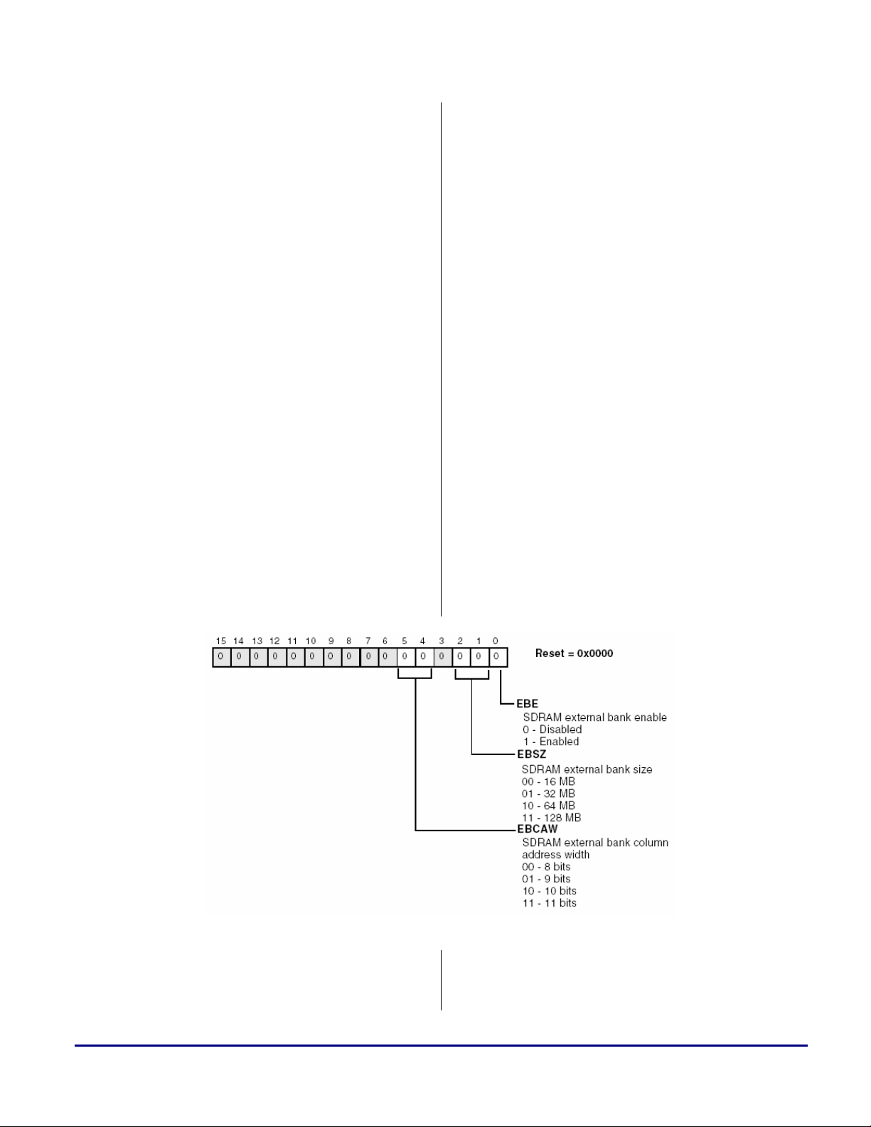
EBIU_SDBCTL
The SDRAM Memory Bank Control Register
includes external bank specific programmable
parameters of the SDRAM. This register is 16-bit
wide and uses the access timing parameters
defined in the EBIU_SDGCTL register.
The bit descriptions for EBIU_SDBCTL are
shown in Figure 4.
always be written with zeros.
If this bit is set (=1), the control signals are
three-stated when bus grant is active.
Figure 4. ADSP-BF533 SDRAM Bank Control Register (EBIU_SDBCTL)
• EBE. This bit is used to enable or disable the
external SDRAM bank. This bit must be
enabled when accessing the external
SDRAM bank. If disabled, any access to
SDRAM address space generates an internal
SDRAM Selection Guidelines and Configuration for ADI Processors (EE-210) Page 14 of 20
Page 15

error. Therefore, this bit should be set to 1
(EBE).
• EBSZ. This bit determines the SDRAM
External Bank Size according to the density
and I/O configuration of the SDRAM device
used.
In this example, the selected SDRAM
(device “D” -Table 8) is: 16 M x 16.
Therefore:
EBSZ = 16 M × 16 = 256 Mbit = 32 Mbyte
Thus, the SDRAM External Bank Size
should be set to 32 Mbyte (EBSZ_32).
For more details on the supported EBSZ
encodings refer to the SDRAM
Configurations Supported section of the
SDRAM Controller in the External Bus
Interface Unit chapter of the ADSP-BF533
Blackfin Processor Hardware Reference.
Although the smallest supported
L
• EBCAW. These bits determine the SDRAM
SDRAM external bank size is 16Mbytes,
smaller devices can also be interfaced to
the ADSP-BF533.
In this case, the external bank size in
SDBCTL should be configured to
16 Mbyte (EBSZ_16), but the user’s
code should not access any SDRAM
address outside the physical memory
size of the SDRAM being used.
Exceeding this range will result in
looping back to the first SDRAM
memory location corrupting existing
data.
external bank column address width. As
previously explained (Table 5) page sizes of
512 bytes, 1 Kbyte, 2 Kbytes and 4 Kbytes
are supported.
Table 8. SDRAM “D” Specifications
In order to be able to calculate the page size,
the following formula is used:
16-bit SDRAM banks: page size = 2
where CAW is the column address width of
the SDRAM, plus 1 because the SDRAM
bank is 16 bits wide.
As shown in Table 8, the column address
width for device “D” is 512 bits (A0-A8).
Therefore, EBCAW = 9 bits (01)
(EBCAW_9).
Thus:
Page size = 2
A programming example of the EBIU_SDBCTL
SDRAM control register is shown at the end of
this section (Code 3).
EBIU_SDRRC
The SDRAM Refresh Rate Control Register
(EBIU_SDRRC) provides a flexible mechanism
for specifying the Auto-Refresh timing.
Since the clock supplied to the SDRAM can
vary, the SDC provides a programmable refresh
counter which has a period based on the value
programmed into the RDIV field of this register
that coordinates the supplied clock rate with the
SDRAM device’s required refresh rate.
The bit descriptions for EBIU_SDRRC are
shown in Figure 5.
(9+1)
= 1024 = 1 Kbyte
a
(CAW+1)
Figure 5. ADSP-BF533 EBIU_SDRRC Register
SDRAM Selection Guidelines and Configuration for ADI Processors (EE-210) Page 15 of 20
Page 16

a
• RDIV. The value to be written to this register
can be calculated using the following
formula:
RDIV =((f
Where: f
x tREF)/NRA)-(tRAS + tRP)
SCLK
= SDRAM clock frequency
SCLK
tREF = SDRAM refresh period
NRA = number of row addresses
tRAS = tRAS in clock cycles
tRP = tRP in clock cycles
For this example, the SCLK frequency is
54 MHz. The refresh count and number of
rows are provided in Table 8 as 8K cycle
period and 8 K rows. The refresh period is
also generally listed under the SDRAM
features list as:
64 ms, 8,192-cycle refresh
tRAS and tRP are defined in
EBIU_SDGCTL as 3 and 2 cycles
respectively. With this in mind, the value for
RDIV is calculated as follows:
RDIV =((54 MHz x 64 ms)/8192) - (3+2) =
416.87 ≈ 416 = 0x1A0 clock cycles
Therefore, RDIV must be programmed to
0x1A0 (hex).
A programming example of the EBIU_SDRRC
SDRAM control register is shown at the end of
this section (Code 3).
EBIU_SDSTAT
In addition to the previously mentioned SDRAM
control registers, an SDRAM Status Register
(EBIU_SDSTAT) provides information on the
state of the SDRAM controller, which can be
used to determine when it is safe to alter the
SDRAM controller parameters or simply as a
debug aid.
The bit descriptions for EBIU_SDSTAT are
shown in Figure 6.
Figure 6. ADSP-BF533 SDRAM Status Register (EBIU_SDSTAT)
For more details on the SDRAM control
registers, refer to the SDRAM Controller in
the External Bus Interface Unit chapter of the
ADSP-BF533 Blackfin Processor Hardware
Reference.
With the settings for the EBIU_SDGCTL,
EBIU_SDBCTL and EBIU_SDRRC registers
previously discussed, the example code for the
ADSP-BF533 EZ-KIT Lite would look as
follows:
SDRAM Selection Guidelines and Configuration for ADI Processors (EE-210) Page 16 of 20
Page 17

#include <defbf532.h>
//SDRAM Refresh Rate Control Register
P0.L = lo(EBIU_SDRRC); P0.H = hi(EBIU_SDRRC);
R0 = 0x01A0 (z);
w[P0] = R0;
//SDRAM Memory Bank Control Register
P0.L = lo(EBIU_SDBCTL); P0.H = hi(EBIU_SDBCTL);
R0 = EBE | EBSZ_32 | EBCAW_9 (z);
w[P0] = R0;
//SDRAM Memory Global Control Register
P0.L = lo(EBIU_SDGCTL); P0.H = hi(EBIU_SDGCTL);
R0 = 0x0; [P0] = R0;
R0.L = SCTLE | CL_2 | TRAS_3 | TRP_2;
R0.H = TRCD_2| TWR_2 | PSSE;
[P0] = R0;
Code 3. SDRAM Control Registers Settings using header file defBF532.h
a
As it can be seen in Code 3, any of the SDRAM
control register bits that should be cleared (i.e.
PSM, PUPSD, etc.) are simply ignored and not
In the case where these bit definitions were not
used, the SDRAM control registers should be
programmed as follows:
included in the bit settings above (note that the
registers are zeroed before initialization).
//SDRAM Refresh Rate Control Register
P0.L = lo(EBIU_SDRRC);
P0.H = hi(EBIU_SDRRC);
R0 = 0x01A0 (z);
w[P0] = R0;
//SDRAM Memory Bank Control Register
P0.L = lo(EBIU_SDBCTL);
P0.H = hi(EBIU_SDBCTL);
R0.L = 0x0013; // 0000 0000 00 01 0 01 1
// |-RESERVED-| | | | |- SDRAM External Bank Enabled
// | | | -- Ext.Bank Size = 32Mbyte
// | |------ RESERVED
// |-------- Ext.Bank CAW = 9 bits
R0.H = 0x0000;
[P0] = R0;
//SDRAM Memory Global Control Register
P0.L = lo(EBIU_SDGCTL);
P0.H = hi(EBIU_SDGCTL);
R0.L = 0x10C9; // 0 0 000 0 0000 00 10 0 1
// | | | | | | | | |- SDRAM Control Enabled
// | | | | | | | |--- RESERVED
// | | | | | | |----- CAS LATENCY = 2
// | | | | | |-------- PASR = IRRELEVANT
// | | | | |----------- TRAS = 3 cycles
// | | | |---------------- RESERVED
// | | |------------------ TRP = 2 cycles
// | |---------------------- RESERVED
// |------------------------ TRCD[1] = 2 cycles
R0.H = 0x0091; // 0 0 0 0 0 0 0 0 1 0 0 10 0 01
SDRAM Selection Guidelines and Configuration for ADI Processors (EE-210) Page 17 of 20
Page 18

// | | | | | | | | | | | | | |- TRCD[2:1] = 2 cycles
// | | | | | | | | | | | | |---- RESERVED
// | | | | | | | | | | | |------ TWR = 2 cycles
// | | | | | | | | | | |--------- PUPSD = IRRELEVANT
// | | | | | | | | | |----------- PSM = PRE+REF+MRS
// | | | | | | | | |------------- PSSE = enabled
// | | | | | | | |--------------- SRFS = disabled
// | | | | | | |----------------- EBUFE = no ext. buffering
// | | | | | |------------------- FBBRW = disabled
// | | | | |--------------------- RESERVED
// | | | |----------------------- EMREN = IRRELEVANT
// | | |------------------------- TCSR = IRRELEVANT
// | |--------------------------- CDDBG = IRRELEVANT
// |----------------------------- RESERVED
[P0] = R0;
Code 4. SDRAM Control Registers Settings without header files
a
After these registers are properly configured with
the values shown above, and when the first
access to external SDRAM is executed, the
controller will first perform a Mode Register Set
(MRS) command, which initializes the external
memory device, and then perform the access to
SDRAM.
Please note that during this MRS command,
some of the SDRAM parameters, which are not
programmable in any of these registers, are
initialized. This is the case for the Burst Length
and Type, which are hardwired to burst length of
1 and sequential.
At this point, the user can safely access the
SDRAM.
SDRAM Fexatures ADSP-TS101S ADSP-TS20xS
Operating Voltage
Max. Clock Frequency
3.3V 2.5 & 3.3V
100 MHz 125 MHz
Summary
This EE-Note has briefly described the SDRAM
selection guidelines and configuration for
interfacing with the ADSP-TS201S
TigerSHARC and ADSP-BF533 Blackfin
processors.
Additionally, the following tables provide an
overview of the different on-chip SDRAM
controller’s characteristics for all ADI DSPs and
processors.
These tables, in combination with the Hardware
Reference Manual for the dedicated Processor or
DSP, as well as the SDRAM datasheet, should
help the user select a compatible memory device
for any hardware system.
Max. Memory Size
Supported Address Map
SDRAM Page Size
SDRAM I/O Data Capability
Number of SDRAM Banks
64 M x32 or 32 M x64 (256 Mbytes) 256 M x32 or 128 M x64 (1k Mbytes)
16, 64, 128, 256, 512 Mbits 16, 64, 128, 256, 512 Mbits
256, 512, 1024 256, 512, 1024
1
x32, x64 x32, x64
2, 4 2, 4
1
64-bits SDRAM I/O data Ccpability supported by the ADSP-TS201 and ADSP-TS202 TigerSHARC processors only. The
ADSP-TS203 external port interface is limited to a 32-bit data bus, i.e. x64 is NOT supported.
SDRAM Selection Guidelines and Configuration for ADI Processors (EE-210) Page 18 of 20
Page 19

a
Refresh rate
Burst Length
CL (CAS Latency)
Programmable Init Sequence
Extended MRS
Table 9. TigerSHARC Processors with On-Chip SDRAM Controller
SDRAM Features ADSP-BF535 ADSP-BF533/2/1
Operating Voltage
Max. Clock Frequency
Max. Memory Size
Supported Address Map
SDRAM Page Size (Byte)
SDRAM I/O Data Capability
Number of SDRAM Banks
Refresh rate
600, 900 or 1200 1100, 2200, 1850, 3700
full page full page
1-3 cycles 1-3 cycles
yes yes
- yes
3.3V 3.3V and 2.5V
133 MHz 133 MHz
128 M x 32 (512 Mbytes) 64 M x 16 (128 Mbytes)
64, 128, 256, 512 Mbits 64, 128, 256, 512 Mbits
512, 1024, 2048 512, 1024, 2048 or 4096
x16, x32 x16
4 4
Programmable (SDRRC) Programmable (SDRRC)
Burst Length
CL (CAS Latency)
Programmable Init Sequence
Extended MRS
Table 10. Blackfin Processors with On-Chip SDRAM Controller
SDRAM Features ADSP-21065L ADSP-21161N
Operating Voltage
Max. Clock Frequency
Max. Memory Size
Supported Address Map
SDRAM Page Size
SDRAM I/O Data Capability
Number of SDRAM Banks
Refresh rate
Burst Length
16 M x 32 (64 Mbytes) 64 M x 32 (256 Mbytes)
16, 64, 128 Mbits 16, 64, 128, 256 Mbits
Programmable (SDRDIV) Programmable (SDRDIV)
1 1
2-3 cycles 2-3 cycles
yes yes
- yes
3.3 V 3.3 V
66 MHz 100 MHz
256, 512, 1024 256, 512, 1024, 2048
x32 x32, x48
2, 4 2, 4
full page 1
2
2
When link ports are not used.
SDRAM Selection Guidelines and Configuration for ADI Processors (EE-210) Page 19 of 20
Page 20

a
CL (CAS Latency)
Programmable Init Sequence
Extended MRS
Table 11. SHARC DSPs with On-Chip SDRAM Controller
1-3 cycles 1-3 cycles
yes yes
- -
References
[1] ADSP-TS201 TigerSHARC Processor Hardware Reference. First Edition, August 2003. Analog Devices, Inc.
[2] ADSP-TS201S TigerSHARC Embedded Processor Preliminary Datasheet. Rev. PrG, Analog Devices, Inc.
[3] ADSP-BF531/ADSP-BF532/ADSP-BF533 Blackfin Embedded Processor Preliminary Datasheet. Rev. PrB,
Analog Devices, Inc.
[4] ADSP-BF533 Blackfin Processor Hardware Reference. Preliminary Revision, March 2003. Analog Devices, Inc.
[5] 128 Mb:x32 SDRAM Datasheet (MT48LC4M32B2). Revision January 2002, Micron Technology, Inc.
[6] 256 Mb:x16 SDRAM Datasheet (MT48LC16M16B2). Revision F January 2003, Micron Technology, Inc.
Document History
Version Description
Rev 2 – August 13, 2004
by Maikel Kokaly-Bannourah
Rev 1 – October 27, 2003
by Maikel Kokaly-Bannourah
Added tXSR information to the “Setting up SDRAM Controller” section of the
Blackfin Processor chapter
Initial Release
SDRAM Selection Guidelines and Configuration for ADI Processors (EE-210) Page 20 of 20
 Loading...