

Page 1

Engineer To Engineer Note EE-180
Technical Notes on using Analog Devices' DSP components and development tools
Contact our technical support by phone: (800) ANALOG-D or e-mail: dsp.support@analog.com
a
Using Code Overlays from ROM on the ADSP- 21161N EZ-KIT Lite
Contributed by C.Lam December 5, 2002
Introduction
Software overlays are very useful in systems that
have tight memory constraints. In the case where
internal memory is limited and adding external
RAM significantly increases cost, importing
overlays from the boot ROM provides a feasible
and relatively simple solution.
One of the main obstacles in accomplishing this
is to determine the residing location of the
overlay(s) in the ROM. Currently, the
VisualDSP++ 2.0 linker does not provide this
support. Therefore, the first of the three main
parts of this application runs through the boot
image in the ROM to decipher which sections of
code are part of an overlay. After all the overlay
sections are located, the second main routine
parses all the information collected by
previously. Finally, the third main routine, the
overlay manager, is responsible for importing the
correct overlay when called.
Or visit our on-line resources http://www.analog.com/dsp and http://www.analog.com/dsp/EZAnswers
whether each section of code belong to an
overlay. Parsing of this collected information is
handled in the next section. There are two main
routines in this file:
• Read boot info from PROM.
• Check the boot info that was read.
The read_boot_info routine simply reads from
the PROM and places three pieces of information
into registers R0, R2, and R3. The tag info is
placed in R0, and it identifies what type of data
or code this section consists. The internal count
info, placed in R2, holds the number of words
this section takes up in internal memory. R3
holds the destination address info. This is the
address at which the overlay has been defined to
reside in (also known as live address). However,
since we are not having the overlays reside in
internal memory, the address generated by the
linker and held in R3 will only be a “dummy”
address.
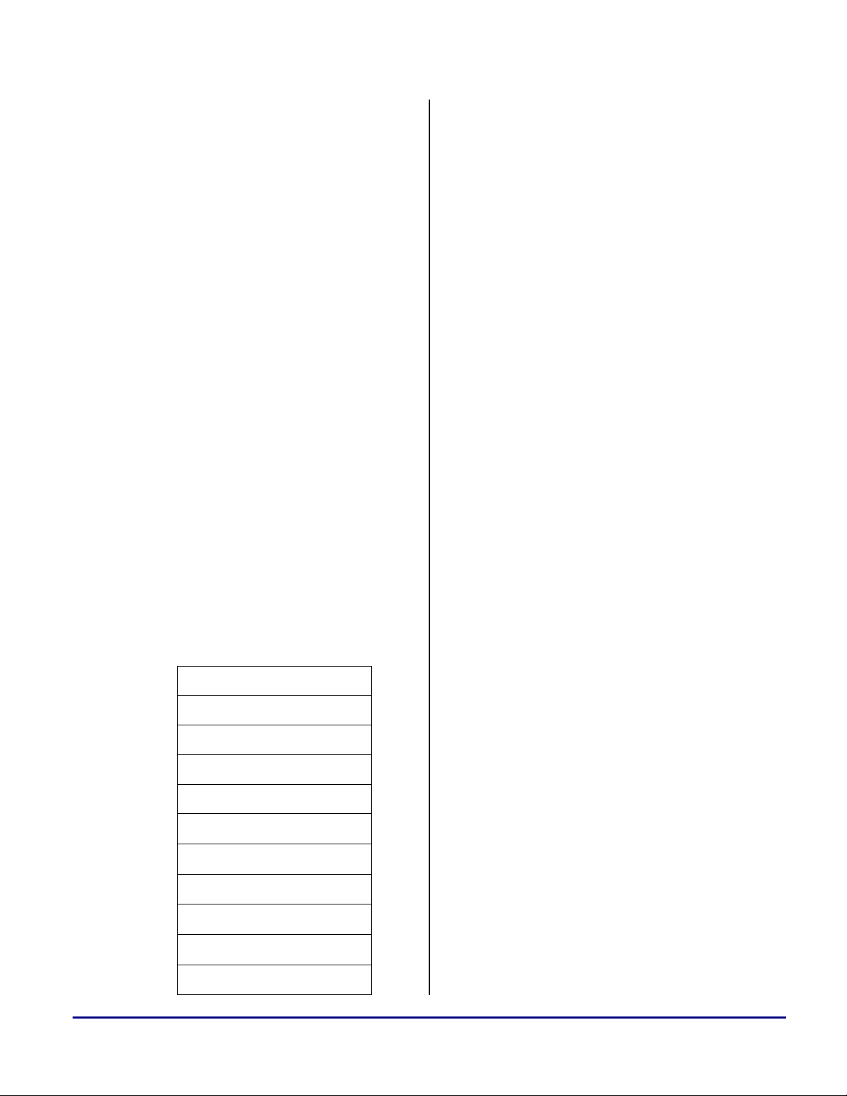
Listing 1. Example memory definition of
“dummy address”
MEMORY
{
Locating Overlay Information
The code that locates the overlay information is
memsdram { TYPE(PM RAM) START(0x00600000)
END(0x006FFFFF) WIDTH(48) }
}
implemented in the file Ovl_Init.asm. Its
objective is to run through the PROM to check
Copyright 2002, Analog Devices, Inc. All rights reserved. Analog Devices assumes no responsibility for customer product design or the use or application of
customers’ products or for any infringements of patents or rights of others which may result from Analog Devices assistance. All trademarks and logos are property
of their respective holders. Information furnished by Analog Devices Applications and Development Tools Engineers is believed to be accurate and reliable,
however no responsibility is assumed by Analog Devices regarding the technical accuracy and topicality of the content provided in all Analog Devices’ Engineer-toEngineer Notes.
Page 2
a
In the example shown in Listing 1 above, the
linker would generate an address in the range of
0x600000 to 0x6FFFFF for overlays defined in
the memsdram section.
Knowing that all of our overlays are placed in
this “dummy” location in the range of 0x600000
to 0x6FFFFF, we can check R3 each time after
we read the boot info for a value within this
range. When we find a section with a destination
address in this range, we then know that it
belongs to an overlay. This is done in the
check_routine portion of the Ovl_Init.asm file.
Whenever an overlay section is discovered, three
pieces of information are written into designated
buffers:
• the “real” live address that the overlay
resides in ROM,
• the section count size from R2, and
• the section data or code type from R0.
In addition to determining whether a section
belongs in an overlay, the check_routine code
also has to know how much to increment by to
read the next section’s information.
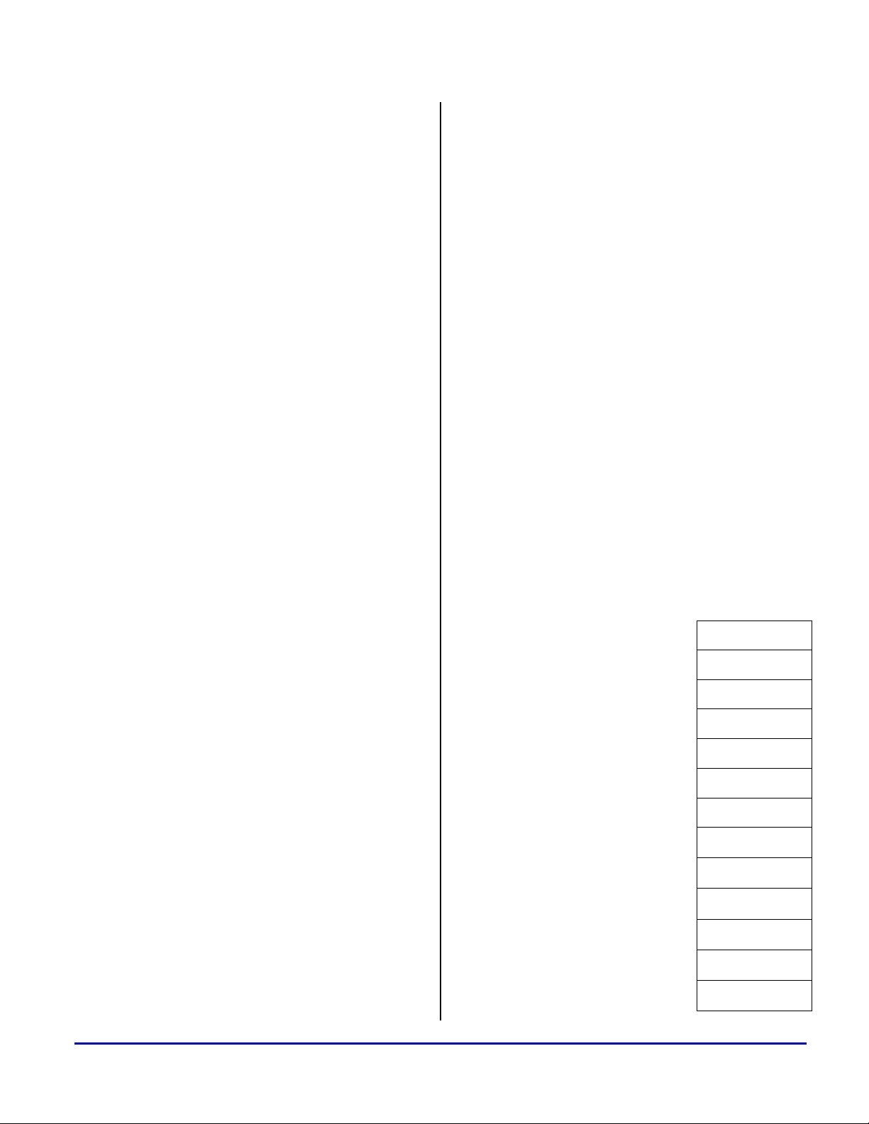
Figure 1. Illustration of info in PROM
0x4200E2E
0x4200E3A
0x4200E52
Tag = 0x15
Count = 0x4
Address = 0x60003C
...Code begins at 0x4200E3A…
Tag = 0x19
Count = 0x14
Figure 1 above shows an example illustration of
three sections’ info in the PROM. For this
example, after the first time the check_routine is
initiated, we will know 4 pieces of information:
• R0 = 0x15 (Section Type)
• R2 = 0xA (Section size)
• R3 = 0x60003C (Section live address)
• Current PROM address = 0x4200E2E
The current PROM address can be read from the
External Memory DMA Index register (EIEP0).
We see that the value in R3 corresponds to the
“dummy” live address that we’ve assigned to
overlays; therefore, we know that this particular
section belongs to an overlay. By checking the
type info in R0, we know that this section
contains code. Therefore, accounting for the
space that the tag, count, and address info takes
up in the PROM (0xC locations), we know that
code begins at 0x4200E3A (0x4200E2E + 0xC).
At this point, we record the type (R0) in the
total_sec_type buffer, size (R2) in the
total_sec_size buffer, and “real” live address
(0x4200E3A) into the total_live_addr buffer.
To read the next section’s info, the check_rout ine
increments the EIEP0 to 0x4200E52. It
calculates this address by using this formula:
(Addr. of code) + (size of code)(6)
Six 8-bit locations in the PROM make up one
internal 48-bit instruction. The size of the code
(read into R2) is the internal word size.
Therefore to find the section size in the PROM,
we multiply the internal word size by 6. Adding
this to the beginning address of the code, we get
the next section’s starting location in the PROM.
0x4200E5E
0x4200E6A
Using Code Overlays from ROM on the ADSP-21161N EZ-KIT Lite (EE-180) Page 2 of 9
Address = 0x600044
Tag = 0x15
Count = 0x8
Address = 0x60006C
...Code begins at 0x4200E6A…
Example 1. Locating the next section’s
address from a code type
Type = 0x15 (Code)
Code begins at 0x4200E3A
Internal size of code = 0xA
Page 3
a
(0x4200E3A) + (0x4)(6) = 0x4200E52
To accurately locate the address of the next
section’s info, the section type must be correctly
interpreted. For the example shown in Figure 1,
the section tag beginning at address 0x4200E52
is 0x19 and the count is 0x14. This tag indicates
a zero type, and the count indicates an internal
word size of 0x14. This is an equivalent of 0x78
8-bit locations in the PROM. However, for zero
types, the loader does not generate all the zeros
and fill up the PROM with zeros. This would be
a waste of valuable space. Instead, only the tag,
count, and live address are provided. Later in the
discussion of the overlay manager, we will
discuss how to handle the zero type sections. For
the purpose of the check_routine now, we only
need to know that for zero type sections, we find
the next section’s address by simply adding 0xC
to the current PROM address (to account for the
space that the tag, count, and address info takes
up in the PROM).
• account for the overlay id
information that’s embedded in the
loader file
To check how many sections are in each overlay,
we compare the individual section sizes to the
entire overlay size. In the check_routine of the
previous file, we placed all the section sizes into
the total_sec_size buffer. At run time, the linker
also generates constants with each overlay’s total
run size. Therefore, by comparing the individual
section size to the entire overlay size, we can find
out how many sections are in each overlay. This
information is stored in the num_ovl_sec buffer.
When the loader file is created, th e overlay id is
embedded after the tag, count, and address info.
For overlays with multiple sections, the overlay
id is embedded only once, after the overlay’s first
set of tag, count, and address info. Figure 2
illustrates this.
Example 2. Locating the next section’s
address from a zero type
Type = 0x19 (Zero)
Section info begins at 0x4200E52
(0x4200E52) + (0xC) = 0x4200E5E
The Ovl_Init.asm file checks every sections’ info
until it reaches a tag of 0x0, which indicates that
there are no more sections.
Parsing Overlay Information
Now that all the overlay sections’ information
have been collected, the Ovl_Sec_Info.asm file
parses it to determine:
• the number of section types in each
overlay
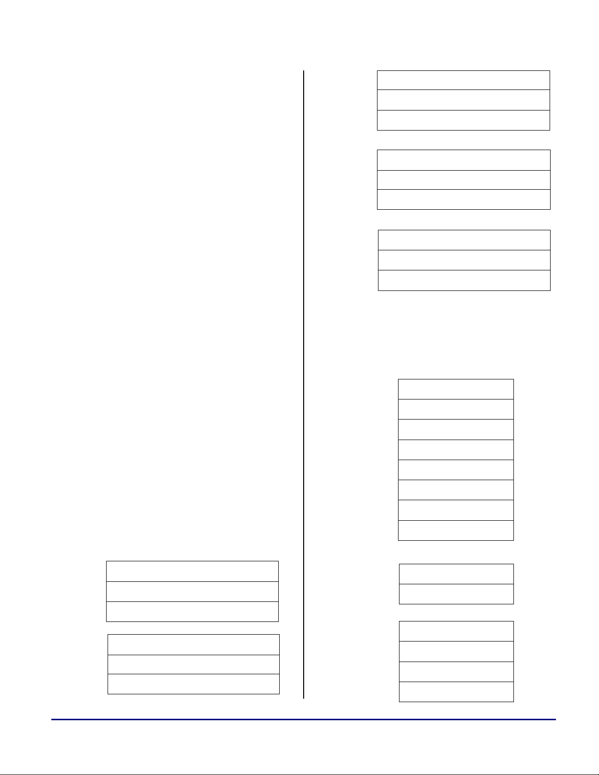
Figure 2. Illustration of overlay id
embedded in section info in PROM
Ovl 1, Sec. 1 0x4200DDA
0x4200DE6
0x4200DEC
Ovl. 1, Sec. 2 0x4200E22
0x4200E2E
Ovl. 2, Sec. 1
Tag
Count
Address
Overlay ID 1
….. Code …..
Tag
Count
Address
….. Code …..
Tag
Count
Address
Overlay ID 2
Using Code Overlays from ROM on the ADSP-21161N EZ-KIT Lite (EE-180) Page 3 of 9
Page 4

a
It is important to account for the embedded
overlay id information in order for the overlay
manager to DMA the proper code section into
internal memory.
The next two examples illustrate the correct
calculation of the code’s starting address in the
PROM.
If section is the first of a multiple section overlay
or a single section overlay, use the following
formula:
(Start addr. of section) + (0xC) + (0x6)
If section is part of a multiple section overlay, but
not the first section, then there will be no overlay
id embedded. The code’s starting address will
immediately follow the tag, count, live address
info. Calculate according to the formula:
(Start addr. of section) + (0xC)
Example 3. Locating the code’s starting
address with embedded overlay id
Using Figure 2, Overlay 1, Section 1:
Start addr. of section info = 0x4200DDA
Locations for tag, count, address = 0xC
Locations in PROM for overlay id = 0x6
(0x4200DDA)+(0xC)+(0x6)=0x4200DEC
Example 4. Locating the code’s starting
address without embedded overlay id
Using Figure 2, Overlay 1, Section 2:
Start addr. of section info = 0x4200E22
Locations for tag, count, address = 0xC
(0x4200DDA) + (0xC) = 0x4200E2E
The corrected section code start addresses are
then written into the total_live_addr buffer.
Overlay Manager
The overlay manager handles the process of
DMAing the code sections into internal memory,
zero filling instruction memory for zero type
sections, and executing the overlay.
When an overlay is called, the overlay id and the
run starting address are stored in registers R0 and
R1, respectively. The overlay manager first
checks whether the overlay called has been
previously DMAed into internal memory already.
If so, there is no need to DMA the overlay again.
The program simply jumps to the run starting
address of the overlay and executes. If the
overlay is not in internal memory yet, the process
of setting up the DMA starts.
In order to setup the DMA properly, we need to
perform the following:
1) Check whether the overlay to be DMAed
is overlay 1.
2) Check how many sections are in the
overlay to be DMAed.
3) Check section type to determine what
DMA parameters are needed.
Check for Overlay 1
The section information for overlay 1 is always
located at the beginning of the information
buffers. For example, the first entry in the
total_live_addr buffer would contain the live
address of the first section in overlay 1. If the
overlay to be DMAed is overlay 1, then we know
that the modifier to our information buffers is 0
because the information to overlay 1 starts at the
beginning of the buffer. However, if we checked
that the overlay to be DMAed is not overlay 1,
we need to calculate the modifier value in order
to access the start of the information for the
overlay we are DMAing.
Using Code Overlays from ROM on the ADSP-21161N EZ-KIT Lite (EE-180) Page 4 of 9
Page 5

a
Figure 3 illustrates the stored live addresses of
four overlays with multiple and single section in
memory. Listing 2 provides the actual code to
determine the modifier value for locating the
starting information of overlay 3.
Figure 3. Illustration of overlay section
information in data buffer
total_live_addr buffer
0x5030D
0x5030E
0x5030F
0x50310
0x50311
0x50312
0x50313
0x50314
0x50315
Listing 2. Code implementation for
determining modifier value to locate
starting information for overlay 3
/* Summation loop to determine total
number of sections prior to overlay 3.
Store sum in register R8. */
I9 = total_live_addr; // I9 = 0x5030D
M11 = R8; // M11 = 6
modify(I9, M11); // I9 = 0x50313
In the Ovl_Sec_Info.asm file, we’ve determined
the number of sections in each overlay. To locate
where the information for overlay 3 starts, we
Ovl 1, Sec 1, Live Addr. in PROM
Ovl 1, Sec 2, Live Addr. in PROM
Ovl 1, Sec 3, Live Addr. in PROM
Ovl 1, Sec 4, Live Addr. in PROM
Ovl 1, Sec 5, Live Addr. in PROM
Ovl 2, Sec 1, Live Addr. in PROM
Ovl 3, Sec 1, Live Addr. in PROM
Ovl 4, Sec 1, Live Addr. in PROM
Ovl 5, Sec 1, Live Addr. in PROM
implement a summation loop to determine how
many total sections there are in the overlays prior
to overlay 3. Then, we place that result in an
arbitrary register, R8. We have an index register,
I9, pointing to the beginning of the
total_live_addr buffer. After we determine the
number of sections there are prior to overlay 3,
we place that value in modifier M11. Then,
update the index register I9 with the modify
value. We now have I9 pointing to the
information location for overlay 3.
In the case where we are DMAing overlay 1, we
do not need to calculate the modify value because
we know that its information is located at the
beginning of the buffer.
Check Number of Sections
The next objective is to check the number of
sections in the overlay to be DMAed. In order to
setup the DMA properly, we need to know the:
• live address of the code (location in
PROM to DMA from),
• run address of code (location in
internal memory to DMA to),
• number of internal words to transfer
(size that code will take up in internal
memory), and
• number of external words to transfer
(size of code in PROM to read from).
Listing 3. Plit as defined in the ldf file
PLIT
{
R0 = PLIT_SYMBOL_OVERLAYID;
R1 = PLIT_SYMBOL_ADDRESS;
JUMP _OverlayManager;
}
For single section overlays, these parameters are
simple to determine. The run address is provided
Using Code Overlays from ROM on the ADSP-21161N EZ-KIT Lite (EE-180) Page 5 of 9
Page 6
a
when the overlay is first called. For this
application, it is stored in R1. See Listing 3. For
more information on plit tables and how overlays
work in general, see EE-66. By calculating the
modifier value (as shown in the previous section
above), the live address and number of internal
words can be determined from the
total_live_addr and total_sec_size buffers,
respectively. For the example shown in Figure 3,
the single section overlays are overlay 2, 3, 4,
and 5. Therefore, after calculating the respective
modifier values for each overlay, we know that
the live addresses for overlay 2, 3, 4, and 5 are
0x50312, 0x50313, 0x50314, and 0x50315,
respectively. After the internal word size is
determined from the total_sec_size buffer, the
external size is just 6x the internal size (six 8-bit
external words = one 48-bit internal word).
For multiple section overlays, the DMA
parameters are more difficult to determine. The
reason is because each section needs to be
DMAed separately, and the run address of where
the last section ended must be kept track of
constantly. Also, the code has to check whether
the section is a zero type. If so, no DMA is
performed. Instead, a zero loop will fill
instruction memory with zeros for the count size
of the section.
Figures 4 and 5 illustrate how the overlay maps
from external PROM memory space to internal
instruction memory space.
0x4021E
0x4021F
0x40221
06 BE 00 04 02 3A
………………….
………………….
End of section 3, overlay 1
End of section 3, overlay 1
0x40222
0x40223
0x40235
0x40236
0x40237
0x40238
nops begin, section 4, overlay 1
00 00 00 00 00 00
nops end, section 4, overlay 1
06 BE 00 04 02 3A
………………….
End of section 5, overlay 1
Figure 5. Illustration of overlay live
space
0x4200DEC
0x4200DED
0x4200DEE
0x4200DEF
0x4200DF0
0x4200DF1
………….
00
00
00
00
71
0F
………………….
Figure 4. Illustration of overlay run space
0x40201
0x40202
0x40209
0x4020A
0x4020B
0x4021D
Using Code Overlays from ROM on the ADSP-21161N EZ-KIT Lite (EE-180) Page 6 of 9
0F 71 00 00 00 00
…………………
End of section 1, overlay 1
nops begin, section 2, overlay 1
00 00 00 00 00 00
nops end, section 2, overlay 1
0x4200E21
0x4200E22
0x4200E2D
0x4200E3A
0x4200E3B
0x4200E3C
0x4200E3D
End of section 1
Section 2: Tag,
Count, Address Info
3A
02
04
00
Page 7

b
a
0x4200E3E
0x4200E3F
…………..
0x4200E51
0x4200E52
0x4200E5D
0x4200E6A
0x4200E6B
0x4200E6C
0x4200E6D
0x4200E6E
0x4200E6F
…………..
0x4200E99
Now, let’s examine the procedure to bring a
multiple section overlay, such as the one shown
in Figures 4 and 5, into internal memory.
BE
06
…………………..
End of section 3
Section 4: Tag,
Count, Address Info
3A
02
04
00
BE
06
………………….
End of section 5
Listing 4. Code implementation of DMA
routine for code sections
/* Initially disable and clear out DMA
channel 10 */
R12 = 0;
DM(DMAC10) = R12;
/* Write Live Address to EPB0 external index
address register – previously read into R7 */
DM(EIEP0) = R7;
/* Setup EPB0 external and internal index
modify registers to 1 */
R12 = 1;
DM(EMEP0) = R12;
DM(IMEP0) = R12;
/* Save old value of SYSCON */
R13 = DM(SYSCON);
R12 = BSET R13 BY 1;
DM(SYSCON)=R12;
/* Write Run Address to EPB0 internal index
address register – previously read into R5*/
By checking the section type info in the
total_sec_type buffer, we know that section 1 of
overlay 1 contains code. Therefore, we need to
determine the live address of the code, run
address, internal word size, and external word
size. We know the live address by checking the
total_live_addr buffer. Because this is the first
section of the overlay, we know the run address
is the run starting address for overlay 1. This is
stored in R1, as shown in Listing 3. We know
the internal word size by checking the
total_sec_size buffer. And finally, we know that
for code, the external word size is 6x the internal
word size (six 8-bit external words = one 48-bit
internal word). The first section is now ready to
be DMAed into internal memory. Listing 4
shows the code sequence for the DMA process.
Using Code Overlays from ROM on the ADSP-21161N EZ-KIT Lite (EE-180) Page 7 of 9
DM(IIEP0) = R5;
/* Set number of "Run" internal words to
transfer – previously read into R9*/
DM(CEP0) = R9;
/* Set number of "Live" external words to
transfer. Multiply “Run” internal words by 6
because (six 8-bit external words = one 48internal word). */
R9 = R9 * R15(uui);
DM(ECEP0) = R9;
R12=0x421;
DM(DMAC10) = R12; //Enable DMA
IDLE;
DM(SYSCON)=R13; //Restore SYSCON
it
Page 8

a
After the first section has been DMAed into
internal memory, we begin to bring section two
into internal memory. By checking the next
entry in the total_sec_type buffer for the next
section’s type info, we realize that the section is a
zero type. For zero type sections, no DMA is
required. The only pieces of information needed
are the run address and number of internal words
to transfer. By reading the next entry in the
total_sec_size buffer, we know the number of
internal words to transfer. To find the run
address, we implement a get_index routine in this
application that keeps track of the run address
where the last section ended. As Figure 4 above
shows, the first section ends at address 0x40209,
and the second section begins at address
0x4020A. Listing 5 shows the code sequence for
zero filling internal memory.
Listing 5. Code implementation of zero fill
loop for zero type sections
/* R5 contains the run address for the next
section. Load run address to I5 pointer */
I5 = R5;
/* PX contains 0x0 to zero fill memory */
PX=0x0;
/* R9 contains the number of times to loop
(this section’s internal size). M5 contains
0x1 – increment one after each write. */
lcntr = R9, do zero_loop until lce;
zero_loop: DM(I5, M5)=PX;
Depending on whether the section is a code or
zero type, the application continues the DMA or
zero fill implementation in Listings 4 and 5 until
it detects that all the sections in this overlay have
been brought into internal memory.
At that point, it jumps to the run starting address
of the overlay (stored in R1 – see Listing 3) and
begins execution of the code.
Using Code Overlays from ROM on the ADSP-21161N EZ-KIT Lite (EE-180) Page 8 of 9
Page 9
References
EE-66 Using Memory Overlays
EE-151 Implementing Software Data Overlays
for the ADSP-21161 Using the EZ-KIT
Linker and Utilities Manual for ADSP-21xxx
Family DSP’s
ADSP-21161 SHARC DSP Hardware Reference
Manual
Document History
Version Description
December 5, 2002 by C.Lam Initial Release
a
Using Code Overlays from ROM on the ADSP-21161N EZ-KIT Lite (EE-180) Page 9 of 9
 Loading...