

Page 1
Engineer To Engineer Note EE-171
s
a
Technical Notes on using Analog Devices' DSP components and development tools
Contact our technical support by phone: (800) ANALOG-D or e-mail: dsp.support@analog.com
Or vi sit ou r on-l ine re sourc es ht tp:// www.analog.com/dsp and http://www.analog.com/dsp/EZAnswer
ADSP-BF535 Blackfin® Processor Multi-cycle Instructions and Latencies
Contributed by DSP Apps May 13, 2003
Introduction
This document describes the multi-cycle instructions and latencies specific to the ADSP-BF535
Blackfin® Processor. Multi-cycle instructions are ones that take more than one cycle to complete. This
cycle penalty cannot be avoided without removing the instruction that caused it. A latency condition can
occur when two instructions require extra cycles to complete because they are close to each other in the
assembly program. The programmer can avoid this cycle penalty by separating the two instructions.
Other causes for latencies are memory stalls and store buffer hazards. For many latency conditions, a
discussion of how to improve performance is also provided.
Multicycle Instructions
This section describes the instructions that take more than one cycle to complete. All instructions not
mentioned in this discussion are single-cycle instructions.
Multi-cycle instructions consist these types: Push Multiple/Pop Multiple, 32-bit Multiply, Call, Jump,
Conditional Branch, Return, Core and System Synchronization, Linkage, and Interrupts and Emulation.
In the following examples, the total number of cycles needed to complete a certain instruction is shown
next to the corresponding instruction.
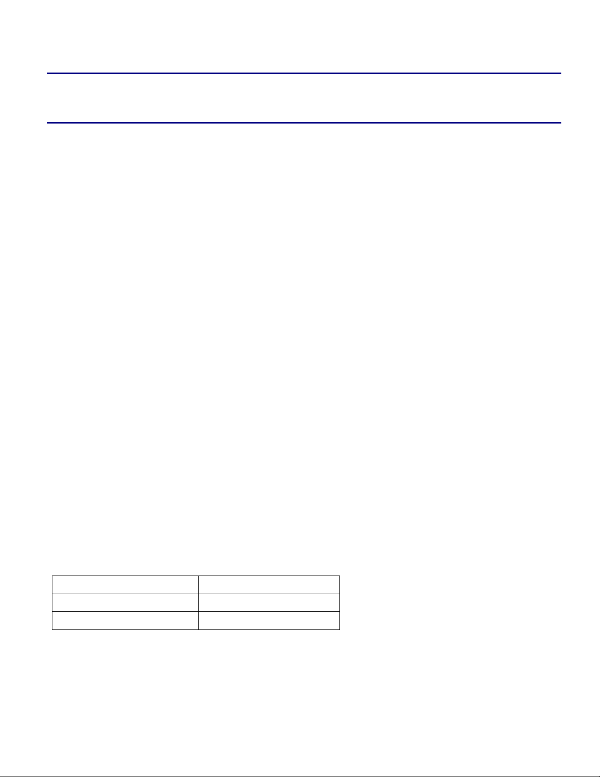
Push Multiple/Pop Multiple
The Push Multiple and Pop Multiple instructions take n cycles to complete, where n is the number of
registers pushed or popped.
Example Number of Cycles
[--SP] = (R7:0, P5:0); 14
(R7:0, P5:3) = [SP++]; 11
Copyright 2003, Analog Devices, Inc. All rights reserved. Analog Devices assumes no responsibility for customer product design or the use or application of
customers’ products or for any infringements of patents or rights of others which may result from Analog Devices assistance. All trademarks and logos are property
of their respective holders. Information furnished by Analog Devices Applications and Development Tools Engineers is believed to be accurate and reliable, however
no responsibility is assumed by Analog Devices regarding technical accuracy and topicality of the content provided in Analog Devices’ Engineer-to-Engineer Notes.
Page 2
a
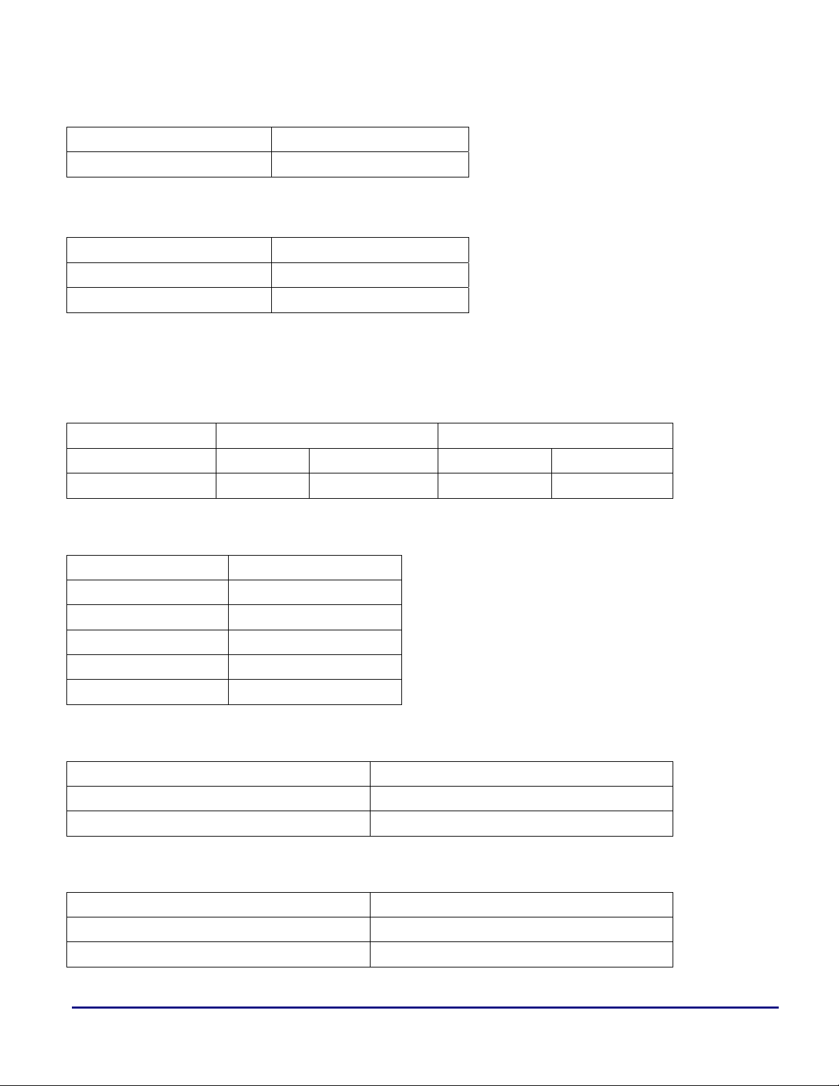
32-bit Multiply (modulo 2
Example Number of Cycles
R0 *= R1; 5
32
)
Call, Jump
Example Number of Cycles
CALL 0x22; 4
JUMP(P0); 4
Conditional Branch
The number of cycles a branch takes depends on the prediction as well as the actual outcome.
Prediction Taken Not taken
Outcome
Number of Cycles
Taken Not taken Taken Not taken
4 cycles 7 cycles 7 cycles 1 cycle
Return
Examples Number of Cycles
RTX; 7
RTE; 7
RTN; 7
RTI; 7
RTS; 4
Core and System Synchronization
Examples Number of Cycles
CSYNC; 7
SSYNC; 7
Linkage
Examples Number of Cycles
LINK 4; 4 cycles
UNLINK; 3 cycles
ADSP-BF535 Blackfin® Processor Multi-cycle Instructions and Latencies (EE-171) Page 2 of 15
Page 3

a
Interrupts and Emulation
Examples Number of Cycles
RAISE 10; 3 cycles
EMUEXCPT; 3 cycles
STI R4; 3 cycles
Instruction Latencies
Unlike multi-cycle instructions, instruction latencies (or stall cycles) are contingent on the placement of
specific instruction pairs relative to one another. They can be avoided by separating them by as many
instructions as there are stalls incurred between them. For example, if a pair of instructions incurs a 2
cycle latency, separating them by two instructions will eliminate that latency.
Bold blue type is used to identify register dependencies within the instruction pairs. An example of a
dependency is when a register is accessed in the instruction immediately following an instruction that
modified the register. The lack of the color blue in a entry indicates that the latency condition will occur
regardless of what registers are used. Italicized red type is used to highlight the stall consequences.
Instruction latencies are separated into these groups: Accumulator to Data Register Latencies, Register
Move Latencies, Move Conditional and Move CC Latencies, Loop Setup Latencies, Instructions Within
Hardware Loop Latencies, Loop Buffer Misalignment Latencies, and Miscellaneous Latencies. The total
cycle time of each entry can be calculated by adding the cycles taken by each instruction to the number of
stall cycles for the instruction pair.
Refer to the Appendix for abbreviations, instruction group descriptions, as well as register groupings.
ADSP-BF535 Blackfin® Processor Multi-cycle Instructions and Latencies (EE-171) Page 3 of 15
Page 4

Accumulator to Data Register Latencies
Description Example <Cycles + Stalls>
a
- dreg = Areg2Dreg op
- video op using dreg as src
- dreg = Areg2Dreg Op
- rnd12/rnd20 using dreg as src
- dreg = Areg2Dreg Op
- shift/rotate op using dreg as src
- dreg = Areg2Dreg Op
- add on sign using dreg as src
R1 = R6.L * R4.H (IS);
R5 = BYTEOP1P (R3:2, R1:0);
R4.L = (A0 = R3.H*R1.H);
R0.H = R2 + R4 (RND12);
R4.L = (A0 = R3.H*R1.H);
R1 = ROT R2 BY R4.L;
R0.H=R0.L=SIGN(R2.H)*R3.H+SIG
N (R2.L)*R3.L;
R6.H=R6.L=SIGN(R0.H)*R1.H+SIGN
(R0.L)*R1.L;
<1>
<1+2>
<1>
<1+1>
<1>
<1+1>
<1>
<1+1>
Register Move Latencies
In each of the following cases, the stall condition occurs when the same register is used in both
instructions.
Description Example <Cycles + Stalls>
- dreg = sysreg
- ALU op using dreg as src (or vector
ALU op)
- dreg = preg
- sysreg = dreg
- dreg = sysreg
- dreg = dreg
- dreg = sysreg
- multiply/video op with dreg as src
- dreg = sysreg
- accreg = dreg
- preg = dreg
- any op using preg
- dagreg = dreg
- any op using dagreg
R0 = LC0;
R2 = R1 + R0;
------------------------------------------
R2 = LC0;
R1.L = R2 (RND);
R0 = P0;
ASTAT = R0;
R0 = ASTAT;
R1 = R0;
R0 = LC0;
R2.H = R1.L * R0.H;
R0 = LC0;
A0 = R0;
P0 = R3;
R0 = P0;
I3 = R3;
R0 = I3;
<1>
<1+1>
-----------------------------------------<1>
<1+1>
<1>
<1+1>
<1>
<1+1>
<1>
<1+2>
<1>
<1+1>
<1>
<I+3>
<1>
<1+3>
ADSP-BF535 Blackfin® Processor Multi-cycle Instructions and Latencies (EE-171) Page 4 of 15
Page 5

a
- dreg = sysreg
- sysreg = dreg
- accreg = sysreg
- accreg = dreg
- accreg = sysreg
- accreg = preg
- accreg = sysreg
- accreg = accreg
- accreg = sysreg
- dreg = accreg
- accreg = sysreg
- sysreg = accreg
- accreg = sysreg
- math op using accreg as src
- accreg = sysreg
- POP to accreg
- POP to dagreg
R0 = LC0;
ASTAT = R0;
A0.w = LC0;
A0 = R0;
A0.w = LC0;
A0.w = P0;
A0.w = LC0;
A1 = A0;
A0.w = LC0;
R0.L = A0.x;
A0.w = LC0;
ASTAT = A0.w;
A1.x = LC0;
R1.H = (A0+=A1);
A0.w = LC0;
A0.w = [SP ++ ];
I3 = [SP++];
<1>
<1+1>
<1>
<1+1>
<1>
<1+1>
<1>
<1+1>
<1>
<1+1>
<1>
<1+1>
<1>
<1+1>
<1>
<1+1>
<1>
- any op using dagreg
R0 = I3;
<1+3>
Move Conditional and Move CC Latencies
In each of the following cases, the stall condition occurs when the same register is used in both
instructions.
Description Example <Cycles + Stalls>
- dreg = CC
- if CC dreg = dreg
- if CC dreg = dreg
- multiply/video op using dreg as src
- if CC dreg = preg
- math op using dreg as src
R0 = CC;
if CC R1 = R0;
if CC R0 = R1;
R2.H = R1.L * R0.H;
-----------------------------------------if CC R1 = R3;
SAA (R3:2, R1:0);
if CC R0 = P0;
R2 = R1 + R0;
<1>
<1+1>
<1>
<1+1>
-----------------------------------------<1>
<1+1>
<1>
<1+1>
------------------------------------------
if CC R3 = P1;
ADSP-BF535 Blackfin® Processor Multi-cycle Instructions and Latencies (EE-171) Page 5 of 15
-----------------------------------------<1>
Page 6

a
<1+1>
<1>
<1+2>
-----------------------------------------<1>
<1+2>
<1>
<1+2>
<1>
<1+3>
<1>
<1+1>
- dreg = CC
- math op using dreg as src
- dreg = CC
- CC = dreg
- if CC preg = dpreg
- any op using preg
- if CC dreg = dpreg
- CC = dreg
SAA (R3:2, R1:0);
R0 = CC;
R2.H = R1.L * R0.H;
------------------------------------------
R1 = CC;
SAA (R3:2, R1:0);
R0 = CC;
CC = R0;
if CC P0 = R1;
R4 = P0;
if CC R0 = R1;
CC = R0;
Loop Setup Latencies
There following are latencies specific to the configuration of the zero-overhead looping mechanism.
Description Example <Cycles + Stalls>
- loop setup
- loop setup with same LC
- modification of LT or LB
- loop setup with same loop registers
- loop setup and LC0/LC1 != 0
- any op
- LC0/LC1 reg written to
- any op
- LT0/LB0 written to and LC0 != 0
- any op
- LT1/LB1 written to and LC1 != 0
- any op
- kill while loop buffer is being written
due to: interrupt, exception, NMI,
emulation events
LSETUP (top1, bottom1) LC0 = P0;
LSETUP (top2, bottom2) LC0 = P1;
LT0 = [SP++];
LSETUP (top, bottom) LC0 = P0;
LSETUP (top, bottom) LC0 = P0;
NOP;
LC0 = R0;
NOP;
LT0 = [SP++];
NOP;
LB1 = P0;
NOP;
<3>
<1>
<1+1>
<1>
<1+3>
<1>
<1+1>
<1>
<1+4>
<1>
<1+4>
<1>
<1+4>
ADSP-BF535 Blackfin® Processor Multi-cycle Instructions and Latencies (EE-171) Page 6 of 15
Page 7

a
Instructions Within Hardware Loop Latencies
The following stall conditions occur when the listed instruction is present within a hardware loop.
Instruction Number of Stalls in the Next
Iteration of the Loop
move conditional or POP into any of LC/LB/LT registers <3>
loop setup in the first 3 instructions of the loop <3>
branch in the first 3 instructions of the loop (JUMP, CALL, conditional branch) <3>
interrupt or exception in the first 4 instructions of the loop <3>
CSYNC or SSYNC <3>
inner hardware loop’s bottom is within the outer hardware loop’s first four instructions <3>
RTS, RTN, RTE, RTX, RTI <3>
Loop Buffer Misalignment
The ADSP-BF535 Blackfin Processor has two loop buffers that correspond to the two zero-overhead loop
units. These buffers guarantee that there are no pipeline kills due to the implicit conditional jump at the
end of each loop iteration. Each loop buffer has four 64-bit locations and can store up to four instructions.
These four instructions are the first four instructions starting at the beginning of a hardware loop.
While the loop buffer mechanism is transparent to the software user, there are cases where code will incur
stalls due to improper instruction data alignment relative to the loop buffer.
There are two possible scenarios to consider:
The loop contains four instructions of less.
All four (or less) instructions will fit in the loop buffer. There is nothing a programmer must do in this
case to ensure that there are no stalls due to loop buffer misalignment.
The loop buffer contains five or more instructions.
Four instructions will fit into the loop buffer. In order to eliminate a stall latency, the fifth instruction
must be fully contained in the next 64-bit instruction fetch. For example, if the fifth instruction in a
loop is a 64-bit instruction, and this instruction is not aligned to a 64-bit boundary, then it will take two
64-bit fetches to grab the instruction from L1 memory. Therefore, a one-cycle stall is incurred in each
iteration of the loop.
Miscellaneous Latencies
The following latencies do not fall into any of the above categories.
ADSP-BF535 Blackfin® Processor Multi-cycle Instructions and Latencies (EE-171) Page 7 of 15
Page 8

Description Example <Cycles + Stalls>
a
- move register or POP to I0 or I1
- SAA,BYTEOP2P,BYTEOP3P
- move register or POP to I0 or I1
- BYTEOP1P/16P/16M, BYTEUNPACK
- write to return register
- return op
- math op
- multiply/video op with RAW data
dependency
- dreg = search
- math op using dreg
I1 = [SP++];
R0 = BYTEOP3P (R1:0, R1:0)
(HI);
I0 = R0;
R3 = BYTEOP1P (R3:2, R1:0);
RETI = P0;
RTI;
-----------------------------------------RETS = P3;
RTS;
R2 = R3 + R1;
R4.H = R2.L * R0.H;
------------------------------------------
R3 *= R4;
SAA (R3:2, R1:0);
(R3, R0) = search R1 (LE);
R2.H = R1.L * R0.H;
<1>
<1+5>
<1>
<1+5>
<1>
<1+4>
-----------------------------------------<1>
<1+4>
<1>
<1+1>
-----------------------------------------<1>
<1+1>
<1>
<1+2>
- LOAD/POP to preg
- any op using preg
- POP to dagreg
- any op using dagreg
- core and system MMR access R0 = [P0]; // P0 = MMR address <1+2>
- LC0/LB0 = dreg
- I0 modulo update (similarly for the
corresponding LC1/LB0 and I1 registers)
P0 = [FP+-4];
R0 = P0;
I3 = [SP++];
R0 = I3;
LC0 = R0;
R1 = [I0++];
------------------------------------------
LB1 = R2;
I1 += 4;
------------------------------------------
LC1 = R3;
R4 = [I1++M2];
------------------------------------------
LC0 = R5;
I0 += M2;
<1>
<1+3>
<1>
<1+3>
<1>
<1+3>
-----------------------------------------<1>
<1+3>
-----------------------------------------<1>
<1+3>
-----------------------------------------<1>
<1+3>
ADSP-BF535 Blackfin® Processor Multi-cycle Instructions and Latencies (EE-171) Page 8 of 15
Page 9

a
L1 Data Memory Stalls
L1 data memory (DM) stalls can be incurred by accessing L1 data memory. Accesses can either be
explicit (if the data memory is configured as SRAM) or implicit (if the data memory is configured as
cache). Some of these stalls are multi-cycle instruction conditions, and some are latency conditions. The
specifics are described in each entry.
Bold blue type is used to highlight the causal factors in offending instructions. Italicized red type is used
to highlight the stall consequences.
Sub-bank Access Collision
SRAM Access (1 cycle stall)
This stall can only occur when an instruction accesses memory configured as SRAM. The ADSP-BF535
Blackfin Processor has two data memory super-banks. Within each super-bank, there exist four
contiguous 4096 byte (4KB) sub-banks. The following table shows the memory ranges for each of the
sub-banks.
Data Memory Mini-Bank Address Range
super-bank A, sub-bank 0 0xFF80 0000 - 0xFF80 0FFF
super-bank A, sub-bank 1 0xFF80 1000 - 0xFF80 1FFF
super-bank A, sub-bank 2 0xFF80 2000 - 0xFF80 2FFF
super-bank A, sub-bank 3 0xFF80 3000 - 0xFF80 3FFF
super-bank B, sub-bank 0 0xFF90 0000 - 0xFF90 0FFF
super-bank B, sub bank 1 0xFF90 1000 - 0xFF90 1FFF
super-bank B, sub-bank 2 0xFF90 2000 - 0xFF90 2FFF
super-bank B, sub-bank 3 0xFF90 3000 - 0xFF90 3FFF
If there are two simultaneous accesses in a multi-issue instruction to the same sub-bank, a one cycle stall
is incurred.
Example <Cycles + Stalls>
(I0 is address 0xFF80 1348, I1 is address 0xFF80 1994)
R1 = R4.L * R5.H (IS) || R2 = [I0++] || [I1++] = R3;
<1+1>
(stall is due to a collision in the sub-bank 1 of b ank A)
ADSP-BF535 Blackfin® Processor Multi-cycle Instructions and Latencies (EE-171) Page 9 of 15
Page 10

a
A collision occurs regardless if the accesses are both loads, or load and store. In the case where the first
access is a load (DAG0) and the second is a store (DAG1), the cycles incurred are seen by the store buffer
(see ‘Store Buffer Overflow’ below).
Cache Access (1 cycle stall)
This stall can only occur when one or both L1 data banks are configured as cache.
One Bank is Configured as Cache
When only one bank is configured as cache, data memory accesses will always be cached to the same
super-bank. Therefore, it is necessary only to determine the cache sub-bank.
The ADSP-BF535 Blackfin Processor has four 4 KB sub-banks within each cache super-bank. Bits 13
and 12 of the data address determine which sub-bank data will be cached into. In the following example,
super-bank A is configured as cache.
Data Address[13:12] Sub-bank Selected (Super-bank A is Cache)
00 sub-bank 0 (0xFF80 0000 - 0xFF80 1000)
01 sub-bank 1 (0xFF80 1000 - 0xFF80 2000)
10 sub-bank 2 (0xFF80 2000 - 0xFF80 3000)
11 sub-bank 3 (0xFF80 3000 - 0xFF80 4000)
If the addresses in a dual memory access (multi-issue) instruction cache to the same sub-bank, a 1 cycle
stall will be incurred.
Example <Cycles + Stalls>
(I0 is address 0xFF80 2348, I1 is address 0xFF80 2994)
R1 = R4.L * R5.H (IS) || R2 = [I0++] || [I1++] = R3;
<1+1>
(stall is due to a collision in mini-bank 2)
A collision occurs regardless if the accesses are both loads, or load and store. In the case where the first
access is a load (DAG0) and the second is a store (DAG1), the cycles incurred are seen by the store buffer
(see ‘Store Buffer Overflow’ below).
The cache collision rule is: If a multi-issue instruction accesses data from Addr1 and Addr2 and
(Addr1[13:12] == Addr2[13:12]), then a collision will occur.
ADSP-BF535 Blackfin® Processor Multi-cycle Instructions and Latencies (EE-171) Page 10 of 15
Page 11

a
Both banks are configured as cache
If both banks are cacheable, one must also determine which super-bank the accesses are cached to (in
addition to sub-bank) to determine if there is a stall. This depends on the value of the DCBS bit of the
DMEM_CONTROL MMR. If DCBS is 1, address bit 23 is used as bank select. If DCBS is 0, address bit
14 is used as bank select. The following table and example assumes DCBS is 0:
Addr[14:12] Sub-bank Selected
000 bank A, sub-bank 0 (0xFF80 0000 - 0xFF80 1000)
001 bank A, sub-bank 1 (0xFF80 1000 - 0xFF80 2000)
010 bank A, sub-bank 2 (0xFF80 2000 - 0xFF80 3000)
011 bank A, sub-bank 3 (0xFF80 3000 - 0xFF80 4000)
100 bank B, sub-bank 0 (0xFF90 0000 - 0xFF90 1000)
101 bank B, sub-bank 1 (0xFF90 1000 - 0xFF90 2000)
110 bank B, sub-bank 2 (0xFF90 2000 - 0xFF90 3000)
111 bank B, sub-bank 3 (0xFF90 3000 - 0xFF90 4000)
If the addresses in a dual memory access (multi-issue) instruction cache to the same super-bank and
minibank, a 1 cycle stall will be incurred.
Example <Cycles + Stalls>
(I0 is address 0xFF80 2348, I1 is address 0xFF80 2994)
R1 = R4.L * R5.H (IS) || R2 = [I0++] || [I1++] = R3;
<1+1>
(stall is due to a collision in mini-bank 2)
A collision occurs regardless if the accesses are both loads, or load and store. In the case where the first
access is a load (DAG0) and the second is a store (DAG1), the cycles incurred are seen by the store buffer
(see ‘Store Buffer Overflow’ below).
The cache collision rule is:
When DCBS is 0:
If a multi-issue instruction accesses data from Addr1 and Addr2 and (Addr1[14:12] == Addr2[14:12]),
then a collision will occur.
When DCBS is 1:
ADSP-BF535 Blackfin® Processor Multi-cycle Instructions and Latencies (EE-171) Page 11 of 15
Page 12

a
If a multi-issue instruction accesses data from Addr1 and Addr2 and (Addr1[23,13:12] ==
Addr2[23,13:12]), then a collision will occur.
MMR Access
A read from any MMR space (core MMR or system MMR) results in a 2 cycle stall. This is because the
processor must wait for acknowledgement from the peripherals mapped to the MMRs being accessed.
Example <Cycles + Stalls>
(I0 contains an address between 0xFFC0 0000 and 0xFFFF
FFFF)
R2 = [I0++];
<1+2>
System Sub-bank Access Collision (this may have implications for the DMA engine)
A system access occurs when some external device, such as another processor in a multiple core system,
accesses L1 memory. Whenever the system accesses a sub-bank that is currently being accessed by the
core, a 1 cycle stall is incurred, because system memory accesses have higher priority than core accesses.
Store Buffer Overflow
The store buffer is a 5 entry FIFO which manages ADSP-BF535 Blackfin Processor instruction stores to
L1 and L2 memory. All instruction stores must go through the store buffer. Thus, if the buffer is full, the
ADSP-BF535 Blackfin Processor stalls until the FIFO moves forward and a space is freed.
The earliest time a store can leave the buffer is 4 instructions (not cycles necessarily) after it was entered.
This means that, under ideal circumstances, a continuous series of stores will take up 4 out of the 5 slots in
the store buffer. If only one of the stores is delayed by an extra cycle, there is no penalty as the store
buffer has 5 slots. There are many scenarios where the store buffer can become full. In order to account
for them, the programmer must keep track of the proximity of stores and how many cycles they each take.
If a multi-cycle store is required, the programmer must be sure that it isn’t followed too closely by other
stores as they may become backed up.
The following is a list of multi-cycle stores:
1. Stores to non-cacheable memory, e.g. MMR space
2. Stores to L2 memory
ADSP-BF535 Blackfin® Processor Multi-cycle Instructions and Latencies (EE-171) Page 12 of 15
Page 13

a
3. Mini-bank conflict where the store is from DAG1, i.e. the second access in a load/store multi-issue
instruction.
Example Number of Cycles
(I0 contains an address between 0xFFC0 0000 and 0xFFFF
FFFF)
[I0++] = R2;
<N>
Store Buffer Load Collision
This section describes cases where a load access collides with a pending store access in the store buffer.
This happens when the load and store are to the same address.
Load/Store Size Mismatch
If the load reads data that is of different word size (8, 16, or 32 bits) from that of the store access, the store
buffer must be flushed before the load can be carried out. The stall time depends on how many stores are
currently in the buffer and how long they each take to complete.
Example <Cycles + Stalls>
W[P0] = R0;
R1 = B[P0];
<1+N> (N cycle stall as the buffer is flushed)
<1>
Store Data Not Ready
The data portion of a store does not necessarily have to be ready when it is entered into the store buffer.
Store data coming from the dagregs and pregs has no delay, but all other store data is delayed by 3
instructions.
Example
W[P0] = R0;
R1 = W[P0];
[P0] = P3;
R1 = [P0];
ADSP-BF535 Blackfin® Processor Multi-cycle Instructions and Latencies (EE-171) Page 13 of 15
< Stalls>
<3>
<0>
Page 14

a
Appendix
This appendix is a reference for abbreviations and mnemonics used in the main document. It consists of a
glossary, instruction group descriptions, and register group descriptions.
Glossary
MMR = memory-mapped register
RAW = read-after-write hazard
src = source
Instruction Groups
All instruction group members conform to naming conventions used in the Blackfin Processor Instruction
Set Reference. Descriptions of the instructions can be found in the chapters indicated with parentheses.
Note that instruction groups described are not necessarily mutually exclusive; that is, the same instruction
can belong to multiple groups.
math ops
video ops mult ops ALU ops
Video Pixel Operations (13) Vector Multiply (14.12) Logical Operations (7)
32-bit Multiply (10.10) Bit Operations (8)
Vector MAC (14.3-5) Shift/Rotate Operations (9)
Arithmetic Operations except Multiply (10 except
10.10)
Vector Operations except Multiply/MAC (14 except
14.3-14.5, 14.12)
areg2dreg ops
MAC to Half-Register (14.4)
MAC to Data Register (14.5)
Vector Multiply (14.12)
Round – 12 bit (10.13)
Round – 20 bit (10.14)
Add on Sign (14.1)
Modify - Increment, only this case:
[dreg|dreg_hi|dreg_lo] = (A0 += A1); (10.9)
ADSP-BF535 Blackfin® Processor Multi-cycle Instructions and Latencies (EE-171) Page 14 of 15
Page 15

a
Register Groups
allreg (all registers)
dreg preg sysreg dagreg statbits accreg
R0 P0 ASTAT I0 ASTAT [0]: AZ A0
R1 P1 LC0 I1 ASTAT [1]: AN A0.x
R2 P2 LT0 I2 ASTAT [2]: AC A0.w
R3 P3 LB0 I3 ASTAT [3]: AV0 A1
R4 P4 LC1 M0 ASTAT [4]: AV1 A1.x
R5 P5 LT1 M1 ASTAT [5]: CC A1.w
R6 FP LB1 M2 ASTAT [6]: AQ
R7 SP CYCLES M3
CYCLES2 L0
SEQSTAT L1
SYSCFG L2
RETS L3
RETX B0
RETI B1
RETN B2
RETE B3
Document History
Version Description
May 12, 2003 by Tom L. Updated according to new naming conventions
August 22, 2002 by Tom L. Initial EE version based on Intel MSA document
ADSP-BF535 Blackfin® Processor Multi-cycle Instructions and Latencies (EE-171) Page 15 of 15
 Loading...