

Page 1
9106
www.analog.com
ADCs from Analog Devices feature a
from the integration of on-chip buffers.
MUX BUF PGA
-
MODULATOR
ADC Input Stage Including On-Chip
WHY BUFFERS?
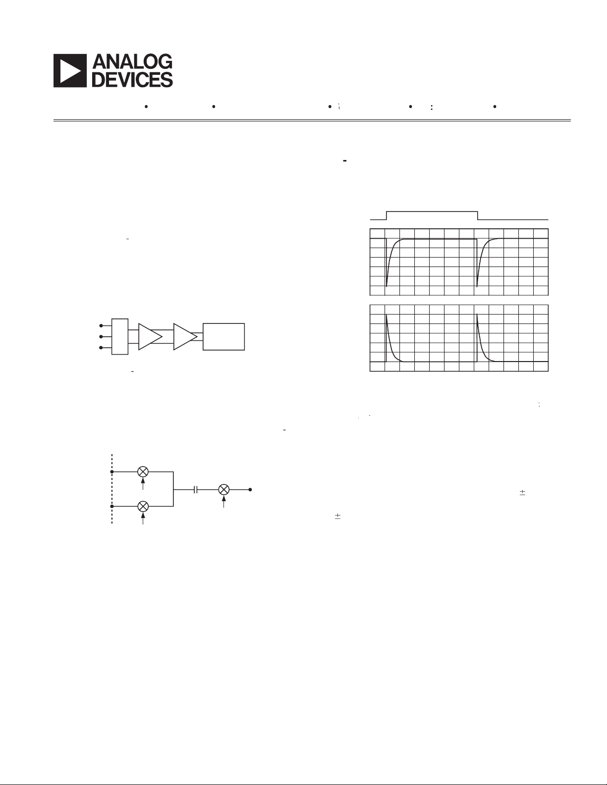
ADCs use a switched capacitor input stage to the
AIN(+)
AIN(–)
f
SAMPLE
V
BIAS
to the input voltage.
TIME, XLE – 6 Seconds
2.76
12.5
20.0
XLE – 6
27.5 35.0 42.5
2.75
2.74
2.73
–1
2.70
2.69
2.72
2.71
6
5
4
3
2
1
0
V(VPIN)
I(RIN)
L(IN1L)
= 50 pF
= 50 pF
frequency, differential input voltage, and capacitor size,
the PGA is on a range setting other than
V,
the
tance and capacitance that may be used. Excessive
values of R and C can result in ADC gain errors as a result
BUF
when C = 0 while on
the 2.56 V range.
ADCs
Page 2
–2
–
for 1 ppm (20-bit) gain error with
for protection or for ltering. In these situations an input
er to drive this dynamic load is a dif cult task, so one is
the buffer are stringent; it must have high open-loop gain
to maintain the sub ppm/
temperature, and it must have suf cient bandwidth to
ADCs
for some time (for example, on the AD7714), but there
the input voltage range. On the AD7714 the input was
V
DD
V
DD
– 1.5V
V
DD
V
DD
– 100mV
50mV
GND
100mV
GND
INPUT
RANGE
INPUT
RANGE
a. PMOS Input b. Rail-to-Rail Input
With a PMOS differential pair as the input structure, the
but cannot accept signals near ground.
Attempts have been made to use both PMOS and NMOS
Another attempt at avoiding this problem is to partition
the sampling period so that the buffer is used to charge
the capacitor to approximately the correct value, and is
then bypassed for completing the charging. However,
this method still requires dynamic current to be sourced
from the signal, and this current varies with buffer offset,
the sampling instant, so the allowable source impedance
the input voltage level. This switching is synchronized
with the modulator sampling frequency.
the signal is near ground and an NMOS pair when the
the two input stages. This allows almost complete remov-
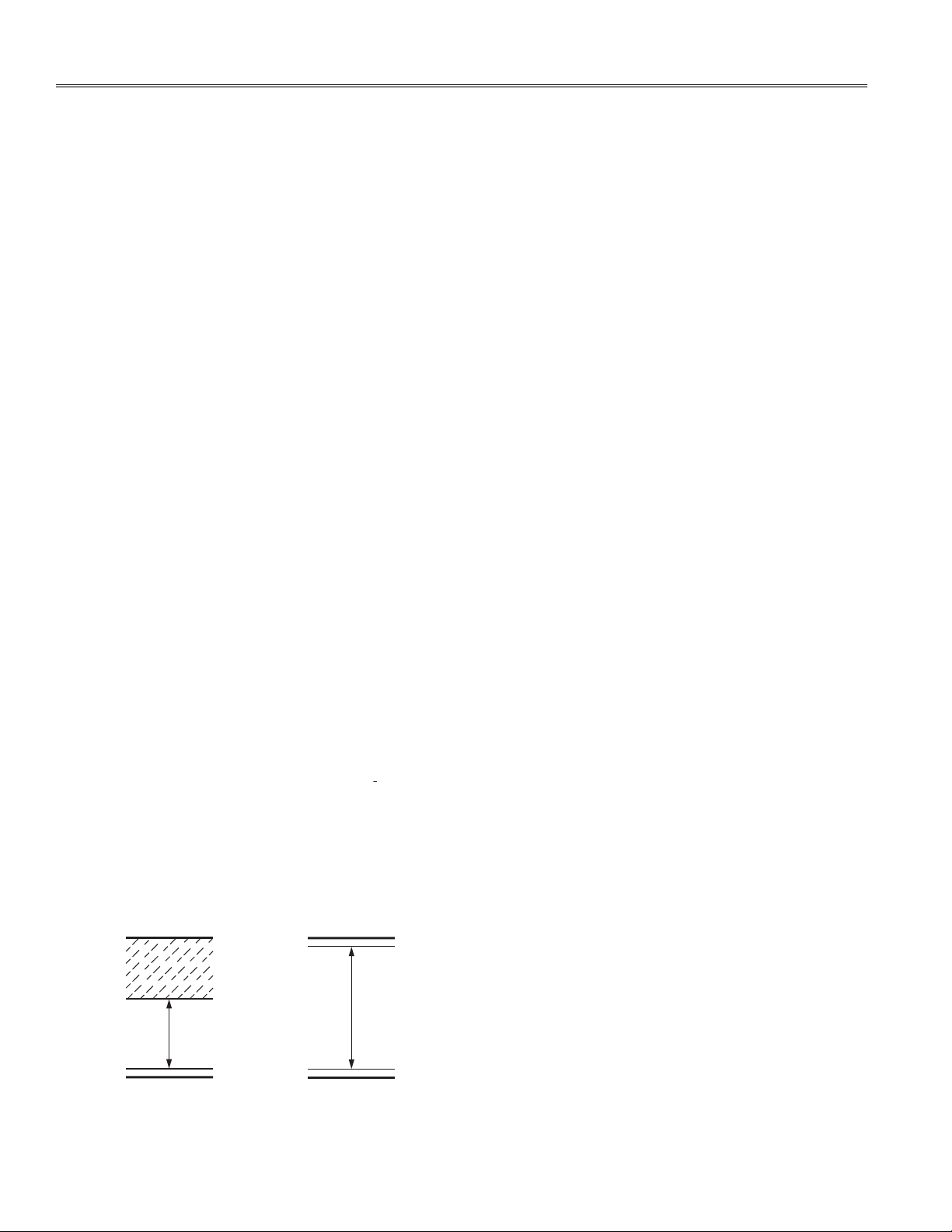
within 100 mV above ground and 100 mV below V
AV
+ 30 mV, but it must be low impedance.
Page 3

–3
–
AD7718 or CH2 bit in CONFIG[6] = 0 on AD7709.) In this
there are no gain error concerns with driving the switched
this is unlikely to cause too many problems. (This feature
the buffer. Any offset errors within the buffer are auto-
tive compared to external op amps.
and GND as the bridge excitation voltages
to the ADC reference inputs. For other circuit con gura-
tions, a reference such as the AD780 is capable of driving
the ADC load directly. If the reference is generated by a
to
which shows the AD7719 main ADC connected directly to
AD7719
EXCITATION VOLTAGE = 5V
OUT–
OUT+
IN+
IN–
AIN1
AIN2
GND PWRGND
P1
I1
10k
6k
REFIN(+)
REFIN(–)
MAIN
ADC
V
DD
AUX
ADC
200A
tance strain gage sensor is made possible by the on-chip
Page 4

–4
–
 Loading...