

Page 1

WebConsole & Programming Guide
NI Series
NetLinx Integrated Controllers
NI-700/900
NI-2000/3000/4000
NI-2100/3100/4100
NXC-ME260/64
NetLinx Integrated Controllers
Last Revised: 4/24/2007
Page 2

AMX Limited Warranty and Disclaimer
All products returned to AMX require a Return Material Authorization (RMA) number. The RMA number is
obtained from the AMX RMA Department. The RMA number must be clearly marked on the outside of each
box. The RMA is valid for a 30-day period. After the 30-day period the RMA will be cancelled. Any shipments
received not consistent with the RMA, or after the RMA is cancelled, will be refused. AMX is not responsible
for products returned without a valid RMA number.
Warranty Repair Policy
• AMX will repair any defect due to material or workmanship issues during the applicable warranty period at no cost to the AMX
Authorized Partner., provided that the AMX Authorized Partner is responsible for in-bound freight and AMX is responsible for
out-bound ground freight expenses.
• The AMX Authorized Partner must contact AMX Technical Support to validate the failure before pursuing this service.
• AMX will complete the repair and ship the product within five (5) business days after receipt of the product by AMX. The AMX
Authorized Partner will be notified if repair cannot be completed within five (5) business days.
• Products repaired will carry a ninety (90) day warranty or the balance of the remaining warranty, whichever is greater.
• Products that are returned and exhibit signs of damage or unauthorized use will be processed under the Non-Warranty Repair
Policy.
• AMX will continue to provide Warranty Repair Services for products discontinued or replaced by a Product Discontinuance
Notice.
Non-Warranty Repair Policy
• Products that do not qualify to be repaired under the Warranty Repair Policy due to age of the product or Condition of the product may be repaired utilizing this service.
• The AMX Authorized Partner must contact AMX Technical Support to validate the failure before pursuing this service.
• Non-warranty repair is a billable service.
• Products repaired under this policy will carry a ninety (90) day warranty on material and labor.
• AMX will notify the AMX Authorized Partner with the cost of repair, if cost is greater than the Standard Repair Fee, within five (5)
days of receipt.
• The AMX Authorized Partner must provide a Purchase Order or credit card number within five (5) days of notification, or the
product will be returned to the AMX Authorized Partner.
• The AMX Authorized Partner will be responsible for in-bound and out-bound freight expenses.
• Products will be repaired within ten (10) business days after AMX Authorized Partner approval is obtained.
• Non-repairable products will be returned to the AMX Authorized Partner with an explanation.
• See AMX Non-Warranty Repair Price List for minimum and Standard Repair Fees and policies.
Page 3

Table of Contents
Table of Contents
Overview ............................................................................................................1
NetLinx Integrated Controllers ................................................................................. 1
About This Document ............................................................................................... 1
Related Documents................................................................................................... 2
Quick Setup and Configuration Overview ................................................................ 2
Installation Procedures .................................................................................................... 2
Configuration and Communication.................................................................................. 2
Update the On-board Master and Controller Firmware .................................................. 3
Configure NetLinx Security on the NI Controller ............................................................ 3
Initial Configuration and Firmware Upgrade ......................................................5
Before You Start ....................................................................................................... 5
Using the ID Button to Change the Master Device Value ......................................... 5
Obtaining the NI Controller’s IP Address (using DHCP)............................................ 6
Assigning a Static IP to the NI Controller ................................................................. 8
Communicating Via an IP .......................................................................................... 9
Verifying the Firmware Version On the Master ...................................................... 11
Upgrading the On-board Master Firmware via an IP .............................................. 12
Upgrading the NI Controller Firmware Via IP ......................................................... 14
If The Connection Fails .................................................................................................. 17
Upgrading NXC Card Firmware Via IP .................................................................... 17
Resetting the Factory Default System and Device Values ...................................... 19
Onboard WebConsole User Interface ...............................................................21
WebConsole UI Overview ....................................................................................... 21
Accessing the WebConsole ........................................................................................... 22
Device Tree............................................................................................................. 22
Device Network Settings Pages.............................................................................. 23
WebConsole - WebControl Options .................................................................25
Manage WebControl Connections .......................................................................... 25
Compression Options.................................................................................................... 25
WebConsole - Security Options ........................................................................27
Security Overview................................................................................................... 27
Default Security Configuration ...................................................................................... 28
Login Rules.................................................................................................................... 28
User Name and Password Rules .................................................................................... 28
System Security - System Level............................................................................... 29
System Level Security - System Security Settings ......................................................... 29
NI Series WebConsole & Programming Guide
i
Page 4

Table of Contents
System Security Access Options .............................................................................. 30
Accepting Changes ....................................................................................................... 31
System Level Security - IPSec Security Settings ............................................................ 31
Configuring Settings ..................................................................................................... 32
Uploading an Configuration File.................................................................................... 32
Managing Certificate Files............................................................................................. 32
AMX IPSec Configuration file ........................................................................................ 32
System Security - Group Level ................................................................................ 33
Adding a New Group .................................................................................................... 33
Group and User Security Access Options ................................................................ 34
Viewing Group Security Settings Details ....................................................................... 36
Modifying the Properties of an Existing Group............................................................. 36
Deleting a Group........................................................................................................... 37
System Security - User Level ................................................................................... 38
Adding a New User ....................................................................................................... 38
Viewing and Editing User Security Settings .................................................................. 39
Deleting a User ............................................................................................................. 39
WebConsole - System Options .........................................................................41
System Overview .................................................................................................... 41
System - Manage System ........................................................................................ 41
Manage System - System Number .......................................................................... 42
Changing the System Number On the Master............................................................... 42
Using Multiple Netlinx Masters ..................................................................................... 42
Manage System - Control/Emulate Options............................................................ 42
Controlling or Emulating a System Device .................................................................... 43
Manage System - Diagnostics Options.................................................................... 46
Enabling Diagnostics On a Selected System Device...................................................... 46
Diagnostics Options Definitions .................................................................................... 49
Disabling all Diagnostic Options For a Device............................................................... 50
Creating and Recalling Diagnostics Presets................................................................... 50
Manage System - Server Options............................................................................ 51
Port Settings ................................................................................................................. 51
Server Port Settings ...................................................................................................... 52
SSL Certificate Options ................................................................................................. 53
Creating an SSL Server Certificate ................................................................................ 53
SSL Certificate Entries ................................................................................................... 54
Displaying SSL Server Certificate Information ............................................................... 55
Creating a Request for an SSL Certificate ..................................................................... 55
Self-Generating an SSL Certificate ................................................................................ 55
Regenerating an SSL Server Certificate Request........................................................... 55
ii
NI Series WebConsole & Programming Guide
Page 5

Table of Contents
Exporting an SSL Certificate Request ........................................................................... 56
Importing an SSL Certificate ......................................................................................... 57
Manage System - Clock Manager Options .............................................................. 58
Setting the Mode for the Clock Manager ..................................................................... 58
Setting Daylight Savings Rules ...................................................................................... 59
Selecting a Custom NIST Server ................................................................................... 60
Adding a Custom NIST Server To the List ..................................................................... 60
Clock Manager NetLinx Programming API.................................................................... 61
System - Manage License........................................................................................ 61
Adding A New License .................................................................................................. 61
Removing a License....................................................................................................... 62
System - Manage NetLinx ....................................................................................... 63
System - Manage Devices ....................................................................................... 65
Manage Devices - Device Options .......................................................................... 65
Configuring Device Binding Options ............................................................................. 65
Managing Device Modules ............................................................................................ 66
Manage Devices - Bindings..................................................................................... 67
Configuring Application-Defined Devices ..................................................................... 68
Application Devices and Association Status .................................................................. 69
Viewing Physical Device Properties............................................................................... 70
Manage Devices - User-Defined Devices ................................................................ 71
Adding a User-Defined Device ...................................................................................... 71
Manage Devices - View All Active Devices ............................................................. 73
Searching For All Compatible Duet Modules for a Selected Device ............................. 73
Viewing Physical Device Properties............................................................................... 74
Manage Devices - Manage Polled Ports.................................................................. 75
Editing Polled Port Settings .......................................................................................... 75
Programming ....................................................................................................77
Overview ................................................................................................................ 77
Master Send_Commands ........................................................................................ 77
Master IP Local Port Send_Commands ................................................................... 78
LED Disable/Enable Send_Commands .................................................................... 79
Port Assignments By NI Model .................................................................................... 79
RS232/422/485 Ports Channels .............................................................................. 79
RS-232/422/485 Send_Commands ........................................................................ 80
RS-232/422/485 Send_String Escape Sequences.................................................... 83
IR / Serial Ports Channels ....................................................................................... 84
IR RX Port Channels ................................................................................................ 84
IR/Serial Send_Commands ...................................................................................... 84
NI Series WebConsole & Programming Guide
iii
Page 6

Table of Contents
Input/Output Send_Commands .............................................................................. 90
Terminal (Program Port/Telnet) Commands .....................................................91
Overview ................................................................................................................ 91
Establishing a Terminal Connection Via the Program Port...................................... 91
PC COM Port Communication Settings ......................................................................... 92
NetLinx Integrated Controllers - Port Assignments....................................................... 92
Establishing a Terminal Connection Via Telnet ....................................................... 92
Terminal Commands ............................................................................................... 93
ESC Pass Codes ........................................................................................................... 106
Accessing the Security Configuration Options...................................................... 107
Setup Security Menu............................................................................................. 108
Security Options Menu................................................................................................ 109
Edit User Menu............................................................................................................ 110
Edit Group Menu......................................................................................................... 110
Access Rights Menu..................................................................................................... 111
Adding a Group........................................................................................................... 111
Edit Group Menu: Add Directory Association ............................................................. 112
Default Security Configuration .................................................................................... 113
Logging Out of a Terminal Session ....................................................................... 113
Notes on Specific Telnet/Terminal Clients ............................................................ 114
WindowsTM Client Programs ...................................................................................... 114
Linux Telnet Client....................................................................................................... 114
Appendix A: IPSec Configuration File .............................................................115
IPSec Config file.................................................................................................... 115
Internet Key Exchange (IKE) ................................................................................. 116
ikeAddPeerAuth ......................................................................................................... 116
ikeSetProp .................................................................................................................. 118
ikeSetPropAttrib ........................................................................................................ 119
Security Policy Database (SPD) ............................................................................. 120
spdAddTransport ....................................................................................................... 120
SpdAddTunnel ............................................................................................................ 121
SpdAddBypass ........................................................................................................... 122
SpdAddDiscard .......................................................................................................... 123
SpdSetProp ................................................................................................................ 124
SpdSetPropAttrib ....................................................................................................... 128
spdSetSA .................................................................................................................... 129
Manual Key Manager (MKM) ................................................................................ 130
mkmAddBypass .......................................................................................................... 130
mkmAddDiscard ......................................................................................................... 131
iv
NI Series WebConsole & Programming Guide
Page 7

Table of Contents
mkmAddTransport ..................................................................................................... 132
mkmAddTunnel .......................................................................................................... 133
mkmSetInboundAH .................................................................................................... 134
mkmSetInboundESP ................................................................................................... 135
mkmSetOutboundAH ................................................................................................. 136
mkmSetOutboundESP ................................................................................................ 137
Sample IPSec Configuration File ........................................................................... 138
IPSec Web Configuration Interface....................................................................... 139
Appendix B: Clock Manager NetLinx Programming API ................................141
Types/Constants ................................................................................................... 141
Library Calls .......................................................................................................... 142
NI Series WebConsole & Programming Guide
v
Page 8

Table of Contents
vi
NI Series WebConsole & Programming Guide
Page 9

Overview
NetLinx Integrated Controllers
NetLinx Integrated Controllers (Masters) can be programmed to control RS-232/422/485, Relay, IR/
Serial, and Input/Output devices using the NetLinx Studio application (version 2.4 or higher).
NetLinx Integrated Controllers
NI-700 (FG2105-03) NI-900 (FG2105-09)
NI-2000 (FG2105-01) NI-2100 (FG2105-04)
NI-3000 (FG2105-02) NI-3100 (FG2105-05)
NI-4000 (FG2105) NI-4100 (FG2105-06)
NXC-ME260/64 (FG2010-64)
These NI Controllers feature an on-board Web Console which allows you to connect to the NI Controller
via a web browser and make various configuration and security settings.
The Web Console is described in this document (starting with the Onboard WebConsole User
Interface section on page 21).
These NI Controllers are Duet-compatible and can be upgraded via firmware. Duet is a dual-interpreter
firmware platform from AMX which combines the proven reliability and power of NetLinx with the
extensive capabilities of the Java
of a system that includes the NI-900 and other third party devices by standardizing device and function
definitions, defaulting touch panel button assignments, and controlling feedback methods.
Dynamic Device Discovery makes integration even easier by automatically identifying and
communicating with devices which support this new beaconing technology.
Refer to the Manage Devices - Device Options section on page 65 for more detailed information on the
use of Dynamic Device Discovery (DDD).
Overview
®
MicroEdition (JavaME) platform. Duet simplifies the programming
About This Document
This document describes using the on-board Web Console, as well as NetLinx send commands and
terminal communications to configure the NI Controllers:
Each major section of the Web Console is described in a separate section of this document.
Refer to:
the Onboard WebConsole User Interface section on page 21,
the WebConsole - WebControl Options section on page 25,
the WebConsole - Security Options section on page 27, and
the WebConsole - System Options section on page 41).
The Initial Configuration and Firmware Upgrade section (page 5) describes upgrading the
firmware on NI Controllers.
The Programming section (page 77) lists and defines the NetLinx send commands that are
supported by these NI Controllers.
The Terminal (Program Port/Telnet) Commands section (page 91) describes the commands
and options available via either a Program Port (RS232) or Telnet terminal session with the NI
Controller.
NI Series WebConsole & Programming Guide
1
Page 10

Overview
Related Documents
For detailed descriptions of NI Controller hardware, including specifications, port assignments,
installation procedures, connection and wiring information, refer to the Hardware Ref erence Guide for
your Master:
Related Documents
Title
NXI-700/900 NetLinx Integrated Controllers - Hardware Reference Guide
NXI-x000 NetLinx Integrated Controllers - Hardware Reference Guide (NI-2000, NI-3000, NI-4000)
NXI-x100 NetLinx Integrated Controllers - Hardware Reference Guide (NI-2100, NI-3100, NI-4100)
NXC-ME260/64 NetLinx Master-Ethernet Card/Module - Hardware Reference Guide
NetLinx CardFrame, Control Cards, and NetModules Instruction Manual
NetLinx Studio v2.4 or higher Instruction Manual
NetLinx Programming Language Reference Guide
All product documentation is available to view or download from www.amx.com.
Quick Setup and Configuration Overview
Installation Procedures
The general steps involved with most common installations of this device include:
Unpack and confirm the contents of box (see the Specifications tables in the Hardware
Reference Guide for each Controller).
Connect all rear panel components and supply power to the NI Controller from the external
power supply.
Configuration and Communication
The general steps involved with setting up and communicating with the NI Controllers’ on-board Master.
In the initial communication process:
Set the communication speed on the front Configuration DIP switch (default = 38400).
Connect and communicate with the on-board Master via the Program port.
Set the System Value being used with the on-board Master.
Re-assign any Device values.
You can then either get a DHCP Address for the on-board Master or assign a Static IP to the
on-board Master.
Once the IP information is determined, rework the parameters for Master Communication in
order to connect to the on-board Master via the Ethernet and not the Program port.
2
NI Series WebConsole & Programming Guide
Page 11

Update the On-board Master and Controller Firmware
Before using your new NI unit, you must first update your NetLinx Studio to the most recent
release.
Upgrade the on-board Master firmware through an IP Address via the Ethernet connector
(Upgrading the On-board Master Firmware via an IP section on page 12) (IP
recommended).
Upgrade the Integrated Controller firmware through an IP Address via the Ethernet connector
(Upgrading the NI Controller Firmware Via IP section on page 14) (IP recommended).
Configure NetLinx Security on the NI Controller
Setup and finalize your NetLinx Security Protocols (WebConsole - Security Options section
on page 27).
Program your NI Controller (Programming section on page 77).
Overview
NI Series WebConsole & Programming Guide
3
Page 12

Overview
4
NI Series WebConsole & Programming Guide
Page 13

Initial Configuration and Firmware Upgrade
Initial Configuration and Firmware Upgrade
This section describes using the NetLinx Studio software application to perform the initial configuration
of the Master, as well as upgrading the firmware for various Master components.
NetLinx Studio is used to setup a System number, obtain/assign the IP/URL for the connected
NI Controller, and transfer firmware Kit files to the Master.
NetLinx Studio is available to download (free of charge) from www.amx.com.
Before commencing, verify you are using the latest firmware Kit file (this file contains
both the NI Integrated Controller and on-board Master firmware.
The NI-4000/3000/2000 Kit file begins with 2105_X000.
The NI-4100/3100/2100 Kit file begins with 2105_04_X100.
The NI-700/900 Kit file begins with 2105_03_NI-X00 and 2105_09_NI-X00
respectively.
Before You Start
1. Verify you have the latest version of NetLinx Studio on your PC. Use the Web Update option in
NetLinx Studio’s Help menu to obtain the latest version. Alternatively, go to www.amx.com and
login as a Dealer to download the latest version.
2. Verify that an Ethernet/ICSNet cable is connected from the NI Controller to the Ethernet Hub.
3. Connect an programming cable (RS-232) from the Program Port on the NI Controller to a COM
port on the PC being used for programming.
4. Verify that any control cards (NI-4000 and NI-4100 only) are inserted and their respective
connectors are attached to the rear of the NI Controller before continuing.
5. Verify that the NI Controller is powered On.
Using the ID Button to Change the Master Device Value
The steps described and the dialogs shown in this section are in the NetLinx Studio application.
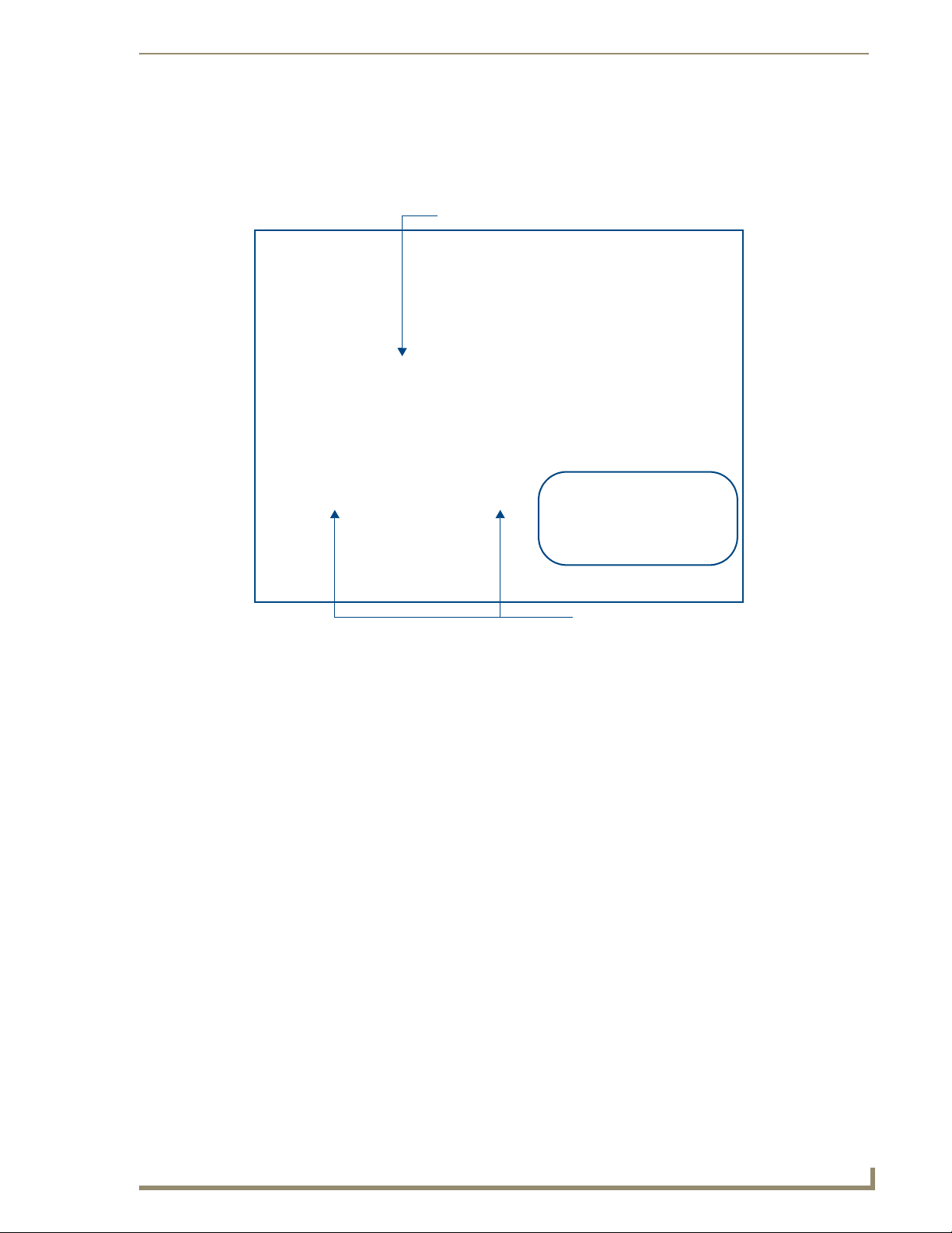
1. Access the Device Addressing dialog (FIG. 1) by selecting Diagnostics > Device Addressing.
Enter the Master’s new Device value
Assign the new value to the Master
A
FIG. 1 NetLinx Studio: Device Addressing dialog (using the ID mode to set the NI Controller’s device value)
2. In the Device field (A in FIG. 1), enter the new value for the NI Controller (range = 0 - 32767).
3. Press the Start Identify Mode button (B in FIG. 1).
B
NI Series WebConsole & Programming Guide
5
Page 14

Initial Configuration and Firmware Upgrade
This action causes the *Not Active* message (in red) to display a Waiting...Press Cancel to Quit
message (in green). This message indicates that Studio is waiting to detect the device value of the
NI Controller associated with the ID button.
4. Press the NI Controller’s ID button to read the device value of the NI Controller, and assign it to the
new value entered in step 2.
Once the swap has been successfully made, a red Successful Identification Made field appears.
The previous Device and System numbers of the NI Controller are displayed below the red
field.
Example: Previous D:S=32002:1,
where 32002 represents the previous device value of the
represents the
Obtaining the NI Controller’s IP Address (using DHCP)
Verify there is an active Ethernet connection on the NI Controller’s Ethernet port
before beginning these procedures.
1. In NetLinx Studio, select Diagnostics > Network Addresses from the Main menu to access the
Network Addresses dialog (FIG. 2).
NI Controller (D) and 1
NI Controller’s System value (S).
System Address
reflects the value
set in the Device
Addressing tab
Used to obtain a
Dynamic (DHCP)
IP Address
FIG. 2 NetLinx Studio: Network Addresses dialog (for a DHCP IP Address)
2. Verify that both the System number corresponds to the System value previously assigned within the
Device Addressing tab and that zero (0) is entered into the Device field.
The system value must correspond to the Device Address entered in the Device
Addressing dialog. Refer to the Manage System - System Number section on
page 42 for more detailed instructions on setting a system value.
3. Click the Get IP Information button to configure the on-board Master for DHCP usage and then
read the IP Address obtained from the DHCP Server.
DO NOT enter ANY IP information at this time; this step only gets the System Master
to recognize that it should begin using an obtained DHCP Address.
6
NI Series WebConsole & Programming Guide
Page 15

Initial Configuration and Firmware Upgrade
4. Note the obtained IP Address (read-only). This information is later entered into the Master
Communication Settings dialog and used by NetLinx Studio v 2.x to communicate to the NI
Controller via an IP. This address is reserved by the DHCP server and then given to the Master.
If the IP Address field is empty, give the Master a few minutes to negotiate a DHCP
Address with the DHCP Server, and try again. The DHCP Server can take anywhere
from a few seconds to a few minutes to provide the Master with an IP Address.
5. Ver i f y t h a t NetLinx appears in the Host Name field (if not, then enter it in at this time).
6. Click the Use DHCP radio button from the IP Address section.
7. Click the Set IP Information button to retain the IP Address from the DHCP server and assign it to
the on-board Master. A popup window then appears to notify you that Setting the IP information
was successful and it is recommended that the Master be rebooted.
8. Click OK to accept the change to the new IP/DNS information.
9. Click the Reboot Master button and select Ye s to close the Network Addresses dialog.
10. Click Reboot (from the Tools > Reboot the Master Controller dialog) and wait for the System
Master to reboot and retain the newly obtained DHCP Address.
The STATUS and OUTPUT LEDs should begin to alternately blink during the incorporation. Wait
until the STATUS LED is the only LED to blink.
11. Press Done once until the Master Reboot Status field reads *Reboot of System Complete*.
Verify that these IP values are also entered into the related fields within either the
IP Settings section of the System Connection page (on the touch panel) or within the
Address field on the web browser.
12. Complete the communication process by continuing on to the Communicating Via an IP section on
page 9.
NI Series WebConsole & Programming Guide
7
Page 16

Initial Configuration and Firmware Upgrade
Assigning a Static IP to the NI Controller
Verify there is an active Ethernet connection on the Ethernet port of the Master
before beginning these procedures.
1. In NetLinx Studio, select Diagnostics > Network Addresses from the Main menu to access the
Network Addresses dialog (FIG. 3).
System Address
reflects the value
set in the Device
Addressing tab
Used to retain an
IP Address
FIG. 3 Network Addresses dialog (for a pre-obtained Static IP Address)
2. Verify that both the System number corresponds to the System value previously assigned within the
Device Addressing tab and that zero (0) is entered into the Device field.
The system value must correspond to the Device Address previously entered in the
Device Addressing tab. Refer to the Manage System - System Number section on
page 42 for more detailed instructions on setting a system value.
3. Click the Get IP Information button to temporarily configure the on-board Master for DHCP usage
and then read the IP Address obtained from the DHCP Server.
4. Click the Specify IP Address radio button from the IP Address section. With this action, all IP
fields become editable.
5. Ver i f y t h a t NetLinx appears in the Host Name field (if not, then enter it in at this time).
6. Enter the IP Address, Subnet Mask, and Gateway information into their respective fields.
7. Click the Set IP Information button to cause the on-board Master to retain this new IP Address
(pre-obtained from the System Administrator).
8. Click OK to accept the change to the new IP/DNS information.
9. Click the Reboot Master button and select Ye s to close the Network Addresses dialog.
10. Click Reboot (from the Tools > Reboot the Master Controller dialog) and wait for the System
Master to reboot and retain the newly obtained DHCP Address.
The STATUS and OUTPUT LEDs should begin to alternately blink during the incorporation. Wait
until the STATUS LED is the only LED to blink.
11. Press Done once until the Master Reboot Status field reads *Reboot of System Complete*.
8
NI Series WebConsole & Programming Guide
Page 17

Initial Configuration and Firmware Upgrade
Verify that these IP values are also entered into the related fields within either the
IP Settings section of the System Connection page (on the touch panel) or within the
Address field on the web browser.
12. Complete the communication process by continuing on to the Communicating Via an IP section on
page 9.
Communicating Via an IP
Whether the on-board Master’s IP Address was Static Set (via the Set IP Info command) or
Dynamically obtained (via the Get IP Info command), use the IP Address information from the Network
Addresses dialog to establish communication via the Ethernet-connected Master.
1. Use NetLinx Studio to obtain the IP Address of the NI Controller from your System Administrator.
If you do not have an IP Address:
Follow the steps outlined in either the Obtaining the NI Controller’s IP Address (using
DHCP) section on page 6,
or the Assigning a Static IP to the NI Controller section on page 8.
2. Select Settings > Master Communication Settings from the Main menu to open the Master
Communication Settings dialog (FIG. 4).
FIG. 4 Assigning Master Communication Settings and TCP/IP Settings
3. Click the Communications Settings button to open the Communications Settings dialog.
4. Click on the NetLinx Master radio button (from the Platform Selection section) to indicate you are
working with a NetLinx Master (such as the NXC-ME260/64 or NI-Series of Integrated
Controllers).
5. Click on the TCP/IP radio button (from the Transport Connection Option section) to indicate you
are connecting to the Master via an IP Address.
NI Series WebConsole & Programming Guide
9
Page 18

Initial Configuration and Firmware Upgrade
6. Click the Edit Settings button (on the Communications Settings dialog) to open the TCP/IP
Settings dialog (FIG. 4). This dialog contains a series of previously entered IP Address/URLs and
their associated names, all of which are stored within Studio and are user-editable.
7. Click the New button to open the New TCP/IP Settings dialog where you can enter both a
previously obtained DHCP or Static IP Address and an associated description for the connection
into their respective fields.
8. Place a checkmark within the Automatically Ping the Master Controller to ensure availability radio
box to make sure the Master is initially responding online before establishing full communication.
9. Click OK to close the current New TCP/IP Settings dialog and return to the previous TCP/IP
Settings dialog where you must locate your new entry within the List of Addresses section.
10. Click the Select button to make that the currently used IP Address communication parameter.
11. Click OK to return to the Communications Settings dialog and place a checkmark within the
Authentication Required radio box if your Master has been previously secured with a username/
password.
12. Click on the Authentication Required radio box (if the Master is secured) and then press the User
Name and Password button to open the Master Controller User Name and Password dialog.
13. Within this dialog, you must enter a previously configured username and password (with sufficient
rights) before being able to successfully connect to the Master.
14. Click OK to save your newly entered information and return to the previous Communication
Settings dialog where you must click OK again to begin the communication process to your Master.
If you are currently connected to the assigned Master, a popup asks whether you
would want to temporarily stop communication to the Master and apply the new
settings.
15. Click Ye s to interrupt the current communication from the Master and apply the new settings.
16. Once the particular System Master is configured for communication via an IP Address, remove the
DB9 connector from the Program port on the NI on-board Master.
17. Click Reboot (from the Tools > Reboot the Master Controller dialog) and wait for the Master to
reboot.
The STATUS and OUTPUT LEDs should begin to alternately blink during the incorporation. Wait
until the STATUS LED is the only LED to blink.
18. Press Done once until the Master Reboot Status field reads *Reboot of System Complete*.
19. Click the OnLine Tree tab in the Workspace window to view the devices on the System. The default
System value is one (1).
20. Right-click the associated System number and select Refresh System. This establishes a new
connection to the specified System and populates the list with devices on that system. The
communication method is then highlighted in green on the bottom of the NetLinx Studio window.
If the connection fails to establish, a Connection Failed dialog appears.
Try selecting a different IP Address if communication fails.
Press the Retry button to reconnect using the same communication parameters.
Press the Change button to alter your communication parameters and repeat
steps 4 thru 18.
10
NI Series WebConsole & Programming Guide
Page 19

Initial Configuration and Firmware Upgrade
Verifying the Firmware Version On the Master
All NI Controllers contain both an on-board NI Master and an Integrated Controller. If you are using an
NI-4000 or NI-4100 with installed NXC cards, these will also show up within the Online Tree tab.
The on-board Master shows up within the Online Tree as 00000 NI Master
The Integrated Controller of the NI shows up as 0XXXX NI-XXXX (ex: 050001 NI-700)
Each of these components has its own corresponding firmware shown in parenthesis ().
1. After Studio has established a connection with the target Master, click on the OnLine Tree tab in
the Workspace window to view the devices on the System. The default System value is one (1).
2. Right-click the associated System number and select Refresh System. This establishes a new
connection to the specified System and populates the list with devices on that system. The
communication method is highlighted in green on the bottom of the NetLinx Studio window.
The current installed firmware version of the on-board NI Master is displayed to the
right of the device within the Online Tree tab as 00000 NI Master.
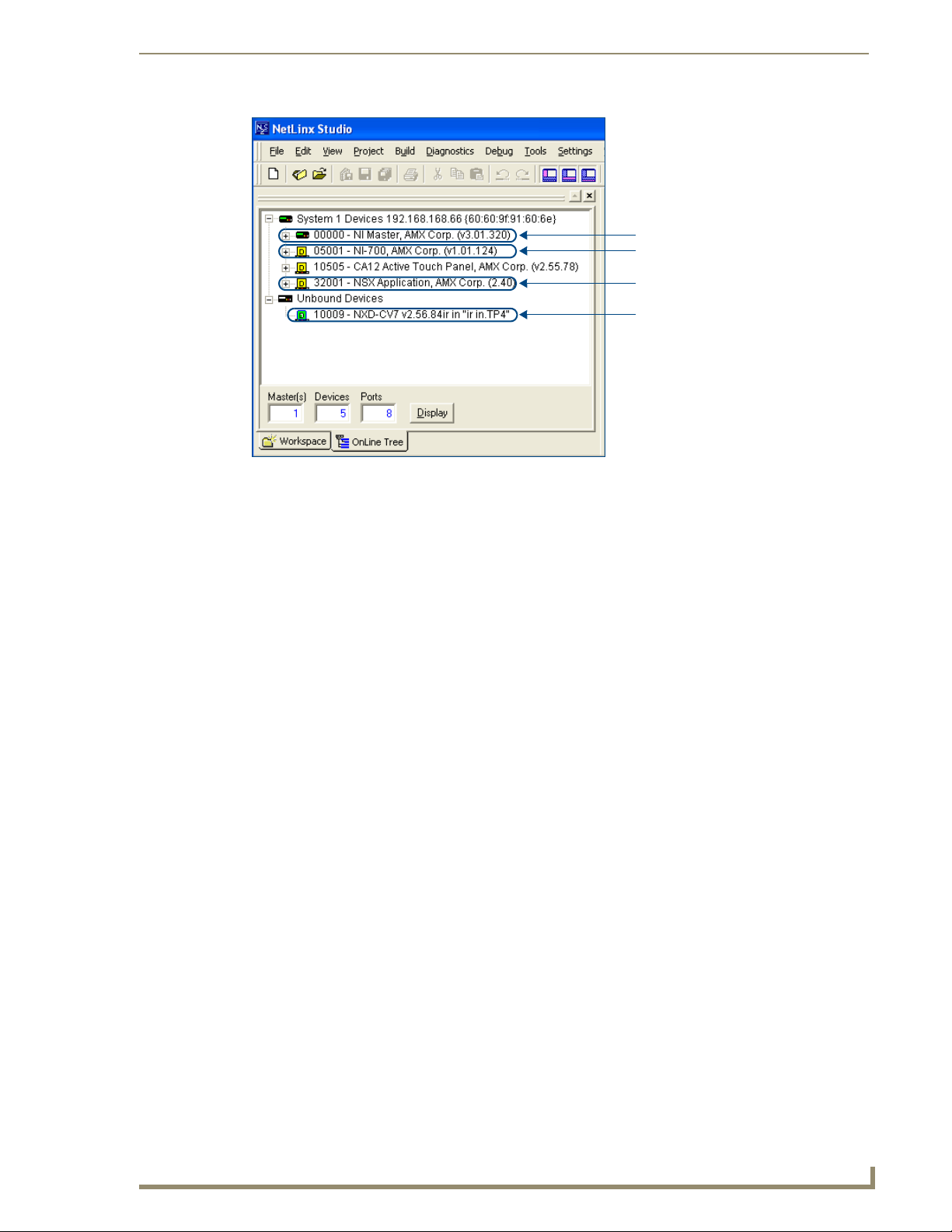
3. After the Communication Verification dialog indicates active communication between the PC and
the Master, verify the NetLinx Master (00000 NI Master) appears within the OnLine Tree tab of
the Workspace window (FIG. 5).
The default NI Master value is zero (00000) and cannot be changed.
On-board NI Master
Control cards (NI-4x00 ONLY)
NetLinx Integrated Controller
NetLinx Studio version
Unbound Dynamic Device
FIG. 5 Sample NetLinx Workspace window (showing OnLine Tree tab)
4. If either the on-board NI Master or Integrated Controller is not the latest firmware version, follow
the procedures outlined in the following sections to obtain these Kit files from www.amx.com and
then transfer the new firmware Kit files to the device.
NI Series WebConsole & Programming Guide
11
Page 20

Initial Configuration and Firmware Upgrade
Upgrading the On-board Master Firmware via an IP
The on-board Master firmware Kit file is not the same as the Integrated Controller Kit file. Below is a
table outlining the current sets of on-board Master and Integrated Controller Kit files used by the NISeries of products:
Firmware Kit File usage for NI Controllers
NI-4100 On-board Master Kit file: 2105_04_NI-X100_Master
Integrated Controller Kit file: 2105_04_NI-X100
NI-3100 On-board Master Kit file: 2105_04_NI-X100_Master
Integrated Controller Kit file: 2105_04_NI-X100
NI-2100 On-board Master Kit file: 2105_04_NI-X100_Master
Integrated Controller Kit file: 2105_04_NI-X100
NI-4000 On-board Master Kit file: 2105_NI-X000_Master
Integrated Controller Kit file: 2105_NI-X000
NI-3000 On-board Master Kit file: 2105_NI-X000_Master
Integrated Controller Kit file: 2105_NI-X000
NI-2000 On-board Master Kit file: 2105_NI-X000_Master
Integrated Controller Kit file: 2105_NI-X000
NI-700 On-board Master Kit file: 2105-03_NI-X000_Master
Integrated Controller Kit file: 2105-03_NI_X00
NI-900 On-board Master Kit file: 2105-03_NI-X000_Master
Integrated Controller Kit file: 2105-09_NI_X00
Only Master firmware Kit files use the word _Master in the Kit file name.
1. Follow the procedures outlined within the Communicating Via an IP section on page 9 to connect to
the target NI device via the web.
2. After NetLinx Studio has established a connection to the target Master, click the OnLine Tree tab
of the Workspace window to view the devices on the System. The default System value is one (1).
3. Right-click the associated System number and select Refresh System. This establishes a new
connection to the specified System and populates the list with devices on that system. The
communication method is highlighted in green on the bottom of the NetLinx Studio window.
4. After the Communication Verification dialog window verifies active communication between the
PC and the Master, verify the NetLinx Master (00000 NI Master) appears in the OnLine Tree tab
of the Workspace window. The default NI Master value is zero (00000).
First upgrade of the on-board Master using the Master’s Kit file.
The Integrated Controller can later be upgraded using the Controller’s Kit file.
BOTH Kits should be used when upgrading any firmware associated with the
Integrated Controllers.
5. If the on-board Master firmware being used is not current, download the latest Kit file by first
logging in to www.amx.com and then navigating to Tech Center > Firmware Files, where you can
locate the desired file from within the NetLinx section of the web page.
6. Click on the desired Kit file link and after you’ve accepted the Licensing Agreement, verify you
have downloaded the correct NI Master firmware (Kit) file to a known location.
12
NI Series WebConsole & Programming Guide
Page 21
Initial Configuration and Firmware Upgrade
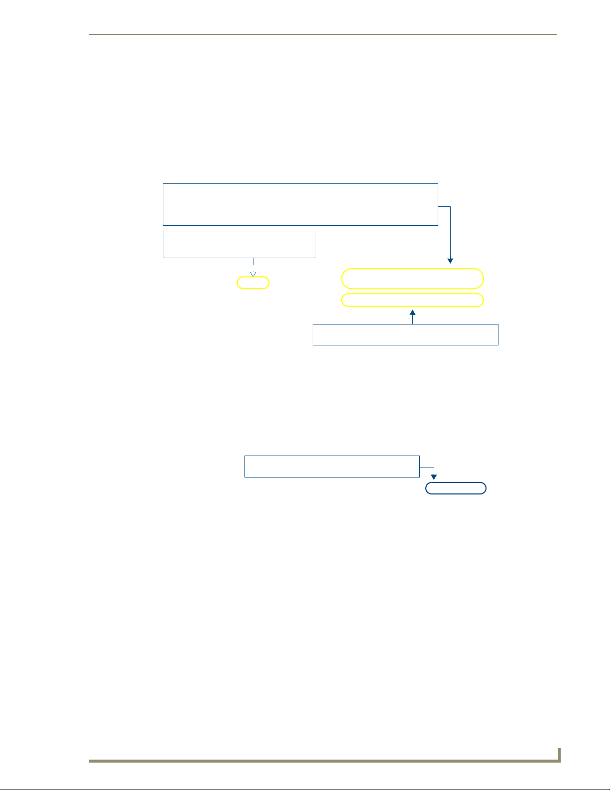
7. In NetLinx Studio, select Tools > Firmware Transfers > Send to NetLinx Device to open the
Send to NetLinx Device dialog (FIG. 6). Verify the target’s System number matches the value listed
within the active System folder in the OnLine Tree tab of the Workspace.
The Device number is always 0 for the NI Master.
Selected Master firmware file
Description field for
selected Kit file
Firmware download
status
Device and System Number
must match the Device and System values
listed in the Workspace window
FIG. 6 Send to NetLinx Device dialog (showing on-board NI_Master firmware update via IP)
8. Select the NI Master’s Kit file from the Files section (FIG. 6).
The Kit file for the NI-2000/3000/4000 Masters begins with 2105_NI-X000_Master.
The Kit file for the NI-2100/3100/4100 Masters begins with 2105_04_NI-X100_Master.
The Kit file for the NI-700/900 Masters begins with 2105-03_NI-X000_Master.
Do not use the 2105-03_NI_Master Kit file on anything other than an NI-700/900, since each
Master Kit file is specifically configured to function on a specific NI unit.
9. Enter the System number associated with the target Master (listed in the OnLine Tree tab of the
Workspace window) and verify the Device number value. The Port field is disabled.
10. Click the Reboot Device checkbox to reboot the NI unit after the firmware update process is
complete.
11. Click Send to begin the transfer. The file transfer progress is indicated on the bottom-right of the
dialog (FIG. 6).
NI Series WebConsole & Programming Guide
13
Page 22

Initial Configuration and Firmware Upgrade
Only upon the initial installation of a new Kit file to an on-board Master will there
be a error message displayed indicating a failure of the last component to
successfully download.
This is part of the NI Master update procedure and requires that the firmware be
reloaded after a reboot of the unit. This consecutive process installs the final
component of the new Kit file.
12. After the last components fails to install, click Done.
13. Click Reboot (from the Tools > Reboot the Master Controller dialog) and wait for the System
Master to reboot.
The STATUS and OUTPUT LEDs should begin to alternately blink during the incorporation. Wait
until the STATUS LED is the only LED to blink.
14. Press Done once until the Master Reboot Status field reads *Reboot of System Complete*.
15. Repeat steps 5 - 9 again (the last component will now successfully be installed).
16. Click Close once the download process is complete.
The OUTPUT and INPUT LEDs alternately blink to indicate the on-board Master is
incorporating the new firmware. Allow the Master 20 - 30 seconds to reboot and fully
restart.
17. Right-click the System number and select Refresh System. This establishes a new connection to the
System and populates the list with the current devices (and their firmware versions) on your system.
Upgrading the NI Controller Firmware Via IP
1. Follow the procedures outlined within the Communicating Via an IP section on page 9 to connect to
the target NI device via the web.
2. After Studio has established a connection to the target Master, click the OnLine Tree tab of the
Workspace window to view the devices on the System. The default System value is one (1).
3. Right-click the associated System number and select Refresh System. This establishes a new
connection to the specified System and populates the list with devices on that system. The
communication method is highlighted in green on the bottom of the NetLinx Studio window.
4. After the Communication Verification dialog window verifies active communication between the
PC and the NI unit, verify the Integrated Controller appears in the OnLine Tree tab (FIG. 7) of the
Workspace window (ex: NI-4000 or NI-700). This entry is different than the NI Master which uses a
device value of 00000 (see below):
14
NI Series WebConsole & Programming Guide
Page 23
Initial Configuration and Firmware Upgrade
On-board NI Master
(NI-X000_Master) - Device 0
On-board Integrated Controller (NI-X000)
NetLinx Studio version
Unbound Dynamic Device
FIG. 7 Sample NetLinx Workspace window (showing separate NI-Master and Controller)
5. If the NI Controller firmware being used is not current, download the latest Kit file by first logging
in to www.amx.com and then navigating to Tec h Ce n ter > Firmware Files, where you can locate
the desired file from within the NI Series Device (Integrated Controller) section of the web page.
6. Click on the desired Kit file link and after you’ve accepted the Licensing Agreement, verify you
have downloaded the Integrated Controller firmware (Kit) file to a known location.
7. From within Studio, select Tools > Firmware Transfers > Send to NetLinx Device from the Main
menu to open the Send to NetLinx Device dialog (FIG. 8). Verify the target’s System number
matches the value listed within the active System folder in the OnLine Tree tab of the Workspace.
The Device must match the entry for the on-board Integrated Controller (ex: NI-4000 or
NI-700) device.
NI Series WebConsole & Programming Guide
15
Page 24

Initial Configuration and Firmware Upgrade
Selected on-board Integrated Controller firmware file
FIG. 8 Send to NetLinx Device dialog (showing on-board Integrated Controller firmware update via IP)
Firmware download
status
Device and System Number
must match the Device and System
values listed in the Workspace window
The Kit file for the Integrated Controller on the NI-2000/3000/4000 begins with
2105_NI_X000.
The Kit file for the Integrated Controller on the NI-2100/3100/4100 begins with
2105_04_NI_X100.
The Kit file for the NI-700/900 Series begins with 2105-03_NI_X000
Do not use the 2105-03_NI_X00 Kit file on anything other than an NI-700/900 since each Kit file is
specifically configured to function on a specific NI unit.
8. Select the Integrated Controller’s (_X00) from the Files section (FIG. 8).
9. Enter the System and Device numbers associated with the target Master (listed in the Workspace
window). The Port field is greyed-out.
10. Click the Reboot Device checkbox to reboot the NI unit after the firmware update process is
complete.
11. Click Send to begin the transfer. The file transfer progress is indicated on the bottom-right of the
dialog (FIG. 8).
12. Click Close once the download process is complete.
The OUTPUT and INPUT LEDs alternately blink to indicate the unit is incorporating
the new firmware. Allow the unit 20 - 30 seconds to reboot and fully restart.
16
13. Right-click the System number and select Refresh System. This establishes a new connection to the
System and populates the list with the current devices (and their firmware versions) on your system.
NI Series WebConsole & Programming Guide
Page 25

Initial Configuration and Firmware Upgrade
If The Connection Fails
If the connection fails to establish, a Connection Failed dialog appears.
Try selecting a different IP Address if communication fails.
Press the Retry button to reconnect using the same communication parameters.
Press the Change button to alter your communication parameters and repeat
steps 2 thru 11.
Upgrading NXC Card Firmware Via IP
This section applies to the NI-4000 and NI-4100 0nly.
Before beginning with this section, verify that both the on-board Master and on-board Integrated
Controller have been updated with the latest firmware and that the NetLinx cards are securely inserted
into the NI-4000 or NI-4100.
1. Follow the procedures outlined within the Communicating Via an IP section on page 9 to connect to
the target NI device via the web.
2. After NetLinx Studio has established a connection to the target Master, click the OnLine Tree tab
of the Workspace window to view the devices on the System. The default System value is one (1).
3. Right-click the associated System number and select Refresh System. This establishes a new
connection to the specified System and populates the list with devices on that system. The
communication method is highlighted in green on the bottom of the NetLinx Studio window.
4. After the Communication Verification dialog window verifies active communication between the
PC and the NI unit, verify the NetLinx NXC Control Cards appear in the OnLine Tree tab of the
Workspace window (FIG. 9).
FIG. 9 Sample NetLinx Workspace window (showing OnLine Tree tab)
If the control card firmware is not up to date; download the latest firmware file from
www.amx.com > Tech Center > Downloadable Files > Firmware Files >
NXC-XXX.
In this example, the NXC-VOL card contains out-of-date firmware and requires build
1.00.09.
NI Series WebConsole & Programming Guide
On-board NI Master
Control cards (NI-4x00 ONLY)
NetLinx Integrated Controller
NetLinx Studio version
17
Page 26

Initial Configuration and Firmware Upgrade
5. If the NXC card firmware being used is not current, download the firmware file by first logging in to
www.amx.com and then navigate to Tec h Cen t er > Firmware Files and from within the NetLinx
section of the web page locate the NXC card entries.
6. Click on the desired Kit file link and after you’ve accepted the Licensing Agreement, verify you
have downloaded the NetLinx NXC card firmware (Kit) file to a known location.
7. Verify you have downloaded the latest NetLinx Control Card firmware (Kit) file to a known
location.
8. Select Tools > Firmware Transfers > Send to NetLinx Device from the Main menu to open the
Send to NetLinx Device dialog (FIG. 10). Verify the target’s Device and System numbers matches
the value listed within the System folder in the Workspace window.
Selected Control Card
Firmware file
FIG. 10 Select Control Card firmware file for download page (via IP)
Description field for selected Kit file
Firmware download
status
System Number and Device Number
must match the System and Device values
listed in the Workspace window
9. Select the Control Card’s Kit file from the Files section (FIG. 10) (in our above example we chose
to update the NXC-VOL4 card).
10. Enter the System and Device numbers associated with the desired Master (listed in the Workspace
window). A device value of 00003 is the same as a value of 3.
11. Click the Reboot Device checkbox to reboot the NI unit after the firmware update process is
complete and then re-detect the new NXC card firmware.
12. Click Send to begin the transfer. The file transfer progress is indicated on the bottom-right of the
dialog (FIG. 10).
13. Click Close once the download process is complete.
14. Click Reboot (from the Tools > Reboot the Master Controller dialog) and wait for the System
Master to reboot.
The STATUS and OUTPUT LEDs should begin to alternately blink during the incorporation. Wait
until the STATUS LED is the only LED to blink.
15. Press Done once until the Master Reboot Status field reads *Reboot of System Complete*.
18
NI Series WebConsole & Programming Guide
Page 27

Initial Configuration and Firmware Upgrade
16. Cycle power to the Master (unplug and reconnect power to the unit).
This process of cycling power acts to reset the updated NetLinx Control Card and
detect its new firmware update. It also serves to allow the Integrated Controller to
detect and reflect the new firmware on the card to the NetLinx Studio display on the
Workspace window.
17. After Studio has establish a connection to target Master, click the OnLine Tree tab of the
Workspace window to view the devices on the System. The default System value is one (1).
18. Right-click the associated System number and select Refresh System. This establishes a new
connection to the specified System and populates the list with devices on that system.
The communication method is highlighted in green on the bottom of the NetLinx Studio window.
Resetting the Factory Default System and Device Values
1. In NetLinx Studio, access the Device Addressing dialog (FIG. 1 on page 5) by either one of these
two methods:
Right-click on any system device listed in the Workspace and select Device Addressing.
Select Diagnostics > Device Addressing from the Main menu.
2. Click the Set Device/System to Factory Default button. This resets both the system value and
device addresses (for definable devices) to their factory default settings. The system information (in
the OnLine Tree tab of the Workspace window) refreshes and then displays the new information.
By setting the system to its default value (#1), Modero panels that were set to
connect to the Master on another System value will not appear in the OnLine Tree
tab of the Workspace window.
For example: A Modero touch panel was previously set to System #2. The system is
then reset to its default setting of System #1 and then refreshed from within the
Workspace window. The panel will not reappear until the system is changed (from
within the System Connection page on the Modero) to match the new value and both
the Master and panel are rebooted.
3. Click Done to close the Device Addressing dialog.
4. Click Reboot (from the Tools > Reboot the Master Controller dialog) and wait for the System
Master to reboot.
The STATUS and OUTPUT LEDs should begin to alternately blink during the incorporation. Wait
until the STATUS LED is the only LED to blink.
5. Press Done once until the Master Reboot Status field reads *Reboot of System Complete*.
6. Click the OnLine Tree tab in the Workspace window to view the devices on the System.
The default System value is one (1).
7. Right-click the associated System number (or anywhere within the tab itself) and select Refresh
System. This establishes a new connection to the specified System and populates the list with
devices on that system.
8. Use Ctrl+S to save these changes to your NetLinx Project.
NI Series WebConsole & Programming Guide
19
Page 28

Initial Configuration and Firmware Upgrade
20
NI Series WebConsole & Programming Guide
Page 29
Onboard WebConsole User Interface
Onboard WebConsole User Interface
WebConsole UI Overview
NetLinx Masters have a built-in WebConsole that allows you to make various configuration settings via
a web browser on any PC that has access to the Master. The webconsole consists of a series of web pages
that are collectively called the "Master Configuration Manager" (FIG. 11).
System/Device info:
System (read-only): indicates the name of the System currently connected
Device: click the down-arrow to select from a list of all devices connected to this Master
Refresh: Click to refresh the Device list.
Click to Login (only required if Master Security
and HTTP Access security options are enabled
on the target Master)
Click to access the three main sections of the WebConsole
(initial view = WebControl)
Select this option to show/hide the Online Device Tree
(showing all devices currently connected to this Master)
FIG. 11 Master Configuration Manager - WebControl Page (initial view)
The webconsole is divided into three primary sections, indicated by three control buttons across the top
of the main page (FIG. 12):
FIG. 12 WebConsole Control Buttons
WebControl: This is the option that is pre-selected when the WebConsole is accessed. Use the
options in the Manage WebControl Connections page to manage G4WebControl connections
(see the WebConsole - WebControl Options section on page 25).
Security: Click to access the System Security page. The options in this page allow you to
configure various aspects of NetLinx System and Security on the Master (see the WebConsole
- Security Options section on page 27).
System: Click to access the System Details page. The options on this page allow you to view
and configure various aspects of the NetLinx System (see the WebConsole - System
Options section on page 41).
NI Series WebConsole & Programming Guide
21
Page 30

Onboard WebConsole User Interface
Accessing the WebConsole
From any PC that has access to the LAN that the target Master resides on:
1. Open a web browser nd type the IP Address of the target Master in the Address Bar.
2. Press Enter to access WebConsole for that Master. The initial view is the WebControl page
(FIG. 11).
Device Tree
Click the Show Device Tree checkbox to show/hide the online device tree, which indicates all devices
currently connected to this Master. Use the plus and minus symbols to the left of each item in the Device
Tree to expand the view to include System devices, ports and individual Port settings.
At the Port view, you can use the Device Tree to make specific port assignments (including Channel and
Level assignments) (FIG. 13).
(all Collapsed)
(System devices expanded)
(NI-700 ports expanded)
(NI-700 Port 1 expanded)
22
Opens the Network Settings
page for this device
FIG. 13 Online Device Tree
NI Series WebConsole & Programming Guide
Page 31

Onboard WebConsole User Interface
Device Network Settings Pages
Click on the blue Information (i) icon next to any device listed in the Device Tree to access the Network
Settings page for the selected device (FIG. 14).
FIG. 14 Example Network Settings page for a sample CV15 connected to the Master
Use the options on this page to view/edit the device’s network settings.
Refer to the System - Manage System section on page 41 for details.
NI Series WebConsole & Programming Guide
23
Page 32

Onboard WebConsole User Interface
24
NI Series WebConsole & Programming Guide
Page 33

WebConsole - WebControl Options
WebConsole - WebControl Options
Manage WebControl Connections
The WebControl page is accessed by clicking on the WebControl button (FIG. 15). This page allows
you to view all touch panels running the G4WebControl application.
Each G4WebControl-equipped touch panel connected to this Master is indicated by a link. Click on any
of the links to open a new G4WebControl window, displaying the selected panel, using the native
resolution of the target panel. For example, a CA15 panel link opens a new G4WebControl window at
800 x 600 resolution.
Click on any link listed here to open a new
G4WebControl window to view the indicated panel
Compression options
FIG. 15 Manage WebControl Connections page (populated with 1 compatible G4 touch panel)
To establish a secure connection between the touch panel and the target Master, the panel must be using
a valid username and password (that can be matched to a previously configured user on the target
Master) and the ICSP Connectivity option must be enabled within the System Level Security page.
Compression Options
The checkboxes at the bottom of this page allow you to choose from two compression options. Use
compression to decrease response delay when viewing G4WebControl windows over a bandwidthrestricted network, or over the Internet. By default, compression options are disabled.
Use Compression allows you to specify that the transmitted data packets be compressed. This
speeds up the visual responses from the panel by minimizing the size of the information
relayed through the web and onto the screen.
Use Low Color allows you to specify the number of colors used to display the image from the
panel be reduced. By reducing the numbers of colors, the size of the information is reduced
and the response delay is decreased.
NI Series WebConsole & Programming Guide
25
Page 34

WebConsole - WebControl Options
26
NI Series WebConsole & Programming Guide
Page 35

WebConsole - Security Options
Security Overview
The Security System Details page is accessed by clicking on the Security button. This page allows you to
view configure and modify the Master’s security settings at three levels:
System Level - changes made at this level affect the system globally.
See the System Security - System Level section on page 29 for details.
Group Level - changes made at this level affect specific User Groups.
See the System Security - Group Level section on page 33 for details.
User Level - changes made at this level affect individual Users.
See the System Security - User Level section on page 38 for details.
The default view for the option is System Level Security / System Security Settings (FIG. 16).
These tabs provide access to the three
levels of security configuration provided
(default view = System Level)
WebConsole - Security Options
FIG. 16 System Security Details Page (System Security Settings)
By default, all System-level security options are disabled.
NI Series WebConsole & Programming Guide
27
Page 36

WebConsole - Security Options
Default Security Configuration
By default, the NetLinx Master creates the following accounts, access rights, directory associations, and
security options:
Default Security Configuration
Account 1 Account 2 Group 1
Username: administrator Username: NetLinx
Password: password Password: password
Group: administrator Group: none Group: administrator
Rights: All Rights: FTP Access Rights: All
Directory Association: /* Directory Association: none Directory Association: /*
Note: The "administrator" User
account cannot be deleted or
modified with the exception of its
password. Only a user with both
Configuration access and
administrator rights can alter the
administrator’s password.
FTP Security is always enabled on the Masters.
The Admin Change Password Security option (in the Group and User Level Security Details
All other security options are disabled by default.
pages is enabled by default.
Note: The "NetLinx" User
account is compatible with
previous NetLinx Master
firmware versions. This
account is initially created by
default and can later be deleted
or modified.
Note: The "administrator" Group
account cannot be deleted or
modified.
Login Rules
There is no limit to the number of concurrent logins allowed for a single user. This allows for the
creation of a single User that is provided to multiple ICSP devices (touch panels, for example) using the
same login to obtain access to the Master.
For example, if you had 50 devices connected to a Master, you would not have to create 50 individual
user accounts-one for each device. Instead, you only need to create one which all 50 devices use for
access.
The first layer of security for the Master is to prompt a user to enter a valid username and password
before gaining access to a secured feature on the target Master.
Depending on the Security configuration, Users may be prompted to enter a valid username and
password before gaining access to various features of the WebConsole. User access is specified by the
administrator in the Group and User Level pages of the Security section.
This username and password information is also used by both G4 touch panels
(within the System Connection firmware page) and AMX software applications such
as NetLinx Studio v 2.4 to communicate securely with a Master using encrypted
communication.
User Name and Password Rules
Case-sensitive.
Must be between 4 and 20 characters.
Characters such as # (pound) & (ampersand) and ’ " (single and double quotes) are invalid
and should not be used in usernames, group names, or passwords.
28
NI Series WebConsole & Programming Guide
Page 37

WebConsole - Security Options
System Security - System Level
System Level Security options provide authorized users the ability to alter the current security options of
the entire system assigned to the Master.
There are two System Level Security pages, accessible via the System Security Settings and Security
Settings links in the System Level Tab:
The. Security Settings option is only available on the NI-700/900 and NI-X100
series.
System Level Security - System Security Settings
Click the System Security Settings link to access the System Security Details page (FIG. 17). The
options in this page allow you to establish wether the Master will require a valid username and password
be entered prior to gaining access to the configuration options.
FIG. 17 System Security Settings Page
These are global options that enable or disable the login requirement for both users and groups.
Check the Enabled option to make the Access options available for selection.
NI Series WebConsole & Programming Guide
29
Page 38

WebConsole - Security Options
System Security Access Options
System Security Access Options
Option Description
Enabled: This option enables the Access options this page.
Terminal (RS232) Access: If selected, a valid username and password is required for Terminal communica-
HTTP Access: If selected, a valid username and password is required for communication over
Telnet Access: If selected, a valid username and password is required for Telnet Access. Telnet
Configuration: If selected, a valid username and password is required before allowing a group/
ICSP Connectivity: If selected, a valid username and password is required to communicate with the
Encrypt ICSP Connection: If selected, this option requires that any data being transmitted or received via an
If the Master Security checkbox is not enabled, all subordinate options are
greyed-out and not selectable, meaning that the Master is completely unsecured
and can be altered by any user (regardless of their rights).
tion via the Master’s RS232 Program port.
HTTP or HTTPS Ports, including accessing the WebConsole.
access allows communication over either the Telnet and/or SSH Ports.
Note: SSH version 2 (only) is supported.
To establish a secure Telnet connection, an administrator can decide to disable
the Telnet Port and then enable the SSH Port. Refer to the Port Settings section
on page 51 for details.
user to alter the current Master’s security and communication settings via
NetLinx Studio.
This includes such things as: IP configuration/Reset, URL list settings, Master
communication settings, and security parameters.
NetLinx Master via an ICSP connection (TCP/IP, UDP/IP, and RS-232).
• This feature allows communication amongst various AMX hardware and
software components. This feature works in tandem with the Require
Encryption option (see below) to require that any application or hardware
communicating with the Master must provide a valid username and password.
• In a Master-to-Master system, the Master which accepts the IP connection
initiates the authentication process. This configuration provides compatibility
with existing implementations and provides more flexibility for the
implementation of other devices.
Note: The ICSP Connectivity option is required to allow authenticated and/or
secure communication between the Master and other AMX hardware/software.
To establish an authenticated ICSP connection (where the external AMX hardware/software has to provide a valid username and password), this option must
be enabled.
ICSP connection (among the various AMX products) be encrypted, and that any
application or hardware communicating with the Master over ICSP must provide
a valid username and password.
Note: When enabled, this option requires more processor cycles to maintain.
ICSP uses a proprietary encryption based on RC4 and also requires CHAP-type
authentication including username and password.
CHAP (Challenge Handshake Authentication Protocol) authentication is an
access control protocol for dialing into a network that provides a moderate
degree of security.
• When the client logs onto the network, the network access server (NAS) sends
the client a random value (the challenge).
• The client encrypts the random value with its password, which acts as an
encryption key. It then sends the encrypted value to the NAS, which forwards it
along with the challenge and username to the authentication server.
• The CHAP server encrypts the challenge with the password stored in its
database for the user and matches its results with the response from the client.
If they match, it indicates the client has the correct password, but the password
itself never left the client's machine.
30
NI Series WebConsole & Programming Guide
Page 39
WebConsole - Security Options
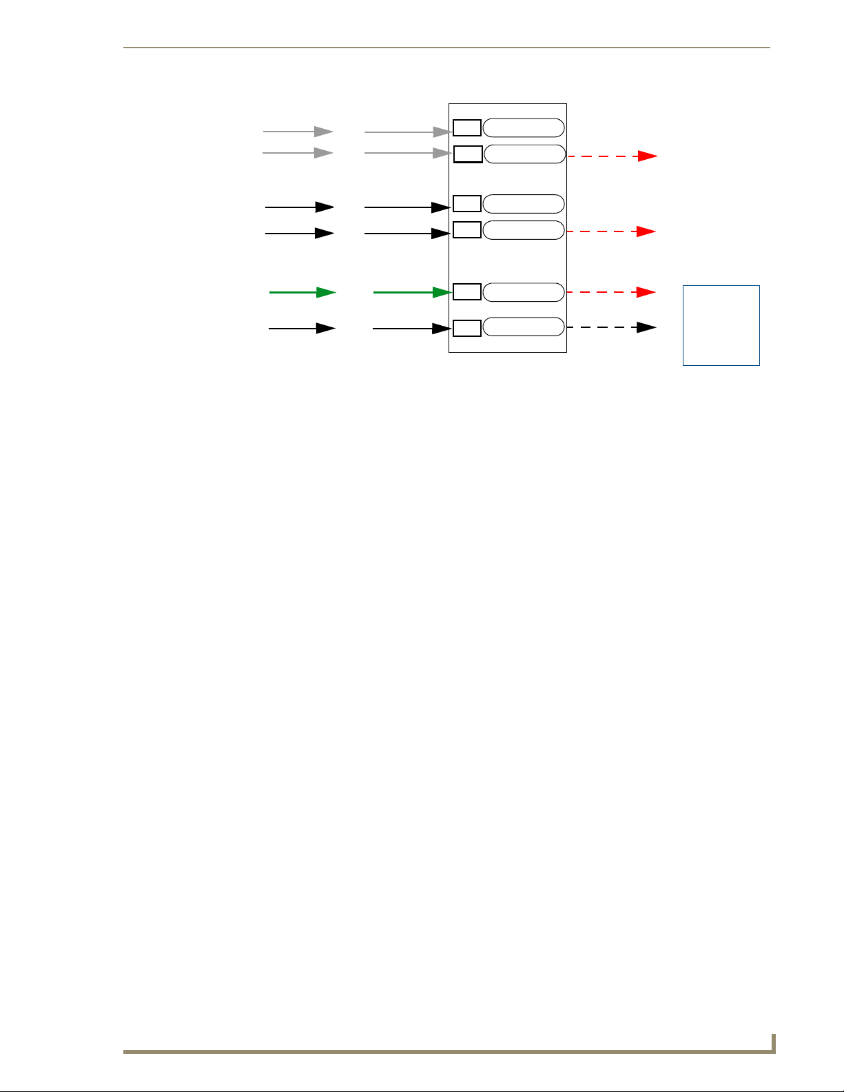
Tel net
SSH
Client
Web
Browser
Browser
or SSL
AMX
Software
&
Hardware
FTP
Telnet Access option
HTTP Access option
ICSP Connectivity
and Encryption option
443
1319
Telnet Port
23
22
HTTP Port
80
HTTPS Port
21
NetLinx Master
SSH Port
ICSP Por t
FTP Port
Secure
Secure
Secure
Secure
Username and
Password are
required when
enabled
FIG. 18 Port Communication Settings
Accepting Changes
Click the Accept button to save changes on this page. Accepting changes is instantaneous and does not
require a reboot.
System Level Security - IPSec Security Settings
Click the IPSec Security Settings link to access the IPSec Security Details page (FIG. 19). The options
in this page allow you configure IPSec-specific security options on the Master at the System level.
FIG. 19 IPSec Security Settings Page
NI Series WebConsole & Programming Guide
31
Page 40

WebConsole - Security Options
The IPSec Security Settings option is only available on the NI-700/900 and NI-X100
series.
Configuring Settings
1.
Check the Enabled option to enable Security, and make the following CRL Checking options
available (click the radio buttons to toggle on/off):
No CRL Checking: No CRL (Certificate Revocation List) checking will be done.
CRL Checking: Only the certificate in question will be checked against the CRL.
CRL Checking (All): Each certificate in an entire chain of certificates should be checked
2. Click the Update Settings button to save all changes to the Master.
Uploading an Configuration File
1.
Click the Browse button (next to the Upload Configuration File text box) to locate and select a
NetLinx compatible configuration file from your PC (or LAN).
The configuration file name can use any suffix, but it will be re-suffixed to *.cfg by the
Master.
against the CRL.
2. Click the Submit button to transfer the selected configuration file to the Master.
Managing Certificate Files
The Managing Certificate Files section of the page provides a display box that lists all of the existing
Certificate Files resident on the Master.
A certificate is a cryptographically signed object that associates a public key and an
identity. Certificates also include other information in extensions such as permissions
and comments
"CA" is short for "Certification Authority" - an trusted third party (or internal entity) that
issues, signs, revokes, and manages these digital certificates.
The display is separated into three tabs (click to view the selected type of Certificate Files):
Certificates: This tab displays all Identity certificates on the Master.
CA Certificates: This tab displays all Certificate Authority (CA) certificates on the Master.
CRL Certificates: This tab displays all Certificate Revocation List (CRL) certificates on the
Master.
To delete a Certificate from the Master, select a Certificate in any of the three tabs, and click Delete File.
AMX IPSec Configuration file
Refer to the Appendix A: IPSec Configuration File section on page 115 for a listing and description of
the configuration lines supported by the AMX IPSec Configuration file.
32
NI Series WebConsole & Programming Guide
Page 41

WebConsole - Security Options
System Security - Group Level
Select the Group Level tab of the Security Page to access the Group Security Details page (FIG. 20).
FIG. 20 Group Security Details page
The options in this page allow authorized users to assign and alter group properties such as creating,
modifying, or deleting a group’s rights, and also allows for the definition of the files/directories
accessible by a particular group.
A Group represents a logical collection of individual users. Any properties possessed
by a group are inherited by all members of that group.
Adding a New Group
Select the Group Level tab (in the Security section) to open the Group Security Details page.
1.
2. Click the Add New Group button (see FIG. 20) to access the Add a group and modify settings
page (FIG. 21).
3. In the Group Name field, enter a unique name for the new group.
The name must be a valid character string consisting of 4 - 20 alpha-numeric characters.
The string is case sensitive and must be unique.
The word "administrator" cannot be used for a new group name since it already exists by
default.
4. Enable the security access rights you want to provide to the group. By default, all of these options
are disabled. See the Group and User Security Access Options section on page 34 for details.
5. In the Group Directory Associations section, place a checkmark next to the directories (available
on the target Master) to provide an authorized group with access rights to the selected directories.
NI Series WebConsole & Programming Guide
33
Page 42

WebConsole - Security Options
FIG. 21 Group Level Security Settings Page (Add a group and modify settings page)
If you select a group directory, all lower groups in that tree will be selected.
6. Click the Accept button to save your changes to the target Master.
If there are no errors within any of the page parameters, a “Group added successfully” is displayed
at the top of the page.
Security changes made from within the web browser are applied instantly, without the
need to reboot.
Group and User Security Access Options
Group and User Security Access Options
Option Description
Admin Change Password
Access:
Terminal (RS232) Access: If selected, a valid username and password is required for Terminal communica-
HTTP Access: If selected, a valid username and password is required for communication over
This selection enables or disables the Administrator right to change Group and
User passwords.
tion via the Master’s RS232 Program port.
HTTP or HTTPS Ports, including accessing the WebConsole.
34
NI Series WebConsole & Programming Guide
Page 43

WebConsole - Security Options
Group and User Security Access Options (Cont.)
Option Description
Telnet Access: If selected, a valid username and password is required for Telnet Access. Telnet
access allows communication over either the Telnet and/or SSH Ports.
Note: SSH version 2 (only) is supported.
• To establish a secure Telnet connection, an administrator can decide to disable
the Telnet Port and then enable the SSH Port. Refer to the Manage System -
Server Options section on page 51.
Configuration: If selected, a valid username and password is required before allowing a group/
ICSP Connectivity: If selected, a valid username and password is required to communicate with the
Encrypt ICSP Connection: If selected, this option requires that any data being transmitted or received via an
user to alter the current Master’s security and communication settings via
NetLinx Studio.
This includes such things as: IP configuration/Reset, URL list settings, Master
communication settings, and security parameters.
NetLinx Master via an ICSP connection (TCP/IP, UDP/IP, and RS-232).
• This feature allows communication amongst various AMX hardware and
software components. This feature works in tandem with the Require
Encryption option (see below) to require that any application or hardware
communicating with the Master must provide a valid username and password.
• In a Master-to-Master system, the Master which accepts the IP connection
initiates the authentication process. This configuration provides compatibility
with existing implementations and provides more flexibility for the
implementation of other devices.
Note: The ICSP Connectivity option is required to allow authenticated and/or
secure communication between the Master and other AMX hardware/software.
To establish an authenticated ICSP connection (where the external AMX hardware/software has to provide a valid username and password), this option must
be enabled.
ICSP connection (among the various AMX products) be encrypted, and that any
application or hardware communicating with the Master over ICSP must provide
a valid username and password.
Note: When enabled, this option requires more processor cycles to maintain.
Telnet Access option
Tel net
SSH
Client
Web
Browser
Browser
or SSL
AMX
Software
&
Hardware
FTP
FIG. 22
HTTP Access option
ICSP Connectivity
and Encryption option
Port Communication Settings
NI Series WebConsole & Programming Guide
23
22
80
443
1319
21
NetLinx Master
Telnet Port
SSH Port
HTTP Port
HTTPS Port
ICSP Por t
FTP Port
Secure
Secure
Secure
Secure
Username and
Password are
required when
enabled
35
Page 44

WebConsole - Security Options
Viewing Group Security Settings Details
Click on any Group listed in the Group Security Details page to expand the view to show details for the
selected user Group (FIG. 23):
Click to add a new Group
FIG. 23 Group Security Details Page
Click the Edit button to edit the Security Access options for the selected user group.
Click Delete to delete the selected User Group from the Master.
Modifying the Properties of an Existing Group
Select the Group Level tab (in the Security section) to open the Group Security Details page.
1.
2. Click the Edit button to open the Group Security Details page for the selected group (FIG. 24).
3. Modify the previously configured access rights by enabling / disabling the checkboxes. See the
Group and User Security Access Options section on page 34 for details.
4. Modify the selected group’s directory access rights in the Group Directory Associations section, as
necessary (place / remove checkmarks next to the available directories).
5. Click the Accept button to save your changes to the Master.
If there are no errors with the modification of any of this page’s parameters, a “Group updated
successfully” is displayed at the top of the page.
36
NI Series WebConsole & Programming Guide
Page 45

WebConsole - Security Options
FIG. 24 Group Security Details Page (Edit Group Security Details)
The "administrator" group account cannot be modified or deleted.
Any properties possessed by groups (ex: access rights, update rights, directory associations, etc.) are
inherited by users assigned to that particular group.
Unchecking a security option (which is available within the associated group) does not remove that right
from the user. The only way to remove a group’s available security right from a target user is either to not
associate a group to a user or to alter the security rights of the group being associated.
Deleting a Group
Select the Group Level tab (in the Security section) to open the Group Security Details page.
1.
2. Press the Delete button to remove the selected group and refresh the page. The system will prompt
you to verify this action - click OK to proceed.
If you are not logged into the Master, you receive a reminder message: "You must login before
Security Settings can be changed". In this case, log into the Master and repeat the previous
steps.
If the group is associated with several users, you might get an error while trying to delete the
group. If this happens, change the group association of those specific users utilizing the old
group and either give them a new group or assign them (none) as a group. When you return to
delete the desired group, you receive a message saying "Group deleted successfully".
3. Click the Accept button to save your changes to the Master.
NI Series WebConsole & Programming Guide
37
Page 46

WebConsole - Security Options
System Security - User Level
Select the User Level tab of the Security Page to access the User Security Details page (FIG. 25). The
options on this page allow authorized users to add/delete User accounts and configure User’s Access
rights.
Click to add a new User
38
FIG. 25 User Security Settings Page
A User represents a single client of the Master, while a Group represents a collection of Users.
Any properties possessed by a Group are inherited by all of the Users in the group.
Adding a New User
Select the User Level tab (in the Security section) to open the User Security Details page.
1.
2. Click the Add New User button (see FIG. 25) to access the Add/Modify User page (FIG. 26).
3. In the User Name field, enter a unique name for the new group.
The name must be a unique alpha-numeric character string (4 - 20 characters), and is case
sensitive.
The words "administrator" and "NetLinx" cannot be used since they already exist by default.
4. In the Group drop-down list, choose from a list of pre-configured Groups and associate these rights
to the new user.
5. Enter a user password in both the Password and Password Confirm fields.
NI Series WebConsole & Programming Guide
Page 47

WebConsole - Security Options
FIG. 26 User Security Settings Page (Add/Modify User page)
The password must be a unique alpha-numeric character string (4 - 20 characters), and is case
sensitive.
6. Enable the security access rights you want to provide to the user. See the Group and User Security
Access Options section on page 34 for details.
7. In the Group Directory Associations section, place a checkmark next to the directories (available
on the target Master) to provide an authorized user with access rights to the selected directories.
This selection includes any sub-directories that exist within the selection.
8. Click the Accept button to save your changes to the Master.
Any security changes made to the Master from within the web browser are instantly
reflected within a Terminal session without the need to reboot.
Viewing and Editing User Security Settings
Click on any User listed in the User Security Details page to view and edit security settings for the
selected User (FIG. 27):
Click the Edit button to edit the Security Access options for the selected User.
Click Delete to delete the selected User from the Master.
Deleting a User
Select the User Level tab (in the Security section) to open the User Security Details page.
1.
2. Press the Delete button to remove the selected User and refresh the page. The system will prompt
you to verify this action - click OK to proceed.
NI Series WebConsole & Programming Guide
39
Page 48

WebConsole - Security Options
Click to edit Access settings for this User
Click to delete this User
FIG. 27 User Level Security Settings Page (Viewing User Security Settings Details)
If you are not logged into the Master, you receive a reminder message: "You must login before
Security Settings can be changed". In this case, log into the Master and repeat the previous steps.
3. Reboot the Master via the Reboot button on the Manage System Page (select the System control
button to access).
40
NI Series WebConsole & Programming Guide
Page 49

WebConsole - System Options
System Overview
The Manage System page is accessed by clicking on the System button. This page allows you to view
and configure various aspects of the NetLinx System, separated by four tabs:
Manage System - Options in this tab allow you to view/change the Master’s System Number,
Control/Emulate system devices, perform Diagnostics, configure Server settings and set the
time/date via the Clock Manager. See the System - Manage System section on page 41 for
details.
Manage License - Options in this tab allow you to add device licenses (Product ID and
License Key) to the Master. See the System - Manage License section on page 61 for details.
Manage NetLinx - Options in this tab allow you to view a detailed list of NetLinx devices
connected to the Master. See the System - Manage NetLinx section on page 63 for details.
Manage Devices - Options in this tab allow you to view the details of additional attached
devices (including module-supported third-party devices). See the System - Manage
Devices section on page 65 for details.
The default view for the System option is Manage System / System Number (FIG. 28).
WebConsole - System Options
These tabs provide access to the various
System Management features
(default view = Manage System)
FIG. 28 Manage System (System Number)
System - Manage System
The Manage System tab contains links to several different System-related configuration pages, as
described in the following subsections:
NI Series WebConsole & Programming Guide
41
Page 50

WebConsole - System Options
Manage System - System Number
The options on this page display the current System Number assigned to the target Master (read-only),
and allow you to change the system number (see FIG. 28).
Changing the System Number On the Master
Enter the new numeric value into the New System Number field.
1.
2. Click the Accept button to save this new value to the system on the target Master.
The message; "System number changed to X. Master must be rebooted for the change to take
effect.", reminds you that the Master must be rebooted before the new settings take effect.
3. Click Reboot to reboot the target Master.
The Device Tree then reads "Rebooting....". After a few seconds, the Device Tree refreshes
If the Device Tree does not refresh within a few minutes, press the Refresh button and
Using Multiple Netlinx Masters
When using more than one Master, each unit must be assigned to a separate System value.
A Master’s System value can be changed but it’s device Address must always be set to zero (00000).
The Device Addressing dialog will not allow you to alter the NetLinx Master address value.
Example: Using an NI-2000 and NI-4100:
The NI-2000 could be assigned to System 1 (with an Address of 00000).
The NI-4100 could be assigned to System 2 (with an Address of 00000).
with the current system information (including the updated system number assignment).
reconnect to the Master.
Manage System - Control/Emulate Options
Click the Control/Emulate link (in the Manage System tab) to access the Control/Emulate Options page
(FIG. 29). The options on this page allow you to Control or Emulate a device connected to this Master.
Device Control/Emulation is accomplished by manipulating a target device’s channels, levels, and
sending both send commands and strings to the device.
To Control a device means that the program generates messages which appear to a specified
device to have come from the Master.
To Emulate a device means that the program generates messages which appear to the Master
to have come from a specified device (physical or virtual). When Emulate is selected, a Push
button is added to the Channel Code section (see FIG. 29).
42
NI Series WebConsole & Programming Guide
Page 51

WebConsole - System Options
Push button only displayed if
Emulate is selected
FIG. 29 Manage System (Control/Emulate)
The System Number, Device Number, and Port Number fields are read-only. Instead
of specifying these values for a System Device, select a device via the Device Tree to
populate these fields with that device’s information.
Controlling or Emulating a System Device
Select the device that you want to Control or Emulate, via the Device Tree:
1.
a. Click the Show Device Tree option to show the Device Tree window (if it is not already
enabled).
b. In the Device Tree, click on the Information (i) icon for the device that you want to control or
emulate. This opens a Network Settings page showing network configuration details for the
selected device. See the Device Network Settings Pages section on page 23 for details.
c. Click on the Control/Emulate link. This opens a Control/Emulate Options page for the selected
device (FIG. 30).
2. Select either the Control or Emulate option.
3. In the Channel Code section, enter a valid Channel number to emulate Channel messages (i.e.,
Push/Release, CHON, and CHOFF) for the specified <D:P:S>.
The Channel number range is 1 - 65535.
NI Series WebConsole & Programming Guide
43
Page 52

WebConsole - System Options
Click on Control/Emulate from within
the device’s Network Settings page
to Control/Emulate that device
44
FIG. 30 Select Control/Emulate from within a selected Device’s Network Settings page
Select the On or Off buttons to Emulate Channel ON (CHON) and Channel OFF (CHOFF)
messages for the specified <D:P:S>.
4. Select the Push button to Emulate a push/release on the specified channel (not displayed if the
Control option is selected). Click and hold the Push button to observe how the device/Master
responds to the push message.
5. In the Level Code section, enter a valid Level number and Level data value for the specified
<D:P:S> and press the Send button to transmit the level data.
The Level number range is 1 - 65535.
The table below lists the valid Level data types and their ranges:
NI Series WebConsole & Programming Guide
Page 53

WebConsole - System Options
Level Data Type Minimum Value Maximum Value
CHAR 0 255
INTEGER 0 65535
SINTEGER -32768 32767
LONG 0 429497295
SLONG -2147483648 2147483647
FLOAT -3.402823466e+38 3.402823466e+38
6. In the Command and String fields, enter any character strings that can be sent as either a String or
Command, and press Send to transmit to the Master.
When entering a Send Command, do not include the "send c" or "send_command" in the
statement - only type what would normally occur within the quotes (but don't include the
quotes either).
For example to send the "CALIBRATE" send command, type CALIBRATE (no quotes)
rather than SEND_COMMAND <dev> "CALIBRATE".
String Expressions start and end with double quotes (" "). Double quotes are not escaped,
rather they are embedded within single quotes. String expressions may contain string literals,
decimal numbers, ASCII characters and hexadecimal numbers (prepended with a $), and are
comma-delimited.
String Literals start and end with single quotes ('). To escape a single quote, use three single
quotes (''').
NI Series WebConsole & Programming Guide
45
Page 54

WebConsole - System Options
Manage System - Diagnostics Options
Click the Diagnostics link (in the Manage System tab) to access the Diagnostics Options page (FIG. 31).
The options on this page allow authorized users to enable and monitor various diagnostic messages
coming from and going to System Devices.
46
Diagnostic Options table
FIG. 31 Diagnostics Options Page (with diagnostic messages enabled)
The System Number, Device Number, and Port Number value fields are read-only
(disabled). Instead of specifying these values for a System Device, select a device
via the Device Tree to populate these fields with that device’s values, as described
below.
Enabling Diagnostics On a Selected System Device
1.
Select the device that you want to Control or Emulate, via the Device Tree:
a. Click the Show Device Tree option to show the Device Tree window (if it is not already
enabled).
b. In the Device Tree, click on the Information (i) icon for the device for which you want to enable
or modify Diagnostics options. This opens a Network Settings page showing detailed
NI Series WebConsole & Programming Guide
Page 55
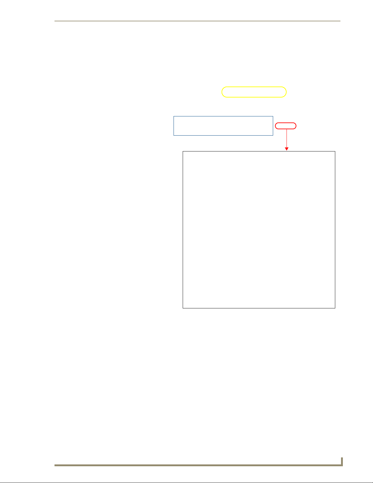
WebConsole - System Options
information on the selected device (including network configuration details). An example
Network Settings page is shown in FIG. 32:
c. Click on the Diagnostics link. This opens a Diagnostics Options page for the selected device
(FIG. 32).
Click on Diagnostics from within the device’s
Network Settings page to enable/modify
diagnostics for that device
FIG. 32 Select Diagnostics from within a selected Device’s Network Settings page
The currently selected device is also indicated in the Device field at the top of the
page.
2. By default, all diagnostics are disabled (see FIG. 32). To enable diagnostic messages from this
device, click on one of the Edit buttons along the bottom of the Diagnostics Options table.
This opens the Edit Options window (FIG. 33), where you can select which Diagnostics messages
to enable or disable for this device.
Once you have selected the diagnostics messages to enable, click Update to apply your changes,
close the Edit Options window, and return to the Diagnostics page.
Refer to the Diagnostics Options Definitions section on page 49 for definitions of each Diagnostic
option.
NI Series WebConsole & Programming Guide
47
Page 56

WebConsole - System Options
FIG. 33 Edit Options window
Click to delete this device from the Diagnostics page
(disables all diagnostics on this device)
Click to apply changes
Click to close the Edit Options window
(without disabling diagnostics)
Click to select from Presets
(saved sets of enabled Diagnostic messages)
Click to Store and Recall Presets
To set Diagnostic Options for a different System
Device, enter the device’s System, Device and Port
information in these fields (and press Update to
add the specified device/diagnostics options
to the Diagnostics page).
Click the checkboxes to enable/disable
specific diagnostic messages
Scroll down to see the entire list.
(All Notifications enables all messages)
3. The device that you just enabled diagnostics for appears in the Diagnostics Options page (identified
by its Number, Device and Port assignments at the top of the Diagnostics Option list), with the
currently enabled diagnostics indicated with a green checkmark (FIG. 34).
Each device is identified here by it’s System
Number, Device and Port assignments
Click to select a different Refresh Rate
(default = 5 seconds)
Click to modify the diagnostics settings
for this device, or to remove this device
from the Diagnostics Options list
FIG. 34 Edit Options window
48
All returned messages are displayed in the Incoming Messages window. By default, all messages
are refreshed every 5 seconds, as indicated by the Refresh Interval field. Use the Refresh Interval
drop-down to specify how often your messages are updated (available values = 2 seconds, 5
seconds, or 10 seconds). The default setting is 5 seconds.
4. To add more devices to the Diagnostics Options page:
NI Series WebConsole & Programming Guide
Page 57

WebConsole - System Options
Repeat steps 1-3.
Alternatively, you can click one of the Edit buttons to open the Edit Options window, and
specify a System Number, Device and Po rt for a known System Device. Select the Diagnostics
messages that you want to enable for this device and click Update.
The device will appear in the Diagnostics Options window, in the next available column (to
the right of the last device added - see FIG. 35).
FIG. 35 Edit Options window indicating four devices with Diagnostics enabled
You can monitor diagnostics for up to eight System Devices in this page.
Diagnostics Options Definitions
The following table describes each of diagnostics options that can be enabled via the Edit Options
window:
Diagnostic Options
Diagnostic Option Description
All Notifications: Enables every notification field.
System
• Number
•Device
•Port:
Messages
• Online/Offline Generates a message when there is a change in the target device’s online/offline
• Configuration Generates a message when there is a change in the target device’s configuration.
• Status Generates a message when there is a change in the target device’s status.
Use these fields to enter a device:port:system (D:P:S) combination for the device for
which you want to enable notifications.
A value of 0 for any option gives you all of the systems, devices, or ports. This dialog
also allows you to store/recall presets.
status.
NI Series WebConsole & Programming Guide
49
Page 58

WebConsole - System Options
Diagnostic Options (Cont.)
Diagnostic option Description
Channel Changes
• Input Generates a message when there is an input channel change (i.e. Push/Release) in
• Output Generates a message when there is an output channel change (i.e. CHON/CHOFF)
• Feedback Generates a message when there is a feedback channel change in the target
Device Options
• Level Changes From Generates a message when there is a level channel change from the target device.
• Level Changes To Generates a message when there is a level channel change to the target device.
• Strings To Generates a message when there is a string sent to the target device.
• Strings From Generates a message when there is a string from the target device.
• Commands To Generates a message when there is a command to the target device.
• Commands From Generates a message when there is a command from the target device.
• Custom Events From Generates a message there is a custom event occurring from the target device.
Disabling all Diagnostic Options For a Device
the target device.
in the target device.
device.
There are two ways to disable all diagnostics for a device:
In the Edit Options window, select Delete to remove the device from the Diagnostics Options
page and disable all diagnostics.
In the Edit Options window, deselect all selected diagnostics options and click Update. This
disables all diagnostics for this device, but leaves the device on the Diagnostics Options page.
Creating and Recalling Diagnostics Presets
The Store and Recall options in the Edit Options window allow you to save and recall preset diagnostics
configurations.
Presets are saved via cookies, so they do not persist across multiple browsers/
computers.
1. Click the Presets down arrow to open a list of previously stored Presets. By default, the only preset
is called 0: All Devices, All Notifications. This default Preset cannot be modified.
2. Select an empty Preset (for example 1:)
3. Select the desired diagnostic options, and click Store.
4. A popup window prompts you to name this Preset. Enter a name and click OK.
To recall an existing Preset, select it from the drop-down list and click on Recall.
A Preset MUST be Recalled before clicking the Update button. If you do not press
this button, none of the fields or checkboxes are modified or selected. In essence, all
options become disabled.
50
NI Series WebConsole & Programming Guide
Page 59

WebConsole - System Options
Manage System - Server Options
Click the Server link (in the Manage System tab) to access the Server Options page (FIG. 36). The
options on this page allow you to:
Change the port numbers (used by the Master for various Web services)
Configure the SSL settings used on the Master
Manage existing and pending license keys, manage the active NetLinx system communication
parameters
Configure/modify the SSL certificates on the target Master
FIG. 36 Server Options page
The options on this page are described below:
Port Settings
Allows a user to modify the server settings; specifically those port assignments associated with
individual services.
All items can be either enabled/disabled via the Enabled checkboxes.
The port number values (except the FTP port) can be modified in this page.
The default port for each service is listed to the right.
NI Series WebConsole & Programming Guide
51
Page 60

WebConsole - System Options
Server Port Settings
The following table describes each of the Port Settings presented on this page:
Server Port Settings
Feature Description
Tel net: The port value used for Telnet communication to the target Master. Enabling this feature allows
ICSP: The port value used for ICSP data communication among the different AMX software and hard-
HTTP: The port value used for unsecure HTTP Internet communication between the web browser’s UI
HTTPS/SSL: The port value used by web browser to securely communicate between the web server UI and
SSH: • The port value used for secure Telnet communication. A separate secure SSH Client would
future communication with the Master via a separate Telnet application (such as HyperTerminal).
• The default port value is 23.
• Refer to the NetLinx Security with a Terminal Connection section for more information on the
related procedures.
ware products. This type of communication is used by the various AMX product for communication amongst themselves. Some examples would be: NetLinx Studio communicating with a
Master (for firmware or file information updates) and TPDesign4 communicating with a touch
panel (for panel page and firmware updates).
• The default port value is 1319.
Note: To further ensure a secure connection within this type of communication, a user can
enable the Require Encryption option which requires additional processor cycles. Enabling of
the encryption feature is determined by the user.
and the target Master. By disabling this port, the administrator (or other authorized user) can
require that any consecutive sessions between the UI and the target Master are done over a
more secure HTTPS connection.
By default, the Master does not have security enabled and must be communicated with using
http:// in the Address field.
• The default port value is 80.
Note: One method of adding security to HTTP communication is to change the Port value. If the
port value is changed, any consecutive session to the target Master has to add the port value at
the end of the address (within the Address field). An example is if the port were changed to 99,
the new address information would be: http://192.192.192.192:99.
the target Master. This port is also used to simultaneously encrypt this data using the SSL certificate information on the Master as a key.
This port is used not only used to communicate securely between the browser (using the web
server UI) and the Master using HTTPS but also provide a port for use by the SSL encryption
key (embedded into the certificate). Whereas SSL creates a secure connection between a client
and a server, over which any amount of data can be sent securely, HTTPS is designed to transmit individual messages securely. Therefore both HTTPS and SSL can be seen as complementary and are configured to communicate over the same port on the Master. These two methods
of security and encryption are occurring simultaneously over this port as data is being transferred.
• The default port value is 443.
Note: Another method of adding security to HTTPS communication would be to change the port
value. If the port value is changed, any consecutive session to the target Master has to add the
port value at the end of the address (within the Address field). An example is if the port were
changed to 99, the new address information would be: http://192.192.192.192:99.
handle communication over this port. When using a secure SSH login, the entire login session
(including the transmission of passwords) is encrypted; therefore it is secure method of
preventing an external user from collecting passwords.
• SSH
version 2 is supported.
• The default port value is 22.
Note: If this port’s value is changed, make sure to use it within the Address field of the SSH Client application.
52
NI Series WebConsole & Programming Guide
Page 61

WebConsole - System Options
Server Port Settings (Cont.)
Feature Description
FTP: The default port value used for FTP communication.
This port can be disabled/enabled but the value can not be changed.
• The default port value is 21.
Once any of the server port settings have been modified, press the Accept button to save these changes to
the Master. Once these changes are saved, the following message appears: "Unit must be rebooted for the
change to take effect".
Click the Reboot button (from the top of the page) to remotely reboot the target Master. No dialog
appears while using this button. The Device Tree then reads "Rebooting....". After a few seconds, the
Device Tree refreshes with the current system information (indicating updated port numbers).
If the Device Tree contents do not refresh within a few minutes, press the browser’s
Refresh button and reconnect to the Master.
SSL Certificate Options
There are three SSL Certificate options, presented as links along the bottom of this page:
SSL Certificate Options
Create SSL Certificate: Opens the Create SSL Certificate window where you can create a self-
generated SSL certificate.
Note: A self-generated certificate has lower security than an external CA
(officially issued) generated certificate.
Export SSL Certificate Request: Takes the user to the Server Certificate page where they can view a previ-
ously created certificate.
An authorized user can also copy the raw text from a generated Certificate
request into their clipboard and then send it to the CA.
Import SSL Certificate: Takes the user to the Import Certificate page where they can import and
paste the raw text from a CA issued Certificate.
Creating an SSL Server Certificate
Initially, a NetLinx Master is not equipped with any installed certificates. In order to prepare a Master for
later use with "CA" (officially issued) server certificates, it is necessary to:
First create a self-generated certificate which is automatically installed onto the Master.
Secondly, enable the SSL feature from the Enable Security page. Enabling SSL security
after the certificate has been self-generated insures that the target Master is utilizing a secure
connection during the process of importing a CA server certificate over the web.
A certificate consists of two different Keys:
The Master Key is generated by the Master and is incorporated into the text string
sent to the CA during a certificate request. It is unique to a particular request made on
a specific Master. Note that regenerating a previously requested and installed
certificate invalidates that certificate because the Master Key has been changed.
The Public Key is part of the text string that is returned from the CA as part of an
approved SSL Server Certificate. This public key is based off the submitted Master
key from the original request.
NI Series WebConsole & Programming Guide
53
Page 62

WebConsole - System Options
1. Click the Create SSL Certificate link (under SSL Certificate Options) to access the Create SSL
Certificate window (FIG. 37).
FIG. 37 Create SSL Certificate window
2. Fill out the information in this window, according to the descriptions in the SSL Certificate Entries
section below.
3. Click Create SSL Certificate to update the Master with the information entered on this page. This
process can take several minutes.
SSL Certificate Entries
The following table describes the SSL Certificate entries presented in the Create SSL Certificate window
(FIG. 37):
SSL Certificate Entries
Entry Description
Bit Length: Provides a drop-down selection with three public key lengths (512, 1024, 2048).
• A longer key length results in more secure certificates.
• Longer key lengths result in increased certificate processing times.
Common Name: The Common Name of the certificate must match the URL Domain Name used for the
Master.
Example: If the address used is www.amxuser.com, that must be the Common name
and format used.
• The Common Name can not be an IP Address.
• If the server is internal, the Common Name must be Netbios.
• For every website using SSL that has a distinct DNS name, there must be a certificate
installed. Each website for SSL must also have a distinct IP Address.
• This domain name must be associated to a resolvable URL Address when creating a
request for a purchased certificate.
• The address does not need to be resolvable when obtaining a free certificate.
Action: Provides a drop-down selection with a listing of certificate actions:
• Display Certificate - Populates the Server Certificate fields with the information from
the certificate currently installed on the Master. This action is used only to display the
information contained in the certificate on the target Master.
• Create Request - Takes the information entered into these fields and formats the
certificate so it can be exported to the external Certificate Authority (CA) for later
receipt of an SSL Certificate.
This action is used to request a certificate from an external source.
• Self Generate Certificate - Takes the information entered into the previous fields and
generates its own SSL Certificate.
This action is used when no previous certificate has been installed on the target
Master, or a self-signed certificate is desired.
• Regenerate Certificate - Takes the information entered into the previous fields and
regenerates an SSL Certificate. This action changes the Master Key.
This method of certificate generation is used to modify or recreate a previously
existing certificate already on the Master.
54
NI Series WebConsole & Programming Guide
Page 63

WebConsole - System Options
SSL Certificate Entries (Cont.)
Entry Description
Organization Name: Name of your business or organization. This is an alpha-numeric string (1 - 50 charac-
ters in length).
Organization Unit: Name of the department using the certificate. This is an alpha-numeric string
(1 - 50 characters in length).
City/Location: Name of the city where the certificate is used. This is an alpha-numeric string
(1 - 50 characters in length).
State/Province: Name of the state or province where the certificate is used (alpha-numeric string, 1 - 50
characters in length).
Note: The state/province name must be fully spelled out.
Country Name: Provides a drop-down selection with a listing of currently selectable countries.
Displaying SSL Server Certificate Information
Click the Create SSL Certificate link in the Server Options page to open the Create SSL Certificate
window.
By default, the Display Certificate Action is selected and the fields in this window are
populated with information from the certificate installed on the Master.
If the Master does not have a previously installed certificate, these fields are blank.
Creating a Request for an SSL Certificate
1.
Click the Create SSL Certificate link in the Server Options page to open the Create SSL Certificate
window.
2. Fill out the fields, according to the descriptions in the SSL Certificate Entries section on page 54.
3. Click the down arrow next to the Action field, and choose Create Request from the drop-down list.
4. Click the Create SSL Certificate button to accept the information entered into the above fields and
generate a certificate file. Click Close to exit without making changes to the Master.
This refreshes the Server Certificate page, and if the certificate request was successful, displays a
"Certified request generated" message.
Self-Generating an SSL Certificate
Click the Create SSL Certificate link in the Server Options page to open the Create SSL Certificate
1.
window.
2. Fill out the fields, according to the descriptions in the SSL Certificate Entries section on page 54.
3. Click the down arrow next to Action and choose Self Generate Certificate.
When this request is submitted, the certificate is generated and installed into the Master in one step.
4. Click Create SSL Certificate to save the new encrypted certificate information to the Master. Click
Close to exit without making changes to the Master.
Regenerating an SSL Server Certificate Request
This action allows you to is used to modify or recreate a certificate already on the Master. For example,
if the company has moved from Dallas to Houston, all of the information is reentered exactly except for
the City.
1. Click the Create SSL Certificate link in the Server Options page to open the Create SSL
Certificate window.
2. Modify the certificate information as needed (see the SSL Certificate Entries section on page 54).
3. Click the down arrow next to Action and choose Regenerate Certificate.
NI Series WebConsole & Programming Guide
55
Page 64

WebConsole - System Options
4. Click Create SSL Certificate to save the newly modified certificate information to the Master.
Click Close to exit without making changes to the Master.
Only use the Regenerate Certificate option when you have self-generated your own
certificate. Do not regenerate an external CA-generated certificate.
Exporting an SSL Certificate Request
1.
First follow the procedures outlined in the Creating a Request for an SSL Certificate section on
page 55 to create a session-specific Master certificate.
2. Click the Export SSL Certificate link to display the certificate text file in the Export SSL
Certificate window (FIG. 38).
FIG. 38 Export SSL Certificate window
3. Place your cursor within the certificate text field. The certificate text begins with the line that reads
"-----BEGIN CERTIFICATE REQUEST-----" (scroll down to view the certificate text.)
4. Select all (Ctrl + A) of the certificate text.
You must copy all of the text within this field, including the -----BEGIN CERTIFICATE
REQUEST----- and the -----END CERTIFICATE REQUEST----- portions. Without this text
included in the CA submission, you will not receive a CA-approved certificate.
5. Copy (Ctrl + C) the text to the clipboard.
6. Paste (Ctrl + V) this text into the Submit Request field on the CA’s Retrieve Certificate web page.
7. Choose to view the certificate response in raw DER format.
Note the Authorization Code and Reference Number (for use in the e-mail submission of the
request).
8. Submit the request.
9. Paste the copied text into your e-mail document and send it to the CA with its accompanying
certificate application.
When a certificate request is generated, you are creating a private key on the Master.
You can not request another certificate until the previous request has been fulfilled.
Doing so voids any information received from the previously requested certificate and
it becomes nonfunctional if you try to use it.
56
Once you have received the returned CA certificate, follow the procedures outlined in the following
section to import the returned certificate (over a secure connection) to the target Master.
NI Series WebConsole & Programming Guide
Page 65

WebConsole - System Options
Importing an SSL Certificate
Click the Import SSL Certificate link to import a CA server certificate. Before importing an SSL
Certificate you must:
First, have a self-generated certificate installed onto your target Master.
Second, enable the HTTPS/SSL feature from the Server Options page (FIG. 36), to establish a
secure connection to the Master prior to importing the encrypted CA certificate.
1. Copy the returned certificate (signed by the CA) to your clipboard.
2. Click the Import SSL Certificate link to open the Import SSL Certificate window (FIG. 39).
FIG. 39 Import SSL Certificate window
3. Place the cursor inside the text box and paste the returned certificate text, in its entirety.
4. Click Import SSL Certificate to save the new certificate information to the Master.
Once a certificate has been received from an external CA and installed on a Master,
do not regenerate the certificate or alter its properties. Regenerating a previously
installed certificate, invalidates the certificate.
5. Click the Display Certificate link to confirm the new certificate was imported properly to the target
Master.
A CA certificate can only be imported to a target Master only after both a selfgenerated certificate has been created and the SSL Enable feature has been
selected on the Master. These actions configure the Master the secure
communication necessary during the importing of the CA certificate.
NI Series WebConsole & Programming Guide
57
Page 66

WebConsole - System Options
Manage System - Clock Manager Options
Click the Clock Manager link (in the Manage System tab) to access the Clock Manager Options page
(FIG. 40). The options on this page allow you to enable/disable using a network time source and provide
access to Daylight Saving configuration and which NIST servers to use as a reference.
Date and Time are only available
if Stand Alone is selected as the
Time Synch option.
FIG. 40 Clock Manager Options - Mode Settings tab
The Clock Manager Options are separated into three tabs:
Mode Settings - The Mode Manager in this tab allows you to set the Clock Manager Mode
(Network Time or Stand Alone).
Daylight Savings - The Daylight Savings Manager in this tab allows you to specify how and
when to implement Daylight Savings rules on the clock.
NIST Servers - The NIST Server Manager in this tab allows you to connect to a specific
NIST (Internet Time Service) Server.
Setting the Mode for the Clock Manager
In the Mode Settings tab (FIG. 40), select a Time Synch option.
1.
Network Time: This option allows the Master to manage it’s clock by connecting to a NIST
(Internet Time Service) Server. When this option is selected, the Master will connect to the
default NIST Server to get date and time information.
You can select a different NIST Server (or specify the IP Address of a known NIST Server) in
the NIST Servers tab (see the Selecting a Custom NIST Server section on page 60).
Stand Alone: This option lets the Master use its own internal clock. When this option is
selected, two additional fields are available on this tab:
Date - Enter the current date in these fields (mm/dd/yyyy).
Time - Enter the current time in these fields (hh/mm/ss).
58
NI Series WebConsole & Programming Guide
Page 67

WebConsole - System Options
2. Click Accept to save these settings to the Master.
Setting Daylight Savings Rules
1.
In the Daylight Savings tab (FIG. 41), enable Daylight Savings mode by clicking the On button.
FIG. 41 Clock Manager Options - Daylight Savings tab
2. Use the Offset drop-down menus to adjust the amount of time (hours and minutes) to offset
Daylight Savings. By default, the offset is set to 1 hour.
Although most places that support Daylight Savings usually adjust the local time by
one hour this doesn't cover all locations. To provide flexibility for such locations it is
possible to configure a different daylight savings time offset.
3. Use the Starts fields to specify when Daylight Savings should start. The Starts rules include:
Select Fixed to specify the calendar date when the rule applies as a specific date ("March 21").
When Fixed is selected, use the Day, Month and Starts fields to specify the date and time
(hh:mm) to start Daylight Savings time.
Select by Occurrence to specify the calendar date when the rule applies as a heuristic,
("the 3rd Sunday in March").
When by Occurrence is selected, use the Week of the Month,
Day of the Week, Month and Starts fields to specify the occurrence to start Daylight Savings
time.
The range is 1 through Last, where Last indicates the last occurrence of a particular day of the
month. This is to accommodate months that include four weeks as well as those that include
five.
NI Series WebConsole & Programming Guide
59
Page 68

WebConsole - System Options
4. Use the Ends fields to specify when Daylight Savings should end. The Ends rules match the Start
rules, and follow the same logic. Select Fixed or by Occurrence, and specify the End date/time
information accordingly.
5. Click Accept to save these settings to the Master.
Selecting a Custom NIST Server
FIG. 42 Clock Manager Options - NIST Servers tab
In the NIST Servers tab (FIG. 42), use the radio buttons to select one of the NIST Servers in the list.
1.
2. Click Accept to save these settings to the Master.
Adding a Custom NIST Server To the List
Click on the radio button next to the last (blank) entry in the NIST Server Manager list.
1.
2. In the URL field, enter the URL of the NIST Server. The URL is used only to help you manage
entries, and is not verified or used internally by the clock manager.
3. Enter the NIST Server’s IP Address in the IP field. This is used internally and must be a valid IP
address.
The strings entered into the URL and Location fields are not used to connect to NIST
Servers. The IP Address (entered into the IP field) specifies the NIST Server(s) that
will be used. As stated above, the address entered into the IP field must be must be a
valid IP address (not a URL).
4. Enter the NIST Server’s location in the Location field. This is used only to help the user manage
entries and it is not verified or used internally by the clock manager.
5. Click Accept to save these settings to the Master.
60
NI Series WebConsole & Programming Guide
Page 69

WebConsole - System Options
Removing an NIST Server From the List
1.
Click on the Remove (x) button to the right of a user-added NIST Server in the NIST Server
Manager list.
2. Click Accept to save these settings to the Master.
The built-in entries cannot be removed.
Clock Manager NetLinx Programming API
Refer to Appendix B: Clock Manager NetLinx Programming API section on page 141 for a listing and
description of the Types/Constants and Library Calls that are included in the NetLinx.AXI to support
Clock Manager functions.
System - Manage License
The Manage License tab displays current as well as pending license keys (FIG. 43).
FIG. 43 System - Manage License tab (with one example entry)
The Add New License button allows for the addition of new license keys associated with currently used
modules/products. Adding new License Keys requires the entry of both a Product ID and a Serial Key
(example: i!-Voting).
The Master confirms this registration information before running the module or product.
Adding A New License
1.
Click the Add New License button to access the Add a License page (FIG. 44).
2. Enter the Product ID (certificate number) provided with the product into the Product ID fields.
Contact the AMX Sales department with both the product serial number (or certificate number) and
the serial number of target Master to register your product and in turn receive the necessary Key
information (typically 32 to 36 digits in length) which is then entered into the Key fields on this
page.
3. Enter the Product Key into the Key fields. The Product Key is Master-specific and is typically
provided by AMX upon registration.
NI Series WebConsole & Programming Guide
61
Page 70

WebConsole - System Options
FIG. 44 Manage License - Add a License page
Example: AMX Meeting Manager and i!-Voting applications are examples of products that require
both a Product serial number and a Master-specific key prior to usage.
4. Press the Accept button to save the information. If there are no errors with the information on this
page, a “Key successfully added for Product ID XXXX” is displayed at the top of the page.
Removing a License
1.
Click the Remove (x) icon to the left of the license that you want to remove.
2. The system will prompt you to verify this action before the license is removed from the Master.
Click OK to proceed.
3. Press the Accept button to save the information.
62
NI Series WebConsole & Programming Guide
Page 71

WebConsole - System Options
System - Manage NetLinx
The Manage NetLinx tab displays a list of NetLinx device connected to the Master, and indicates device
status (FIG. 45).
FIG. 45 System - Manage NetLinx tab
The table on this page consists of five columns:
NetLinx Device Details
Column Description
System: Displays the System value being used by the listed NetLinx Master.
Device: • Displays the assigned device value of the listed unit. This Device entry applies to both the
Master and those NDP-capable devices currently connected to that Master.
Device Type: • Displays a description of the target Master or connected device, and its current firmware
version. Example: NI Master v3.01.323.
File Name: Displays the program name and/or file resident on the device.
NI Series WebConsole & Programming Guide
63
Page 72

WebConsole - System Options
NetLinx Device Details (Cont.)
Column Description
Status: Indicates the Master or device state:
Refresh List: Click this button to regenerate the device listing by looking for broadcasting
• This Master: Indicates its the target Master currently being used and being browsed to. Its
this Master’s web pages which are currently being viewed.
• Orphan: Indicates that the device is currently not yet “bound” or assigned to communicate
with a particular Master. This state shows an adjacent Bind button which is used to bind the
device to the Master whose web pages are currently being viewed.
• Searching: Indicates that the device is trying to establish communication with it's
associated Master.
• Bound: Indicates that the device has established communication with it's associated
Master. This state shows an adjacent Unbind button which is used to release/disassociate
the device from communicating with its current Master.
• Lost: Indicates that the device has tried to establish communication with it's associated or
“bound” Master, but was after a period of time, unable to establish communication.
devices. This causes the Master to send out a message asking devices to resend their NDP
device announcements. The list is then updated as those devices send back their
announcements to the Master.
The information displayed can not only include Masters and devices on this system but
Masters and devices on other systems as well. By default, the target Master always appears in
the list.
Due to system delays, message collisions, and multicast routing, not all devices may
respond immediately.
Clear List: Click this button causes the entries to be temporarily deleted from the page, either
until you refresh the list (using the Refresh List button), or until the Master begins to detect
any multi-cast transmissions from System Devices.
64
NI Series WebConsole & Programming Guide
Page 73

WebConsole - System Options
System - Manage Devices
The Manage Devices tab (FIG. 46) contains links to several different device-related pages, as described
in the following subsections:
FIG. 46 System - Manage Devices (Details for Additional Devices)
Manage Devices - Device Options
Click the Device Options link (in the Manage Devices tab) to access the Details for Additional Devices
page (FIG. 46). The options on this page display various details specific to additional (non-NetLinx)
System Devices.
Configuring Device Binding Options
1.
Use the Configure Binding Options options to specify how the Master will manage Bound
Devices:
Binding Options
Option Description
Enable Auto Bind: This selection allows you to toggle the state of the automatic binding for
DDD (On/Off).
When auto-binding is enabled, the Master automatically attempts to connect any newly discovered device with an associated application device
(defined in the running NetLinx application).
Auto-binding can only be accomplished if the Master's firmware determines a one-to-one correlation between the newly discovered device and
a single entry within the list of defined application devices (accessed via
the Binding link at the top of this page).
NI Series WebConsole & Programming Guide
65
Page 74

WebConsole - System Options
Binding Options (Cont.)
Option Description
Enable Auto Bind (Cont.): For example, if the application only has one VCR defined and a VCR is
Enable Auto-Shutdown: Auto-Shutdown forces the termination of modules that have lost commu-
Enable Subnet Match: This selection allows you to specify whether or not IP devices should only
Purge Bound Modules on Reset: This selection indicates that all modules should be deleted from the bound
Disable Module Search
via Internet:
detected in the system, auto-binding can then be accomplished. If there
were two VCRs defined within the application, auto-binding could not be
completed due to the lack of a clearly defined one-to-one correspondence.
When this option is not selected, no auto-binding activity takes place and
all binding of the newly discovered devices must be accomplished manually via the Web control interface.
nication with their respective physical device. This capability is needed for
plug-and-play support.
By default, Auto-Shutdown is enabled. If automatic termination of modules when they have lost communication is not desired, this selection
should be disabled.
be detected/discovered if they are on the same IP Subnet as the Master.
directory upon the next reboot.
During the binding process, the associated Duet modules for a device are
copied from the /unbound directory into a protected /bound area.
Due to the dynamic nature of Java class loading, it is not safe to delete a
running .JAR file. Therefore, this selection provides the administrator the
capability of removing existing modules upon reboot by forcing a re-acquisition of the module at bind time.
This selection is a one-time occurrence - upon the next reboot, the selection is cleared.
This option toggles the capability of searching the Internet (either AMX's
site or a device specified site) for a device’s compatible Duet modules.
This capability is automatically disabled if the Master does not have Internet connectivity.
Upon enabling Internet connectivity, the AMX License Agreement is displayed. The License Agreement must be accepted for Internet Module
search feature to be enabled.
When this feature is enabled, the Master queries either AMX's Online
database of device Modules and/or pulls Modules from a separate site
specified by the manufacturer's device.
You can later disable this feature by toggling this button.
66
2. Press the Accept button to save your changes.
Managing Device Modules
Use the Manage Device Modules set of options to archive or delete modules from the Master. All
modules currently present on the Master are indicated in the Module list.
To archive a module:
1. Select a module and click the Archive Module button.
2. This action copies the selected module (*.JAR) file to your PC.
3. The system will prompt you to specify a target directory to save the module file to.
To delete a module:
Select a module and click the Delete Module button. This action deletes the selected module from the /
unbound directory.
NI Series WebConsole & Programming Guide
Page 75

WebConsole - System Options
Any corresponding module within the /bound directory will not be deleted. Bound
modules must be deleted via the Purge Bound Modules on Reset selection described
within the Configure Device Bindings section.
To browse for a Module file and then upload it to the Master:
1. Click the Browse button next to the Select a module to upload text field to browse for Duet
Modules on your PC/Network.
2. Select the JAR file that you want to upload to the Master.
3. Click the Submit button to upload a copy of the selected JAR file to the target Master's /unbound
directory.
If a file of the same specified name already exists within the /unbound directory, the system
will prompt you to confirm overwriting the existing file.
Only JAR file types are allowed for Upload to the target Master.
Manage Devices - Bindings
Click the Bindings link (in the Manage Devices tab) to access the Manage Device Bindings page
(FIG. 47). Use the options on this page to configure application-defined Duet virtual devices with
discovered physical devices.
FIG. 47 System - Manage Devices (Manage Device Bindings)
The table on this page displays a list of all application-defined devices, including each device’s "Friendly
Name", the Duet virtual device’s D:P:S assignment, the associated Duet Device SDK class (indicating
the type of the device), and the physical device’s D:P:S assignment. This information has to be pre-coded
into the NetLinx file currently on the Master.
NI Series WebConsole & Programming Guide
67
Page 76

WebConsole - System Options
Configuring Application-Defined Devices
Elements such as DUET_DEV_TYPE_DISC_DEVICE and DUET_DEV_POLLED are defined within the
NetLinx.axi file.
The NetLinx.axi file contains both the new API definitions, as well as the pre-defined constants that are
used as some of the API arguments (ex:
Physical device names are typically prefixed with "dv" and Virtual device names are
typically prefixed with "vdv".
Example Code:
PROGRAM_NAME='DDD'
DEFINE_DEVICE
COM1 = 5001:1:0
COM2 = 5001:2:0
dvRECEIVER1 = 41000:1:0
dvDiscDevice = 41001:1:0
DEFINE_CONSTANT
DEFINE_TYPE
DEFINE_VARIABLE
DUET_DEV_TYPE_DISC_DEVICE).
DEFINE_START
STATIC_PORT_BINDING(dvDiscDevice, COM1, DUET_DEV_TYPE_DISC_DEVICE,
'My DVD', DUET_DEV_POLLED)
DYNAMIC_POLLED_PORT(COM2)
DYNAMIC_APPLICATION_DEVICE(dvRECEIVER1, DUET_DEV_TYPE_RECEIVER,
'My Receiver')
(***********************************************************)
(* THE EVENTS GO BELOW *)
(***********************************************************)
DEFINE_EVENT
DATA_EVENT [dvRECEIVER1]
{
// Duet Virtual device data events go here
}
Sample code can be found within the DEFINE_START section, as shown in FIG. 48:
68
NI Series WebConsole & Programming Guide
Page 77

WebConsole - System Options
FIG. 48 Manage Device Bindings page - showing the NetLinx code relation
This code gives the Master a “heads-up” notification to look for those devices meeting the criteria
outlined within the code.
Application Devices and Association Status
There are two types of application devices: Static Bound application devices and Dynamic application
devices:
Static Bound application devices specify both a Duet virtual device and its associated Device
SDK class type, as well as a NetLinx physical device port to which the application device is
always associated (i.e. statically bound).
Dynamic application devices specify both the Duet virtual device and its associated Device
SDK with no association to a physical port. Binding of an application device to a physical
device/port occurs at run-time (either via auto-binding or manual binding).
Application devices that have a "bound" physical device display their physical device ID within the
Physical Device column. If an associated Duet module has been started to communicate with the device,
its associated property information is displayed in a mouse-over popup dialog when the cursor hovers
over the physical device ID (see FIG. 49 on page 71).
NI Series WebConsole & Programming Guide
69
Page 78

WebConsole - System Options
Each entry in the table has one of four buttons to the right of the Physical Device D:P:S assignment:
Static Bound application devices will either be blank, or display a Release button:
Dynamic application devices either display a Bind or Unbind button:
If a currently bound device needs to be replaced or a Duet Module needs to be
swapped out, the device should be unbound and the new module/driver should then
be bound.
Static Bound application devices that have not yet detected a physical device attached to
their associated port have a blank button.
Once a physical device is detected and its associated Duet module has been started, a
Release button is then displayed. Click Release to force the associated Duet module to
be destroyed and the firmware then returns to detecting any physical devices attached to
the port.
Dynamic application devices that have been bound display an Unbind button. When the
user selects Unbind, any associated Duet module is then destroyed and the "link"
between the application device and the physical device is then broken.
Dynamic application devices that have not been bound to a physical device display a
Bind button. When this button is selected, a secondary display appears with a listing of
all available unbound physical devices that match the application device's Device SDK
class type.
The administrator/user can then select one of the available physical devices to bind with the associated
application device. When the Save button is selected, the binding is created and a process begins within
the target Master to find the appropriate Duet Module driver. Once a driver is found, the Duet Module is
then started and associated with the specified application device (Duet virtual device). If the Cancel
button is selected, the binding activity is then aborted.
If the manufacturer device does not support Dynamic Device Discovery (DDD)
beaconing, you must use the Add New Device page to both create and manage
those values necessary to add a dynamic physical device. This process is described
in detail within the following section.
Viewing Physical Device Properties
Hold the mouse cursor over the Physical Device - Device entry in the table to display detailed device
properties for that device, in a pop-up window (FIG. 49).
70
NI Series WebConsole & Programming Guide
Page 79

WebConsole - System Options
Hold the mouse cursor over the
Device D:P:S assignment to open
the Device Properties pop-up
FIG. 49 Manage Device Bindings - Device Properties pop-up
Manage Devices - User-Defined Devices
Click the User-Defined Devices link (in the Manage Devices tab) to access the User-Defined Devices
page (FIG. 50). This page provides a listing with all of the dynamic devices that have been discovered in
the system, and allows you to add and delete User-Defined Devices.
FIG. 50 System - Manage Devices (User-Defined Devices)
Adding a User-Defined Device
1.
Click the Add Device button (in the User-Defined Devices page) to access the Add User Defined
Device page (FIG. 51):
NI Series WebConsole & Programming Guide
71
Page 80

WebConsole - System Options
FIG. 51 User-Defined Devices - Add User Defined Device
2. Fill in the device information fields, as described in the following table:
User-Defined Device Information Fields
Address: Enter the address of the physical device in the Address field.
This information can be either the NetLinx Master port value (D:P:S) or an IP Address (#.#.#.#).
Category: Use the drop-down list to select the control method associated with the physical target device
SDK Class: Use the drop-down list to select the closest Device SDK class type match for the physical target
GUID: Enter the manufacturer-specified device’s GUID (Global Unique Identification) information.
Make: Enter the name of the manufacturer for the device being used (ex: Sony, ONKYO, etc.)
Model: Enter the model number of the device being used (ex: Mega-Tuner 1000)
Revision Enter the firmware version used by the target device.
(IR, IP, Serial, Relay, Other).
device. The SDK-Class Types table (below) provides a listing of the available choices.
Either the GUID or Make/Model must be specified in this field.
• Up to 55 alpha-numeric characters
• Either the GUID or Make/Model must be specified within this field.
• Spaces in the name will be converted to underscores.
• Up to 255 alpha-numeric characters
• Either the GUID or Make/Model must be specified within this field.
• Text is required within this field.
• The version must be in the format: major.minor.micro (where major, minor, and micro are
numbers). An example is: 1.0.0 (revision 1.0.0 of the device firmware).
72
NI Series WebConsole & Programming Guide
Page 81

WebConsole - System Options
SDK-Class Types
Amplifier HVAC SlideProjector
AudioConferencer IODevice Switcher
AudioMixer Keypad Text Keypad
AudioProcessor Light TV
AudioTape Monitor UPS
AudioTunerDevice Motor Utility
Camera MultiWindow VCR
Digital Media Decoder PoolSpa VideoConferencer
Digital Media Encoder PreAmpSurroundSoundProcessor VideoProcessor
Digital Media Server RelayDevice VideoProjector
Digital Satellite System Receiver VideoWall
Digital Video Recorder Security System VolumeController
Disc Device Sensor Device Weather
DocumentCamera SettopBox
3. Once you are done creating the profile for the new device, click the Add Property button to access
the Name and Va lu e fields property information for association with the new User Defined Device.
4. Click the Accept button. The new device is indicated in the list of discovered physical devices (in
the User-Defined Devices page).
Manage Devices - View All Active Devices
Click the Active Devices link (in the Manage Devices tab) to access the View All Active Devices page
(FIG. 52). The options on this page allow you to check devices for compatible Duet Modules.
FIG. 52
Searching For All Compatible Duet Modules for a Selected Device
System - Manage Devices (User-Defined Devices)
Click the Search button for the device that you want to find a Duet Module for. This action initiates
1.
a search for compatible modules, based on the following options:
NI Series WebConsole & Programming Guide
73
Page 82

WebConsole - System Options
Unless the Disable Module Search via the Internet option was selected in the Manage
If the device specified a URL in its DDD beacon, the file is retrieved from the URL either over
If Module Search via Internet is NOT enabled, the search does NOT query the AMX online
Modules that are retrieved from either the Internet or from the manufacturer's device are then placed
into the /unbound directory and automatically overwrite any existing module of the same name.
2. Once a list of all compatible modules is compiled, the Available Modules list is displayed on this
page.
Each module is listed with its calculated “match” value. The greater the “match” value, the better
the match between the Duet Module's properties and the physical device's properties.
3. Select a module and click the Accept button to associate the selected Duet module with the physical
device.
Devices page (see the Manage Devices - Device Options section on page 65), the search
includes a query of the AMX online database as well as any manufacturer specified URLs that
match the IP Address of the physical device for a compatible module.
the Internet or from the physical device itself, provided the device has an inboard HTTP or
FTP server.
database nor will it pull any manufacturer specified URLs that do not match the IP Address of
the physical device itself.
This action will not affect any currently running Duet module associated with the
physical device. The module is associated with the device upon reboot.
Viewing Physical Device Properties
Hold the mouse cursor over the Device entry in the table to display detailed device properties for that
device, in a pop-up window (FIG. 53).
Hold the mouse cursor over the
Physical Device IP Address to open
the Device Properties pop-up
74
FIG. 53 View All Active Devices - Device Properties pop-up
NI Series WebConsole & Programming Guide
Page 83

WebConsole - System Options
Manage Devices - Manage Polled Ports
Click the Polled Ports link (in the Manage Devices tab) to access the Manage Polled Ports page
(FIG. 54). The options on this page allow you to view/modify settings for all polled ports in the System.
Click to open the Edit Port Settings page
FIG. 54 System - Manage Devices (Manage Polled Ports)
Polled Ports must be specified in the Master’s code in order for this page to be
populated.
Editing Polled Port Settings
Click the Edit button for a port in the Physical Port list to access the Edit Port Settings page (FIG. 55):
NI Series WebConsole & Programming Guide
75
Page 84

WebConsole - System Options
FIG. 55 Manage Polled Ports - Edit Port Settings
Use the drop-down menus to modify the Port settings.
Click Reset to Default Settings to return this port to its default configuration:
Default Port Settings
Baud Rate: 9600
Data Bits: 8
Parity: None
Stop Bits: 1
Flow Control None
485: Disabled
76
NI Series WebConsole & Programming Guide
Page 85

Programming
Overview
This section describes the Send_Commands, Send_Strings, and Channel commands you can use to
program the Integrated Controller. The examples in this section require a declaration in the
DEFINE_DEVICE section of your program to work correctly. Refer to the NetLinx Programming
Language instruction manual for specifics about declarations and DEFINE_DEVICE information.
Master Send_Commands
These commands are specific to the Master and not the Controller. These commands are sent to the DPS
0:1:0 (the Master you are connected to).
A device (<DEV>) must first be defined in the NetLinx programming language with values for the
Device: Port: System (<D:P:S>).
Master Send_Commands
Command Description
CLOCK
Set the date and time on the
Master.
G4WC
Add G4WebControl devices
to Web control list displayed
by the Web server in a
browser.
Programming
The date and time settings are propagated over the local bus.
Syntax:
SEND_COMMAND <DEV>,"'CLOCK <mm-dd-yyyy> <hh:mm:ss>'"
Variables:
mm-dd-yyyy = Month, day, and year. Month and day have 2 significant digits.
Year has 4 significant digits.
hh-mm-ss = Hour, minute, and seconds. Each using only 2 significant digits.
Example:
SEND_COMMAND 0,"'CLOCK 04-12-2005 09:45:31'"
Sets the Master's date to April 12, 2005 with a time of 9:45 am.
The internal G4WC Send command (to Master 0:1:0) has been revised to add
G4WebControl devices to Web control list displayed in the browser.
Syntax:
SEND_COMMAND <D:P:S>,"'G4WC "Name/Description",IP
Address/URL,IP Port,Enabled'"
Variables:
• Name/Description = A string, enclosed in double quotes, that is the
description of the G4 Web Control instance. It is displayed in the browser.
• IP Address/URL = A string containing the IP Address of the G4 Web Control
server, or a URL to the G4 Web Control server.
• IP Port = A string containing the IP Port of the G4 Web Control Server.
• Enabled = 1 or 0. If it is a 1 then the link is displayed. If it is a 0 then the link is
disabled.
The combination of Name/Description, IP Address/URL, and IP Port are used
to determine each unique listing.
Example:
SEND_COMMAND 0:1:0,"'G4WC "Bedroom",192.168.1.2,5900,1'"
Adds the BEDROOM control device using the IP Address of 192.168.1.2.
NI Series WebConsole & Programming Guide
77
Page 86

Programming
Master Send_Commands (Cont.)
Command Description
~IGNOREEXTERNALCLOCKCOMMANDS
Set the Master so that it
cannot have it’s time set by
another device which
generates a ‘CLOCK’
command.
Syntax:
SEND_COMMAND <D:P:S>,"'~IGNOREEXTERNALCLOCKCOMMANDS'"
Example:
SEND_COMMAND 0:1:0,"'~IGNOREEXTERNALCLOCKCOMMANDS'"
Master IP Local Port Send_Commands
These commands are specific to the Master and not the Controller. These commands are sent to the DPS
0:1:0 (the Master). A device must first be defined in the NetLinx programming language with values for
the Device: Port: System.
In these programming examples, <DEV> = Device. The term <D:P:S> = Device:Port:System.
Master IP Local Port Send_Commands
Command Description
UDPSENDTO
Set the IP and port number of
the UDP local ports
destination for sending future
packets.
This is only available for Type 2 and Type 3 Local Ports. Type 2 and Type 3 are
referring to the protocol type that is part of the IP_CLIENT_OPEN call
(4th parameter).
Type 1 is TCP.
Type 2 is UDP (standard)
Type 3 is UDP (2 way)
The NetLinx.axi defines constants for the protocol types:
CHAR IP_TCP = 1
CHAR IP_UDP = 2
CHAR IP_UDP_2WAY = 3
Syntax:
SEND_COMMAND <D:P:S>,"'UDPSENDTO-<IP or URL>:<UDP Port
Number>'"
Variables:
• IP or URL = A string containing the IP Address or URL of the desired
destination.
• UDP Port Number = A String containing the UDP port number of the desired
destination.
Example 1:
SEND_COMMAND 0:3:0,"'UDPSENDTO-192.168.0.1:10000'"
Any subsequent SEND_STRING to 0:3:0 are sent to the IP Address
192.168.0.1 port 10000.
Example 2:
SEND_COMMAND 0:3:0,"'UDPSENDTO-myUrl.com:15000'"
Any subsequent SEND_STRING to 0:3:0 are sent to the URL myURL.com
port 15000.
78
NI Series WebConsole & Programming Guide
Page 87
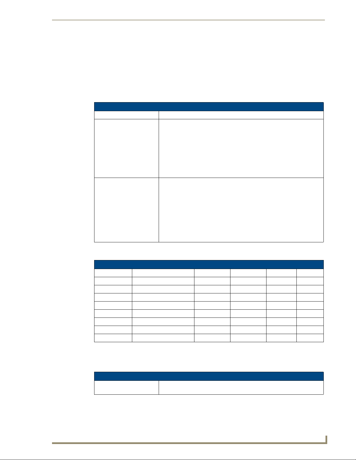
Programming
LED Disable/Enable Send_Commands
The following sections only apply to the integrated controller component of the NIs.
The following commands enable or disable the LEDs on the Integrated Controller. In the examples:
<DEV> = Port 1 of the device. Sending to port 1 of the NI-700 (affects all ports).
LED Send_Commands
Command Description
LED-DIS
Disable all LEDs (on 32 LED
hardware) for a port.
LED-EN
Enable the LED (on 32 LED
hardware) for a port
Regardless of whether or not the port is active, the LED will not be lit. Issue this
command to port 1 to disable all the LEDs on the Controller. When activity
occurs on a port(s) or Controller, the LEDs will not illuminate.
Syntax:
SEND_COMMAND <DEV>,"'LED-DIS'"
Example:
SEND_COMMAND Port_1,"'LED-DIS'"
Disables all the LEDs on Port 1 of the Controller.
When the port is active, the LED is lit. When the port is not active, the LED is
not lit. Issue the command to port 1 to enable the LEDs on the Controller
(default setting). When activity occurs on a port(s) or Controller, the LEDs
illuminate.
Syntax:
SEND_COMMAND <DEV>,'LED-EN'
Example:
SEND_COMMAND System_1,'LED-EN'
Enables the System_1 Controller's LEDs.
Port Assignments By NI Model
Port Assignments By NI Model
NI Model RS-232/422/485 IR/Serial IR/RX Relays I/O
NI-700 Ports 1 - 2 Port 3 Port 5 Port 4
NI-900 Port 1 Ports 2-4 Port 6 Port 5
NI-2000 Ports 1-3 Ports 5-8 Port 4 Port 9
NI-3000 Ports 1-7 Ports 9-16 Port 8 Port 17
NI-4000 Ports 1-7 Ports 9-16 Port 8 Port 17
NI-2100 Ports 1-3 Ports 5-8 Port 4 Port 9
NI-3100 Ports 1-7 Ports 9-16 Port 8 Port 17
NI-4100 Ports 1-7 Ports 9-16 Port 8 Port 17
RS232/422/485 Ports Channels
RS232/422/485 ports are Ports 1-2 (NI-700) and Port 1 (NI-900).
RS232/422/485 Ports Channels
255 - CTS push channel Reflects the state of the CTS input if a 'CTSPSH' command was sent to the
port.
NI Series WebConsole & Programming Guide
79
Page 88

Programming
RS-232/422/485 Send_Commands
RS-232/422/485 Send_Commands
Command Description
B9MOFF
Set the port's communication
parameters for stop and data
bits according to the software
settings on the RS-232 port
(default).
B9MON
Override and set the current
communication settings and
parameters on the RS-232
serial port to 9 data bits with
one stop bit.
CHARD
Set the delay time between
all transmitted characters to
the value specified (in 100
Microsecond increments).
CHARDM
Set the delay time between
all transmitted characters to
the value specified (in 1Millisecond increments).
CTSPSH
Enable Pushes, Releases,
and Status information to be
reported via channel 255
using the CTS hardware
handshake input.
CTSPSH OFF
Disable Pushes, Releases,
and Status information to be
reported via channel 255.
Disables 9-bit in 232/422/455 mode. By default, this returns the communication
settings on the serial port to the last programmed parameters. This command
works in conjunction with the 'B9MON' command.
Syntax:
SEND_COMMAND <DEV>,"'B9MOFF'"
Example:
SEND_COMMAND RS232_1,"'B9MOFF'"
Sets the RS-232 port settings to match the port's configuration settings.
Enables 9-bit in 232/422/455 mode. This command works in conjunction with
the 'B9MOFF' command.
Syntax:
SEND_COMMAND <DEV>,"'B9MON'"
Example:
SEND_COMMAND RS232_1,"'B9MON'"
Resets the RS-232 port's communication parameters to nine data bits, one
stop bit, and locks-in the baud rate.
Syntax:
SEND_COMMAND <DEV>,"'CHARD-<time>'"
Variable:
time = 0 - 255. Measured in 100 microsecond increments.
Example:
SEND_COMMAND RS232_1,"'CHARD-10'"
Sets a 1-millisecond delay between all transmitted characters.
Syntax:
SEND_COMMAND <DEV>,"'CHARDM-<time>'"
Variable:
time = 0 - 255. Measured in 1 millisecond increments.
Example:
SEND_COMMAND RS232_1,"'CHARDM-10'"
Sets a 10-millisecond delay between all transmitted characters.
This command turns On (enables) channel tracking of the handshaking pins. If
Clear To Send (CTS) is set high, then channel 255 is On.
Syntax:
SEND_COMMAND <DEV>,"'CTSPSH'"
Example:
SEND_COMMAND RS232_1,"'CTSPSH'"
Sets the RS232_1 port to detect changes on the CTS input.
This command disables tracking. Turns CTSPSH Off.
Syntax:
SEND_COMMAND <DEV>,"'CTSPSH OFF'"
Example:
SEND_COMMAND RS232_1,"'CTSPSH OFF'"
Turns off CTSPSH for the specified device.
80
NI Series WebConsole & Programming Guide
Page 89

RS-232/422/485 Send_Commands (Cont.)
Command Description
GET BAUD
Get the RS-232/422/485
port’s current communication
parameters.
HSOFF
Disable hardware handshaking (default).
HSON
Enable RTS (ready-to-send)
and CTS (clear-to-send)
hardware handshaking.
RXCLR
Clear all characters in the
receive buffer waiting to be
sent to the Master.
RXOFF
Disable the transmission of
incoming received characters to the Master (default).
RXON
Start transmitting received
characters to the Master
(default).
The port sends the parameters to the device that requested the information.
The port responds with:
<port #>,<baud>,<parity>,<data>,<stop> 485 <ENABLED | DISABLED>
Syntax:
SEND_COMMAND <DEV>,"'GET BAUD'"
Example:
SEND_COMMAND RS232_1,"'GET BAUD'"
System response example:
Device 1,38400,N,8,1 485 DISABLED
Syntax:
SEND_COMMAND <DEV>,"'HSOFF'"
Example:
SEND_COMMAND RS232_1,"'HSOFF'"
Disables hardware handshaking on the RS232_1 device.
Syntax:
SEND_COMMAND <DEV>,"'HSON'"
Example:
SEND_COMMAND RS232_1,"'HSON'"
Enables hardware handshaking on the RS232_1 device.
Syntax:
SEND_COMMAND <DEV>,"'RXCLR'"
Example:
SEND_COMMAND RS232_1,"'RXCLR'"
Clears all characters in the RS232_1 device's receive buffer waiting to be sent
to the Master.
Syntax:
SEND_COMMAND <DEV>,"'RXOFF'"
Example:
SEND_COMMAND RS232_1,"'RXOFF'"
Stops the RS232_1 device from transmitting received characters to the Master.
Enables sending incoming received characters to the Master. This command is
automatically sent by the Master when a 'CREATE_BUFFER' program
instruction is executed.
Syntax:
SEND_COMMAND <DEV>,"'RXON'"
Example:
SEND_COMMAND RS232_1,"'RXON'"
Sets the RS232_1 device to transmit received characters to the Master.
Programming
NI Series WebConsole & Programming Guide
81
Page 90

Programming
RS-232/422/485 Send_Commands (Cont.)
Command Description
SET BAUD
Set the RS-232/422/485
port's communication
parameters.
TSET BAUD
Temporarily set the RS-232/
422/485 port's
communication parameters
for a device.
TXCLR
Stop and clear all characters
waiting in the transmit out
buffer and stops transmission.
XOFF
Disable software
handshaking (default).
Syntax:
SEND_COMMAND <DEV>,"'SET BAUD
<baud>,<parity>,<data>,<stop> [485 <Enable | Disable>]'"
Variables:
baud = baud rates are: 115200, 76800, 57600, 38400, 19200, 9600, 4800,
2400, 1200, 600, 300, 150.
parity = N (none), O (odd), E (even), M (mark), S (space).
data = 8 data bits.
stop = 1 and 2 stop bits.
485 Disable = Disables RS-485 mode and enables RS-422.
485 Enable = Enables RS-485 mode and disables RS-422.
Note: The only valid 9 bit combination is (baud),N,9,1.
Example:
SEND_COMMAND RS232_1,"'SET BAUD 115200,N,8,1 485 ENABLE'"
Sets the RS232_1 port's communication parameters to 115,200 baud, no
parity, 8 data bits, 1 stop bit, and enables RS-485 mode.
TSET BAUD works the same as SET BAUD, except that the changes are not
permanent, and the previous values will be restored if the power is cycled on
the device.
Syntax:
SEND_COMMAND <DEV>,"'TSET BAUD
<baud>,<parity>,<data>,<stop> [485 <Enable | Disable>]'"
Variables:
baud = baud rates are: 115200, 57600, 38400, 19200, 9600, 4800, 2400,
1200, 600, 300.
parity = N (none), O (odd), E (even), M (mark), S (space).
data = 8 or 9 data bits.
stop = 1 or 2 stop bits.
485 Disable = Disables RS-485 mode and enables RS-422.
485 Enable = Enables RS-485 mode and disables RS-422.
Note: The only valid 9 bit combination is (baud),N,9,1.
Example:
SEND_COMMAND RS232_1,"'TSET BAUD 115200,N,8,1 485
ENABLE'"
Sets the RS232_1 port's communication parameters to 115,200 baud, no
parity, 8 data bits, 1 stop bit, and enables RS-485 mode.
Syntax:
SEND_COMMAND <DEV>,"'TXCLR'"
Example:
SEND_COMMAND RS232_1,"'TXCLR'"
Clears and stops all characters waiting in the RS232_1 device's transmit buffer.
Syntax:
SEND_COMMAND <DEV>,"'XOFF'"
Example:
SEND_COMMAND RS232_1,"'XOFF'"
Disables software handshaking on the RS232_1 device.
82
NI Series WebConsole & Programming Guide
Page 91

Programming
RS-232/422/485 Send_Commands (Cont.)
Command Description
XON
Enable software
handshaking.
Syntax:
SEND_COMMAND <DEV>,"'XON'"
Example:
SEND_COMMAND RS232_1,"'XON'"
Enables software handshaking on the RS232_1 device.
RS-232/422/485 Send_String Escape Sequences
This device also has some special SEND_STRING escape sequences:
If any of the 3 character combinations below are found anywhere within a SEND_STRING program
instruction, they will be treated as a command and not the literal characters.
In these examples: <DEV> = device.
RS-232/422/485 Send_String Escape Sequences
Command Description
27,17,<time>
Send a break character for a
specified duration to a
specific device.
27,18,0
Clear the ninth data bit by
setting it to 0 on all character
transmissions.
27,18,1
Set the ninth data bit to 1 for
all subsequent characters to
be transmitted.
27,19,<time>
Insert a time delay before
transmitting the next
character.
27,20,0
Set the RTS hardware
handshake's output to high
(> 3V).
Syntax:
SEND_STRING <DEV>,"27,17,<time>"
Variable:
time = 1 - 255. Measured in 100 microsecond increments.
Example:
SEND_STRING RS232_1,"27,17,10"
Sends a break character of 1 millisecond to the RS232_1 device.
Used in conjunction with the 'B9MON' command.
Syntax:
SEND_STRING <DEV>,"27,18,0"
Example:
SEND_STRING RS232_1,"27,18,0"
Sets the RS232_1 device's ninth data bit to 0 on all character transmissions.
Used in conjunction with the 'B9MON' command.
Syntax:
SEND_STRING <DEV>,"27,18,1"
Example:
SEND_STRING RS232_1,"27,18,1"
Sets the RS232_1 device's ninth data bit to 1 on all character transmissions.
Syntax:
SEND_STRING <DEV>,"27,19,<time>"
Variable:
time = 1 - 255. Measured in 1 millisecond increments.
Example:
SEND_STRING RS232_1,"27,19,10"
Inserts a 10 millisecond delay before transmitting characters to the RS232_1
device.
Syntax:
SEND_STRING <DEV>,"27,20,0"
Example:
SEND_STRING RS232_1,"27,20,0"
Sets the RTS hardware handshake's output to high on the RS232_1 device.
NI Series WebConsole & Programming Guide
83
Page 92

Programming
RS-232/422/485 Send_String Escape Sequences (Cont.)
Command Description
27,20,1
Set the RTS hardware
handshake's output to
low/inactive (< 3V).
Syntax:
SEND_STRING <DEV>,"27,20,1"
Example:
SEND_STRING RS232_1,"27,20,1"
Sets the RTS hardware handshake's output to low on the RS232_1 device.
IR / Serial Ports Channels
IR / Serial Ports Channels
CHANNELS: Description
00001 - 00229 IR commands.
00229 - 00253 May be used for system call feedback.
00254 Power Fail. (Used w/ 'PON' and 'POF' commands).
00255 Power status. (Shadows I/O Link channel status).
00256 - 65000 IR commands.
65000 - 65534 Future use.
The NI series of NetLinx Masters support Serial control via the IR/RX port when using
firmware version 300 or greater.
IR RX Port Channels
IR / Serial Ports Channels
00001 - 00255 PUSH and RELEASE channels for the received IR code.
IR/Serial Send_Commands
The following IR and IR/Serial Send_Commands generate control signals for external equipment. In
these examples: <DEV> = device.
IR/Serial Send_Commands
Command Description
CAROFF
Disable the IR carrier signal
until a 'CARON' command is
received.
CARON
Enable the IR carrier signals
(default).
Syntax:
SEND_COMMAND <DEV>,"'CAROFF'"
Example:
SEND_COMMAND IR_1,"'CAROFF'"
Stops transmitting IR carrier signals to the IR_1 port.
Syntax:
SEND_COMMAND <DEV>,"'CARON'"
Example:
SEND_COMMAND IR_1,"'CARON'"
Starts transmitting IR carrier signals to the IR_1 port.
84
NI Series WebConsole & Programming Guide
Page 93

IR/Serial Send_Commands (Cont.)
Command Description
CH
Send IR pulses for the
selected channel.
CP
Halt and Clear all active or
buffered IR commands, and
then send a single IR pulse.
CTOF
Set the duration of the Off
time (no signal) between IR
pulses for channel and IR
function transmissions.
CTON
Set the total time of IR pulses
transmitted and is stored in
non-volatile memory.
All channels below 100 are transmitted as two digits. If the IR code for ENTER
(function #21) is loaded, an Enter will follow the number. If the channel is
greater than or equal to (>=) 100, then IR function 127 or 20 (whichever exists)
is generated for the one hundred digit. Uses 'CTON' and 'CTOF' times for pulse
times.
Syntax:
SEND_COMMAND <DEV>,"'CH',<channel number>"
Variable:
channel number = 0 - 199.
Example:
SEND_COMMAND IR_1,"'CH',18"
This device performs the following:
• Transmits IR signals for 1 (IR code 11). The transmit time is set with the
CTON command.
• Waits until the time set with the CTOF command elapses.
• Transmits IR signals for 8 (IR code 18).
• Waits for the time set with the CTOF command elapses. If the IR code for
Enter (IR code 21) is programmed, the Controller performs the following
steps.
• Transmits IR signals for Enter (IR code 21).
• Waits for the time set with the CTOF command elapses.
You can set the Pulse and Wait times with the 'CTON' and 'CTOF' commands.
Syntax:
SEND_COMMAND <DEV>,"'CP',<code>"
Variable:
code = IR port's channel value 0 - 252 (253 - 255 reserved).
Example:
SEND_COMMAND IR_1,"'CP',2"
Clears the active/buffered commands and pulses IR_1 port's channel 2.
Off time settings are stored in non-volatile memory. This command sets the
delay time between pulses generated by the 'CH' or 'XCH' send commands in
tenths of seconds.
Syntax:
SEND_COMMAND <DEV>,"'CTOF',<time>"
Variable:
time = 0 - 255. Given in 1/10ths of a second. Default is 5 (0.5 seconds).
Example:
SEND_COMMAND IR_1,"'CTOF',10"
Sets the off time between each IR pulse to 1 second.
This command sets the pulse length for each pulse generated by the 'CH' or
'XCH' send commands in tenths of seconds.
Syntax:
SEND_COMMAND <DEV>,"'CTON',<time>"
Variable:
time = 0 - 255. Given in 1/10ths of a second. Default is 5 (0.5 seconds).
Example:
SEND_COMMAND IR_1,"'CTON',20"
Sets the IR pulse duration to 2 seconds.
Programming
NI Series WebConsole & Programming Guide
85
Page 94

Programming
IR/Serial Send_Commands (Cont.)
Command Description
GET BAUD
Get the IR port’s current
DATA mode communication
parameters.
GET MODE
Poll the IR/Serial port's
configuration parameters and
report the active mode
settings to the device
requesting the information.
IROFF
Halt and Clear all active or
buffered IR commands being
output on the designated
port.
POD
Disable previously active
'PON' (power on) or 'POF'
(power off) command
settings.
POF
Turn Off a device connected
to an IR port based on the
status of the corresponding
I/O Link input.
The port sends the parameters to the device that requested the information.
Only valid if the port is in Data Mode (see SET MODE command).
The port responds with:
<port #> <baud>,<parity>,<data bits>,<stop bits>
Syntax:
SEND_COMMAND <DEV>,"'GET BAUD'"
Example:
SEND_COMMAND IR_1,"'GET BAUD'"
System response example:
PORT 9 IR,CARRIER,IO LINK 0
The port responds with: <port #> <mode>,<carrier>,<io link channel>.
Syntax:
SEND_COMMAND <DEV>,"'GET MODE'"
Example:
SEND_COMMAND IR_1,"'GET MODE"
The system could respond with:
PORT 4 IR,CARRIER,IO LINK 0
Syntax:
SEND_COMMAND <DEV>,"'IROFF'"
Example:
SEND_COMMAND IR_1,"'IROFF"
Immediately halts and clears all IR output signals on the IR_1 port.
Channel 255 changes are enabled. This command is used in conjunction with
the I/O Link command.
Syntax:
SEND_COMMAND <DEV>,"'POD'"
Example:
SEND_COMMAND IR_1,"'POD"
Disables the 'PON' and 'POF' command settings on the IR_1 device.
If at any time the IR sensor input reads that the device is ON (such as if
someone turned it on manually at the front panel), IR function 28 (if available)
or IR function 9 is automatically generated in an attempt to turn the device back
OFF. If three attempts fail, the IR port will continue executing commands in the
buffer.
If there are no commands in the buffer, the IR port will continue executing
commands in the buffer and trying to turn the device OFF until a 'PON' or 'POD'
command is received. If the IR port fails to turn the device OFF, a PUSH and
RELEASE is made on channel 254 to indicate a power failure error. You can
only use the 'PON' and 'POF' commands when an IR device has a linked
I/O channel. Channel 255 changes are disabled after receipt of this command.
You can only use the 'PON' and 'POF' commands when an IR device has a
linked I/O channel.
Syntax:
SEND_COMMAND <DEV>,"'POF'"
Example:
SEND_COMMAND IR_1,"'POF'"
Sends power down IR commands 28 (if present) or 9 to the IR_1 device.
86
NI Series WebConsole & Programming Guide
Page 95

IR/Serial Send_Commands (Cont.)
Command Description
PON
Turn On a device connected
to an IR port based on the
status of the corresponding
I/O Link input.
PON (Cont.) Syntax:
PTOF
Set the time duration
between power pulses in
.10-second increments.
PTON
Set the time duration of the
power pulses in
.10-second increments
If at any time the IR sensor input reads that the device is OFF (such as if one
turned it off manually at the front panel), IR function 27 (if available) or IR
function 9 is automatically generated in an attempt to turn the device back ON.
If three attempts fail, the IR port will continue executing commands in the buffer
and trying to turn the device On.
If there are no commands in the buffer, the IR port will continue trying to turn
the device ON until a 'POF' or 'POD' command is received. If the IR port fails to
turn the device ON, a PUSH and RELEASE is made on channel 254 to indicate
a power failure error.
You can only use the 'PON' and 'POF' commands when an IR device has a
linked I/O channel. Channel 255 changes are disabled after receipt of this
command.
SEND_COMMAND <DEV>,"'PON'"
Example:
SEND_COMMAND IR_1,"'PON'"
Sends power up IR commands 27 or 9 to the IR_1 port.
This time increment is stored in permanent memory. This command also sets
the delay between pulses generated by the 'PON' or 'POF' send commands in
tenths of seconds. It also sets the delay required after a power ON command
before a new IR function can be generated. This gives the device time to power
up and get ready for future IR commands.
Syntax:
SEND_COMMAND <DEV>,"'PTOF',<time>"
Variable:
time = 0 - 255. Given in 1/10ths of a second. Default is 15 (1.5 seconds).
Example:
SEND_COMMAND IR_1,"'PTOF',15"
Sets the time between power pulses to 1.5 seconds for the IR_1 device.
This time increment is stored in permanent memory. This command also sets
the pulse length for each pulse generated by the 'PON' or 'POF' send
commands in tenths of seconds.
Syntax:
SEND_COMMAND <DEV>,"'PTON',<time>"
Variable:
time = 0 - 255. Given in 1/10ths of a second. Default is 5 (0.5 seconds).
Example:
SEND_COMMAND IR_1,"'PTON',15"
Sets the duration of the power pulse to 1.5 seconds for the IR_1 device.
Programming
NI Series WebConsole & Programming Guide
87
Page 96

Programming
IR/Serial Send_Commands (Cont.)
Command Description
SET BAUD
Set the IR port's DATA mode
communication parameters.
SET IO LINK
Link an IR or Serial port to a
selected I/O channel for use
with the 'DE', 'POD', 'PON',
and 'POF' commands.
SET MODE
Set the IR/Serial ports for IR
or Serial-controlled devices.
SP
Generate a single IR pulse.
Only valid if the port is in Data Mode (see SET MODE command).
Syntax:
SEND_COMMAND <DEV>,"'SET BAUD
<baud>,<parity>,<data>,<stop>'"
Variables:
baud = baud rates are: 19200, 9600, 4800, 2400, and 1200.
parity = N (none), O (odd), E (even), M (mark), S (space).
data = 7 or 8 data bits.
stop = 1 and 2 stop bits.
Example:
SEND_COMMAND IR_1,"'SET BAUD 9600,N,8,1'"
Sets the IR_1 port's communication parameters to 9600 baud, no parity, 8 data
bits, and 1 stop bit.
Note: The maximum baud rate for ports using SERIAL mode is 192000. Also,
SERIAL mode works best when using a short cable length (< 10 feet).
The I/O status is automatically reported on channel 255 on the IR port. The I/O
channel is used for power sensing (via a PCS or VSS). A channel of zero
disables the I/O link.
Syntax:
SEND_COMMAND <DEV>,"'SET IO LINK <I/O number>'"
Variable:
I/O number = 1 - 8. Setting the I/O channel to 0 disables the I/O link.
Example:
SEND_COMMAND IR_1,"'SET IO LINK 1'"
Sets the IR_1 port link to I/O channel 1. The IR port uses the specified I/O input
as power status for processing 'PON' and 'POF' commands.
Sets an IR port to either IR, Serial, or Data mode.
Syntax:
SEND_COMMAND <DEV>, 'SET MODE <mode>'"
Variable:
mode = IR, SERIAL, or DATA.
Example:
SEND_COMMAND IR_1,"'SET MODE IR'"
Sets the IR_1 port to IR mode for IR control.
Note: The maximum baud rate for ports using SERIAL mode is 192000. Also,
SERIAL mode works best when using a short cable length (< 10 feet).
Use the 'CTON' to set pulse lengths and the 'CTOF' for time Off between
pulses.
Syntax:
SEND_COMMAND <DEV>,"'SP',<code>"
Variable:
code = IR code value 1 - 252 (253-255 reserved).
Example:
SEND_COMMAND IR_1, "'SP',25"
Pulses IR code 25 on IR_1 device.
88
NI Series WebConsole & Programming Guide
Page 97

IR/Serial Send_Commands (Cont.)
Command Description
XCH
Transmit the selected channel IR codes in the format/
pattern set by the 'XCHM'
send command.
XCHM
Changes the IR output pattern for the 'XCH' send
command.
Syntax:
SEND_COMMAND <DEV>,"'XCH <channel>'"
Variable:
channel = 0 - 999.
Example:
For detailed usage examples, refer to the 'XCHM' command.
Syntax:
SEND_COMMAND <DEV>,"'XCHM <extended channel mode>'"
Variable:
extended channel mode = 0 - 4.
Example:
SEND_COMMAND IR_1,"'XCHM 3'"
Sets the IR_1 device's extended channel command to mode 3.
Mode 0 Example (default): [x][x]<x><enter>
SEND_COMMAND IR_1,"'XCH 3'"
Transmits the IR code as 3-enter.
SEND_COMMAND IR_1,"'XCH 34'"
Transmits the IR code as 3-4-enter.
SEND_COMMAND IR_1,"'XCH 343'"
Transmits the IR code as 3-4-3-enter.
Mode 1 Example: <x> <x> <x> <enter>
SEND_COMMAND IR_1,"'XCH 3'"
Transmits the IR code as 0-0-3-enter.
SEND_COMMAND IR_1,"'XCH 34'"
Transmits the IR code as 0-3-4-enter.
SEND_COMMAND IR_1,"'XCH 343'"
Transmits the IR code as 3-4-3-enter.
Mode 2 Example: <x> <x> <x>
SEND_COMMAND IR_1,"'XCH 3'"
Transmits the IR code as 0-0-3.
SEND_COMMAND IR_1,"'XCH 34'"
Transmits the IR code as 0-3-4.
SEND_COMMAND IR_1,"'XCH 343'"
Transmits the IR code as 3-4-3.
Mode 3 Example: [[100][100]…] <x> <x>
SEND_COMMAND IR_1,"'XCH 3'"
Transmits the IR code as 0-3.
SEND_COMMAND IR_1,"'XCH 34'"
Transmits the IR code as 3-4.
SEND_COMMAND IR_1,"'XCH 343'"
Transmits the IR code as 100-100-100-4-3.
Mode 4:
Mode 4 sends the same sequences as the 'CH' command. Only use Mode 4
with channels 0 - 199.
Programming
NI Series WebConsole & Programming Guide
89
Page 98

Programming
Input/Output Send_Commands
The following Send_Commands program the I/O ports on the Integrated Controller.
I/O ports: Port 4 (NI-700).
Channels: 1 - 8 I/O channels.
I/O Send Commands
Command Description
GET INPUT
Get the active state for the
selected channels.
SET INPUT
Set the input channel's active
state.
An active state can be high (logic high) or low (logic low or contact closure).
Channel changes, Pushes, and Releases generate reports based on their
active state. The port responds with either 'HIGH' or 'LOW'.
Syntax:
SEND_COMMAND <DEV>,"'GET INPUT <channel>'"
Variable:
channel = Input channel 1 - 8.
Example:
SEND_COMMAND IO,"'GET INPUT 1'"
Gets the I/O port's active state.
The system could respond with:
INPUT1 ACTIVE HIGH
An active state can be high (logic high) or low (logic low or contact closure).
Channel changes, Pushes, and Releases generate reports based on their
active state. Setting an input to ACTIVE HIGH will disable the ability to use that
channel as an output.
Syntax:
SEND_COMMAND <DEV>,"'SET INPUT <channel> <state>'"
Variable:
channel = Input channel 1 - 8.
state = Active state HIGH or LOW (default).
Example:
SEND_COMMAND IO,"'SET INPUT 1 HIGH'"
Sets the I/O channel to detect a high state change, and disables output on the
channel.
90
NI Series WebConsole & Programming Guide
Page 99

Terminal (Program Port/Telnet) Commands
Terminal (Program Port/Telnet) Commands
Overview
There are two types of terminal communications available on NetLinx Integrated Controllers:
Program Port - The "Program" port is a RS232 port located on the rear panel of the Master
that allows terminal communication with the Master. This type of terminal communication
requires that you are physically connected to the Master to access the configuration options
and commands supported. Since this method of terminal communication requires physical
proximity as well as a physical connection to the Master, it is the most secure form of terminal
communication.
For this reason, all Security Configuration options are only available via the Program port
(and cannot be access via Telnet).
Tel ne t - This type of terminal communication can be accessed remotely, via TCP/IP. It is a
less secure form of terminal communication, since it does not require a physical connection to
the Master to connect. Further, the Telnet interface exposes information to the network (which
could be intercepted by an unauthorized network client).
It is recommended that you make initial configurations as well as subsequent
changes via the WebConsole. Refer to the Onboard WebConsole User
Interface section on page 21.
Refer to the Terminal Commands section on page 93 for a listing of all commands available in a terminal
session.
Note that all commands in the table are available for both Program Port and Telnet sessions, with two
exceptions: "Help Security" and "Resetadminpassword". These commands are only available via a
Program Port connection.
Establishing a Terminal Connection Via the Program Port
To establish a terminal session via the Program Port, the PC COM (RS232) port on your PC must be
physically connected to the Program port on the NetLinx Master.
You will also need to know the current baud rate setting for the Master, so that you can verify that it
matches the settings on your PC.
1. In Windows, go to Start > Programs > Accessories > Communications to launch the
HyperTerminal application to open the Connection Description dialog.
2. Enter any text into the Name field and click OK. This action invokes the Connect to dialog.
3. Click the down-arrow From the Connect Using field, and select the PC COM port being used for
communication by the target Master and click OK when done.
4. From the Bits per second field, click the down-arrow and select the baud rate being used by the
target Master.
5. Configure the remaining communication parameters as follows:
• Data Bits: 8
• Parity: None
•Stop bits: 1
• Flow control: None
NI Series WebConsole & Programming Guide
91
Page 100

Terminal (Program Port/Telnet) Commands
6. Click OK to complete the communication parameters and open a new Terminal window.
7. Type echo on to view the characters while entering commands. If that does not work, press <Enter>
key on your keyboard.
It is very important to execute the 'logout' command prior to disconnecting from a
Master. Simply removing the RS-232 connector from the Program Port maintains
your logged-in status until you either return to logout via a new session or reboot the
target Master.
PC COM Port Communication Settings
Be sure that your PC's COM port and terminal program's communication settings match those in the
table below:
PC COM Port Communication Settings
Baud: 38400 (default)
Parity: None
Data Bits: 8
Stop Bits: 1
Flow Control: None
NetLinx Integrated Controllers - Port Assignments
Each of the NetLinx Integrated Controllers has specific port assignments:
NI-700 Port Assignments NI-900 Port Assignments
Port ICSP Por t # Port ICSP Port #
Serial Port #1 1
Serial Port #2 2
IR/Serial Port 3
I/O Port 4
IR RX Port 5
Serial Port #1 1
IR/Serial Port #1 2
IR/Serial Port #2 3
IR/Serial Port #3 4
I/O Port 5
IR RX Port 6
Establishing a Terminal Connection Via Telnet
1. In your Windows taskbar, go to Start > Run to open the Run dialog.
2. Type cmd in the Open field and click OK to open an instance of the Windows command interpreter
(Cmd.exe).
3. In the CMD (command), type "telnet" followed by a space and the Master’s IP Address info.
Example:
4. Press Enter.
Unless Telnet security is enabled, a session will begin with a welcome banner:
If Telnet security is enabled, type in the word login to be prompted for a Username and
5. Enter your username to be prompted for a password.
If the password is correct you will see the welcome banner.
If the password is incorrect, the following will be displayed:
>telnet XXX.XXX.XXX.XXX
Welcome to NetLinx vX.XX.XXX Copyright AMX Corp. 1999-2006
>
Password before gaining access to the Master.
92
NI Series WebConsole & Programming Guide
 Loading...