

Page 1

NetLinx Studio
v2.4 or higher
instruction manual
Software
Page 2

Software License and Warranty Agreement
LICENSE GRANT.
AMX grants to Licensee the non-exclusive right to use the AMX Software in the manner described in this License. The AMX Software
is licensed, not sold. The AMX Software consists of generally available programming and development software, product documentation, sample applications, tools and utilities, and miscellaneous technical information. Please refer to the README.TXT file on the
compact disc or download for further information regarding the
components of the AMX Software. The AMX Software is subject to restrictions on distribution described in this License Agreement.
YOU MAY NOT LICENSE, RENT, OR LEASE THE AMX SOFTWARE. You may not reverse engineer, decompile, or disassemble the
AMX Software.
INTELLECTUAL PROPERTY.
The AMX Software is owned by AMX and is protected by United States copyright laws, patent laws, international treaty provisions,
and/or state of Texas trade secret laws. Licensee may make copies of the AMX Software solely for backup or archival purposes. Licensee may not copy the written materials accompanying the AMX Software.
TERMINATION. AMX RESERVES THE RIGHT, IN ITS SOLE DISCRETION, TO TERMINATE THIS LICENSE FOR
ANY REASON AND UPON WRITTEN NOTICE TO LICENSEE.
In the event that AMX terminates this License, then Licensee shall return all copies of the AMX Software to AMX and certify in writing
that all copies have been destroyed.
PRE-RELEASE CODE.
Portions of the AMX Software may, from time to time, as identified in the AMX Software, include PRE-RELEASE CODE and such
code may not be at the level of performance, compatibility and functionality of the final code. The PRE-RELEASE CODE may not
operate correctly and may be substantially modified prior to final release or certain features may not be generally released. AMX is
not obligated to make or support any PRE-RELEASE CODE. ALL PRE-RELEASE CODE IS PROVIDED "AS IS" WITH NO WARRANTIES.
LIMITED WARRANTY.
AMX warrants that the AMX Software will perform substantially in accordance with the accompanying written materials for a period of
ninety (90) days from the date of receipt. AMX DISCLAIMS ALL OTHER WARRANTIES, EITHER EXPRESS OR IMPLIED, INCLUDING, BUT NOT LIMITED TO IMPLIED WARRANTIES OF MERCHANTABILITY AND FITNESS FOR A PARTICULAR PURPOSE,
WITH REGARD TO THE AMX SOFTWARE. THIS LIMITED WARRANTY GIVES YOU SPECIFIC LEGAL RIGHTS. Any supplements
or updates to the AMX SOFTWARE, including without limitation, any (if any) service packs or hot fixes provided to you after the expiration of the ninety (90) day Limited Warranty period are not covered by any warranty or condition, express, implied or statutory.
LICENSEE REMEDIES.
AMX's entire liability and your exclusive remedy shall be repair or replacement of the AMX Software that does not meet AMX's Limited Warranty and which is returned to AMX. This Limited Warranty is void if failure of the AMX Software has resulted from accident,
abuse, or misapplication. Any replacement AMX Software will be warranted for the remainder of the original warranty period or thirty
(30) days, whichever is longer. Outside the United States, these remedies may not available.
NO LIABILITY FOR CONSEQUENTIAL DAMAGES. IN NO EVENT SHALL AMX BE LIABLE FOR ANY DAMAGES WHATSOEVER
(INCLUDING, WITHOUT LIMITATION, DAMAGES FOR LOSS OF BUSINESS PROFITS, BUSINESS INTERRUPTION, LOSS OF
BUSINESS INFORMATION, OR ANY OTHER PECUNIARY LOSS) ARISING OUT OF THE USE OF OR INABILITY TO USE THIS
AMX SOFTWARE, EVEN IF AMX HAS BEEN ADVISED OF THE POSSIBILITY OF SUCH DAMAGES. BECAUSE SOME STATES/
COUNTRIES DO NOT ALLOW THE EXCLUSION OR LIMITATION OF LIABILITY FOR CONSEQUENTIAL OR INCIDENTAL DAMAGES, THE ABOVE LIMITATION MAY NOT APPLY TO YOU.
U.S. GOVERNMENT RESTRICTED RIGHTS. The AMX Software is provided with RESTRICTED RIGHTS. Use, duplication, or disclosure by the Government is subject to restrictions as set forth in subparagraph (c)(1)(ii) of The Rights in Technical Data and Computer Software clause at DFARS 252.227-7013 or subparagraphs (c)(1) and (2) of the Commercial Computer Software Restricted
Rights at 48 CFR 52.227-19, as applicable.
This Agreement replaces and supercedes all previous AMX Software License Agreements and is governed by the laws
of the State of Texas, and all disputes will be resolved in the courts in Collin County, Texas, USA. Should you have any
questions concerning this Agreement, or if you desire to contact AMX for any reason, please write: AMX Corporation,
3000 Research Drive, Richardson, TX 75082.
Page 3

Table of Contents
Table of Contents
NetLinx Studio (v2.4 or higher) ...............................................................................1
Overview ........................................................................................................................... 1
Supported Operating Systems and Minimum PC Requirements ...................................... 2
Supported operating systems: ................................................................................................. 2
PC Requirements:.................................................................................................................... 2
Other PC requirements: ........................................................................................................... 2
Supported File Types ........................................................................................................ 2
What's New Dialog ............................................................................................................ 3
WebUpdate ....................................................................................................................... 3
Software History2 Application ........................................................................................... 3
DIP Switch 2.0................................................................................................................... 3
The NetLinx Studio v2.4 Work Area ........................................................................5
Overview ........................................................................................................................... 5
Title Bar ............................................................................................................................. 5
Toolbars ............................................................................................................................ 5
Menu Bar........................................................................................................................... 6
Status Bar.......................................................................................................................... 6
Workspace Window........................................................................................................... 8
Workspace Window - Workspace Tab ..................................................................................... 8
Workspace Folder .................................................................................................................... 9
Project Folders ......................................................................................................................... 9
System Folders ........................................................................................................................ 9
System File Folders ............................................................................................................... 10
System Files........................................................................................................................... 10
File Mapping Information........................................................................................................ 10
Other key functions and features of the Workspace tab include:........................................... 10
Workspace File Context Menu ............................................................................................... 11
Workspace Window - Online Tree Tab .................................................................................. 12
Output Display Window ................................................................................................... 12
Output Display Window Context Menu .................................................................................. 13
File Transfer Tab Context Menu ............................................................................................ 14
Output Display Window - Notifications Tab............................................................................ 14
Output Display Window - Diagnostics Tab............................................................................. 14
Source Code Editor Windows ......................................................................................... 15
Source Code Editor Window - Features................................................................................. 15
Terminal Window............................................................................................................. 17
etLinx Studio (v2.4 or higher)
i
Page 4

Table of Contents
Using The Terminal Window .................................................................................................. 17
Terminal Window Context Menu ............................................................................................ 18
Watch Window ................................................................................................................ 18
Watch Window Context Menu ................................................................................................ 19
Using NetLinx Studio .............................................................................................21
The Netlinx Studio Workspace Wizard............................................................................ 21
Using the Workspace Wizard................................................................................................. 21
Building the Workspace ......................................................................................................... 23
The Netlinx Studio Code Wizard ..................................................................................... 23
Working With Workspace Files .............................................................................25
Overview ......................................................................................................................... 25
Opening Workspace Files ...................................................................................................... 26
Creating New (empty) Workspace Files................................................................................. 26
Import an Existing Project ...................................................................................................... 26
Copying and Pasting Projects ................................................................................................ 27
Deleting A Project From The Workspace............................................................................... 27
Importing Projects Into A Workspace..................................................................................... 27
Saving The Workspace .......................................................................................................... 28
Exporting Workspace Files For Distribution ........................................................................... 28
Importing Exported ("To Go") Workspace Files ..................................................................... 29
Viewing and Editing Workspace Properties ........................................................................... 30
Workspace File Context Menu ............................................................................................... 30
Working With Projects ...........................................................................................33
Overview ......................................................................................................................... 33
Opening Projects in NetLinx Studio v2.0 (or higher)....................................................... 33
Creating A New Project................................................................................................... 33
Building the Selected Project .......................................................................................... 34
Viewing And Editing Project Properties........................................................................... 34
Converting NetLinx Studio v1.2 Project Files.................................................................. 35
Project Folder Context Menu ................................................................................................. 36
Working With Systems and System Files ............................................................37
Working With Systems .................................................................................................... 37
Creating A New System .................................................................................................. 38
Adding An Existing System To a Project......................................................................... 39
Importing Systems Into A Project ........................................................................................... 39
Copying And Pasting Systems............................................................................................... 39
Deleting A System From A Project.................................................................................. 39
System Status: Active Vs. Inactive.................................................................................. 40
ii
NetLinx Studio (v2.4 or higher)
Page 5

Table of Contents
Designating The Active System ............................................................................................. 40
Configuring System-Level Communications Settings ..................................................... 40
Adding A File To A System ............................................................................................. 41
Drag And Drop Files Into A System ....................................................................................... 42
Removing A File From A System .................................................................................... 42
Building (Compiling Systems) ......................................................................................... 43
Building The Selected System ............................................................................................... 43
Building The Active System ................................................................................................... 43
Viewing And Editing System Properties .......................................................................... 44
System Folder Context Menu................................................................................................. 44
System Files.................................................................................................................... 45
Creating New System Files ............................................................................................. 46
File Types And Extensions..................................................................................................... 46
Identifiers vs. Disk Filenames.......................................................................................... 47
Viewing And Editing System File Properties ................................................................... 47
Device Mapping............................................................................................................... 48
Device Mapping Dialog .......................................................................................................... 48
DEVICE:PORT:SYSTEM (D:P:S) .......................................................................................... 49
To Remove Device Mapping Information from a File ............................................................. 50
System File Device Map Context Menu ................................................................................. 50
Working With System Source Code Files ....................................................................... 50
Adding A New Source Code File To A System ...................................................................... 51
Adding An Existing Source Code File To A System............................................................... 51
Removing A File From A System ........................................................................................... 52
Creating A Source Code File ................................................................................................. 52
Saving The Active File ........................................................................................................... 53
Saving All Open Files............................................................................................................. 53
File Revisions......................................................................................................................... 53
Designating The System's Master Source Code File............................................................. 54
Compiling Source Code Files................................................................................................. 54
UTF-8 Encoding ..................................................................................................................... 55
SRC File Extraction................................................................................................................ 55
ZIP File Extraction.................................................................................................................. 56
Source File Folder Context Menu .......................................................................................... 56
Source Code File Context Menu ............................................................................................ 57
Working With Include Files.............................................................................................. 57
NetLinx .AXI File .................................................................................................................... 57
Creating An Include File......................................................................................................... 57
Adding A New Include File To A System ............................................................................... 58
Adding An Existing Include File To A System ........................................................................ 58
etLinx Studio (v2.4 or higher)
iii
Page 6

Table of Contents
Include File Folder Context Menu .......................................................................................... 58
Include File Context Menu ..................................................................................................... 59
Working With Module Files ............................................................................................. 59
Duet (JAR) Module Files ........................................................................................................ 59
Minimum Support Requirements For Modules....................................................................... 60
Minimum support requirements for Duet modules (*.JAR):.................................................... 60
Adding A New Module File To A System ............................................................................... 60
Adding An Existing Module File To A System........................................................................ 60
Source Code Entry................................................................................................................. 61
Compiling Module Files.......................................................................................................... 62
Module File Folder Context Menu .......................................................................................... 62
Module File Context Menu ..................................................................................................... 62
Working With User Interface Files................................................................................... 63
Adding An Existing User Interface File To A System ............................................................. 63
Configuring NetLinx Source Code for KPD Files ................................................................... 64
Sample Netlinx Code ............................................................................................................. 65
User Interface File Folder Context Menu ............................................................................... 66
User Interface File Context Menu .......................................................................................... 66
Working With IR Files...................................................................................................... 66
Adding An Existing Ir File To A System ................................................................................. 66
IREDIT ................................................................................................................................... 67
Working With IREdit Database (*.IRN) Files.......................................................................... 67
Adding An IR File From the AMX IR Database ...................................................................... 67
Adding An IR File From an IREDIT User Database (*IRN) File ............................................. 68
IR File Folder Context Menu .................................................................................................. 69
IR File Context Menu ............................................................................................................. 69
Working With "Other" Files.............................................................................................. 70
Creating a Text File................................................................................................................ 70
Adding an Existing "Other" File To a System......................................................................... 70
Other File Folder Context Menu ............................................................................................. 71
Other File Context Menu ........................................................................................................ 71
Search Operations .......................................................................................................... 71
Using The Edit And Search Functions ................................................................................... 71
Searching Within the Active Source Code File ...................................................................... 71
Search And Replace Within The Active Source Code File .................................................... 72
Searching Across Multiple Files ............................................................................................. 73
Searching For Ir Library (IRL/IRV) Files................................................................................. 73
Printing Files ................................................................................................................... 74
Print Preview Window ............................................................................................................ 74
Print Dialog............................................................................................................................. 75
iv
NetLinx Studio (v2.4 or higher)
Page 7

Table of Contents
Programming ..........................................................................................................77
Overview ......................................................................................................................... 77
Source Code Editor Context Menu ........................................................................................ 77
Using The Code Wizard .................................................................................................. 78
Creating Events With the Code Wizard.................................................................................. 79
Creating Send_Commands With the Code Wizard................................................................ 79
Generating Constants From an IR File With the Code Wizard .............................................. 79
Code Wizard - Advanced Users ............................................................................................. 80
Code Wizard Dialog - Button Tab .......................................................................................... 80
Code Wizard Dialog - Channel Tab ....................................................................................... 81
Code Wizard Dialog - Level Tab ............................................................................................ 82
Code Wizard Dialog - Data Tab ............................................................................................. 83
Code Wizard Dialog - Send Command Tab........................................................................... 84
Code Wizard Dialog - IR Constant Tab.................................................................................. 84
Syntax Highlighting ................................................................................................................ 85
Default Syntax Highlighting Colors......................................................................................... 85
AutoComplete and AutoSuggest ............................................................................................ 86
Call Tips ................................................................................................................................. 87
Code Folding.......................................................................................................................... 88
Unicode Characters ............................................................................................................... 89
UTF-8 Encoding ..................................................................................................................... 89
Insert Section ......................................................................................................................... 89
Goto Section .......................................................................................................................... 90
Goto Line................................................................................................................................ 90
Goto Function Or Subroutine ................................................................................................. 90
Block Comment - Uncomment ............................................................................................... 90
Case Inversion ....................................................................................................................... 91
Clipboard Text Buffer ............................................................................................................. 91
Using The Clipboard Text Buffer ............................................................................................ 91
Find Matching Brace .............................................................................................................. 92
Sequentially Renumber Selection .......................................................................................... 92
Show Whitespace .................................................................................................................. 92
Show End Of Line .................................................................................................................. 92
Rescan Current Source File................................................................................................... 92
Advanced Editor Commands ................................................................................................. 92
Supported Regular Expression Special Characters............................................................... 93
Cut, Copy And Paste.............................................................................................................. 93
Undo/redo .............................................................................................................................. 94
Working With Bookmarks ................................................................................................ 94
Debugging ....................................................................................................................... 94
etLinx Studio (v2.4 or higher)
v
Page 8

Table of Contents
Debugging Source Code Files ............................................................................................... 94
To enter debug mode:............................................................................................................ 95
Using Single-step Mode ......................................................................................................... 95
Master Controller Debug Options........................................................................................... 96
Changing The Value Of A Watched Variable......................................................................... 96
Debug Mode Error Messages ................................................................................................ 96
Breakpoints ..................................................................................................................... 97
Using Breakpoints (NetLinx Only).......................................................................................... 97
Setting A Breakpoint .............................................................................................................. 97
Clearing Breakpoints.............................................................................................................. 98
Editing Breakpoints ................................................................................................................ 98
PUSH Messages............................................................................................................. 98
Insert Push Message Dialog .................................................................................................. 98
Find Push Message Dialog .................................................................................................... 99
Working With Unicode..................................................................................................... 99
Configuring NSX For Unicode Support .................................................................................. 99
Enabling UTF-8 ...................................................................................................................... 99
Enabling Unicode Compiling .................................................................................................. 99
Including the Unicode Library................................................................................................. 99
Defining a Unicode String Literal.......................................................................................... 100
Storing a Unicode String ...................................................................................................... 100
Working With Widechar Arrays and Unicode Strings........................................................... 100
Unicode - Character Case Mappings ................................................................................... 101
Unicode - Concatenating String ........................................................................................... 101
Unicode - Converting Between WIDECHAR and CHAR...................................................... 101
Unicode - Using FORMAT ................................................................................................... 101
Unicode - Reading and Writing To Files .............................................................................. 102
Unicode - Send Strings To A User Interface ........................................................................ 102
Right-to-Left Unicode Strings ............................................................................................... 103
Unicode - Compiler Errors.................................................................................................... 103
Using the Terminal Window .......................................................................................... 104
ASCII / HEX / DECIMAL CONVERSIONS TABLE ....................................................... 105
Compile Operations ............................................................................................. 107
Overview ....................................................................................................................... 107
Building the Workspace ................................................................................................ 107
Building the Selected Project ........................................................................................ 107
Building the Selected System ....................................................................................... 108
Building the Active System............................................................................................ 108
Designating the System's Master Source Code File ............................................................ 108
vi
NetLinx Studio (v2.4 or higher)
Page 9

Table of Contents
Compiling an Individual File .......................................................................................... 109
Compiler Errors and Warnings ...................................................................................... 110
Compiler Errors ............................................................................................................. 110
Compiler Warnings........................................................................................................ 113
Compiler Error Warnings Report Dialog............................................................................... 114
Disabling Compiler Warnings In Netlinx Code ..................................................................... 114
Run-Time Errors............................................................................................................ 114
Working With Online Devices ..............................................................................115
NetLinx Network Setup.................................................................................................. 115
Network Setup...................................................................................................................... 115
Working With the Online Device Tree ........................................................................... 116
Device Tree Elements.......................................................................................................... 117
Device States ....................................................................................................................... 118
Device Tree Context Menu .................................................................................................. 119
Checking Port Status ........................................................................................................... 119
Binding/Unbinding Devices .................................................................................................. 120
NetLinx Diagnostics - NetLinx Device Notification ........................................................ 121
Adding A Device To The Device Notification List................................................................. 121
Editing Device Notification Settings ..................................................................................... 122
Removing Devices From The Notifications List ................................................................... 123
NetLinx Diagnostics - NetLinx Internal Diagnostics Messages ..................................... 123
Debugging NetLinx Programs with Terminal or Telnet messages ....................................... 123
Buffering of the Notification and Diagnostic Tabs ................................................................ 127
NetLinx Diagnostics - NetLinx Device Emulation .......................................................... 127
NetLinx Diagnostics - NetLinx Device Control............................................................... 129
Viewing Push Results .......................................................................................................... 130
NetLinx Diagnostics - Netlinx Device Addressing ......................................................... 131
Changing The Device/System Address On A Netlinx Device .............................................. 131
Restoring The Default Device and System Numbers On A Netlinx Device ......................... 132
Using ID Mode To Change The Device Address On a NetLinx Device ............................... 132
NetLinx Diagnostics - URL Lists.................................................................................... 133
Creating a URL List.............................................................................................................. 133
NetLinx Diagnostics - Network Addressing ................................................................... 134
Changing the System Number On a Netlinx Master ............................................................ 134
Changing the IP Address On a NetLinx Device Using DHCP .............................................. 134
Setting the DNS Address For a Netlinx Master.................................................................... 134
Setting the IP Address For a NetLinx Master ....................................................................... 135
Changing the IP Address On a Netlinx Master (Use DHCP) ............................................... 135
Changing the IP Address On a Netlinx Master (Specify IP Address)................................... 136
etLinx Studio (v2.4 or higher)
vii
Page 10

Table of Contents
Setting NetLinx Time and Date ..................................................................................... 136
Rebooting the Master.................................................................................................... 137
Axcess/NetLinx Debugging ........................................................................................... 137
Debugging Source Code Files ............................................................................................. 137
Notes on Using Current Length (when the Total Length option is disabled):....................... 138
Master Controller Debug Options......................................................................................... 138
Changing The Value Of a Watched Variable ....................................................................... 139
Communications and File Transfers .................................................................. 141
Configuring Default Communications Settings.............................................................. 141
Configuring System-Level Communications Settings ................................................... 142
Configuring Terminal Communications Settings ........................................................... 143
Setting the Default Control Platform.............................................................................. 144
Changing The System Platform (Axcess / Netlinx) ....................................................... 144
Connecting To A Netlinx Master ................................................................................... 144
Configuring Virtual Netlinx Master Communication Settings (Netlinx Only) ......................... 144
Connecting To a Netlinx Master Via TCP/IP ........................................................................ 145
Connecting To a NetLinx Master Via Serial Port.................................................................. 146
Connecting To A NetLinx Master Via Modem ...................................................................... 146
Connecting To A Secured Netlinx Master ............................................................................ 147
If you don't connect: ............................................................................................................. 148
Connecting To an Axcess Master ................................................................................. 148
Connecting To An Axcess Master Via Serial Port................................................................ 148
Connecting To An Axcess Master Via Modem..................................................................... 148
File Transfer Operations ............................................................................................... 149
File Transfers Edit Sub-Menu .............................................................................................. 150
File Transfer Status Information ........................................................................................... 151
Canceling Transfers ............................................................................................................. 151
Transfer Errors And Definitions ............................................................................................ 151
Step 1: Adding Files To The Transfer Queue ............................................................... 152
Using The Quick Load Dialog .............................................................................................. 152
Adding Files To The Files To Send Queue .......................................................................... 153
Adding All Files Contained In An APW Or AXW File ........................................................... 153
Adding Files From A Specific Project/system ...................................................................... 153
Adding Individual System Files From The Open Workspace File ........................................ 154
Adding Orphan Files ............................................................................................................ 154
Adding Files To The Files To Receive Queue ..................................................................... 155
Step 2: Communication Settings................................................................................... 156
Listening For Netlinx Masters On The Subnet ..................................................................... 156
Configuring Communications Settings ................................................................................. 156
viii
NetLinx Studio (v2.4 or higher)
Page 11

Table of Contents
Configuring TCP/IP Communication Settings (Netlinx Only) ............................................... 156
Configuring Serial Communication Settings......................................................................... 157
Configuring Modem Communication Settings...................................................................... 157
Configuring Virtual Netlinx Master Communication Settings (Netlinx Only) ......................... 158
Configuring the Panel For Virtual Netlinx Master TCP/IP Transfers .................................... 158
Step 3: Device Mapping ................................................................................................ 159
Setting Device-File Mapping Information ............................................................................. 159
Editing Device Mapping Information .................................................................................... 159
Step 4: Transferring the Files ........................................................................................ 159
Sending Files To System Devices ....................................................................................... 159
Receiving Files From System Devices................................................................................. 159
Receiving Files Directly From A System Device (Serial Connections Only) ........................ 160
Virtual NetLinx Master (Masterless) Transfers .............................................................. 160
Virtual Netlinx Master USB Transfers .................................................................................. 160
Configuring the Touch Panel for Virtual NetLinx Master USB Transfers ............................. 161
AMX USB Driver Information For USB Enabled G4 Panels................................................. 161
Configuring NetLinx Studio for Virtual NetLinx Master Transfers......................................... 162
Transferring Files Using A Virtual Netlinx Master Usb Connection ...................................... 162
Virtual NetLinx Master TCP/IP Transfers ............................................................................. 163
Configuring The Touch Panel For Virtual Netlinx Master Tcp/ip Transfers .......................... 163
Configuring Netlinx Studio For Virtual Netlinx Master Tcp/ip Transfers ............................... 164
Transferring Files Using A Virtual Netlinx Master Tcp/ip Connection .................................. 164
Firmware Transfers ....................................................................................................... 165
Sending Firmware To a NetLinx Device (Kit File) ................................................................ 165
Sending Firmware To An Axcess Device (Tsk File)............................................................. 166
Netlinx Master Security ................................................................................................. 167
Enabling Security On Netlinx Masters.................................................................................. 167
Master Controller User Name and Password Dialog ........................................................... 168
Applying Security To Individual File Transfers ..................................................................... 168
Connecting To a Secured Netlinx Master ............................................................................ 169
If you don't connect: ............................................................................................................. 170
Tested Modems List ...................................................................................................... 170
Setting Program Preferences ..............................................................................171
Overview ....................................................................................................................... 171
Preferences Dialog - General Tab................................................................................. 171
Preferences Dialog - Axcess Compiler Tab .................................................................. 171
Preferences Dialog - Netlinx Compiler Tab ................................................................... 173
Preferences Dialog - Editor Tab .................................................................................... 174
Importing/Exporting Editor Preferences ............................................................................... 177
etLinx Studio (v2.4 or higher)
ix
Page 12

Table of Contents
Preferences Dialog - Commands Tab........................................................................... 177
Adding/Removing Commands From The Toolbars.............................................................. 177
Creating Custom Toolbars ................................................................................................... 178
Preferences Dialog - Toolbars Tab ............................................................................... 178
Preferences Dialog - Tools Tab .................................................................................... 178
Adding/Removing Application Shortcuts In The Tools Menu ............................................... 179
Preferences Dialog - Keyboard Tab.............................................................................. 179
Creating Custom Shortcut Keys ........................................................................................... 180
Preferences Dialog - Menu Tab .................................................................................... 180
Customizing The Menus ...................................................................................................... 181
Preferences Dialog - Diagnostics Tab........................................................................... 182
Preferences Dialog - Terminal Tab ............................................................................... 183
Preferences Dialog - File Transfer Tab......................................................................... 183
Preferences Dialog - Workspace Tab ........................................................................... 184
Troubleshooting ...................................................................................................185
NetLinx Debugger Not Stopping On A Breakpoint........................................................ 185
Symptoms ............................................................................................................................ 185
Cause................................................................................................................................... 185
Resolution ............................................................................................................................ 185
NetLinx Master Error - Device_ID Error ........................................................................ 186
Debug Option Disabled For Axcess Code File.............................................................. 186
Symptom .............................................................................................................................. 186
Cause................................................................................................................................... 186
Resolution ............................................................................................................................ 186
x
NetLinx Studio (v2.4 or higher)
Page 13

NetLinx Studio (v2.4 or higher)
Overview
NetLinx Studio v2 is a 32-bit Windows® application that allows you to program and maintain
entire control systems. NetLinx Studio fully supports both NetLinx and Axcess system
programming.
Beyond creating, editing and compiling source code in two programming languages (Axcess and
NetLinx), NetLinx Studio makes it easy to manage all of the files associated with an entire control
system (i.e. Master Source Code/Source Code (.AXS), Include (*.AXI) files, Module (.AXS or
.JAR) files, IR (*.IRL/*.IRV) files, User Interface (.TPD, .TP4, .KPD), and Other (any file type)
files) into one centralized location, as a System. To maintain multiple systems, one or more
Systems can be organized within a larger Project. A Project can contain as many Systems as are
required for a job. The Workspace Window organizes and displays all of these Project and System
files in a logical hierarchical tree structure.
To review a list of features that are new to this release, read the What's New document
(opens by default on startup, or select Help > What's New to open).
NetLinx Studio (v2.4 or higher)
The on-line help program is designed to offer key information to help to learn about and
use the NetLinx Studio program. Use the Table Of Contents on the left side of the help
window to navigate to a particular help topic, or press the F1 key while any dialog is open
to open the help topic associated with the active dialog.
The Help menu also contains shortcuts to the Axcess and NetLinx Keywords help files.
Each is a comprehensive listing of the commands included in each programming
language.
Additionally, you can view a brief description of each Axcess and/or NetLinx
programming command by highlighting any reserved keyword in an open code file and
pressing the F1 key. For example, highlight the reserved identifier "DO_PUSH" in a
source code editor window and hit F1. A help topic describing the DO_PUSH keyword
opens automatically.
Use the Index and Search tabs to perform more detailed searches.
Use the Browse Sequences to quickly browse related topics.
Click the AMX.COM toolbar button to access the www.amx.com home page.
Click the NetLinx Studio Online Help toolbar button to access an online version of this
help file. The online version of the help will always contain the most recent information,
including any possible updates.
etLinx Studio (v2.4 or higher)
1
Page 14

NetLinx Studio (v2.4 or higher)
Supported Operating Systems and Minimum PC Requirements
Supported operating systems:
Windows XP® Professional (service pack 1 or greater)
Windows 2000® (service pack 3 or greater)
You must have Administrator rights to install and run all required System files.
PC Requirements:
Pentium 233 MHZ processor (minimum requirement); 300 MHZ or faster recommended.
75 MB of free disk space (minimum requirement); 150 MB recommended.
128 MB of installed memory (RAM).
Minimum (VGA) screen resolution of 800x600.
Other PC requirements:
Windows-compatible CD-ROM drive.
Windows-compatible mouse (or other pointing device).
If the mouse wheel on your Microsoft® IntelliMouse® doesn't' work with NetLinx
Studio, try downloading the latest IntelliMouse drivers from Microsoft.
Supported File Types
NetLinx Studio supports the following file types for editing with the Source Code Editor:
Type Extension
Text files *.TXT
Source files *.AXS
Include files *.AXI
Block files *.AXB
Lib Files *.LIB
NetLinx Studio v1.2
Project files
The following file types are supported, but are edited using external AMX applications, as
described below:
*.PJS
Type Associated AMX Application Extension
TPD file TPDesign3 *.TPD
TP4 files TPDesign4 *.TP4
KPD files KPDesign *.KPD
IR files IREdit *.IRL, *.IRV
2
NetLinx Studio (v2.4 or higher)
Page 15

NetLinx Studio (v2.4 or higher)
NetLinx Studio will attempt to open all other file types (*.*) using the application
already associated with that file type in Windows.
What's New Dialog
The "What's New" dialog is displayed when NetLinx Studio is launched. This dialog provides a
(read-only) text file describing the features that are new to this release.
To prevent this dialog from being displayed every time the program is launched, select
the Don't Show Me Again option at the bottom of the dialog.
This dialog can always be accessed via the Help > What's New option.
WebUpdate
The AMX WebUpdate program is a stand-alone application that communicates with the AMX
website, allows a user to select from a list of available AMX Software programs to choose for
updating, determines the latest version of the selected applications, returns a listing of available
updates, allows a user to download the selected installation files, and upon request, launches the
installation of those downloads.
The WebUpdate application is not installed by NetLinx Studio, and must be installed
separately. If not found, NetLinx Studio will prompt you to download the application
from www.amx.com.
Select Help > Web Update to launch this application.
Refer to the WebUpdate on-line help for details and instructions.
Software History2 Application
The AMX Software History2 application provides the ability to display detailed information on
AMX hardware and software.
Click Tools > Software History to launch the application.
Refer to the AMX Software History 2 Application on-line help file for details and
instructions.
DIP Switch 2.0
DIP Switch 2.0 is an AMX application that graphically displays the dip switch settings necessary to
address Axcess, NetLinx and TXC+ devices and configure communications settings.
Click Tools > DIP Switch to launch the application.
Refer to the DIP Switch 2.0 on-line help file for details and instructions.
etLinx Studio (v2.4 or higher)
3
Page 16

NetLinx Studio (v2.4 or higher)
4
NetLinx Studio (v2.4 or higher)
Page 17

The NetLinx Studio v2.4 Work Area
The NetLinx Studio v2.4 Work Area
Overview
The NetLinx Studio work area contains the elements of the NetLinx Studio user interface.
Before jumping into a project, take a few moments to familiarize yourself with the main user
interface elements.
FIG. 1 The NetLinx Studio v2.4 Work Area
Title Bar
Displays the name of the application, and the name of the currently active file.
An asterisk (*) after the file name indicates that it contains unsaved changes.
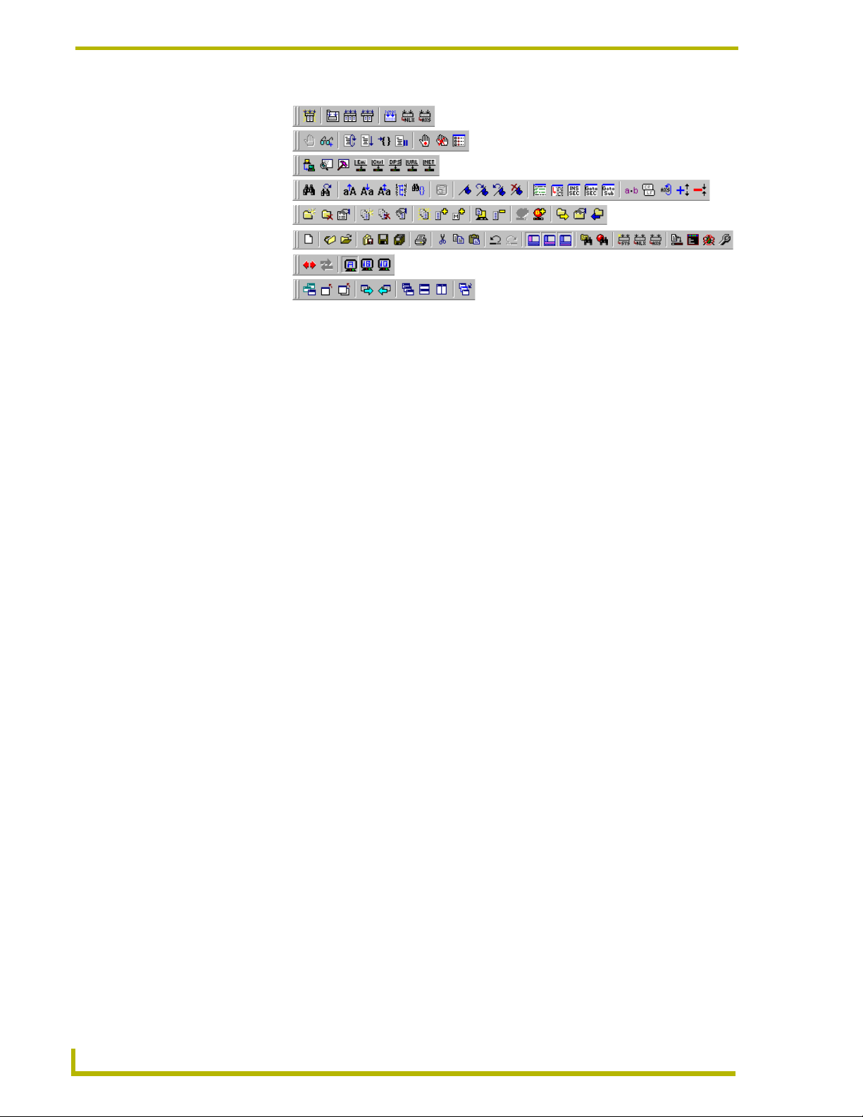
Toolbars
There are eight toolbars in NetLinx Studio.
Hover the mouse cursor over any toolbar button (for about one second) to display a"
Choose View > Toolbars to open the Toolbars sub-menu to view or hide the toolbars:
etLinx Studio (v2.4 or higher)
tooltip" describing the button.
5
Page 18
The NetLinx Studio v2.4 Work Area
Build toolbar
Debug Watch toolbar
Diagnostics toolbar
Edit toolbar
Project toolbar
Standard toolbar
Terminal toolbar
Window Mgmt toolbar
FIG. 2 Toolbars
See Also...
The Adding/Removing Commands From The Toolbars section on page 177.
The Creating Custom Toolbars section on page 178.
Menu Bar
The Menu Bar is located along the top of the application window, between the title bar and the
toolbars. Click on any of the main menu items to open the associated drop-down menu.
If you are running NetLinx Studio in Windows 2000, NT or XP, you may have to press
the ALT key to view the menu item hotkeys.
See Also...
The Customizing The Menus section on page 181
Status Bar
Click View > Status Bar (or click the toolbar button) to toggle (hide/show) the Status Bar. The
Status Bar displays general information, including communication status, a brief description of any
option in the program, cursor location, last Push received, COM port currently being used, network
IP address (NetLinx systems only) and current PC keyboard settings.
FIG. 3 Status Bar
The elements of the Status Bar are described below, from left to right:
6
NetLinx Studio (v2.4 or higher)
Page 19

The NetLinx Studio v2.4 Work Area
Program Status/Quick descriptions of program options - The far-left side of the status bar
displays quick descriptions of program options anytime you position the mouse cursor
over a toolbar button or menu item. This field also displays the total number of replaced
instances resulting from a search & replace operation.
Notifications Messages Status - Displays the status of NetLinx notification messages
(OFF/ON).
Diagnostics Messages Status - Displays the status of asynchronous notification messages
(OFF/ON).
Last Push Message and History - Displays the most recently received Push (if Push is
enabled via the Diagnostics > Enable Push Message Status Bar Display command), or
Push status (Push Enabled/Disabled). Left-mouse click on the push message displayed to
view a history of push messages. Then, right-mouse click within the list box to view the
available options.
Master Controller Connection Information - Displays the name and status of the active
communications port. If a TCP/IP connection exists, the current IP address is displayed.
If Virtual NetLinx Master is selected, then the Virtual NetLinx Master is displayed with
its System number.
Master Security Status - Indicates the current security status for the Master (locked =
Authentication Enabled, unlocked = Authentication disabled).
Cursor Location - Displays the cursor's location in the active Source Code Editor window
(line and column numbers).
Keyboard Settings - When a file is open (in a Source Code Editor window), the three
boxes on the far-right side of the status bar indicate the status of the following keyboard
settings:
OVR: Overwrite/Insert (OVR indicates that the keyboard is currently in overwrite
mode - new characters will replace or overwrite existing characters in the Source
Code Editor).
CAP: Caps Lock (CAPS indicates that the keyboard is currently in Caps Lock mode
- all letters typed will appear in upper case.
NUM: Number Lock (NUM indicates that the 10-key number/arrow keypad is set to
type numbers - arrow functions are disabled).
etLinx Studio (v2.4 or higher)
7
Page 20

The NetLinx Studio v2.4 Work Area
Workspace Window
Use the Workspace Window (FIG. 4) to manage Project files, System files and online devices. The
Workspace Window contains two tabs (Workspace and Online Tree), which display all open
Workspace files (containing Projects and their associated System files), and all devices currently
on-line, in a tree structure.
FIG. 4 Workspace Window (by default, displays the Workspace tab)
Click View > Workspace (or click the toolbar button) to toggle (show/hide) the
Workspace window.
Right-click inside the menu bar or menu area to display the View Control Context Menu,
where you can select to hide or display the NetLinx Studio toolbars.
Workspace Window - Workspace Tab
The Workspace tab contains a tree structure of all the available Projects (and Systems) contained
within a Workspace file. You may create multiple Projects within a Workspace. Within a Project,
you can create multiple Systems.
The Workspace view can be expanded to show all of the various elements within each opened
Project file, as shown below.
The first level within the open Workspace is the Project folder level.
The next level is the System(s) contained within the Project, each represented by a
System folder.
The third level contains the System File folders (Source, Include, Module, User Interface,
IR and Other).
8
NetLinx Studio (v2.4 or higher)
Page 21

The NetLinx Studio v2.4 Work Area
The 'Module' folder only appears if NetLinx is designated as the system platform (via
the Communication Settings dialog).
The fourth level contains all of the actual files that make up the System (.AXS, .AXI,
.TPD, .TKO, .TP4 .IRL/.IRV, and *.*).
The fifth and final level indicates the file mapping information for each file, as applicable.
FIG. 5 Workspace Window - Workspace Tab
Click on the "+" folder flags to expand the folders to expose any subfolders; click the "-" folder
flags to collapse the folders.
The hierarchical file structure of the Workspace tab is described below:
Workspace Folder
You can have one Workspace open at a time. A Workspace contains at least one Project,
and each Project contains at least one System.
Right-mouse click anywhere within the workspace tab to open the Workspace context
menu.
Project Folders
Right-mouse click on any Project folder to open the Project Folder context menu.
Expand any Project folder to display the System folder(s) contained in that Project.
System Folders
Each System has it's own platform (Axcess or NetLinx) setting along with the
communication information (i.e. IP address or COM port setting with the appropriate
baud rate, etc.).
Right-mouse click on any System folder to open the System Folder context menu.
etLinx Studio (v2.4 or higher)
9
Page 22

The NetLinx Studio v2.4 Work Area
Expand any System folder to display the six System File folders contained in that System
(Source, Include, Module, User Interface, IR and Other).
System File Folders
Expand any System File folder to display the System File(s) contained in that folder.
Right-click on any System File folder to open the System File Folder context menu
associated with that folder type.
System Files
Right-mouse click on any System File to open the System File context menu associated
with that file type.
Double-click any code file (Master Source Code, Source Code, Module or Include) to
open that file for viewing and/or editing in a Source Code Editor window.
Double-click any TPD file to open the TPDesign3 program (if it is installed).
Double-click any TP4 file to open the TPDesign4 program (if it is installed).
Double-click any KPD file to open the KPDesign program (if it is installed).
Double-click any IR file to open the IREdit program (if it is installed).
When you add a file to a System (Project > Add File To System), the file is automatically
placed (as a link) in the appropriate System File folder, based on it's file type.
You cannot have the same file referenced more than once within a system (i.e. cannot add
the same file name to the Source folder and the Other folder within the same System).
File Mapping Information
Any file that has device-file mapping information associated with it is represented in the
Workspace tab with a "+" flag.
Click on the "+" symbol to expand the view to indicate the File Mapping Information.
Other key functions and features of the Workspace tab include:
You can drag and drop files from Explorer into the appropriate sub-folders within a
System.
All files are linked files associated with a system, not copies of files from one location to
another.
For the TPD/4, IR files and other source code files, you have the ability to map multiple
devices to the selected file.
The Master Source Code file will always be mapped automatically to device address
0:1:0 for NetLinx masters or 0 for Axcess masters.
10
You have the ability to copy a selected System folder to paste into another or the same
Project folder.
You have the ability to designate a single source code file as the Master Source Code file.
NetLinx Studio (v2.4 or higher)
Page 23

The NetLinx Studio v2.4 Work Area
Right-click on any open area inside the Workspace tab to open the Workspace Window
Context Menu.
Workspace File Context Menu
Right-click on the Workspace file (in the Workspace tab of the Workspace Window) to open the
Workspace File context menu. This context menu contains various Workspace file-level commands
and options, including:
New Workspace Closes the currently open Workspace file, and starts a new (empty)
Workspace Wizard Launches the Workspace Wizard, which steps you through the pro-
Open Workspace Opens the Open Workspace dialog, where you can locate and select
Close Workspace Closes the Workspace file. The program prompts you to close the files
Save Workspace Saves the Workspace file, under its current name and location.
Save Workspace As Opens the Save Workspace As dialog, where you can specify a new
Build Workspace Builds (compiles) the Workspace (including all contained Projects).
Export Workspace Files
To G o
Import From Exported
Workspace File
New Project Opens the New Project Properties dialog, which allows you to assign
Import a Project Opens the Open Workspace dialog, where you can locate and select
Paste Project You can copy and paste Projects by selecting Copy Project from the
Collapse Tree Collapses the Project/System/File tree to show only the Workspace
Expand To System Level Expands the Project/System/File tree to show the Workspace,
Docking view Changes the Workspace Window to a dockable window that can be
Hide Hides the Workspace Window.
Quick Load Workspace This option allows you to access the File Transfer dialog, already con-
Workspace Properties Opens the Workspace Properties dialog, where you can view the
workspace (no Project/System associated until you add them manually).
cess of creating a new Workspace with a Project/System.
an existing Workspace (.APW) file. You can have only one Workspace
open at any time, so in the event that you have a Workspace open, it
will be replaced by the one you open.
associated with the Workspace before closing them.
name and/or location for the saved Workspace file.
The progress and results of the build can be viewed in the Status tab
of the Output Display window.
Opens the Export Workspace File To Go dialog, where you can export
the Workspace for distribution as an AXW file. AXW files preserve all
relative file path information for the Projects, Systems and System
files contained in the Workspace making them ideal for distribution to
remote sites.
Opens the Select AXW File dialog, where you can select a previously
exported "To Go" (AXW) file to import into the program.
an Identifier and general properties for a new Project. Once created,
the new project is added to the Workspace.
a Workspace (.APW) file. This invokes the Import Components From a
Workspace dialog. Use the dialog to select a specific Project contained in the Workspace.
Project Folder context menu, and selecting the Paste Project command.
and its Project(s).
Project(s) and System(s).
resized and moved to anywhere within the NetLinx Studio work area.
figured to send all files in the Workspace (active Project/System only)
to the Master associated with the active System.
basic properties of the open Workspace. The options in this dialog
also allow you to edit the Workspace Identifier and Description.
etLinx Studio (v2.4 or higher)
11
Page 24
The NetLinx Studio v2.4 Work Area
Workspace Window - Online Tree Tab
The Online Tree tab of the Workspace Window (FIG. 6) displays an Online Device tree for either
the NetLinx or Axcess Master Controller. This tab displays a list of devices detected to be currently
online by the Master Controller (and the firmware version for each). The Device Tree also provides
port status information for each device.
FIG. 6 Workspace Window - Online Tree Tab
Refer to the Working With the Online Device Tree section on page 116 for more information.
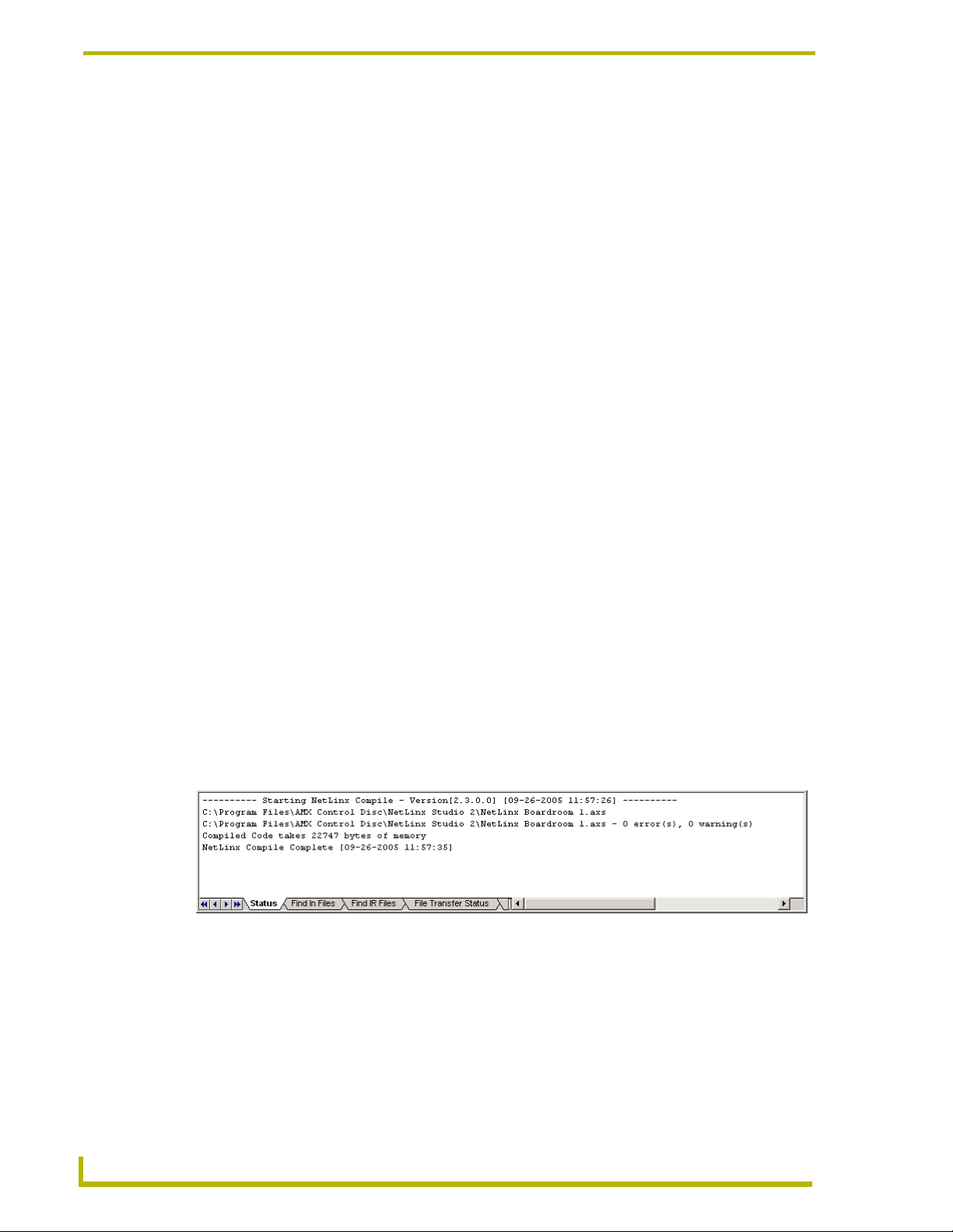
Output Display Window
Select View > Output (or click the toolbar button) to toggle (show/hide) the Output Display
window (FIG. 7).
FIG. 7 Output Display Window (by default opens to the Status tab)
12
NetLinx Studio (v2.4 or higher)
Page 25

The NetLinx Studio v2.4 Work Area
There are 6 tabs contained in the dockable Output Display window:
Status Tab The Status tab displays build information pertaining to the last compila-
tion of source code files, as well as port status information.
Double click on a line containing an compiler error message to open
the file in a Source Code Editor window, with the cursor positioned at
the beginning of the line containing the indicated error.
Note: The version number of the compiler (NetLinx or Axcess) is displayed in the Status tab, whenever source code is being compiled.
Find In Files tab The Find In Files tab displays the results of a Tools > Find In Files
Find IR Files tab The Find IR Files tab displays the results of a Tools > Find IRL/IRV
File Transfer Status tab The File Transfer Status tab of the Output Display Window displays the
Notifications tab The Notifications tab displays several types of auto-notification mes-
Diagnostics tab The Diagnostics tab displays internal system diagnostics messages
search operation.
Right-mouse click in the view to see the available options to save or
copy the contents of this list.
search operation.
To add one or more of the listed IR files to a System in the open Workspace, select a file (or Ctrl + click to select multiple files), then drag and
drop the file(s) into the System folder of the System that you want to
add the file(s) to. This invokes the File Properties dialog, where you can
change the Identifier, File Name and Description for each file that you
are adding to the System.
Double click on a listed file to open it for viewing/editing in the IREdit
utility program.
status on the list of files that are have been or are being transferred.
sages from one or more specified NetLinx devices.
See the NetLinx Diagnostics - NetLinx Device Notification section on
page 121 for details.
sent by the NetLinx master controller
Right-click inside any of the Output Display window tabs to access the Output Display window
context menu.
Output Display Window Context Menu
Right-click inside any of the Output Display window tabs (Status, Find In Files, Find IR Files, File
Transfer Status, Notifications or Diagnostics) to open the Output Display window context menu.
As indicated, some of the options below are not relevant to all tabs.
The options in this menu include:
Enable/Disable
Asynchronous Notifications
(Notifications tab only)
Enable/Disable
Diagnostics Messages
(Diagnostics tab only)
Copy All Items Copies all items in the list to the clipboard.
Copy Selected Items Copies only the selected items in the list to the clipboard.
Stops or starts the asynchronous notifications messages that
are sent by the NetLinx master controller without visiting the
menu bar.
Stops or starts the internal system diagnostics messages that
are sent by the NetLinx master controller without visiting the
menu bar.
etLinx Studio (v2.4 or higher)
13
Page 26

The NetLinx Studio v2.4 Work Area
Save All Items Saves all items to a user-defined file. You will be prompted for
Save Selected Items Saves only the selected items to a user-defined file. You will
Compiler Error /Warning Report This option scans the contents of the Status tab, and then lists
Find
(Notifications and
Diagnostics tabs only)
Clear Clears all the items within the list.
a file name to save the contents of the tab.
be prompted for a file name to save the contents of the tab.
each compiler error and warning (one per line) in the Status
tab. This option invokes the Compiler Error Warnings Report
dialog, which allows you to specify wether you want to include
compiler Errors, Warnings or both in the report. By default,
Errors and Warnings are both selected.
Search for text within the tab, via the Find dialog. You may
search up or down the tab based on the current cursor location within the tab. The search can be case sensitive. When
the text is found in the tab, the program highlights the row and
scrolls the row into view.
File Transfer Tab Context Menu
Right-click on any item listed in the File Transfer Status tab of the Output Display window to
access the File Transfer Tab Context Menu:
Copy All Items Copies all items in the list to the clipboard.
Copy Selected Items Copies only the selected items in the list to the clipboard.
Save All Items Saves all items to a user-defined file. You will be prompted for a file
Save Selected Items Saves only the selected items to a user-defined file. You will be
Clear Clears all the items within the list.
Cancel Current Transfer Cancels the current transfer.
Cancel Selected
Transfer Items
Cancel Remaining
Transfer Items
Cancel All Transfer
Items
name to save the contents of the tab.
prompted for a file name to save the contents of the tab.
WARNING: Canceling during a file transfer may leave the target device
in an unstable state.
Cancels only transfer items that have been selected (highlighted).
Cancels all remaining transfers in the list, but allows the current transfer to complete.
Cancels all transfer items in the list, including the current one (if applicable).
14
Output Display Window - Notifications Tab
The Notification tab of the Output Display Window displays the asynchronous notification
messages being received from the master controller. You can right-mouse click in the tab to see the
available options to save or copy the contents of this list.
Output Display Window - Diagnostics Tab
The Diagnostics tab of the Output Display Window displays all internal system diagnostic
messages that are generated by a NetLinx master controller. You can right-mouse click in the tab to
see the available options to save or copy the contents of this list.
NetLinx Studio (v2.4 or higher)
Page 27

The NetLinx Studio v2.4 Work Area
Source Code Editor Windows
Use Source Code Editor windows (FIG. 8) to display, view and edit Axcess and NetLinx source
code files. You can have multiple files open at any time. Each code file is opened in a separate
Source Code Editor window.
FIG. 8 Source Code Editor Window
Use the Source Code Editor windows to generate and edit Axcess and/or NetLinx code files.
NetLinx Studio features a Code Wizard that steps you through the process of
generating several different types of code.
Do not attempt to open .LIB or .SYC files for editing in the Source Code Editor. Doing
so could cause program failure.
Source Code Editor Window - Features
Source Code Editor window features include:
Unicode Characters Select Unicode Edit from the Edit menu, or the Source Code
Editor Context Menu (right-click inside the editor window to
access) to open the Enter Text... dialog which allows you to
insert unicode characters in your code, at the cursor position
in the editor.
etLinx Studio (v2.4 or higher)
15
Page 28

The NetLinx Studio v2.4 Work Area
Code folding Fold levels can be used to simplify the view in the Source
Auto-suggest and
Auto-complete functionality
Syntax Highlighting The text in the Editor windows is syntax highlighted for
Drag and drop Support Drag and drop any supported file type from Explorer into the
Floating Window Source Code Editor windows are moveable and resizeable.
Windows > New Window Use the New Window option in the Window menu to open
Source Code Editor
context menu
Columnar Cut, Copy
and Paste
Insert Section Use the Edit > Insert Section option to insert a (empty) sec-
Goto Section Use the Edit > Goto Section option to move the cursor to the
Undo and Redo The Edit > Undo and Redo commands allow unlimited Undo/
Make Selection Uppercase and
Make Selection Lowercase
Sequentially Renumber Selection Use the Edit > Sequentially Renumber Selection command
Block Comment-Uncomment The Edit > Block Comment-Uncomment option allows you to
Code Editor windows by allowing you to "fold" each major
section of the code (DEFINE_DEVICE,
DEFINE_CONSTANT, DEFINE_TYPE, etc.) so that only the
header row is visible. This way, you only see the section(s)
that you are actually working in. In order to use fold levels,
you must first enable the option in the Editor tab of the Preferences dialog (by default, this option is disabled).
As you type in a variable name, device name or a language
reserved word, the program will suggest a name that has
been previous defined within the source code (this option is
toggled on and off in the Preference dialog - Editor Options
tab). Press the Tab key to incorporate an Auto-Suggest.
increased readability with a default set of colors. Use the
options in the Editor Options tab of the Preferences dialog to
customize various aspects of the Source Code editor windows (i.e. syntax highlighting, auto-indent, show/hide line
numbers and clipboard text buffer settings).
Note: Syntax highlighting assigns different colors to different
types of data in your Source Code file. Use syntax highlighting to make your code easier to read and manage. For
example, you could syntax highlight all comments to yellow,
all identifiers to red and strings to blue to make them more
easily identifiable in your code file.
Source Code Editor to open that file in a new Source Code
Editor window.
Drag and drop selected text to another Editor window (at the
cursor location), or to another location within the same Editor
window.
Use the options in the Window menu to arrange (cascade or
tile) multiple windows.
the same code file in multiple Editor windows. This feature
allows you to view and edit different locations in a large code
file.
Right-click anywhere within a Source Code Editor window to
open the Source Code Editor context menu.
Hold down the Alt key and select text with the left mouse button for columnar Cut, Copy, and Paste operations.
tion of code at the cursor position.
beginning of a selected section of code in the active Editor
window.
Redo operations.
Use the Edit > Make Selection Uppercase and Make Selection Lowercase commands to automatically change the case
on a selection of text.
to sequentially renumber selected number text in the active
Editor window.
block comment-uncomment selected text in the active Editor
window.
16
NetLinx Studio (v2.4 or higher)
Page 29

The NetLinx Studio v2.4 Work Area
Indentation To indent a block of text, select text and press the Tab key.
Other Features include: • Multiple clip-board buffer capabilities.
Use Shift + Tab to remove the indentation.
• Ability to print an entire file.
• Mouse wheel support.
Terminal Window
NetLinx Studio provides a terminal interface to NetLinx and Axcess devices that support an
interactive terminal mode. Select Tools > Terminal (or click the toolbar button) to invoke the
Term in al Window.
Key features of the Terminal window (accessible through the Terminal window context menu) are
described below:
Paste operations - Text data contained in the clipboard can be pasted into the terminal
window. However, text can only be pasted when the Terminal window is connected
(online), and only the first line of text in the clipboard will be pasted.
All characters pasted in the Terminal window are not pasted into the window directly,
regardless of the current position of the caret. Rather, they are sent out the port to the
device just as if they had been typed directly from the keyboard. This means that you
will not necessarily see the text that was pasted unless echoing is currently enabled
on the device. Also, carriage-return characters are not appended to the pasted text
(even if the clipboard text contains one). You must press the return key to enter a
pasted command.
Terminal communication settings - The Terminal window has it's own dedicated
communications settings. Refer to the Master Communication Settings help topic for
information on configuration of the Terminal communication settings.
The Terminal window does not support:
Cut operations.
Editing operations within the window, other than to input characters at the cursor (the text
in the terminal window actually reflects what has been received from the device. Text that
is typed in the window will not appear unless echoing is currently enabled on the device).
Using The Terminal Window
Select Tools > Terminal (or click the toolbar button) to open the Terminal window.
The Terminal window puts the Master Controller into dumb terminal mode. Anything that is typed
on the screen exits through the Master communications port, and anything coming in from the
communications port is displayed in the Terminal window. Use the Terminal window to
communicate directly with the Master Controller and to debug RS-232-controlled devices.
You cannot use the Terminal window while a communication port is in use for a file
transfer or debug operation.
Type "ECHO ON" in the Terminal window to display messages.
If the Terminal window becomes unresponsive, close and re-open the window.
To leave the Terminal Emulator window active for a long session, click the Terminal
etLinx Studio (v2.4 or higher)
Locks the Port option in the General tab of the Preferences dialog.
17
Page 30

The NetLinx Studio v2.4 Work Area
Use the Terminal Options tab of the Preferences dialog to modify the behavior and
change the appearance of the Terminal window.
To use the Terminal window with NetLinx systems, you must be connected to the Master
via the PROGRAM port. Otherwise, you can use Windows TelNet for terminal control of
NetLinx systems.
Terminal Window Context Menu
Several of the key functions of the Terminal Window are accessible via the Terminal Window
context menu. To open this context menu, right-click inside the Terminal Window. The options
include:
Display Click to open the Display sub-menu, which contains view options for the Termi-
Clear Clears the contents of the Terminal Window.
Save To File Opens the Save As dialog, which allows you to save the contents of the Termi-
Disconnect Disconnects the Terminal. The terminal window background turns a light shade
Last commands At the bottom of this menu is a list of the last commands entered. Use the items
nal Window. The options are ASCII, HEX (hexadecimal) and DEC (decimal).
nal Window as a text file (.txt).
of gray, to indicate that it is disconnected.
in this list as shortcuts to recently used commands.
Watch Window
The Watch window is displayed when Start Debugging is selected from the Debug menu (or the
Debug Watch toolbar). The Watch window is a dockable window that allows you to view and edit
the contents of specified variables within a compiled Axcess or NetLinx program. Also, you can
control the execution of the mainline of a compiled Axcess or NetLinx program. The Watch
window contains three tabs (Watch1-Watch3), which allow you to watch up to three separate sets/
lists of specified variables.
The Watch window consists of a table with four columns:
Name Enter the name of the watched variable in this column.
Line (NetLinx only) Enter line number (in the Source Code file) where the variable is declared.
Length This column displays the length of the watched variable.
Value This column displays the value of the watched variable.
Display This column displays the format of the variable (ASCII, Decimal, Hexadeci-
mal, Octal, ASCII or Binary).
18
You can also drag and drop a variable from the Source Code Editor window into the
debug window.
Right-click inside the Watch Window to access the Watch Window context menu.
NetLinx Studio (v2.4 or higher)
Page 31

The NetLinx Studio v2.4 Work Area
Watch Window Context Menu
Right-click inside the Watch Window to access the Watch Window context menu, described below:
Refresh List Refreshes the contents of the Watch Window.
Add Variable Opens a text field in the Name column, to allow you to add a variable to
Add Variable From List Opens the List of Watched Variables dialog, where you can select a
Delete Variable Deletes the selected variable from the Watch Window.
Delete All Variables Deletes all variables from the Watch Window.
Total Length Sets the viewing mode for arrays to show the total length of the array in
Step Mode Toggles the step mode between Run and Single Step mode.
Single Step In NetLinx systems, this command executes a single instruction in the
the Watch Window.
variable to add to the Watch Window from a list of all variables located in
the TKN file of a compiled NetLinx source code file.
the Length column of the Watch Window. All of the locations of the array
are displayed, regardless of the Current Length value of the array. By
default, this option is enabled. When disabled, the viewing mode shows
Current Length in the Length column.
source file; in Axcess systems, it executes a single line of code in the
Mainline.
etLinx Studio (v2.4 or higher)
19
Page 32

The NetLinx Studio v2.4 Work Area
20
NetLinx Studio (v2.4 or higher)
Page 33

Using NetLinx Studio
The Netlinx Studio Workspace Wizard
A key feature of NetLinx Studio (v2.x) is the Workspace Wizard. The Workspace Wizard quickly
steps you through the process of creating a new Workspace, with a Project and a System.
Using the Workspace Wizard
The NetLinx Studio Workspace Wizard provides an quick and easy way to create a new Workspace
(.APW) file with one Project and one System. It presents a series of dialogs, which allow you to
enter workspace information based on specific questions.
1. To start the Workspace Wizard, select File > New (or click the toolbar button).
2. In the New dialog, select Workspace Wizard and click OK.
3. In the Workspace Wizard dialog, enter a name (up to 128 characters) for the new Workspace
file in the text field (required).
To enter an optional text description for the new Workspace, click the Workspace File
Description button, and enter the description in the Workspace File Description dialog (2000
characters max). Click OK to return to the Workspace Wizard dialog.
Using NetLinx Studio
4. Click Next to proceed to the Workspace File Location dialog.
5. Specify the target location for the Workspace file in the text field, or click the Browse button
(to the right of the text field) to locate and select a target directory via the Browse For Folder
dialog.
6. Click Next to proceed to the Project Identifier dialog.
7. Enter an identifier (name) for the new Project in the text field.
To enter additional information for the new Project, click the Project Information button, and
fill in the Project Information (up to 128 characters) and Description (up to 2,000 characters)
text fields in the Project Information dialog (all fields in this dialog are optional). Click OK to
return to the Project Identifier dialog.
8. Click Next to proceed to the System Type dialog.
9. Use the radio buttons to select which type of System to add to the Project (NetLinx or Axcess).
This dialog also includes the option to add the System later, in which case the Workspace
Wizard is complete. Select either NetLinx or Axcess and click Next to proceed to the System
Information dialog.
10. Enter a name for the new System in the text field.
To enter an optional text description for the new System, click the Workspace File
Description button, and enter the description in the System Description dialog (2,000
characters max). Click OK to return to the System Information dialog.
11. Click Next to proceed to the Assign System ID dialog.
12. To associate a System ID to the new System, enter the System ID in the text field. By default
the ID is set to zero (
etLinx Studio (v2.4 or higher)
0 = this System).
21
Page 34

Using NetLinx Studio
13. Click Next to proceed to the System Communications dialog. This dialog displays the current
14. Click Communication Settings to set the communication settings for this System, in the
These settings become the default communication settings for all new Workspace
files, until they are manually changed.
15. Click Next to proceed to the Master Source Code File Selection dialog.
16. Use the radio buttons to select the type of Master Source Code file to create for this System:
Master Communication Settings in a read-only text box.
Communication Settings dialog.
Create an empty AXS File - This option generates an AXS file that is totally empty (no
templates used):
a. Click Next to proceed to the Master Source Code File Name dialog.
b. Enter a name (up to 128 characters) for the new (empty) Master Source Code File.
c. Click Source Code File Description to enter a description (up to 2,000 characters) in the
Source Code File Description dialog, and click OK to return to the Master Source Code
File Name dialog.
d. Click Next to proceed to the New File Location dialog.
e. Specify the target location for the new file in the text field (click the Browse button to
locate and select a target directory via the Browse For Folder dialog).
f. Click Next to complete the Wizard.
Add an existing AXS File to the System - This option adds an existing AXS file to the
System as the Master Source Code File:
a. Click Next to proceed to the Existing Master Source File Location dialog.
b. Enter a path and filename of the desired Master Source Code File, or click the Browse
button to locate and select the desired AXS file via the Open dialog.
c. Click Source Code File Description to enter an optional description (up to 2,000
characters) in the Source Code File Description dialog, and click OK to return to the
Existing Master Source File Location dialog.
d. Click Next to complete the Wizard.
Create an AXS File using Templates - This option generates an AXS file using either
the NetLinx or Axcess template, depending on the System type specified in Step 9. This
option results in a Source Code file that is formatted with header/footer information and
all of the main sections of a typical Source Code File of the selected type:
a. Click Next to proceed to the File Template dialog.
22
b. Enter a name (up to 128 characters) for the new Master Source Code File.
c. Click Next to proceed to the New File Location dialog.
d. Specify the target location for the new file in the text field (click the Browse button to
locate and select a target directory via the Browse For Folder dialog).
NetLinx Studio (v2.4 or higher)
Page 35

Using NetLinx Studio
e. Click Source Code File Description to enter an optional description (up to 2,000
characters) in the Source Code File Description dialog, and click OK to return to the
Master Source Code File Name dialog.
f. Click Next to proceed to the New File Location dialog.
g. Specify the target location for the new file in the text field (click the Browse button to
locate and select a target directory via the Browse For Folder dialog).
h. Click Next to complete the Wizard.
Add the Master Source Code File Later - This option allows you to exit the Workspace
Wizard at this point, and manually specify the System's Master Source Code File later.
17. In the Wizard Completed dialog, click Finish to exit the Wizard.
The new Workspace (with your new Project containing the new System) is represented in the
Workspace tab of the Workspace Window.
Building the Workspace
One advantage to the Workspace concept employed by NetLinx Studio (v2.0 or later) is that you
can choose to build (compile) the entire Workspace. That is, every Source Code, Include, and
Module file contained within the open Workspace can be compiled with a single command: Build
Workspace.
There are several ways to access the Build Workspace command - via the Build menu, the
Workspace context menu (in the Workspace tab of the Workspace Window), or via the toolbar
button.
To compile the open Workspace:
1. Select Build > Build Workspace (or click the toolbar button).
Any errors detected by the program before the build operation starts are listed in the Pre-Build
Errors dialog. This dialog gives you the option of ignoring the errors and continuing with the
build.
2. The status and results of the build are displayed in the Status tab of the Output Display
Window.
The Netlinx Studio Code Wizard
Select Tools > Code Wizard to launch the NetLinx Studio Code Wizard. The Code Wizard
consists of a series of dialogs that help you quickly generate various types of Axcess and NetLinx
code segments. The wizard can help construct the following type of code segments:
Button Events
Channel Events
Level Events
Data Events
Send Commands
IR Constants
etLinx Studio (v2.4 or higher)
23
Page 36

Using NetLinx Studio
The Code Wizard can be toggled to display individual dialogs for all the above functionality, for
use by advanced users.
When the Wizard generates a new code segment, it is automatically inserted in the active Source
Code file, in the appropriate section of the code.
Refer to Using The Code Wizard section on page 78 for details.
24
NetLinx Studio (v2.4 or higher)
Page 37

Working With Workspace Files
Overview
NetLinx Studio utilizes a new concept for working with multiple projects/files simultaneously: the
Workspace file.
A Workspace represents at least one Project (containing at least one System), however a Workspace
can contain multiple Projects. Each Project in turn can contain multiple Systems. At any time, you
can create a Workspace file (via the File > Save Workspace option). Once created, you can re-open
that Workspace file to recall the NetLinx Studio workspace, exactly as it was when the Workspace
file was created.
All Workspace information is saved in an XML formatted file with the .APW file extension.
The File > Save Workspace command only saves the Workspace (APW) file itself,
and does not save changes made to the System files contained in the Workspace.
Use the File > Save All command to save the Workspace file and all of the System
files it contains.
One advantage of the Workspace file is that it serves as a time-saver: Once you have saved a
Workspace file, (containing a particular set of Projects, Systems and System Files), the next time
you open the application, you can simply open the single Workspace file (File > Open Workspace)
to load the Projects/Systems it contains. This way you bypass the need to open each Project,
System and System File individually.
Working With Workspace Files
All Projects and associated Systems and System files are linked to the Workspace, so that you can
add and remove Projects and Systems without having to make copies of the files. NetLinx Studio
also allows you to copy and paste Projects within the Workspace; in the case that you need to create
several similar Projects you can quickly generate multiple Projects and modify each one as
necessary.
Since all System files are linked to the Workspace, when you open a file for editing,
you are opening and editing the actual file, not a local copy. It is important to
understand that in the event that the file is linked to multiple Systems, any changes
made to the file will be reflected in every instance that the file is used (not just the
System that you were in when the changes were made). Even if you don't have
multiple links to the same file, you should still be careful about altering the file. If you
are linking to a file that other people might use, they will be affected by the changes
you make to the file. So, if you intend to make changes to a System file, and you want
those changes to be specific to only one System in the Workspace, you should make
a copy of the original file (under a different name), make your changes, then remove
the original file from the System and link the new file to the System.
Workspace files also allow you to build (compile) multiple Projects/Systems. The Build Workspace
command compiles every file contained in the Workspace.
It is important to note that in NetLinx Studio (v2.0 and later), there is no concept of Projects outside
the context of a Workspace. A Project can only be opened by adding it to a Workspace. This is to
support the file linking aspect of the program.
etLinx Studio (v2.4 or higher)
25
Page 38

Working With Workspace Files
Other features of the Workspace file include:
You can import other Project or Systems folders from previously saved Workspace files.
You can copy and paste existing Projects and Systems within a Workspace.
You can edit the identifier that is used to display the workspace name in the tree display
You can export all the files associated with the Workspace (including the Workspace file)
Opening Workspace Files
1. Select Open Workspace from the File menu or the Workspace context menu (or click the
toolbar button) to open the Open Workspace dialog.
2. Use the options in this dialog to locate and select a Workspace (.APW).
3. Click Open to open the selected Workspace file.
Since you can only have one Workspace open at a time, the program will prompt you
to save any changes before closing the active Workspace and opening the selected
one.
along with the description for the Workspace file via the Workspace Properties dialog.
into a .ZIP file.
Creating New (empty) Workspace Files
To create a new empty Workspace:
Right-click on the Workspace folder to access the Workspace context menu, and select
New Workspace.
Before the new Workspace is created, the program will prompt you to save any changes
made to the currently open Workspace (if applicable).
A new Workspace file is created. As indicated in the Workspace tab, this Workspace contains no
Projects/Systems. All Projects/Systems and associated files must be added manually.
To create a new Workspace with a Project and System, use the Workspace Wizard.
Import an Existing Project
You can import existing Projects into the active workspace, via the Import a Project option in the
Workspace context menu.
To import an existing Project into the active Workspace:
1. Right-click on the Workspace folder (in the Workspace tab of the Workspace window) and
select Import a Project from the Workspace context menu.
26
2. In the Open Workspace dialog, locate and select the Workspace (.APW) file that the Project
you want to import currently belongs to.
The same Project can be included in more than one Workspace file.
NetLinx Studio (v2.4 or higher)
Page 39

Working With Workspace Files
3. In the Import Components From a Workspace dialog, use the check boxes to select which
Project(s) contained in the specified Workspace file to import.
4. Click OK.
If the selected Project(s) contain any identifiers that are already being used by the
target Workspace, the program prompts you to change them. In this case, use the
Import Name Change dialog to specify a new identifier for the imported Project.
5. The specified Project(s) should now appear as part of the open Workspace.
Copying and Pasting Projects
One advantage to the concept of Workspaces is that you can easily copy and paste Projects (and all
of the associated Systems and System Files) within a Workspace. This allows you to develop a core
Project which you can then copy, paste and modify as necessary. In cases where there are only
minor variations from one Project to the next, this can be a real timer-saver.
To copy and paste a Project (within a Workspace):
1. Open a Workspace (in the Workspace tab of the Workspace Window) and click to select
(highlight) a Project folder.
2. Right-click on the Project folder and select Copy Selected Project from the Project Folder
context menu.
3. Right-click on the Workspace file, and select Paste Project from the Workspace context menu.
Deleting A Project From The Workspace
When you "delete" a Project from the open Workspace, no System files are actually deleted from
the hard drive; the Project is simply removed from the open Workspace.
To delete a Project from the Workspace:
1. Click to select the Project that you want to remove (in the Workspace tab of the Workspace
Window).
2. Select Delete Project from the Project menu, the Project Folder context menu, or click the
toolbar button.
3. The program prompts you to confirm removing the selected Project.
4. Click Ye s to remove the Project.
Importing Projects Into A Workspace
You can import existing Projects into the active workspace, via the Import a Project option in the
Workspace context menu.
To import an existing Project into the active Workspace:
1. Right-click on the Workspace folder (in the Workspace tab of the Workspace window) and
select Import a Project from the Workspace context menu.
2. In the Open Workspace dialog, locate and select the Workspace (.APW) file that the Project
you want to import currently belongs to.
etLinx Studio (v2.4 or higher)
27
Page 40

Working With Workspace Files
The same Project can be included in more than one Workspace file.
3. In the Import Components From a Workspace dialog, use the check boxes to select which
Project(s) contained in the specified Workspace file to import.
4. Click OK.
If the selected Project(s) contain any identifiers that are already being used by the
target Workspace, the program prompts you to change them. In this case, use the
Import Name Change dialog to specify a new identifier for the imported Project.
5. The specified Project(s) should now appear as part of the open Workspace.
Saving The Workspace
Click File > Save Workspace (or click the toolbar button) to save the Workspace using
Select File > Save Workspace As to save the file under a new name. If you save the
the current filename and identifier.
Workspace under a different name, the program will ask you wether you want to change
the Workspace Identifier (the name that appears at the top of the Workspace tab of the
Workspace Window) to match the new filename.
Exporting Workspace Files For Distribution
The Export Workspace Files To Go option in the Project menu allows you to export the open
Workspace for distribution as an AXW file. AXW files preserve all relative file path information
for the Projects, Systems and System files contained in the Workspace, making them ideal for
distribution to remote sites.
As is indicated in this dialog, there are three major points to understand when exporting your
Workspace files:
All files will reside in the same directory as the APW file upon extraction of the AXW
file.
No directory/path information is required for the "To Go" APW File Name.
You may enter non-existing folders and the program will create them for you.
1. Select Export Workspace Files To Go from the Project menu, the Workspace context menu,
or click the toolbar button to open the Export Workspace Files To Go dialog.
2. By default, the name and target directory of the AXW file to be created matches the name of
the open Workspace file. Use the Name of the "To G o" File text field to change the name and
target directory for the resulting AXW file, if desired. Use the Browse button to navigate to a
different folder.
3. By default, the name and target directory of the APW file to be created (and included in the
AXW "To Go" file) matches the name of the open Workspace file, with "_Exported" appended
to the end (for example "NetLinx Boardroom.APW" becomes "NetLinx
Boardroom_Exported.APW" once it is extracted from the AXW file). Use the "To Go"
28
NetLinx Studio (v2.4 or higher)
Page 41

Working With Workspace Files
Workspace Filename To Create text field to change the name and target directory for the
resulting AXW file, if necessary.
4. Use the radio buttons in the Export Options area of the dialog to specify exporting the Full
Wo rk sp ac e (all Projects and Systems included), or only the currently active Project (Only
Active Project) or the currently active System (Only Active System). By default, the program is
configured to export the entire Workspace file.
5. Use the checkboxes in the Export Options area to select additional options as desired:
Select the Include User IRN Database(s) checkbox to include any user-defined .IRN (IR
database) files in the resulting AXW file. If the selected Workspace file does not include
any user-defined IRN files, this option is disabled.
Select the Include Module Files that are not part of the Workspace checkbox to
include AXS (*.TKO) and Duet (*.JAR) Module files that are needed for a successful
NetLinx compile and link, but have not been added to the Workspace. Module files are
found by searching the "Module Files" directories defined on the NetLinx Compiler tab
of the Preferences dialog. If the selected Workspace file does not utilize Module files, this
option is disabled.
Select the Exclude All Source Code/AXS and Duet Module Files checkbox to exclude
source code and Duet module files from the resulting AXW file. Excluding AXS/AXI
files will result in device mappings of the exported AXW file to be set to "Custom". Since
no source files will be part of the exported AXW, all device mappings will need to be
resolved in the newly created APW file.
Naturally, the previous two options are mutually exclusive. If you select one, the other is
disabled.
Select the Include the Compiled TKN/TOK File checkbox to include the compiled
TKN/TOK file in the exported APW file.
Select the Include the Complied SRC File checkbox to include the compiled SRC file
(in addition to the compiled TKN/TOK file). Note that this option is only enabled if the
Include the compiled TKN/TOK file option is selected.
The Progress bar indicates the progress of the export operation.
Once the export operation is done, detailed results of the operation are listed in the Export
Workspace Files Report dialog.
Importing Exported ("To Go") Workspace Files
1. Select Project > Import From Exported Workspace File (or click the toolbar button) to access
the Select AXW File dialog.
2. Locate and select the desired AXW file, and click Open.
3. In the Import From Exported Workspace File dialog, the file selected in the Select AXW File
dialog is listed in the AXW File to Extract From field. Use the browse button to locate and
select a different file, if necessary.
4. The target directory indicated in the Extract To field matches the source directory for the
selected file by default. Use the browse button to locate and select a different target directory
for the Workspace file, if necessary.
etLinx Studio (v2.4 or higher)
29
Page 42

Working With Workspace Files
5. Click Extract to extract the selected Workspace file to the specified directory. If a file of the
same name already exists in the target directory, the NetLinx Studio Extraction Overwrite
dialog prompts you to either overwrite the existing file (Ye s or Ye s To All ), to preserve the
existing file (No), or to cancel the operation.
6. Once the file is extracted, the Workspace file is automatically loaded, and is represented in the
Workspace tab of the Workspace Window.
If a Workspace file is open when the file is extracted, the program prompts you to
close the currently open Workspace, as well as any associated System files.
Viewing and Editing Workspace Properties
Use the Workspace Properties dialog to view and/or edit general properties of the open Workspace.
To access this dialog, select Workspace Properties from the Project menu, the Workspace context
menu, or click the toolbar button.
You can edit the Identifier and Description fields, but the File Name and Creation Date are readonly.
Identifier The Workspace Identifier can have a maximum of 128 characters.
File Name The File Name cannot be changed and is only for display.
Description The Description text is optional and can have a maximum of 2,000 characters.
Creation Date This read-only field indicates the creation date of the open Workspace.
Conversion Date If a NetLinx Studio v2.0 (or higher) workspace file was converted from a
NetLinx Studio v1.2 *.PJS file, the Conversion Date will also be displayed.
Workspace File Context Menu
Right-click on the Workspace file (in the Workspace tab of the Workspace Window) to open the
Workspace File context menu. This context menu contains various Workspace file-level commands
and options, including:
New Workspace Closes the currently open Workspace file, and starts a new (empty)
Workspace Wizard Launches the Workspace Wizard, which steps you through the pro-
Open Workspace Opens the Open Workspace dialog, where you can locate and select
Close Workspace Closes the Workspace file. The program prompts you to close the files
Save Workspace Saves the Workspace file, under its current name and location.
Save Workspace As Opens the Save Workspace As dialog, where you can specify a new
Build Workspace Builds (compiles) the Workspace (including all contained Projects).
workspace (no Project/System associated until you add them manually).
cess of creating a new Workspace with a Project/System.
an existing Workspace (.APW) file. You can have only one Workspace
open at any time, so in the event that you have a Workspace open, it
will be replaced by the one you open.
associated with the Workspace before closing them.
name and/or location for the saved Workspace file.
The progress and results of the build can be viewed in the Status tab
of the Output Display window.
30
NetLinx Studio (v2.4 or higher)
Page 43

Working With Workspace Files
Export Workspace Files
To G o
Import From Exported
Workspace File
New Project Opens the New Project Properties dialog, which allows you to assign
Import a Project Opens the Open Workspace dialog, where you can locate and select
Paste Project You can copy and paste Projects by selecting Copy Project from the
Collapse Tree Collapses the Project/System/File tree to show only the Workspace
Expand To System Level Expands the Project/System/File tree to show the Workspace,
Docking view Changes the Workspace Window to a dockable window that can be
Hide Hides the Workspace Window.
Quick Load Workspace This option allows you to access the File Transfer dialog, already con-
Workspace Properties Opens the Workspace Properties dialog, where you can view the
Opens the Export Workspace File To Go dialog, where you can export
the Workspace for distribution as an AXW file. AXW files preserve all
relative file path information for the Projects, Systems and System
files contained in the Workspace making them ideal for distribution to
remote sites.
Opens the Select AXW File dialog, where you can select a previously
exported "To Go" (AXW) file to import into the program.
an Identifier and general properties for a new Project. Once created,
the new project is added to the Workspace.
a Workspace (.APW) file. This invokes the Import Components From a
Workspace dialog. Use the dialog to select a specific Project contained in the Workspace.
Project Folder context menu, and selecting the Paste Project command.
and its Project(s).
Project(s) and System(s).
resized and moved to anywhere within the NetLinx Studio work area.
figured to send all files in the Workspace (active Project/System only)
to the Master associated with the active System.
basic properties of the open Workspace. The options in this dialog
also allow you to edit the Workspace Identifier and Description.
etLinx Studio (v2.4 or higher)
31
Page 44

Working With Workspace Files
32
NetLinx Studio (v2.4 or higher)
Page 45

Working With Projects
Overview
A Project in NetLinx Studio contains one or more Systems (a System represents a control system
(an Axcess or NetLinx Master, one or more user-interface devices and various types of controlled
devices on the bus). Projects are represented by Project folders in the Workspace tab of the
Workspace Window. A Workspace can contain several Projects (which in turn can contain multiple
Systems).
In NetLinx Studio (v2.0 and later), all Projects and associated Systems and System files are linked
to the Workspace, so that you can add and remove Projects and Systems without having to make
copies of the files. NetLinx Studio (v2.0 and later) also allows you to copy and paste Projects
within the Workspace; in the case that you need to create several similar Projects you can quickly
generate multiple Projects and modify each one as necessary.
Since all System files are linked to the Workspace, when you open a file for editing,
you are opening and editing the actual file, not a local copy. It is important to
understand that in the event that the file is linked to multiple Systems, any changes
made to the file will be reflected in every instance that the file is used (not just the
System that you were in when the changes were made).
Working With Projects
Even if you don't have multiple links to the same file, and instead have only a single link, you still
need to be careful about altering the file. If you are linking to a file that other people might use, they
will be affected by the changes you make to the file. So, if you intend to make changes to a System
file, and you want those changes to be specific to only one System in the Workspace, you should
make a copy of the original file (under a different name), make your changes, then remove the
original file from the System and link the new file to the System.
Opening Projects in NetLinx Studio v2.0 (or higher)
In NetLinx Studio version 2.0 or later, Projects are always contained within a Workspace, and there
is no concept of a Project outside of a Workspace. So, rather than opening a Project directly (like
you would have in NetLinx Studio v1.2), you must open the Workspace that contains the Project
you want to work on.
Creating A New Project
In order to create a Project, you must first open or create a Workspace file. When a Project is
created, it is automatically added to the open Workspace.
To create new Project:
1. Select New Project from the Project menu or the Workspace context menu (or click the toolbar
button) to open the New Project Properties dialog.
A Workspace must be open for these options to be enabled.
2. Enter an Identifier (name) for the Project (required). The Identifier can have a maximum of
128 characters, and must be unique within the open Workspace file.
etLinx Studio (v2.4 or higher)
33
Page 46

Working With Projects
3. Enter Dealer, Designer, Sales Order, Purchase Order info (maximum of 128 characters each),
4. Click OK to add the new Project to the active Workspace.
Building the Selected Project
You can select to compile a single Project within the open Workspace, using the Build Project
command. When you compile a Project, every Source Code, Include, and Module file contained in
all of the Systems within the selected Project are compiled.
There are several ways to access the Build Project command - via the Build menu, the Project
Folder context menu (in the Workspace tab of the Workspace Window), or via the toolbar button.
To compile a Project:
1. Click to select and highlight the Project that you want to compile (in the Workspace tab of the
2. Select Build > Build <Project Name> Project.
and a Description for the Project (maximum of 2,000 characters). These fields are all optional.
Workspace Window).
Any errors detected by the program before the build operation starts are listed in the
Pre-Build Errors dialog.
This dialog gives you the option of ignoring the errors and continuing with the build.
3. The status and results of the build are displayed in the Status tab of the Output Display
Window.
Viewing And Editing Project Properties
Use the Project Properties dialog to view and/or edit general properties of the selected Project.
To access this dialog, select Project Properties from the Project menu, the Project Folder context
menu, or click the toolbar button.
You can edit all of the information in this dialog:
Identifier The Project Identifier is required and can have a maximum of 128 characters.
Dealer Optional, maximum of 128 characters.
Sales Order Optional, maximum of 128 characters.
Designer Optional, maximum of 128 characters.
Purchase Order Optional, maximum of 128 characters.
Description Optional, maximum of 2,000 characters.
34
NetLinx Studio (v2.4 or higher)
Page 47

Working With Projects
Converting NetLinx Studio v1.2 Project Files
NetLinx Studio v2.0 (and higher) supports Project (.PJS) files created in NetLinx Studio v1.2, via
the File > Open or File > Open Workspace commands. The program converts the .PJS file into an
.APW Workspace file that can be used by NetLinx Studio.
The original NetLinx Studio v1.2 file is not altered during this conversion process.
To convert NetLinx Studio v1.2 Project Files for use with NetLinx Studio v2.0:
1. Select File > Open Workspace (or use the toolbar button) to open the Open Workspace dialog.
2. Change the Files of type option (at the bottom of the dialog) to NetLinx Studio V1.2 PJS File
(*.pjs) files.
3. Locate and select the desired NetLinx Studio v1.2 Project file (*.PJS).
4. The program prompts you to proceed with the conversion process. Click Yes to continue to the
PJS to APW Project File Conversion dialog.
5. Click Convert to start the process.
6. The program prompts you when the conversion is complete (click OK in the Conversion
Succeeded dialog).
7. Once the file has been successfully converted, the program prompts you to change the
Communication Settings for the converted file.
For Projects with multiple systems, the program prompts you to change the communication
settings for each System individually. Click Ye s to change the System-Level Communications
Settings for each System contained in the converted Project (via the Master Communications
Settings dialog), or click No to leave the communication settings alone for this Project/System.
The converted file now exists as a .APW file, in the same folder that contained the
original .PJS file under the same name, but with the .APW file extension.
The new Workspace file is automatically opened in the Workspace Window - Workspace
tab.
At this time, any open Workspace files are automatically closed. If there have been any
unsaved changes made to the open Workspace, the program prompts you to save your
changes before the Workspace is closed.
The converted file now appears as a Workspace with one Project, and one System, and
can be treated like any other NetLinx Studio v2.0 Workspace file.
When converting NetLinx Studio v1.2 Projects that contain Module Files, all Module
files will appear in NetLinx Studio v.2's Source folder, as opposed to the Module
folder. Any TKO files resulting from compiling those files will be placed in the Module
file folder. This is only true for converted files, and doesn't apply to Module files added
to a new Workspace file created in NetLinx Studio v2.0.
etLinx Studio (v2.4 or higher)
35
Page 48

Working With Projects
Project Folder Context Menu
Right-click on any Project folder (in the Workspace tab of the Workspace Window) to open the
Project Folder context menu. This context menu contains various Project -level commands and
options, including:
New Project Opens the New Project Properties dialog. The options in this dialog
allow you to specify information for the new Project, including Project
Identifier, Dealer, Sales Order, Designer, Purchase Order and
Description.
Delete Project Deletes the selected Project from the Workspace. This option does
not delete the Project or its associated files from the disk.
Build Project Builds (compiles) the Project (including all contained Systems and
System files). The progress and results of the build can be viewed in
the Status tab of the Output Display window.
Copy Selected Project Copies the selected Project to clipboard memory, so it can be pasted
(within the same Workspace only), via the Paste Project command in
the Workspace context menu.
New System Opens the System Properties dialog, which allows you to assign an
Identifier, System ID, and Description for a new System. The System
Properties dialog also contains options that allow you to set custom
communication settings for the new system. Once created, the new
system is added to the Project.
Import a System Opens the Open Workspace dialog, where you can locate and select
the Workspace (.APW) file that contains the System you want to
import into the Project. Once you select an APW file, the Import Components From a Workspace dialog is invoked. Use this dialog to select
specific Systems contained in the selected Workspace.
Paste System You can copy and paste Systems (within a single Workspace) by
selecting Copy Selected System from the System context menu, then
opening the target Project, and selecting the Paste System command.
Collapse Tree Collapses the Project/System/File tree to show only the Workspace
and its Project(s).
Expand To System Level Expands the Project/System/File tree to show the Workspace,
Project(s) and System(s).
Docking View - Changes the Workspace Window to a dockable window that can be resized and moved to anywhere within the NetLinx
Studio work area.
Hide Hides the Workspace Window.
Quick Load Project This option (only available for the active Project) allows you to access
the File Transfer dialog, already configured to send all files in the
active Project to the Master associated with the active System.
Project Properties Opens the Project Properties dialog, where you can view and edit the
basic properties of the Project (Project Identifier, Dealer, Sales Order,
Designer, Purchase Order and Description).
36
NetLinx Studio (v2.4 or higher)
Page 49

Working With Systems and System Files
Working With Systems and System Files
Working With Systems
A System in NetLinx Studio represents an Axcess or NetLinx-based control system. Each System
has its own Master Controller (and associated Master Source Code file) and set of devices on the
bus (and their associated files). Systems are represented by System Folders in the Workspace tab of
the Workspace Window. Any Project can contain multiple Systems, and Systems only exist within
the context of a Project.
A control system typically uses several different types of files. You must have a Master Source
Code file to download to the Axcess or NetLinx Master Controller, but a complete control system
also typically uses an assortment of other file types. The System file types recognized by NetLinx
Studio are described below:
Source Code Files These include the Master Source Code File and all other source code
(.AXS) files associated with the System.
Include files These are Axcess or NetLinx code files (.AXI) that are referenced in
any source code file by the 'Include' statement.
Module Files NetLinx Module files provide pre-fabricated (.AXS) code or compiled
(.TKO) code to control a specific device on the bus. Module files cannot be designated as master files. When the System is being compiled, Module files are compiled first, then copied to the directory
where the designated Master Source code file resides.
User Interface (UI) files These files (.TPD, .TP4 or .KPD) are created in TPDesign3,
TPDesign4 or KPDesign, and contain touch panel pages, buttons and
their associated functionality.
Infrared (IR) library files These files (.IRL or .IRV) are created in the IREdit Program, and con-
tain infrared (IR) control functions for IR controlled devices.
IR Database files These files (.IRN) contain links to either the AMX IR Database or to a
user-defined IR database.
Other files In many cases, it is helpful to save document and image files (for
example, .TXT, .DOC, .BMP) with the other system files, even if they
are not directly utilized by the control system.
In NetLinx Studio v2.0 (or later), all Projects and associated Systems and System files are linked to
the Workspace, so that you can add and remove Projects and Systems without having to make
copies of the files. NetLinx Studio v2 also allows you to copy and paste Projects within the
Workspace; in case you need to create several similar Projects you can quickly generate multiple
Projects and modify each one as necessary.
Since all System files are linked to the Workspace, when you open a file for editing,
you are opening and editing the actual file, not a local copy. It is important to
understand that in the event that the file is linked to multiple Systems, any changes
made to the file will be reflected in every instance that the file is used (not just the
System that you were in when the changes were made).
Even if you don't have multiple links to the same file, and instead have only a single link, you still
need to be careful about altering the file. If you are linking to a file that other people might use, they
will be affected by the changes you make to the file. So, if you intend to make changes to a System
file, and you want those changes to be specific to only one System in the Workspace, you should
etLinx Studio (v2.4 or higher)
37
Page 50

Working With Systems and System Files
make a copy of the original file (under a different name), make your changes, then remove the
original file from the System and link the new file to the System.
Creating A New System
When you create a new System, it is automatically added to the Project that is
currently selected (highlighted) in the Workspace tab.
To create a new System:
1. Select the Project that you want to add the new System to in the Workspace Window
(Workspace tab).
2. Select New System from either the Project menu or the Project context menu (or click the
toolbar button) to open the New System dialog. Use the options in this dialog to specify an
Identifier, System ID and Description for the new System.
The System ID number only applies to NetLinx systems. If you are creating an
Axcess system, ignore the System ID field.
3. Click Communication Settings to open the Communication Settings dialog, where you
specify the System platform, communications port settings or network settings as required:
Click the Platform Selection radio buttons to select either Axcess or NetLinx as the
system platform.
Select a Transport Connection Option (TCP/IP, Serial or Modem).
TCP/IP - To specify network TCP/IP settings (NetLinx systems only), select the
TCP/IP radio button, and click Settings to open the TCP/IP Settings dialog, where
you can enter the System's IP Address assignment.
Do not change the Port number! It should always be set to 1319 (default).
Serial - Select the Serial radio button, and click Settings to open the Serial Settings
dialog, where you can select and configure a Serial COM port to use.
Modem - Select the Modem radio button, and click Settings to open the Modem
Settings dialog, where you can select and configure a Modem COM port to use.
4. Click OK to add the new System to the selected Project.
38
NetLinx Studio (v2.4 or higher)
Page 51

Working With Systems and System Files
Adding An Existing System To a Project
Importing Systems Into A Project
Its easy to import one or more existing Systems into a Project in the open Workspace. You just need
to know which Workspace file contains the System(s) that you want to add to your Project:
1. Select (highlight) the Project that you want to add the imported System into (in the Workspace
tab of the Workspace Window).
2. Right-click to access the Project folder context menu, and select Import a System to open the
Open Workspace dialog.
3. Use the options in this dialog to locate and select the Workspace (.APW) file that contains the
System that you want to import into the Project.
4. Click Open to access the Import Components From a Workspace dialog.
5. Check each System that you want to import, and click OK to add the selected System(s) to the
Project.
Copying And Pasting Systems
NetLinx Studio v2.0 (or later) allows you to easily copy and paste Systems (and all associated
System Files) within a Workspace. This allows you to develop a set of core Systems which you can
then copy, paste and modify as necessary. In cases where there are only minor variations from one
System to the next, this can be a real timer-saver.
To copy and paste a System (within a Workspace):
1. Open a Workspace (in the Workspace tab of the Workspace Window) and click to select
(highlight) a System folder.
2. Right-click on the System folder and select Copy Selected System from the System Folder
context menu.
3. Right-click on the Project that you want to paste the System into, and select Paste System
from the Project Folder context menu.
4. The System is added to the selected Project.
Deleting A System From A Project
When you "delete" a System from a Project, no System files are actually deleted from the hard
drive; the System is simply removed from the Project in the Workspace.
To delete a System from a Project:
1. Click to select the System that you want to remove (in the Workspace tab of the Workspace
Window).
2. Select Delete System from the Project menu or the System Folder context menu.
3. The program prompts you to confirm removing the selected System.
4. Click Ye s to remove the System.
etLinx Studio (v2.4 or higher)
39
Page 52

Working With Systems and System Files
System Status: Active Vs. Inactive
You may have multiple systems within a Project, but only one is designated as the "Active System",
meaning that all communication with the master controller (i.e. diagnostics, online tree, etc.) will
be done with the communications settings of the selected System.
The currently active System is bolded in the Workspace tab of the Workspace Window, and the
status bar at the bottom of the program will display the selected System communication settings.
If there is currently an active connection to a master controller when you select a System with
different communications settings, the program will prompt you to see if you want to stop the
current connection and continue with the selected active System communication settings.
Designating The Active System
You can set one System in the Workspace to be the "Active System". This signifies that all
communication with the master controller (i.e. diagnostics, online tree, etc.) will be done with the
communications settings of the specified System.
The Workspace tree indicates the active System with bold type, and the status bar at the bottom of
the program will display the selected System communication settings.
If there is currently an active connection to a master controller when you select a System to be
active, the program will prompt you to see if you want to stop the current connection and continue
with the selected Active System communication settings.
To designate the active System, select (highlight) a System (in the Workspace tab of the Workspace
Window), then select Set as Active System from either the Project menu or the System Folder
context menu (or click the toolbar button).
Configuring System-Level Communications Settings
The Master Communication Settings dialog contains options that allow you to specify System-level
communication settings. Each System can have its own dedicated communication settings. These
System-level settings override the default communications settings.
To set System-level communication settings:
1. Select Settings > Master Communication Settings to open the Master Communication
Settings dialog. The Available System(s) list in this dialog represents all Systems contained
within the open Workspace (and their parent Projects).
2. Click to select a System from the Available System(s) list.
3. Click the Communication Settings button to access the Communication Settings dialog.
4. Select the default Platform (NetLinx or Axcess).
5. Select a Transport Connection Option (TCP/IP, Serial, Modem or Virtual NetLinx Master).
The TCP/IP and Virtual NetLinx Master options are only available if NetLinx is
selected as the platform.
40
6. Click Edit Settings to specify the communication settings for the selected connection option:
For TCP/IP connections: Set the TCP/IP address (TCP/IP Settings dialog).
NetLinx Studio (v2.4 or higher)
Page 53

Working With Systems and System Files
For Serial connections: Specify the COM port, and set baud rate, data bits, parity, stop
bits and flow control (Serial Settings dialog).
For Modem connections: Specify the COM port, and set baud rate, data bits, parity, stop
bits, flow control and target phone number (Modem Settings dialog).
For Virtual NetLinx Master connections: Specify the System number for the Virtual
Master (Virtual NetLinx Master Settings dialog; default = 1).
The default settings for Serial and Modem ports are:
Com Port COM1
Baud Rate 38400
Data Bits 8
Parity None
Stop Bits 1
Flow Control None
Some combinations of settings may result in truncation in the Settings display text
field (indicated by an ellipsis). If this is the case, simply hover the mouse cursor over
the Settings display text field to view the full description.
7. Click OK to close the Communication Settings dialog.
8. Click OK to close the Master Communication Settings dialog.
Alternatively, you can also access these System-level communications settings options via the
System Properties dialog:
1. Select (highlight) a System in the Workspace tab of the Workspace Window, and select System
Properties from either the Project menu or the System Folder context menu (or click the
toolbar button) to open the System Properties dialog.
2. In the Communication Settings area (at the bottom of the dialog), click Communication
Settings to open the Communication Settings dialog.
3. Follow steps 4 through 8 (above) to specify communication settings for the selected System.
Adding A File To A System
When a file is added to a System, the file is always added to the selected (highlighted) System (in
the Workspace tab of the Workspace Window), and it is always automatically added to the
appropriate System File folder, based on file type.
To add a file to a System:
1. Select (highlight) the System that you want to add the file to.
2. Select Add File to System from either the Project menu, the System Folder context menu (or
click the toolbar button) to open the Add Existing File dialog.
3. In the Existing tab, locate and select the file to add to the selected System.
By default, the Files of Type option is set to look for Source (.AXS) files. Change this
option to look for the desired file type if necessary.
etLinx Studio (v2.4 or higher)
41
Page 54

Working With Systems and System Files
Use the Recent tab to quickly locate and select recently used files.
4. Click Open to access the File Properties dialog, where you can view/edit general file
information for the selected file.
If you select multiple files to add to the System, the program will prompt you to edit
the file properties for each file before adding them.
5. Edit the file information (if necessary).
6. If the file you are adding is to be used as the Master Source Code file, check the Master File
option.
7. Click OK to add the file to the selected System.
Alternatively, you can drag and drop files into a System in the Workspace Window from Windows
Explorer or from the Find In Files/Find IR Files tabs of the Output Display Window. See the Drag
and Drop Files into a System topic for details.
Drag And Drop Files Into A System
NetLinx Studio allows you to drag and drop files into a System:
In Windows Explorer, select a file that you want to add to a System in the Workspace
Window (Workspace tab). Drag and drop the file into the System folder.
In the Output Display Window, you can select any of the files listed as search results in
either the Find In Files or Find IR Files tabs. Drag and drop the file into the System
folder.
Do not drop the file into the specific System File folder that matches its type.
Regardless of type, all files must be dropped into the System folder to be added
(imported) correctly into the System.
When the file is dropped into the System folder, the File Properties dialog is invoked. Use the
options in this dialog to rename the selected file, browse for a different file, and/or enter a
description for the file (if desired). Click OK to add the file to the System. Note that the file is
placed in the appropriate System File folder based on the file type.
Removing A File From A System
Since all files are linked in NetLinx Studio v2.0 (or later), when you remove a file from a System,
the file is not deleted from the disk, only removed from the System. If the same file is used in
multiple Systems in the open Workspace, the Remove File from System option only removes the
file from the selected System (as opposed to all instances of the file in the Workspace).
42
To remove a file from a System (in the open Workspace):
1. Click to select (highlight) the file that you want to remove.
2. Select Remove File From System from either the Project menu or the System File context
menu (or click the toolbar button).
NetLinx Studio (v2.4 or higher)
Page 55

Working With Systems and System Files
3. The program prompts you to verify this action.
4. Click Yes to remove the file from the System.
Alternatively, you can simply select a System file and press the Delete key for the
same results.
Building (Compiling Systems)
Building The Selected System
You can select to build (compile) any System in the Workspace, using the Build System command.
When you build a System, every Source Code, Include, and Module file contained in the selected
System is compiled. The Build System command always works on the selected System, regardless
of whether it is currently designated as the active system or not.
To compile a System:
1. Click to select (highlight) the System that you want to build (in the Workspace tab of the
Workspace window).
2. Select Build System <System name> from the Build menu, or select Build System from the
System Folder context menu (or click the toolbar button).
Any errors detected by the program before the build operation starts are listed in the Pre-Build
Errors dialog. This dialog gives you the option of ignoring the errors and continuing with the
build.
3. The status and results of the build are displayed in the Status tab of the Output Display
Window.
Building The Active System
You can select to build (compile) only the System currently designated as the Active System, using
the Build Active System command. When you compile a System, every Source Code, Include, and
Module file contained in the selected System is compiled.
The currently active System is indicated in bold (in the Workspace tab of the
Workspace Window).
To compile the Active System:
1. Select Build Active System from the Build menu, or click the toolbar button.
Any errors detected by the program before the build operation starts are listed in the
Pre-Build Errors dialog.
Assuming that a Master Source Code file has been defined for the System, this dialog
gives you the option of ignoring the errors and continuing with the build.
2. The status and results of the build are displayed in the Status tab of the Output Display
Window.
etLinx Studio (v2.4 or higher)
43
Page 56

Working With Systems and System Files
Viewing And Editing System Properties
Use the System Properties dialog to view and/or edit the information for the selected System
entered in the New System dialog when the System was created.
To access this dialog, select System Properties from the Project menu, the System Folder context
menu, or click the toolbar button. You can edit all of the information in this dialog:
Identifier Required, and can have a maximum of 128 characters.
System ID Optional, the range is from 0 - 65535
Description Optional, and can have a maximum of 2,000 characters.
Communication Settings The Communication Settings window displays the current communi-
System Folder Context Menu
Right-click on any System folder (in the Workspace tab of the Workspace Window to open the
System Folder context menu. This context menu contains various System-level commands and
options, including:
cations settings for this System. To change these settings, click the
Communication Settings command button to open the Communication Settings dialog.
Set as Active System Sets the currently selected System as the Active System.
New System Opens the New System dialog. The options in this dialog allow you to
specify information for the new System, including System Identifier, System ID, Description and Communication Settings.
Delete System Deletes the selected System from the selected Project. This option does
not delete the System or its associated files from the disk.
Build System Builds (compiles) the active System (including all contained System
files). The progress and results of the build can be viewed in the Status
tab of the Output Display window.
Copy Selected System Copies the selected System to clipboard memory, so it can pasted into
Add File To System Opens the Add Existing File dialog, which allows you locate and select
Collapse Tree Collapses the System/File tree to hide all System files.
Expand System Tree Expands the System/File tree to show all System files contained in the
Docking View Changes the Workspace Window to a dockable window that can be
Hide Hides the Workspace Window.
Quick Load System This option (only available for the active System) allows you to access
System Properties Opens the System Properties dialog, where you can view and edit the
another Project (via the Paste System command in the Project Folder
context menu).
an individual file to be added to the active System. The selected file will
automatically be added to the appropriate System File folder, based on
file type.
System File folders.
resized and moved to anywhere within the NetLinx Studio work area.
the File Transfer dialog, already configured to send all files in the active
System to the Master associated with the active System.
basic properties of the active System (System Identifier, System ID,
Description and Communication settings).
44
NetLinx Studio (v2.4 or higher)
Page 57

Working With Systems and System Files
System Files
System Files represent the actual files that are needed to operate a particular controlled device in
the named System. System files include Source Code, Include files, NetLinx Module files, IRLib
files, User-Interface (UI) files and any other (*.*) files that you might want to include. System files
are placed in the appropriate System file folder (in the Workspace tab of the Workspace Window)
as links only.
System file types are described below:
Master Source Code
file
Source Code files These include all code files (.AXS) that are not Master Code Files. Source
Include files These are Axcess or NetLinx code files (.AXI) that are separate from the
Module Files These files provide pre-fabricated (.AXS) code or compiled (.TKO) code to
User-Interface (UI)
files
Infrared (IR) library
files
IRN files IRN files provide links to the AMX IR Database and/or user-defined IR
Other files In many cases, it is helpful to save document and image files (for example,
This is the Source Code file that defines the devices in the System. Master Code files are sent only to the Axcess or NetLinx Master Controller.
Master Source Code files are placed in the Source file folder.
Code Files are created in NetLinx Studio, and are sent to specific devices
on the bus. Source Code files are placed in the Source file folder.
main Master and Source Code files, but are included in the compile process. These files are created in NetLinx Studio. Include files are placed in
the Include file folder.
control a specific device on the bus.
NetLinx Studio v2.3 (or higher) supports Duet (.JAR) Module files.
Module files cannot be designated as master files.
When the System is being compiled, these Module files are compiled first,
then copied to the directory where the designated Master Source code file
resides.
Module files are placed in the Module file folder.
These are (.TPD/.TP4) or (.KPD) files that are imported into Projects.
TPD/TP4 touch panel UI files define the look and functionality of touch
panel pages. TPD files are touch panel UI files created in TPDesign3 (for
use with G3 level firmware touch panels), TP4 files are created in
TPDesign4 (for use with G4 level firmware touch panels, i.e. Modero
series panels). KPD files are created in the KPDesign KeyPad Design program, and define the buttons and functionality of PLK-DMS and PLK-IMS
Keypads. UI files represent the user-interface for the control system. UI
files are placed in the User Interface file folder.
These files (.IRL or .IRV) are created in IR Edit and contain infrared (IR)
control functions for IR controlled devices. IR files are placed in the IR
folder.
Database files.
.TXT, .DOC, .BMP) with the other system files, even if they are not directly
utilized by the control system. "Other" files are placed in the Other file
folder.
etLinx Studio (v2.4 or higher)
45
Page 58

Working With Systems and System Files
Creating New System Files
Use the File > New command (or toolbar button) to create all types of System files, including
Source Code, Include, Block and Text files. This command creates a new file, but does not
automatically associate the new file with any Project or System.
Use the Project > Add File To System command to add the file to a System.
To create new System file:
1. Select New from the File menu, or click the toolbar button to open the New dialog.
2. Select the type of file that you want to create (Source File, Include File, Block File, or Standard
Tex t).
The Workspace Wizard option launches the Workspace Wizard, which steps you
through the process of creating a new Workspace with a Project and one System.
3. Click OK to open an empty Source Code Editor window.
4. Develop the file as needed in the Source Code Editor window, and select File > Save (or click
the toolbar button).
5. Specify a name and target location for the new file in the Save As dialog.
File Types And Extensions
File Type File Extension
Axcess Source Code File .AXS
Include File .AXI
Compiled Axcess Source Code File .TOK
Compiled NetLinx Source Code File .TKN
NetLinx Source Code File .SRC
Block File .AXB
TPDesign3 User Interface File .TPD
TPDesign4 User Interface File .TP4
KPDesign Keypad Touch File .KPD
IR Library File .IRL
IRV File .IRV
IRN (IR Database) File .IRN
Standard Text File .TXT
Other File .* (any other extension)
46
NetLinx Studio (v2.4 or higher)
Page 59

Working With Systems and System Files
Identifiers vs. Disk Filenames
Workspace and System files (displayed in the Workspace tab of the Workspace Window) are
represented by the name assigned in the Identifier field in the Workspace Properties, Project
Properties, System Properties, and File Properties dialogs.
The disk file name is the full file name (plus it's extension) as it appears in Windows Explorer. For
example, if you create a Source Code File into a Project and enter "My File" in the Identifier field,
the file will appear in the Workspace Window as "My File", but the disk file name is "My
File.AXS". You can change a file's Identifier without affecting the disk filename.
Identifiers must be unique to each System, regardless of the file type. If you assign an
identifier to a file that already exists in the System, the program will prompt you to enter
a different identifier.
You can change the assigned identifier of any System file (via the File Properties dialog),
but remember that identifiers only apply to the specific file that they are applied to, and
not to any others. For example if you change a file's identifier, the file's associated *.TOK
file still reflects the disk file name.
Viewing And Editing System File Properties
Use the File Properties option in the System File context menus to open the File Properties dialog,
which allows you to view general properties for the selected file.
The fields in the File Properties dialog include:
Identifier The File Identifier can have a maximum of 128 characters, and must be unique
within a System.
File Name You can change the file name in this text box. Use the browse button to navigate to
the desired file you want.
Relative Path This (read-only) field represents the location of the file, relative to the Workspace
file that is currently open. All files are linked to the workspace (not copied over to
the workspace directory).
Description The Description text is optional and can have a maximum of 2,000 characters.
Master File This check box designates that this file is the Master Source Code file. When
checked, the Compile As combo box will be grayed out. The Master File will be
compiled for the platform designated in the System Properties dialog.
Compile As This combo box allows you to compile a source code file to a platform (Axcess or
Creation Date The date the file was created (read only).
NetLinx) different than the System's designated platform. This option is available if
the Master File check box is deselected (unchecked).
etLinx Studio (v2.4 or higher)
47
Page 60

Working With Systems and System Files
Device Mapping
The Device Mapping dialog allows you to map files to System devices for file transfers. To access
the Device Mapping dialog, select a System (in the Workspace tab of the Workspace Window) and
select Project > Device Mapping. Alternatively, you can access the Device Mapping command via
the Device Mapping command in the Source File, User Interface, and IR File context menus, or use
the toolbar button.
Device Mapping Dialog
The Device Mapping dialog consists of two windows. The File View window (on the left) presents
a view of the Projects, Systems and System Files contained in the open Workspace file, in a tree
structure similar to the one displayed in the Workspace tab of the Workspace Window.
Double-click the Project folders to show the System folders.
Double click to expand the System folders to show the System File folders (Source, User
Interface and IR only, since these are the only file types that can mapped).
Double-click these folders to view the System files.
The Device View window (on the right) presents a view of devices specified in the
DEFINE_DEVICE section of the selected System's Master Source Code file, with their associated
device numbers. There is also a <Custom> listing, which allows you to specify a D:P:S assignment
other than what is specified within the Master Source Code file.
With a file selected (in the File View window), select a target device for the file in the
Device View window, and click the Map button to map that file to the selected device.
If you select <Custom>, the Enter DPS dialog will prompt you to enter the D:P:S
assignment of the device you want to map to.
Files can be mapped to multiple devices.
In Axcess, Master Source Code files are always mapped to the Master Controller
(device = 0), and cannot be mapped to any other device. This does not apply to NetLinx
Master Source Code files.
Once a file has been mapped to a device, the mapping assignment is indicated in the File View
window of the Device Mapping dialog as well as in the Workspace tab of the Workspace Window.
The file mapping information is saved with the Workspace file, and this association is maintained
until the mapping information is removed (via the Remove option in the Device Mapping dialog, or
the Delete command in the System File Device Map context menu.
Workspace mappings are only updated when the source code file is saved.
NetLinx Studio makes it easy to map System files to devices on the bus for file transfer operations:
1. Select and open the Project containing the Source Code file to be mapped to a device (in the
Workspace tab of the Workspace Window).
48
2. Select the System containing the file.
NetLinx Studio (v2.4 or higher)
Page 61

Working With Systems and System Files
3. Select Device Mapping from the Project menu (or use the toolbar button) to open the Device
Mapping dialog.
You can also access the Device Mapping command via the Source File, User
Interface, and IR File context menus. The Device Mapping option is only available if
you have selected a Source Code file that is not designated as the Master Source
Code file.
4. In the Device Mapping dialog, select a System from the File View window on the left side of
the dialog (if different than the System already selected).
5. Double-click to expand the System folder to view the System File folders (Source, User
Interface and IR).
6. Double-click to expand the System File folder containing the file you want to map to a device,
and select the file you want to map.
7. In the Device View window (on the right side), select the target device for the selected file from
the list of devices (as specified in the in the DEFINE_DEVICE section of the System's Master
Source Code file).
To map to a device that is not specified in the Master Source Code file, select <Custom>, and
enter the device's D:P:S assignment (in the Enter DPS dialog).
The System's Master Source file will always be mapped automatically to 0:1:0 for
NetLinx Masters, and 0 for Axcess Masters.
8. Click the Map button to map the file to the target device.
Once a file has been mapped to a device, the mapping assignment is indicated in the File View
window of the Device Mapping dialog as well as in the Workspace tab of the Workspace Window.
The file mapping information is saved with the Workspace file, and this association is maintained
until the mapping information is removed (via the Remove option in the Device Mapping dialog, or
the Delete command in the System File Device Map context menu.
Workspace mappings are only updated when the source code file is saved.
DEVICE:PORT:SYSTEM (D:P:S)
A device is any hardware component that can be connected to the NetLinx bus. Each device must
be assigned a unique number to locate that device on the bus. The Axcess language allows physical
device numbers in the range 0-255. The NetLinx language allows numbers in the range 0-32767.
Device 0 refers to the master; numbers above 32767 are reserved for internal use.
NetLinx requires a Device:Port:System (D:P:S) specification where Axcess expected only a device
number. This D:P:S triplet can be expressed as series of constants, variables separated by colons, or
as a DEV structure, to explicitly represent a device number, port and system.
Here's the syntax:
DEVICE:PORT:SYSTEM
etLinx Studio (v2.4 or higher)
49
Page 62

Working With Systems and System Files
where:
Device: 16-bit integer representing the device number
Port: 16-bit integer representing the port number (in the range 1 through the number of
ports on the device)
System: 16-bit integer representing the system number (0 = this system) that the device
belongs to.
For example, 128:1:0 represents the first port on device 128 on this system.
DEV structure example:
STRUCTURE DEV
{
INTEGER Number // device number
INTEGER Port // port on device
INTEGER System // system device belongs to
}
In Axcess, Master Source Code files are always mapped to the Master Controller
(device = 0), and cannot be mapped to any other device. This does not apply to
NetLinx Master Source Code files.
To Remove Device Mapping Information from a File
1. Select a device-mapping icon in the File View window.
2. Click the Remove button.
System File Device Map Context Menu
Right click on a Device Mapping icon (in the Workspace tab of the Workspace Window) to access
the System File Device Map context menu:
Device Mapping Opens the Device Mapping dialog for mapping files to System devices.
Delete Removes the selected file's device-file mapping association.
Working With System Source Code Files
You can create new Source Code files in NetLinx Studio, or add existing Source Code files to a
System. Source Code files are created and/or edited in the Source Code Editor windows.
Source Code files are stored in the Source folder (in the Workspace tab of the Workspace Window).
NetLinx Studio distinguishes between two types of Source Code files: the Master Source Code file
and System Source Code files:
Master Source Code file - The Source Code that is sent to an Axcess or NetLinx Master
Controller. The Master Source Code file defines all of the devices in the System and sets
any global parameters for the System.
50
Source Code files - Axcess or NetLinx Source Code files that are sent to specific
NetLinx or Axcess devices on the bus. You can have as many Source Code files in the
Source Code System folder as is required for the System.
Source Code files are stored in the Source folder (in the Workspace tab of the Workspace Window).
NetLinx Studio (v2.4 or higher)
Page 63

Working With Systems and System Files
Adding A New Source Code File To A System
NetLinx Studio provides a set of dialogs that step you through the process of creating a new Source
Code (*.AXS) file.
To create new Source Code file, and automatically add it to a specific System in the Workspace:
1. Click to select (highlight) a System (in the Workspace tab of the Workspace Window).
2. Right-click on the Source folder to access the Source File Folder context menu, and select Add
New Source File to open the File Template dialog.
Alternatively, you can also either select File > New, and select Source File (in the New
dialog), or click the New toolbar button.
3. In the File Template dialog, select a template to use to create the file (NetLinx Standard, Axcess
Standard or User-Defined), and click Next to proceed.
If you select to use the NetLinx or Axcess templates, the new Source Code file will
include all of the sections and headings (i.e. DEFINE_DEVICE,
DEFINE_CONSTANT, DEFINE_TYPE, etc.) that differentiate the various sections
contained in a typical Source Code file for the indicated system type.
4. Enter a file name for the new Source Code file, and select wether to assign this new file as the
System's Master Source Code file (via the Make this the Master Source Code file option
checkbox). Click Next to proceed.
5. In the New File Location dialog, specify a target directory for the file. By default, the target
directory is the NetLinx Studio v2 directory. Use the Browse button to navigate to another
folder if necessary.
6. The program notifies you that the file was created. Click Finish to close the File Template
dialog. The new file should appear in the Source folder, under the selected System.
Adding An Existing Source Code File To A System
To add an existing Source Code file to a specific System in the Workspace:
1. Click to select (highlight) a System (in the Workspace tab of the Workspace Window).
2. Right-click on the Source folder to access the Source File Folder context menu, and select Add
Existing Source File.
3. In the Add Existing Source File dialog, locate and select the Source (.AXS) file that you want
to add to the selected System.
Use the Recent tab to quickly access recently used files.
4. Click Open to access the File Properties dialog, where you can view/edit general file
information for the selected file.
If you select multiple files to add to the System, the program will prompt you to edit
the file properties for each file before adding them.
etLinx Studio (v2.4 or higher)
51
Page 64

Working With Systems and System Files
5. Edit the file information (if necessary).
6. If the file you are adding is to be used as the Master Source Code file for the System, check the
Master File option.
7. Click OK to add the file to the selected System.
8. The file should now appear in the Source folder under the selected System, as the Master
Source Code file (indicated by the letter "M" on the file icon in the Workspace tab).
Removing A File From A System
Since all files are linked in NetLinx Studio v2.0 (or later), when you remove a file from a System,
the file is not deleted from the disk, only removed from the System. If the same file is used in
multiple Systems in the open Workspace, the Remove File from System option only removes the
file from the selected System (as opposed to all instances of the file in the Workspace).
To remove a file from a System (in the open Workspace):
1. Click to select (highlight) the file that you want to remove.
2. Select Remove File From System from either the Project menu or the System File context
menu (or click the toolbar button).
3. The program prompts you to verify this action.
4. Click Ye s to remove the file from the System.
Alternatively, you can simply select a System file and press the Delete key for the
same results.
Creating A Source Code File
To create a Source Code file:
1. Select New from the File menu, or click the toolbar button to open the New dialog.
2. Select Source File and click OK.
3. In the File Template dialog, select whether to use an existing template to create the file:
If you click Ye s, you will be prompted to select a template (NetLinx, Axcess or User
Defined).
If you select the User-Defined Template option, click the Browse button (...) to open
locate and select any Source file (.AXS) to use as the template (via the Open dialog).
Select the desired template or file and click Next to proceed to step 4.
If you click No, you can start developing the file immediately, in a new Source Code
Editor window.
If you select to use one of the existing templates (NetLinx or Axcess), the new Source
Code file will include all of the sections and headings (i.e. DEFINE_DEVICE,
DEFINE_CONSTANT, DEFINE_TYPE, etc.) that differentiate the various sections
contained in a typical Source Code file for the indicated system type.
52
4. Enter a name for the new Source Code file.
5. The program notifies you that the file was created.
NetLinx Studio (v2.4 or higher)
Page 65

Working With Systems and System Files
6. Develop the file as needed in the Source Code Editor window, and select File > Save (or click
the toolbar button).
7. Specify a name and target location for the new file in the Save As dialog.
Existing Source Code files can be added to Systems via the Project > Add File To
System command.
Saving The Active File
Click File > Save (or click the toolbar button) to save the active file in the Source Code Editor,
using the current file name and identifier.
Saving All Open Files
Click File > Save All (or click the toolbar button) to save all open files, using their current file
names and identifiers.
File Revisions
The Save As Revision option allows you to save the active Source Code files with file revision
information included in the file. This feature allows you to specify a revision number (or other
identifier), and add text comments to assist in managing multiple revisions of the same file.
Additionally, the program automatically includes a date/time stamp in the revision information.
This file revision information is then added as a block of text to the top of the source code file when
the revision is saved.
Use the options in the Save File Revision dialog (File > Save File Revision) to view/edit the
PROGRAM_NAME, revision number (or identifier), file name, and add any comments associated
with this revision that you would like to include.
To save a file revision of the active Source Code file:
1. Select File > Save File Revision to open the Save File Revision dialog.
2. Enter/edit the information in this dialog as desired:
PROGRAM_NAME = This editable field indicates the PROGRAM_NAME, as it
appears in the active source code file.
Revision Enter a number (or other identifier) for this revision of the file
(for example, REV 1).
Update Name With Revision Text Click this option to automatically generate the
PROGRAM_NAME and the File Name to include the revision
identifier (as entered in the Revision field).
File Name This editable field indicates the name (*.AXS) of the active
file.
Directory Path This read-only field indicates the directory path of the active
Source Code file.
Comments Use this field to record any comments that would be helpful
to add to the file.
3. Click Save to save the file revision. Note that the specified revision information is added to the
top of the file, as can be seen in the Source Code Editor window.
etLinx Studio (v2.4 or higher)
53
Page 66

Working With Systems and System Files
The file that was replaced with the new file revision will not be deleted from your hard
drive.
The program will insert the file revision information specified here at the top of the source code
file, before any other revision information that already exists in the file (if any exists). The example
below shows file revision information, as it appears in the source code file after two revision have
been saved:
In this case, the Update Name With Revision Text
option was enabled, as is indicated by the "Rev2 "
that follows the comma delimiter in the
PROGRAM_NAME line.
FIG. 9 File Revisions example
Designating The System's Master Source Code File
Each System must have a Master Source Code file, and only one Source Code file in the System
can be designated as the Master Source.
There are two possible ways to designate the Master Source Code file for a System:
You can designate a Source Code file as the Master Source at the time that it is added to
the System, via the Master File option in the File Properties dialog.
Alternatively, you can designate any Source Code file in the System as the Master Source
by right-clicking on a Source Code file (in the Workspace tab of the Workspace
Window), and selecting Set As Master from the Source Code File context menu.
Compiling Source Code Files
There are several ways to compile individual Source Code files:
Right-click on a Source Code file (in the Workspace tab of the Workspace Window), and
select Compile from the Source Code File context menu.
In the Build menu, select Compile <filename.AXS>.
54
NetLinx Studio (v2.4 or higher)
Page 67

Working With Systems and System Files
To specify the compiler to use (NetLinx or Axcess), double-click to open the file in a
Source Code Editor window, and select Compile as NetLinx or Compile As Axcess
from the Build menu.
The status and results of the build are displayed in the Status tab of the Output Display Window.
UTF-8 Encoding
In the Save As dialog, select UTF-8 from the Encoding menu to enable UTF-8 support for new
files, to help NetLinx Studio files to work better with other editors.
You can also select the Enable UTF-8 Encoding option in the Editor tab of the Preferences dialog.
You may also encode files created with a previous version of NetLinx Studio by
choosing "Save-As" and selecting the UTF-8 encoding.
SRC File Extraction
NetLinx Studio can generate a compressed version of NetLinx program files anytime they are
compiled or transferred. The compressed NetLinx files are called Source Files, and have the
extension .SRC. To generate NetLinx Source Files at compile time, enable the Build With Source
option in the NetLinx Compiler tab of the Preferences dialog. If this option is not enabled, a
dummy file is zipped and named "NOSOURCE.TXT".
The Build With Source option also allows you later send the Source files to another
Master, with the ability to debug the code.
The Extract From SRC File command allows you to extract these files:
1. Select Tools > File Extraction > Extract From SRC File to open the Select SRC File dialog.
2. Locate and select the SRC file you want to extract, and click Open.
This is the directory containing the actual program file (.AXS). Source files only exist
in the directory if the program file has been successfully compiled (using the Build
With Source option).
3. In the Extract NetLinx Source From a SRC File dialog, the selected file (with full directory
path) is indicated in the SRC File To Extract From field.
4. In the Extract To field, specify the target directory for the extracted NetLinx Source files, and
click Extract to extract the files.
When extracted, the program will always replicate the directory paths associated with the
compressed files when the file was created. To use the original directory paths, enter C:\
as the destination directory. For example if you enter C:\ as the destination directory, you
know that the NetLinx.AXI file will be copied into the proper directory for compiling
(C:\Program Files\Common Files\AMXShare\AXIs).
If a file with the same name already exists in the specified target directory, the program
alerts you, and prompts you to overwrite it or pick a different target directory.
If you enter non-existent folders, the program will create them for you.
etLinx Studio (v2.4 or higher)
55
Page 68

Working With Systems and System Files
The error "Dynazip Unzip Error: Bad or missing decryption key (Problem extracting
file(s))" indicates a mismatch between the password assigned to the file (via the Build
With Password option), and the NetLinx password entered in the NetLinx Compiler
tab of the Preferences dialog (Password field). If you receive this error message, click
OK in the error message dialog to access the Enter Password dialog, and re-enter
the password exactly as it was entered when the file was compiled.
ZIP File Extraction
NetLinx Studio allows you to export an entire Workspace (including all contained Projects,
Systems and System Files) as a .ZIP file. The Extract From ZIP File command allows you to extract
these files:
1. Select Tools > File Extraction > Extract From ZIP File to access the Select ZIP File dialog.
2. Locate and select the ZIP file you want to extract, and click Open.
While this feature exists primarily to allow you to unzip exported Workspace files, you
can use this feature to unzip any .ZIP file.
3. In the Files From a ZIP File dialog, the selected file (with full directory path) is indicated in the
ZIP File To Extract From field.
Select the Extract using original directory path(s) option to preserve the original directory
paths of the files (default = disabled).
4. In the Extract To field, specify the target directory for the extracted Workspace files, and click
Extract to extract the files.
If a file with the same name already exists in the specified target directory, the
program alerts you, and prompts you to overwrite it or pick a different target directory.
Source File Folder Context Menu
Right-click on any Source folder (in the Workspace tab of the Workspace Window) to access the
context menu described below:
Add New Source File Adds a new Source Code (.AXS) file to the selected (not necessarily
Add Existing Source File Opens the Add Existing Source File dialog, where you can add an
Docking View Changes the Workspace Window to a dockable window that can be
Hide Hides the Workspace Window.
the "active") System, via the new file wizard. The options in the new
file wizard dialogs allow you to assign a File Template, File Name and
Location to the new Source Code file.
existing Source Code file to the System containing the selected
Sources folder. The new file will be added to the selected Sources
folder.
resized and moved to anywhere within the NetLinx Studio work area.
56
NetLinx Studio (v2.4 or higher)
Page 69

Working With Systems and System Files
Source Code File Context Menu
Right-click on any Source Code File (in the Workspace tab of the Workspace Window) to access
the context menu described below:
Set As Master Sets the selected Source Code file as the Master Source file for the
Compile Compiles the selected file, using the compiler (Axcess or NetLinx)
Device Mapping Opens the Device Mapping dialog which allows you to map the file to
Remove File From System Removes the selected file from its System (the file is not deleted
Quick Load File This option (only available for the Master file in the active System)
File Properties Opens the File Properties dialog, where you can view (and edit)
system it belongs to.
associated with the file. The status and results of the build are displayed in the Status tab of the Output Display Window.
a system device for transfer.
from the disk, only removed from the System).
allows you to access the File Transfer dialog, already configured to
send the file to the Master associated with the active System.
properties for the selected Source Code file.
Working With Include Files
An Include file is a type of code file (.AXI) that is included in the compiling process without having
to reside in the Master Code file itself. Include files are effectively linked to the Source Code file,
and must be called in the Master Source Code. You can create new Include files using the File,
New, Include File option, or import existing Include files into your Project. Include files are stored
in the Include folder (in the Workspace tab of the Workspace Window).
If any Include files are present in the Include System File folder when the Project is compiled (and
if they are called in the source code), they are compiled as if the code that they contain was part of
the Master Source Code file.
NetLinx .AXI File
Any time you compile a NetLinx file, the file "NetLinx.AXI" is accessed. This is the default
NetLinx include file, and contains various standard NetLinx system structures and variables. This
file is called at every NetLinx compile operation, and is included even without being specified in
the program. The NetLinx.AXI file is updated in step with version changes of NetLinx Studio.
If there are ever any interim updates to the NetLinx.AXI file, you will be notified via the AMX
newsletter, and the update will be posted to the Software Center on the AMX.com website.
Creating An Include File
To create an Include file:
1. Select New from the File menu, or click the toolbar button to open the New dialog.
2. Select Include File and click OK.
3. An (empty) Include file is created in a new Source Code Editor window. By default, this file is
named AXI<n>.axi.
4. Develop the file as needed in the Source Code Editor window, and select File > Save (or click
the toolbar button).
5. Specify a name and target location for the new file in the Save As dialog.
etLinx Studio (v2.4 or higher)
57
Page 70

Working With Systems and System Files
Existing Include files can be added to Systems via the Project > Add File To System
command.
Adding A New Include File To A System
To create new Include file, and automatically add it to a specific System in the Workspace:
1. Click to select (highlight) a System (in the Workspace tab of the Workspace Window).
2. Right-click on the Include folder to access the Include File Folder context menu, and select
Add New Include File.
3. In the New Include File dialog, specify a File Name and target location for the new Include
file.
4. Click OK to create the file. The new file should appear in the Include folder, under the selected
System.
Adding An Existing Include File To A System
To add an existing Include file to a specific System in the Workspace:
1. Click to select (highlight) a System (in the Workspace tab of the Workspace Window).
2. Right-click on the Include folder to access the Include File Folder context menu, and select
Add Existing Include File.
3. In the Add Existing Include File dialog, locate and select the Include (.AXI) file that you want
to add to the selected System.
Use the Recent tab to quickly access recently used files.
4. Click Open to access the File Properties dialog, where you can view/edit general file
information for the selected file.
If you select multiple files to add to the System, the program will prompt you to edit
the file properties for each file before adding them.
5. Edit the file information (if necessary).
6. Click OK to add the file to the selected System.
7. The file should now appear in the Include folder under the selected System.
Include File Folder Context Menu
Right-click on any Include folder (in the Workspace tab of the Workspace Window) to access the
context menu described below:
58
Add New Include File Adds a new Include (.AXI) file to the selected (not necessarily the
"active") System, via the New Include File dialog. The options in this
dialog allow you to assign a name and target directory for the new
Include file.
NetLinx Studio (v2.4 or higher)
Page 71

Working With Systems and System Files
Add Existing Include File Opens the Add Existing Include File dialog, where you can add an
Docking View Changes the Workspace Window to a dockable window that can be
Hide Hides the Workspace Window.
existing Include file to the System containing the selected Include
folder. The new file will be added to the selected Include folder.
resized and moved to anywhere within the NetLinx Studio work area.
Include File Context Menu
Right-click on any Include file (in the Workspace tab of the Workspace Window) to access the
context file described below:
Remove File From System Click to remove the selected Include file from the System that it is
File Properties Opens the File Properties dialog, where you can view (and edit)
saved in. The program prompts you to confirm this action before the
file is deleted from the System. The file is not deleted from disk.
properties for the selected Include file.
Working With Module Files
Module files provide pre-fabricated (.AXS) NetLinx code or pre-compiled (.TKO) NetLinx code to
control a specific device on the bus.
Module files are stored in the Module folder (in the Workspace tab of the Workspace
Window).
Module files cannot be designated as Master Source Code files.
When the System is being compiled, first the Module files are compiled and then the
Master Source Code (.AXS) file is compiled.
NetLinx Studio v2.3 (or higher) supports two types of Module files:
*.AXS - NetLinx Module files
*.JAR - Duet Module Files
Duet (JAR) Module Files
NetLinx Studio v2.3 (or higher) supports Duet (*.JAR) module files in addition to NetLinx module
files. JAR module files are similar to NetLinx module files except that are generated using the
AMX Cafe Duet design application.
Refer to the Cafe Duet online help file for details on creating JAR module files.
JAR module files are also stored in the Module folder (in the Workspace tab of the Workspace
Window), and the same basic rules apply to JAR module files that were true for NetLinx modules:
Module files cannot be designated as Master Source Code files.
When the System is being compiled, first the Module files are compiled and then the
Master Source Code (.AXS) file is compiled.
NetLinx Studio (v2.3 or higher) constructs a composite TKN file when Duet module(s) are
included in the Workspace and are referenced in the NetLinx Source code. The composite TKN file
etLinx Studio (v2.4 or higher)
59
Page 72

Working With Systems and System Files
is a DynaZip file containing the compiled TKN file as well as the JAR modules that need to be
transferred to the NetLinx master in order for the TKN file to execute properly.
Minimum Support Requirements For Modules
Minimum support requirements for the KPDesign module:
PLK-DMS Keypad, v5.1
PLK-IMS Keypad, v5.0
NetLinx Studio v1.2
NetLinx Master v2.0, build 94
Minimum support requirements for Duet modules (*.JAR):
NetLinx Studio v2.3
NetLinx Master Firmware build 304
Adding A New Module File To A System
To create new Module (*.AXS) file, and automatically add it to a specific System in the Workspace:
1. Click to select (highlight) a System (in the Workspace tab of the Workspace Window).
2. Right-click on the Module folder to access the Module File Folder context menu, and select
Add New Module File.
3. In the File Template dialog, select whether to use an existing template to create the file.
If you click Ye s, you will prompted to select the template (NetLinx or Axcess).
You can select to create a module file using the "module standard" template ("NetLinx
Module.axs"). The module standard template file is located in the same directory as the
NetLinx Studio application .EXE file.
If you click No, you will proceed directly to the New File Location dialog.
If you select to use one of the existing templates (NetLinx or Axcess), the new Source
Code file will include all of the sections and headings (i.e. DEFINE_DEVICE,
DEFINE_CONSTANT, DEFINE_TYPE, etc.) that differentiate the various sections
contained in a typical Source Code file for the indicated system type.
4. In the New File Location dialog, enter a File Name, and specify a target directory for the
module file. Use the Browse button to navigate to another folder, if necessary.
5. The program notifies you that the module file was created.
6. Click Finish to close the File Template dialog. The new file should appear in the Module
folder, under the selected System.
60
Adding An Existing Module File To A System
To add an existing Module file to a specific System in the Workspace:
1. Click to select (highlight) a System (in the Workspace tab of the Workspace Window). Double-
click the folder to view the System File folders.
NetLinx Studio (v2.4 or higher)
Page 73

Working With Systems and System Files
2. Right-click on the Module folder to access the Module File Folder context menu, and select
Add Existing Module File (or click the toolbar button).
3. In the Add Existing Module File dialog, locate and select the Module (.AXS, .TKO or .JAR)
file that you want to add to the selected System.
Use the Recent tab to quickly access recently used files.
4. Click Open to access the File Properties dialog, where you can view/edit general file
information for the selected module file.
If you select multiple files to add to the System, the program will prompt you to edit
the file properties for each file before adding them.
5. Edit the file information (if necessary).
6. Click OK to add the file to the selected System.
7. The file should now appear in the Module folder under the selected System.
Source Code Entry
To include a module into your program, use the following module line:
DEFINE_MODULE 'DMS-IMSMod' Module_Name(Virtual_Dev, Real_Dev, strFileName,
strVarTextArray)
Where:
Module_Name
Virtual_Dev
Real_Dev
StrFileName
StrVarTextArray
DMS-IMSMod.tko
A virtual device you define.
The device number of the DMS or IMS panel.
A string variable (CHAR array) containing the file name of the KPD file to
run.
A two-dimensional array to store variable text in. The first dimension
should be the largest variable text number you want to use. The second
dimension should be the maximum size of the string you want displayed
(maximum is 40 characters).
For example, a NetLinx module for a DMS keypad would look like:
DEFINE_MODULE "DMS-IMSMod" mdlDMS (dvDMS, dvDMS_R, strFILE_NAME,
StrVartextArray)
Where:
DMS-IMSMod
MdlDMS
DvDMS
DvDMS_R
StrFILE_NAME
StrVarText Array
The name of the compiled TKO file.
The module name.
The module ID device number (ex 32768).
The device number of the keypad.
Exact name of the KPD file.
Description of the parameters for the variable text buffer.
etLinx Studio (v2.4 or higher)
61
Page 74

Working With Systems and System Files
Compiling Module Files
There are several ways to compile individual Module files:
Right-click on a Module file (in the Workspace tab of the Workspace Window), and select
Compile from the Module File context menu.
Double-click to open the Module file in a Source Code Editor window and select
Compile <filename.AXS> from the Build Menu.
To specify the compiler to use (NetLinx or Axcess), open the Module file in a Source
Code Editor window, and select Compile as NetLinx or Compile As Axcess from the
Build menu.
The status and results of the build are displayed in the Status tab of the Output Display Window.
Module File Folder Context Menu
Right-click on any Module folder (in the Workspace tab of the Workspace Window) to access the
context menu described below:
Add New Module File Adds a new Module (.AXS) file to the selected (not necessarily the
Add Existing Module File Opens the Add Existing Module File dialog, where you can add an
Docking View Changes the Workspace Window to a dockable window that can be
Hide Hides the Workspace Window.
"active") System, via the new file wizard. The options in the new file
wizard dialogs allow you to assign a File Template, File Name and
Location to the new Module file.
existing Module file to the System containing the selected Module
folder. The new file will be added to the selected Module folder.
resized and moved to anywhere within the NetLinx Studio work area.
Module File Context Menu
Right-click on any Module file (in the Workspace tab of the Workspace Window) to access the
context menu described below:
Compile Compiles the selected Module file. This option is available only if the
Remove File From System Click to remove the selected Module file from the System that it is
File Properties Opens the File Properties dialog, where you can view (and edit)
selected file is an AXS file (not available for TOK or JAR files).
saved in. The program prompts you to confirm this action before the
file is deleted from the System. The file is not deleted from disk.
properties for the selected Module file.
62
NetLinx Studio (v2.4 or higher)
Page 75

Working With Systems and System Files
Working With User Interface Files
User-Interface (UI) files are sent to either touch panels or keypads, and provide the user-interface
that allows the end user to control the system. User Interface files are placed (as links) in the User
Interface folder (in the Workspace tab of the Workspace Window). There are two basic types of
user-files: Touch Panel and Keypad. Touch Panel UI files are created in either TPDesign3 (.TPD) or
TPDesign4 (.TP4), and Keypad UI files (.KPD) are created in KPDesign.
TPDesign3 is a touch panel design program for use with G3-firmware touch panels (all
models except Modero and NXP-TPI/4).
TPDesign4 is a touch panel design program for use with G4-firmware touch panels
(Modero panels and NXP-TPI/4).
KPDesign is a keypad design program for use with PLK-DMS and PLK-IMS keypads.
Use the KPDesign to design the keypad display pages and buttons, and their associated
functionality, and use NetLinx Studio to transfer the KPDesign file (KPD) to the NetLinx
Master. In order to use KPDesign file with the appropriate keypads, the NetLinx code file
must first be configured (in NetLinx Studio), compiled, and then transferred to the
NetLinx Master.
Refer to the on-line help files for instructions on generating UI files in these
applications. These software applications are available for transfer via the
www.amx.com website (Dealers > Tech Center > Downloadable Files > Application
Files).
NetLinx Studio allows you to associate UI files with each System, and to map and transfer the files
to their target panels or master.
While Touch Panel UI files are transferred to the panels themselves, KPD files are
transferred to the master and not directly to the keypad.
If the TPDesign3, TPDesign4 and/or KPDesign applications are installed on your PC, you can
double-click on any UI file in the Workspace tab to launch the associated editor program
(TPDesign3, TPDesign4 or KPDesign). You can add external programs to the Tools menu via the
Add Tool option.
Adding An Existing User Interface File To A System
To add an existing User Interface (UI) file to a specific System in the Workspace:
1. Click to select (highlight) a System (in the Workspace tab of the Workspace Window).
2. Right-click on the User Interface folder to access the User Interface File Folder context menu,
and select Add Existing User Interface File.
3. In the Add Existing User Interface File dialog, locate and select the UI (.TPD, TP4 or .KPD)
file that you want to add to the selected System.
.TPD = Touch panel UI files created in TPDesign3
.TP4 = Touch panel UI files created in TPDesign4
.KPD = Keypad UI files created in KPDesign
etLinx Studio (v2.4 or higher)
63
Page 76

Working With Systems and System Files
Use the Recent tab to quickly access recently used files.
4. Click Open to access the File Properties dialog, where you can view/edit general file
information for the selected file.
If you select multiple files to add to the System, the program will prompt you to edit
the file properties for each file before adding them.
5. Edit the file information (if necessary).
6. Click OK to add the file to the selected System.
7. The file should now appear in the User Interface folder under the selected System.
Configuring NetLinx Source Code for KPD Files
You need to configure your NetLinx code to accommodate using KPD files. Before beginning,
either use or write a new program (in NetLinx Studio) that:
Defines the Virtual devices
Defines the Keypad devices
Associates the KPD file with defined devices
Once you have a program:
1. In the DEFINE_DEVICE section of the code, verify that the dvDMS is set to any user-defined
value within the range of 32768 - 36863.
2. In the REALS section of the program, re-write the dvDMS_R to equal the value of the new
Device number set in the Device Addressing Tab of the Tools > NetLinx Diagnostics dialog
box.
An example is if the Changed Device number value is set to 6001, the dvDMS_R value would
now read 6001:1:0. Each consecutive keypad device would become:
dvDMS_R 6002, 6003, 6004 +.
3. In the STARTING CODE GOES HERE / CREATE FILE section of the program, the
StrFILE_NAME must equal the exact name of the KPD file being used in the compile.
4. Add the KPD file to the project by choosing Project > Add File To System. This opens the Add
Existing File dialog.
5. Locate and select for the desired KPD file.
6. Click OK to close the Add Existing File dialog. The file is added to the project file in the UI
system folder (in the Workspace tab of the Workspace Window).
64
NetLinx Studio (v2.4 or higher)
Page 77

Working With Systems and System Files
Sample Netlinx Code
To send a KPD file to a NetLinx Master, you must use the NetLinx DMS-IMS module, with the
following DEFINE_MODULE entry in the Master Source Code:
DEFINE_MODULE 'DMS-IMSMod' Module_Name(Virtual_Dev, Real_Dev,
strFileName, strVarTextArray)
Where:
Module_Name is a unique name. For example:
DEFINE_MODULE 'DMS-IMSMod' mdlDMS (…
or
DEFINE_MODULE 'DMS-IMSMod' mdlIMS (…
For example:
(**********************************************)
(* DEVICE NUMBER DEFINITIONS GO BELOW *)
(**********************************************)
DEFINE_DEVICE
DvVIRT = 33001:1:0
DvDMS = 6020:1:0
(**********************************************)
(* VARIABLE DEFINITIONS GO BELOW *)
(**********************************************)
DEFINE_VARIABLE
CHAR strFileName[100]
(**********************************************)
(* STARTUP CODE GOES BELOW *)
(**********************************************)
DEFINE_START
StrFileName = 'avcnt11.kpd'
(**********************************************)
(* VARIABLE DEFINITIONS GO BELOW *)
(**********************************************)
DEFINE_VARIABLE
CHAR strVarTextArray[100][40]
Where:
etLinx Studio (v2.4 or higher)
DVVirt
DvDMS
StrFileName
StrVarTextArray
an arbitrary Virtual Device number you define (range for keypad panels =
32768 -36863).
the real device number of the DMS or IMS panel.
a string variable (CHAR array) containing the file name of the KPD file to
transfer or run.
a two-dimensional array to store variable text in. The first dimension
should be the largest variable text string number you want to use. The
second dimension should be the maximum size of the string you want displayed (maximum is 40 characters).
When using two or more keypad panels, you can create a single threedimensional array for a keypad panels, instead of separate two-dimensional arrays for each keypad panel.
65
Page 78

Working With Systems and System Files
User Interface File Folder Context Menu
Right-click on any User Interface folder (in the Workspace tab of the Workspace Window) to access
the context menu described below:
Add Existing User Interface File Opens the Add Existing User Interface File dialog, where you
Docking View Changes the Workspace Window to a dockable window that
Hide Hides the Workspace Window.
can add an existing User Interface file to the System containing the selected User Interface folder.
can be resized and moved to anywhere within the NetLinx Studio work area.
User Interface File Context Menu
Right-click on any User Interface file (in the Workspace tab of the Workspace Window) to access
the context file described below:
Device Mapping Opens the Device Mapping dialog to map the selected User Inter-
face file to a specific device on the bus.
Remove File From System Click to remove the selected User Interface file from the System that
it is saved in. The program prompts you to confirm this action before
the file is removed from the System. The file is not deleted from
disk.
Quick Load TPD/TP4 File This option allows you to access the File Transfer dialog, already
File Properties Opens the File Properties dialog, where you can view (and edit)
configured to send the selected UI file to the Master associated with
the active System.
properties for the selected UI file.
Working With IR Files
IR files (.IRL and .IRV) contain IR control data to operate IR-controlled system devices. NetLinx
Studio v2 allows you to link existing IR files into your Project/System. IR files are stored in the IR
folder (in the Workspace tab of the Workspace Window).
IRL files are standard IR library files.
IRV files are IR files exported from the VPXpress application (for use with AMX
ViewPoint wireless touch panels).
NetLinx Studio v2.0 (or later) also supports IR Database (.IRN) files. IRN files are
generated in the IREdit application, and consist of a database of IR files (either the
read-only AMX IR Database or a user-defined database).
Adding An Existing Ir File To A System
To add an existing IR file to a selected System in the current Workspace:
1. Click to select (highlight) a System (in the Workspace tab of the Workspace Window).
2. Right-click on the IR folder to access the IR File Folder context menu, and select Add
Existing IR File.
3. In the Add Existing IR File dialog, locate and select the IR (.IRL or .IRV) file that you want to
add to the selected System.
66
NetLinx Studio (v2.4 or higher)
Page 79

Working With Systems and System Files
Use the Recent tab to quickly access recently used files.
4. Click Open to access the File Properties dialog, where you can view/edit general file
information for the selected file.
If you select multiple files to add to the System, the program will prompt you to edit
the file properties for each file before adding them.
5. Edit the file information (if necessary).
6. Click OK to add the file to the selected System.
The file should now appear in the IR folder under the selected System.
IREDIT
IREdit is a separate application that works in conjunction with NetLinx Studio v2.0 (or later). The
IREdit software application allows you to view and edit IR files.
Once IREdit is installed, you can double-click on any IR file in the Workspace tab of the
Workspace Window or the Find IR Files tab of the Output Display Window to open the selected IR
file for viewing and editing in IREdit.
For instructions on using IREdit to view and edit IR files, refer to the IREdit on-line
help.
Working With IREdit Database (*.IRN) Files
NetLinx Studio supports IR Database (*.IRN) files generated in the IREdit application. IRN
Database files contain many individual IR files, organized by Manufacturer, Device Category,
Device Model #, and Hand Control Model #.
To launch the IREdit program double-click on an IR file in the Workspace tab of the Workspace
Window or double-click on an IR file in the Find IR Files tab of the Output Display Window
(results of a search). For detailed instructions on using IREdit, refer to the IREdit online help file.
The options in the Select IR From a Database dialog allow you to locate and select IR file(s) from
within either the (read-only) AMX IR Database, or a user-defined IR database (*IRN file).
Adding An IR File From the AMX IR Database
If you have installed the IREdit application, the Add From AMX IR Database option is available in
the Project menu, the IR File Folder context menu and the Project Toolbar.
The AMX IR Database is read-only.
To add an IR file from the AMX IR Database to your Project:
1. Select Project > Add From AMX IR Database to open the Select IR From a Database dialog,
with the AMX IR Database displayed.
etLinx Studio (v2.4 or higher)
67
Page 80

Working With Systems and System Files
2. In the IR Database Navigator Window (on the left side of this dialog), start by picking the
Manufacturer of the device associated with the desired IR file, and drill down through the
subfolders (Product Category, Product Model Number and Hand Control Model Number) to
locate and select the desired IR file (FIG. 10).
FIG. 10 IR Database Navigator Window
3. Double-click on the file (or select the file and click the Add To List button) to add the file to
the Selected IR List.
4. Repeat steps 2 and 3 as often as necessary to populate the Selected IR List, and click OK to
close the Select IR From a Database dialog.
5. The selected IR files are add to the selected System (in the IR system file folder).
The file(s) will be added to the selected (highlighted) System in the Workspace tab,
which is not necessarily the active system.
Adding An IR File From an IREDIT User Database (*IRN) File
Use the options in the Select IR From a Database dialog to access individual IR files from within an
existing IREdit IR Database (*IRN) file:
1. Select Add From User IR Database from the Project menu, the IR File Folder context menu,
or click the toolbar button to open the Select IRN User Database dialog.
2. Locate and select the *IRN file that contains the IR file(s) that you want to add to the selected
System.
3. Click Open to open the selected IRN file in the Select IR From a Database dialog.
4. In the Select IR From a Database dialog, select the Manufacturer, Product Category, Model #,
Hand Control Model # and then select the IR file to add to the System.
5. With the desired IR file selected, click Add to add the file to the Selected IR File(s) list.
6. Repeat steps 4 and 5 as many times as is necessary to add the desired files to the Selected IR
File(s) list.
To remove a file from the Selected IR File(s) list, select a file and click Remove.
7. Click OK to close the Select IRN User Database dialog and open the File Properties dialog,
where you can change the selected file's name (Identifier) and Description if necessary. You
can assign multiple different identifiers, file names and descriptions to the same file for use in
different Projects and Systems, as needed.
68
8. Click OK to add the file to the selected System (which is not necessarily the active system).
The file appears in the IR System File Folder (in the Workspace tab of the Workspace
Window).
NetLinx Studio (v2.4 or higher)
Page 81

Working With Systems and System Files
IR File Folder Context Menu
Right-click on any IR folder (in the Workspace tab of the Workspace Window) to access the context
menu described below:
Add Existing IR File Opens the Add Existing IR File dialog, which allows you to locate
Add From AMX IR Database Opens the Select IR From a Database dialog, which allows you to
Add From User IR Database Opens the Select IRN User Database dialog, which allows you to
Docking View Changes the Workspace Window to a dockable window that can
Hide Hides the Workspace Window.
and select an IR file (*.IRL, *.IRV) to add to the System.
locate and select a hand control record from within the 'AMX IR'
database.
locate and select an IREdit Database file (*.IRN).
be resized and moved to anywhere within the NetLinx Studio work
area.
IR File Context Menu
Right-click on any IR file in the Workspace tab of the Workspace Window to access the IR File
context menu:
Device Mapping Opens the Device Mapping dialog to map the selected IR file to a
specific device on the bus.
Export to IRL File This option is only available if the IR file you selected was extracted
from an IR Database (*.IRN) file. IR Database files come from the
IREdit application, and represent either the AMX IR Database
(included with the IREdit application), or a user-defined IR Database
file.
Once you have added an IR file from an IR Database file (via the
Add From AMX IR Database or Add From User IR Database options
in the Project menu, IR File Folder context menu, or Project toolbar),
you can use this option to export the file as an IRL file that can then
be treated as a stand-alone IR entity (independent of the IR Database file that originally contained it).
Remove File From System Click to remove the selected IR file from the System that it is saved
in. The program prompts you to confirm this action before the file is
removed from the Project. The file is not deleted from the disk.
File Properties On IRL files, this option opens the standard File Properties dialog,
where you can view (and edit) properties for the selected file. For IR
Database (*.IRN) files (from either the AMX IR database or a User
IR Database file), this option opens the IRN File Properties dialog,
which includes several fields and options that are specific to IR Database files.
etLinx Studio (v2.4 or higher)
69
Page 82

Working With Systems and System Files
Working With "Other" Files
The Other file folder (in the Workspace tab of the Workspace Window) contains all other (nonAxcess/NetLinx specific) file types that you want to include with your Project. These files are not
compiled, but are saved with the Project. Use this folder to store standard text files, image files, etc.
AMX recommends that documents such as AXwires, button-by-button, system
drawings, etc. should all be placed in a "_Docs" folder under the project directory on
disk. This "_Docs" folder must be created in Windows Explorer. The underscore is
placed in the front to ensure this folder will be located first under the project root. This
makes it easier to view the overall project in Explorer.
Do not attempt to open .LIB or .SYC files for editing in the Source Code Editor. Doing
so could cause program failure.
Creating a Text File
To create a Standard Text (.TXT) file:
1. Select New from the File menu, or click the toolbar button to open the New dialog.
2. Select Standard Text and click OK.
3. An (empty) Standard Text file is created in a new Source Code Editor window. By default, this
file is named TXT<x>.txt.
4. Develop the file as needed in the Source Code Editor window, and select File > Save (or click
the toolbar button).
5. Specify a name and target location for the new file in the Save As dialog.
Existing Text files can be added to Systems via the Project > Add File To System
command.
Adding an Existing "Other" File To a System
To add an existing "Other" file to a specific System in the Workspace:
1. Click to select (highlight) a System (in the Workspace tab of the Workspace Window).
2. Right-click on the Other folder to access the Other File Folder context menu, and select Add
Existing Other File.
3. In the Add Existing Other File dialog, locate and select the file that you want to add to the
selected System. The Add Other dialog is set to look for .TXT files by default; change the Files
of Type option to All Files (*.*) to look for other file types.
70
Use the Recent tab to quickly access recently used files.
4. Click Open to access the File Properties dialog, where you can view/edit general file
information for the selected file.
NetLinx Studio (v2.4 or higher)
Page 83

Working With Systems and System Files
If you select multiple files to add to the System, the program will prompt you to edit
the file properties for each file before adding them.
5. Edit the file information (if necessary).
6. Click OK to add the file to the selected System.
7. The file should now appear in the Other folder under the selected System.
Other File Folder Context Menu
Right-click on any Other folder (in the Workspace tab of the Workspace Window) to access the
context menu described below:
Add Existing Other File Opens the Add Existing Other File dialog, where you can add an exist-
ing non-System type file to the System containing the selected Other
folder. The new file will be added to the selected Other folder.
Docking View Changes the Workspace Window to a dockable window that can be
resized and moved to anywhere within the NetLinx Studio work area.
Hide Hides the Workspace Window.
Other File Context Menu
Right-click on any Other (non-System type) file (in the Workspace tab of the Workspace Window)
to access the context file described below:
Remove File From System Click to remove the selected file from the System that it is saved in.
The program prompts you to confirm this action before the file is
removed from the System. The file is not deleted from disk.
File Properties Opens the File Properties dialog, where you can view (and edit)
properties for the selected file.
Search Operations
Using The Edit And Search Functions
The Edit and Search functions are accessible via the Edit menu:
The Edit > Cut, Copy and Paste options work the same in NetLinx Studio as they do in
any other Windows program.
The Edit > Find, Find Next and Replace options allow you to perform search and
replace operations. You can search and search/replace within the active Source Code file,
or search across multiple files.
Searching Within the Active Source Code File
Use the Find and Find Next options in the Edit menu to search within the active Source Code file:
1. Choose Edit > Find (or click the "Find" toolbar button) to open the Find dialog.
2. Enter a search string in the Find What text box.
etLinx Studio (v2.4 or higher)
71
Page 84

Working With Systems and System Files
3. Click one or more of the checkboxes to set any additional search criteria, as desired.
Match whole word only Searches for instances of the search string that exist as whole words
Match case Searches only for instances that match the case (UPPERCASE or low-
Loop Start the search at the cursor's position, and automatically loop the
Start At Top Start the search at the top of the file (regardless of the cursor's posi-
Direction Click the radio buttons to specify whether to search Up (backward) or
4. Click the Direction radio buttons to specify the direction of the search (Up or Down).
5. Click Find Next to perform the search and close the Find dialog. The first instance of the
search string is highlighted in the Source Code Editor window.
6. Choose Edit > Find Next (or click the "Find Next" toolbar button) to continue the search after
the first instance of the search string is found.
only. For example, a search for "yell", only finds the word "yell", as
opposed to any instance of the search string (i.e. "yellow").
ercase) of the characters in the search string.
cursor to either the top or bottom of the file (depending on the Direction
setting) to finish searching the entire file, to the cursor's position.
tion).
Down (forward) relative to the cursor's current position in the file
(default = Down).
Search And Replace Within The Active Source Code File
To perform a Search and Replace operation within the active Source code file:
1. Choose Edit > Replace to open the Replace dialog.
2. Enter a search string in the Find What box.
3. Enter the replace string in the Replace With box.
4. Click the checkboxes to set additional search options, as desired:
Match whole word only Searches for instances of the search string that exist as whole words
only. For example, a search for "yell", only finds the word "yell", as
opposed to any instance of the search string (i.e. "yellow").
Match case Searches only for instances that match the case (UPPERCASE or low-
Loop Start the search at the cursor's position, and automatically loop the
Start At Top Start the search at the top of the file (regardless of the cursor's posi-
Direction Click the radio buttons to specify whether to search Up (backward) or
ercase) of the characters in the search string.
cursor to either the top or bottom of the file (depending on the Direction
setting) to finish searching the entire file, to the cursor's position.
tion).
Down (forward) relative to the cursor's current position in the file
(default = Down).
5. Click Find Next to perform the search. The first instance of the search string is highlighted in
the Source Code Editor window.
72
6. Click Replace to replace the highlighted instance of the search string with the replace string, or
click Replace All to replace all instances of the search string.
NetLinx Studio (v2.4 or higher)
Page 85

Working With Systems and System Files
The total number of replaced instances is indicated in the Status bar (on the left-hand
side).
Searching Across Multiple Files
To perform a Search operation across multiple files:
1. Choose Tools > Find In Files (or click the toolbar button) to open the Find In Files dialog.
2. Enter a search string (up to 255 characters) in the Find What text box.
If you select text in a Source Code Editor window before opening the Find In Files
dialog, the selection appears in the Find What text box.
3. Click the In files/file types down arrow to open a list of file types to search. This selection
limits the search to a specific file type. To search all files, select the *.* option from this list.
You can also manually enter any three-character file extension to search for a specific type of
file.
4. Specify a folder to search in the In Folder text box:
a. Click the down arrow to open a list of recently searched folders.
b. Click the browse button to open the Browse For Folder dialog. Use this dialog to navigate
to the desired folder and click OK to return to the Find In Files dialog.
5. Select the checkboxes to enable other search options, as desired (Match whole word only,
Match case, Regular Expression, Look in subfolders, and Include Hidden and System Files).
6. Click Find to perform the search. The first instance of the search string is highlighted in the
Find In Files tab of the Output Display window.
To cancel a Find in Files search, click Stop Find In Files (in the Tools menu).
7. The results of the Find In Files operation are displayed in the Find In Files tab of the Output
Display window, along with the total number of instances of the search string that were found
in the specified directory.
8. Double-click on any file listed in the Find In Files tab to open it in a Source Code Editor
window, with the cursor positioned at the beginning of the line containing the search string.
Searching For Ir Library (IRL/IRV) Files
Use the Find IRL/IRV Files option in the Tools menu to search for an IR file in a specific directory,
based on certain search criteria:
1. Choose Tools > Find IRL/IRV Files (or click the toolbar button) to access the Find IR Files
dialog.
2. Fill in the search criteria fields:
etLinx Studio (v2.4 or higher)
Manufacturer Enter the name manufacturer of the IR device associated with the file
you are searching for.
73
Page 86

Working With Systems and System Files
Hand Control Model # Enter the model number for the hand-held IR remote associated with the
Device Model # Enter the manufacturer's model number for the IR device associated with
Where To Search Use the radio buttons to select one of three ways to specify where to
file you are searching for.
the file you are searching for.
search for IR files:
• IR Files in Folder - Use this option to specify a target directory to
search. Click the Browse button to select the directory to search in the
Browse For Folder dialog. The first time you search within any given
directory, NetLinx Studio generates an index file of all IR files in that
directory. The status of this operation is indicated in the Status dialog.
This only happens the first time a directory is searched.
• AMX IRN Database - Use this option to search the AMX IRN
Database.
• User's IRN Database - Use this option to search for IR files within an
existing User IR Database (*.IRN) file. IRN files are generated in the
IREdit utility program.
Once you have entered one or more items in the search criteria fields, you can use
the down arrows to the right of these fields to open and select from a list of previously
entered items. For example, once you have typed "Sony" in the Manufacturer field,
the next time you need to search for Sony devices, just select "Sony" from the dropdown list.
3. Click OK to begin the search, based on the specified criteria.
4. The results of the Find IRL/IRV search operation are listed in the Find IRL Files tab of the
Output Display Window. The information in this tab includes the search criteria entered in the
Find IR Files dialog.
Double-click any item in the Find IR Files tab to open the selected IR file in the IREdit
application.
Right-click in the Find IR Files tab to open the Output Display window context menu.
Printing Files
You can print the active file in the Source Code Editor using the Print option in the File menu.
1. Choose File > Print Preview to open the Print Preview window, to preview the file, as it will
be printed (if necessary).
2. Choose File > Print Setup to open the Print Setup dialog, to choose and configure your printer
(if necessary).
3. Choose File > Print (or click the toolbar button) to print the file.
Print Preview Window
This option displays a preview of the file or code block in a separate window, as it will appear when
printed. If a block of text (in a Source Code Editor window) is selected, the highlighted block of
text will appear in the Print Preview window. Otherwise, the active file will appear for preview.
74
NetLinx Studio (v2.4 or higher)
Page 87

Working With Systems and System Files
The options in the Print Preview window toolbar include:
Print Prints the current page view
Next Page Displays the next page of the selected file
Prev Page Displays the previous page of the selected file
One Page/Two Page Toggles the page view to one or two pages. This option is enabled only if
the active file is longer than one page.
Zoom In Zooms in on the page view
Zoom Out Zooms out from the page view
Close Closes the Print Preview window
If you don't have a printer installed on your PC, the Print and Print Preview options
invoke a message alerting you to install a printer.
Print Dialog
Select Print from the File menu (or click the toolbar button) to access the Print dialog. Use the
options in this dialog to set preferences for your printer, and send the file in the currently active
Source code Editor window to a specified printer.
Name Click the down arrow to display a list of available printers. Select the target printer
from this list.
Properties Click to open the Printer Setup dialog to set options specific to the selected printer.
Print Range Use the radio buttons to specify the range of the active file to be printed:
• All - Click to print the entire file
• Pages - Click to enable the from: and to: fields where you can specify the pages
that you want to print.
• Selection - Click to print only the currently selected (highlighted) text in the file.
This option is only available if a block of text is selected in the active Source Code
Editor window.
• Copies - Click the up and down arrow buttons to specify the number of copies to
print.
etLinx Studio (v2.4 or higher)
75
Page 88

Working With Systems and System Files
76
NetLinx Studio (v2.4 or higher)
Page 89

Programming
Overview
Use Source Code Editor windows (FIG. 11) to display, view and edit Axcess and NetLinx source
code files. You can have multiple files open at any time. Each code file is opened in a separate
Source Code Editor window.
Programming
FIG. 11 Source Code Editor Window
Refer to the Source Code Editor Window - Features section on page 15 for a list of
supported features.
Source Code Editor Context Menu
Right-click inside any Source Code Editor window to open the Source Code Editor context menu.
The options in this menu include:
etLinx Studio (v2.4 or higher)
Build Active System Compiles all Source Code files (and any associated Include and Module
files) in the active System.
Compile <active
Source Code File>
Compile as NetLinx Click to compile the active file using the NetLinx compiler, regardless of it's
Compile as Axcess Click to compile the active file using the Axcess compiler, regardless of it's
Compiles the active file, using the compile type associated with the file (the
compile type can be changed via the File Properties dialog).
Compile As property.
Compile As property.
77
Page 90

Programming
Undo, Redo Undo and Redo the last text editing action.
Cut, Copy, Paste Cut the selected text to the clipboard, Copy the selected text to the clip-
board, and Paste the contents of the clipboard to the active file, at the cursor position.
Delete Deletes the selected (highlighted) text in the active Source Code Editor
window.
Select All Selects all of the code in the active file.
Goto Section Click to open the Goto Section sub-menu, which contains a listing of code
sections in a Source Code File. Select a section from this list to jump to the
beginning of that section in the active file. If a section that does not exist
within the active code file is chosen, nothing happens.
Goto Line Opens the Goto Line dialog, where you can specify the line of code to
which you want to move the cursor in the active file. If a line number is
entered that is beyond the max number of lines in the file, the cursor is
moved to the last line in the file.
Bookmark Inserts a bookmark at the line containing the cursor in the active file. Book-
marks are indicated by a blue box in the left margin of the Source Code
Editor window. You can have as many bookmarks as number of lines in the
source code.
Toggle Breakpoint Places a breakpoint in the active file, at the cursor position (NetLinx files
only). Once a breakpoint has been inserted in the file, place the cursor in
the line with the breakpoint and select Toggle Breakpoint again to remove
the breakpoint.
Clear Breakpoints Removes all NetLinx breakpoints.
Unicode Edit Select to open the Enter Text... dialog, which allows you to insert unicode
characters in your code, at the cursor position in the editor.
Using The Code Wizard
Select Tools > Code Wizard to launch the NetLinx Studio Code Wizard. The Code Wizard
consists of a series of dialogs that help you quickly generate various types of Axcess and NetLinx
code segments. The wizard can help construct the following type of code segments:
BUTTON_EVENTs
CHANNEL_EVENTs
LEVEL_EVENTs
DATA_EVENTs
SEND_COMMANDs (including G3 and G4 Send Commands)
IR Constants
A source file must be open in Source Code Editor window in order to use the Code
Wizard.
78
NetLinx Studio (v2.4 or higher)
Page 91

Programming
Creating Events With the Code Wizard
1. In the first Code Wizard dialog, select the appropriate radio button for the type of event you
want to create (BUTTON_EVENTs, CHANNEL_EVENTs, LEVEL_EVENTs or
DATA_EVENTs).
2. Click Next to proceed to the next Wizard dialog. The options in the Wizard dialogs are
different for each event type. The Next button is enabled in each dialog as the required
information is supplied.
3. Specify the Device for which you want to create this event, and enter a comment to include in
the generated code (optional).
4. Click Finish to exit the Code Wizard. The new event is placed in the active Source Code file, in
the DEFINE_EVENT section. The Code Wizard also automatically updates the
DEFINE_PROGRAM section, and any other parts of the source code that are affected by the
addition of the new code segment.
Creating Send_Commands With the Code Wizard
1. In the first Code Wizard dialog, select the I want to generate a SEND_COMMAND radio
button.
2. Click Next to proceed to the next Wizard dialog, where you can specify the type of
SEND_COMMAND to create (select either to Make a New Page (PAGE) or to Make a New
Popup Page (@PPN)), and specify the name of the new page or popup page. This dialog also
contains the option to change the text on a specified button on a touch panel, in which case you
must specify the Variable Text Channel, and the replacement Text for that button. Click Next to
proceed.
3. Specify the Device for which you want to create this event, and enter a comment to include in
the generated code (optional).
4. Click Finish to exit the Wizard. The new SEND_COMMAND is placed in the active Source
Code file, at the current cursor location.
Generating Constants From an IR File With the Code Wizard
1. In the first Code Wizard dialog, select the I want to generate constants from an IR file radio
button.
2. Click Next to proceed to the next Wizard dialog, where you can specify the IR file to generate
constants from (use the Browse button to locate and select the file via the Open IR File dialog).
Specify a comment to add to the generated code segment containing the IR constants
(optional), and specify a prefix to be added to each IR constant generated (also optional).
3. Click Finish to exit the Wizard. The new IR constants from the specified file are placed in the
active Source Code file, in the DEFINE_CONSTANT section.
etLinx Studio (v2.4 or higher)
79
Page 92

Programming
Code Wizard - Advanced Users
The Code Wizard can be toggled to show the individual dialogs (containing detailed options) for all
the above functionality that can be used by advanced users. To view the advanced options in every
dialog, de-select the Wizard Style checkbox (on by default).
When the Wizard generates a new code segment, it is inserted in the active Source Code file, in the
appropriate section of the code.
Code Wizard Dialog - Button Tab
Select Tools > Code Wizard to launch the NetLinx Studio Code Wizard. De-select the Use
Wizard Style checkbox to access the individual tabs containing detailed options for each code
type. In NetLinx, button events are always created using the BUTTON_EVENT handler in the
DEFINE_EVENT section. In Axcess, PUSHes, RELEASEs and feedback assignments are
generated in the DEFINE_PROGRAM section.
The items in the Button tab are described below:
Push Generate PUSH statements
Release Generate RELEASE Statements
Hold Generate HOLD statement. Not supported in Axcess.
Feedback Generate feedback assignments.
No Arrays Button Range will be generated without using arrays, i.e. multiple
BUTTON_EVENTs, PUSHes or RELEASEs will be generated. This
is the default option is generating code for Axcess.
Use DEVCHAN Button ranges will be placed in a DEVCHAN array named Array
Name using the Device and button range defined as From through
To in the DEFINE_VARIABLE section. A single BUTTON_EVENT
statement referencing Array Name will be generated. Note that when
Use DEVCHAN is selected, GET_LAST() is selected and grayed
out. This option is not available if generating code for Axcess.
Use INTEGER Button ranges will be placed in an INTEGER array named Array
Name using the button range defined as From through To in the
DEFINE_VARIABLE section. A single BUTTON_EVENT statement
referencing Device and Array Name will be generated. This option is
not available if generating code for Axcess.
Button Index/GET_LAST() This option will include a calculation for the button index using a
mathematical calculation, BUTTON.INPUT.CHANNEL - From, for
non-array button ranges and a function call to GET_LAST(),
GET_LAST(Array Name), for array button ranges. The button index
calculation is used if generating code for Axcess.
SWITCH/CASE This option will include a SWITCH/CASE construct under the PUSH
and/or RELEASE statements. The SWITCH will be based on the
Button Index. Note that when SWITCH/CASE is selected, the Button
Index option is selected, and grayed out. When generating Axcess
code, a SELECT/ACTIVE construct will be generated instead of a
SWITCH/CASE.
Stacked This option will cause each button in the Array Name definition to be
generated on its own line with an empty comment at the end of the
line. If this option is not selected, eight channels will be generated on
each line with an empty comment above the line.
Hold Repeat This option will include the REPEAT keyword in the HOLD event
handler. This option is not available when generating Axcess code.
80
NetLinx Studio (v2.4 or higher)
Page 93

Programming
Device The device name used during code generation. This name may
From, To, Total The button range used during code generation. The range is 1 -
Array Name The array name used for generating DEVCHAN or INTEGER array
Hold Time This value is used when generating the HOLD statement.
Comment This value is used on the lines before the array definition,
Insert Once you have made the relevant selections on this tab, click this
appear in a DEVCHAN definition, BUTTON_EVENT, PUSH,
RELEASE or feedback assignment statements depending on the
platform and options selected.
1000. You may change any of these values; the others will adjust
automatically. A value of 0 (zero) in the From field will generate an
"all button" handler. In this case, code generation cannot support
arrays or feedback.
for button ranges.
BUTTON_EVENT, PUSH, and RELEASE and feedback statements
as determined by the options. Comments in NetLinx are always linestyle comments (i.e. //).
command button to insert the specified code into the file.
Code Wizard Dialog - Channel Tab
The items in the Channel tab are described below:
On Generate ON statements
Off Generate OFF Statements
No Arrays Channel ranges will be generated without using arrays, i.e. multiple
CHANNEL_EVENTs will be generated.
Use DEVCHAN Channel ranges will be placed in a DEVCHAN array named Array
Name using the Device and channel range defined as From
through To in the DEFINE_VARIABLE section. A single
CHANNEL_EVENT statement referencing Array Name will be generated. Note that when Use DEVCHAN is selected, GET_LAST() is
selected and grayed out. This option is not available if generating
code for Axcess.
Use INTEGER Channel ranges will be placed in an INTEGER array named Array
Channel Index/GET_LAST() This option will include a calculation for the channel index using a
SWITCH/CASE This option will include a SWITCH/CASE construct under the ON
Stacked This option will cause each channel in the Array Name definition to
Device The device name used during code generation. This name may
Name using the channel range defined as From through To in the
DEFINE_VARIABLE section. A single CHANNEL_EVENT statement referencing Device and Array Name will be generated.
mathematical calculation, CHANNEL.CHANNEL - From, for nonarray channel ranges and a function call to GET_LAST(),
GET_LAST(Array Name), for array channel ranges. The channel
index calculation is used if generating code for Axcess.
and/or OFF statements. The SWITCH will be based on the Channel Index. Note that when SWITCH/CASE is selected, the Channel
Index option is selected, and grayed out.
be generated on its own line with an empty comment at the end of
the line. If this option is not selected, eight channels will be generated on each line with an empty comment above the line.
appear in a DEVCHAN definition or CHANNEL_EVENT statement
depending on the platform and options selected.
etLinx Studio (v2.4 or higher)
81
Page 94

Programming
From, To, Total The channel range used during code generation. The range is 1 -
Array Name The array name used for generating DEVCHAN or INTEGER array
Comment This value is used on the lines before the array definition,
Insert Once you have made the relevant selections on this tab, click this
1000. You may change any of these values; the others will adjust
automatically. A value of 0 (zero) in the From field will generate an
"all channel" handler. In this case, code generation cannot support
arrays.
for channel ranges.
CHANNEL_EVENT statements as determined by the options.
Comments in NetLinx are always line-style comments (i.e. //).
command button to insert the specified code into the file.
Code Wizard Dialog - Level Tab
The advanced options available for Level_Events (in the Level tab of the Code Wizard dialog) are
described below:
Event Generate LEVEL_EVENT statements.
Create Generate CREATE_LEVEL statements.
Send Generate SEND_LEVEL statements.
Note: You cannot generate EVENT_LEVEL statements and
CREATE_LEVEL or SEND_LEVEL statements at the same time.
No Arrays Level ranges will be generated without using array, i.e. multiple
LEVEL_EVENTs will be generated.
Use DEVLEV Level ranges will be placed in a DEVLEV array named Array Name
using the Device and button range defined as From through To in the
DEFINE_VARIABLE section. A single LEVEL_EVENT statement referencing Array Name will be generated. If CREATE_LEVEL and/or
SEND_LEVEL statements will be generated, each construct will reference this array for the level number for NetLinx only. Note that when
Use DEVCHAN is selected, GET_LAST() is selected and grayed out.
This option is not available if generating code for Axcess.
Use INTEGER Level ranges will be placed in an INTEGER array named Array Name
using the button range defined as From through To in the
DEFINE_VARIABLE section. A single LEVEL_EVENT statement referencing Device and Array Name will be generated. If
CREATE_LEVEL and/or SEND_LEVEL statements will be generated,
each construct will reference this array for the level number for NetLinx
only.
Level Index/GET_LAST() This option will include a calculation for the level index using a mathe-
matical calculation, LEVEL.INPUT.LEVEL- From, for non-array level
ranges and a function call to GET_LAST(), GET_LAST(Array Name),
for array level ranges. The option is only used for LEVEL_EVENTs.
SWITCH/CASE This option will include a SWITCH/CASE construct under the
Stacked This option will cause each level in the Array Name definition to be
Device The device name used during code generation. This name may
LEVEL_EVENT statement. The SWITCH will be based on the Level
Index. Note that when SWITCH/CASE is selected, the Level Index
option is selected, and grayed out.
generated on it's own line with an empty comment at the end of the
line. If this option is not selected, eight levels will be generated on each
line with an empty comment above the line
appear in a DEVLEV definition, LEVEL_EVENT, CREATE_LEVEL or
SEND_LEVEL statements depending on the platform and options
selected.
82
NetLinx Studio (v2.4 or higher)
Page 95

Programming
From, To, Total The level range used during code generation. The range is 1 - 1000.
Array Name The array name used for generating DEVLEV or INTEGER array for
Value/Variable Name The array name or value used for generating CREATE_LEVEL or
Comment This value is used on the lines before the array definition,
Insert Once you have made the relevant selections on this tab, click this com-
You may change any of these values; the others will adjust automatically. A value of 0 (zero) in the From field will generate an "all level"
LEVEL_EVENT handler. In this case, code generation cannot support
arrays.
Note: The range setting (1-1000) affects the load placed on the CPU
at compile time. Higher range settings may result in slower compile
operations.
level ranges.
SEND_LEVEL statements. If generating code for a level range on
NetLinx, this variable will be created as an array. If generating code for
a level range on Axcess, this variable will be created as a series or
variable starting with this name, i.e. Variable Name 1, Variable Name
2, etc…
LEVEL_EVENT, CREATE_LEVEL, and SEND_LEVEL statements as
determined by the options. Comments in NetLinx are always line-style
comments (i.e. //).
mand button to insert the specified code into the file.
Code Wizard Dialog - Data Tab
The advanced options available for Data_Events (in the Data tab of the Code Wizard dialog) are
described below:
Online Generate ONLINE statements. In Axcess, a construct for detecting device online
status is generated.
Offline Generate OFFLINE statements. In Axcess, a construct for detecting device
offline status is generated.
OnError Generate ONERROR Statements (not supported in Axcess).
String Generate STRING statements (not supported in Axcess).
Command Generate COMMAND Statements (not supported in Axcess).
Create Buffer Define a buffer and connect it to a device using CREATE_BUFFER, in the
DEFINE_START section.
Process Buffer Generate a construct for detecting incoming strings. If generating code for
NetLinx, this code is placed in the STRING section of the DATA_EVENT. If generating code for Axcess, this code is placed in the DEFINE_PROGRAM section.
Device The device name used during code generation. This name may appear in a vari-
Comment This value is used on the lines before the variable declaration, ONLINE/
Insert Once you have made the relevant selections on this tab, click this command but-
able declaration, ONLINE/OFFLINE construct, DATA_EVENT or
CREATE_BUFFER statements depending on the platform and options selected.
OFFLINE construct, DATA_EVENT or CREATE_BUFFER statements as determined by the options. Comments in NetLinx are always line-style comments (i.e.
//).
ton to insert the specified code into the file.
etLinx Studio (v2.4 or higher)
83
Page 96

Programming
Code Wizard Dialog - Send Command Tab
The advanced options available for Send_Commands (in the Send Command tab of the Code
Wizard dialog) are described below:
Page Generate PAGE- page flip send command for touch panels.
@T Generate @T variable text send command for touch panels.
@BMF Generate @BMF variable text send command for touch panels.
@PPN Generate @PPN- popup on send command for touch panels.
@PPF Generate @PPF- popup off send command for touch panels.
@PPK Generate @PPK- popup kill send command for touch panels.
@PPX Generate @PPX- kill all popups send command for touch panels.
Custom Generate a custom send command.
Device The device name used during code generation. This name will appear in the
SEND_COMMAND statement.
Sub Command The command parameter used in the SEND_COMMAND. Depending on
options, this may be the Page Name, Text to Send, @BMF sub-command, popup
page name or custom command.
Comment This value is used on the line before the SEND_COMMAND statement. Com-
ments in NetLinx are always line-style comments (i.e. //).
Insert Once you have made the relevant selections on this tab, click this command but-
ton to insert the specified code into the file.
Code Wizard Dialog - IR Constant Tab
Constants are generated from IR files. One constant is generated for every IR function and are
placed in the DEFINE_CONSTANT section.
The advanced options available for IR Constants (in the IR Constant tab of the Code Wizard dialog)
are described below:
Device The device name used during code generation. This name is used to generate
the Constant Prefix field.
IR File The IR file for which you would like to generate constants.
Constant Prefix The prefix to precede all constant declaration. By default, this will be
Comment This value is used on the line before the constant declarations. Comments in
Insert Once you have made the relevant selections on this tab, click this command
<Device>_.
NetLinx are always line-style comments (i.e. //).
button to insert the specified code into the file.
84
NetLinx Studio (v2.4 or higher)
Page 97

Programming
Syntax Highlighting
When a source file is loaded in the editor, it is read line by line. Each line is broken up into its
constituent words. Technically the line is broken into tokens, but the concept of a word is more
familiar to most people. Different words and groups of words are handled differently. Here is a
breakdown of the mechanism used:
Comments Any portion of the line that initiates or falls within a comment is considered
to be one comment (essentially it's treated as one big word). The comment is then syntax highlighted using the color specified in Preferences >
Editor > Comment.
Language Reserved
Words
Operator All of the following operators
Floating Point
Numbers
Number A number is any series of digits that does not include a decimal point. A
String Strings are any series of characters and digits that occur within two single
Constants, Devices,
Type, Variable
Default Text Any word that is not recognized as any of the above is syntax highlighted
When NetLinx Studio is started it loads two files: NetLinx.rw and
Axcess.rw. These are the "reserved word" files. These files contain all of
the words that NetLinx Studio will consider to be "Language Reserved
Words". Language Reserved Words are syntax highlighted using the color
specified in Preferences > Editor > Language Reserved Word.
If a partial word that is typed is recognized as a reserved word, the editor
will suggest its closest match.
= < > + - * / % ! & | ^ ~ <= >= <> && || ^^
and the longer forms:
BOR AND XOR NOT BAND BNOT BXOR OR
are syntax highlighted using the color specified in Preferences > Editor >
Operator.
A number is considered a floating point number if it contains a decimal
point. Floating point numbers are syntax highlighted using the color specified in Preferences > Editor > Floating Point Number.
number may have the optional prefix "$" for hex or the optional postfix "b"
for binary. If the number is a hexadecimal number then it may contain the
letters A-F or a-f. Numbers are syntax highlighted using the color specified
in Preferences > Editor > Number.
quotes. Strings are syntax highlighted using the color specified in Preferences > Editor > String.
Since NetLinx code may be divided into the following sections
DEFINE_CONSTANT, DEFINE_DEVICE, DEFINE_TYPE,
DEFINE_VARIABLE, anytime a word is encountered that falls within one
of these sections it is parsed, remembered and then syntax highlighted
according to the section in which it occurred. So if a DEFINE_DEVICE
section contains a line that reads "dvTP = 128" the word dvTP will be
remembered as a device and syntax highlighted using the color specified
in Preferences > Editor > Device.
Additionally, if the editor recognizes that you have partially typed the name
of the above section variable (say "dv"), it will autosuggest "dvTP". It does
this for all of the items it encountered in any of the above DEFINE_ sections.
using the color specified in Preferences > Editor > Default Text.
Default Syntax Highlighting Colors
The text in the Source Code Editor windows is syntax highlighted with color codes for increased
readability with a default set of colors that can be customized via the options in the Editor tab of the
Preferences dialog. Syntax Highlighting assigns different colors to different types of data in your
Source Code file.
etLinx Studio (v2.4 or higher)
85
Page 98

Programming
Use chroma-coding to make your code easier to read and manage. For example, you could chromacode all comments to yellow, all identifiers to red and strings to blue to make them more easily
identifiable in your code file.
The text elements that can be chroma-coded, and their default color assignments are listed below:
Comments green
Default Text red
Floating Point Number dark green
Language Reserved Word blue
Number teal
Operator red
Note: All of the following color as operators: =, <, >, +, -, *, /, %, <=,
>=, <>, AND, OR, XOR, NOT, BAND, BOR, BXOR, BNOT, &&, ||, ^^,
!, &, |, ^, ~
String maroon
AutoComplete and AutoSuggest
You may enable or disable this feature by toggling the Enable AutoComplete/AutoSuggest
checkbox in the Editor tab of the Preferences dialog.
With this option enabled, the Editor can automatically complete typing many common and standard
programming terms for you. When you begin typing in the editor, a drop-down list of probable
matches for the term you started typing is displayed.
Auto-Suggest will suggest a single word if that word matches something that has already
been typed.
Auto-Suggest will drop the rest of the word that has been typed (to the right of the cursor)
when a suggestion is selected.
Use the scroll bar to scroll through the list (if necessary) and click to select the desired
term or phrase that you want to insert at the cursor's position.
Double-click or press the Tab key (or Enter on your keyboard) to insert the selection.
In the example below (FIG. 12), the user has typed the character "D", and is selecting to insert the
phrase "DEFINE_EVENT" into the code. The selection always replaces the character(s) typed
before the AutoComplete/AutoSuggest drop-down was invoked.
FIG. 12 Autocomplete And Autosuggest example
86
Note that AutoComplete/AutoSuggest is case-sensitive. Typically section headings are
capitalized, and commands are not.
Use the Edit > Rescan Current Source File option to rescan the active file, in order to
rebuild the symbol information utilized by the AutoComplete/AutoSuggest feature.
NetLinx Studio (v2.4 or higher)
Page 99

With AutoComplete/AutoSuggest enabled, as you type in a variable name, device name
or a reserved identifier, the program will suggest a name that has been previously defined
within the source code.
When the editor makes a suggestion, you may choose to accept the suggestion by hitting
the TAB key (or a different keystroke as defined in the Keyboard tab of the Preferences
dialog). However, if the suggestion is not what you intended, you may choose to have the
editor display it's next suggestion. You can cycle through all of the suggestions by using
the keystroke defined in the Keyboard tab of the Preferences dialog (the Next Suggestion
item in the Advanced Editor category).
There is no default keystroke assignment for Next Suggestion (to avoid conflicting with
pre-existing custom keystrokes). You must set your own keystroke to take effect.
Use the Edit > Rescan Current Source File option to rescan the active file to rebuild the
symbol information used by the AutoComplete and AutoSuggest features.
Stack Variables/Parameters only auto-suggest when they are within the scope of the
CALL, FUNCTION or EVENT that they were declared in.
Call Tips
Programming
Call tips are similar to the AutoComplete and AutoSuggest functions, except that Call Tips assist
you with adding declared functions by displaying a list of parameters that are valid for the
particular function you are adding.
Call Tips are shown for declared functions when:
A function name is followed by an open parenthesis.
A single-quoted call name is followed by an open parenthesis.
A single-quoted system call name is followed by an open parenthesis.
The application displays a list of calls when the word "CALL" is followed by a single quote.
It displays a list of System Calls when the word "SYSTEM_CALL" is followed by a single quote as
shown in FIG. 13:
FIG. 13 Call Tips
The list of calls is in alphabetical order (with the very first item highlighted by default) - type the
first letter of the desired call to jump to that point in the list. Use the scroll bar to scroll through the
list of calls and click to select the item that you want to insert at the cursor's position.
Double-click, or press the Tab key (or Enter on your keyboard) to insert the selection.
In the example below, the user entered SYSTEM_CALL, then selected 'LDP1F', and added a space
and an open single-quote to receive the following Call Tip:
etLinx Studio (v2.4 or higher)
87
Page 100

Programming
FIG. 14 Call Tips
The Call Tip displays a list of parameters that are valid for the particular function you are adding
(separated by commas), with the current parameter being entered in bold (DEV DECK in the
example above).
You may enable or disable this feature by toggling the Enable Call Tips checkbox in
the Editor tab of the Preferences dialog.
Code Folding
Fold levels can be used to simplify the view in the Source Code Editor windows by allowing you to
"fold" each major section of the code (DEFINE_DEVICE, DEFINE_CONSTANT,
DEFINE_TYPE, etc.) so that only the header row is visible. This way, you only see the section(s)
that you are actually working in. Fold levels can be collapsed and expanded, in much the same way
as the tree structures that occur in the Workspace window.
Fold levels that are collapsed are indicated by a blue plus sign (+) to the left of the line
containing that section's header row.
Fold levels that are expanded are indicated by a red minus sign (-) to the left of the line
containing that section's header row.
In FIG. 15, all fold levels are collapsed except DEFINE_CONSTANT (in this example there are no
data type definitions).
FIG. 15 Code Folding
In order to use fold levels, you must first enable the option in the Editor tab of the Preferences
dialog (by default, this option is disabled).
Once the Enable Code Folding option is enabled, use the Expand All Fold Levels and Collapse All
Fold Levels options (via either the Edit menu or the Edit toolbar) to control the fold levels
(FIG. 16):
88
Expand All Fold Levels -Select this option to automatically expand all fold levels in the active file.
Collapse All Fold Levels - Select this option to automatically collapse all fold levels in the active file.
FIG. 16 Code Folding options
NetLinx Studio (v2.4 or higher)
 Loading...