

Page 1
M X S E R I E S
INSTRUCTION MANUAL
Page 2

TABLE OF CONTENTS
Introduction . . . . . . . . . . . . . . . . . . . . . . . . . . . . . . . . . . . . . . . . . . . . . 2
Easy Operation . . . . . . . . . . . . . . . . . . . . . . . . . . . . . . . . . . . . . . . . . . 3
Functional Overview . . . . . . . . . . . . . . . . . . . . . . . . . . . . . . . . . . . . . . 4
SINGLE PROJECTOR MODELS:
MX20 . . . . . . . . . . . . . . . . . . . . . . . . . . . . . . . . . . . . . . . . . . . . . . . . . . 6
MX30 . . . . . . . . . . . . . . . . . . . . . . . . . . . . . . . . . . . . . . . . . . . . . . . . . . 8
MX40 . . . . . . . . . . . . . . . . . . . . . . . . . . . . . . . . . . . . . . . . . . . . . . . . . . 6
MX40A . . . . . . . . . . . . . . . . . . . . . . . . . . . . . . . . . . . . . . . . . . . . . . . . 8
MX40B . . . . . . . . . . . . . . . . . . . . . . . . . . . . . . . . . . . . . . . . . . . . . . . 14
DUAL PROJECTOR MODELS:
MX22 . . . . . . . . . . . . . . . . . . . . . . . . . . . . . . . . . . . . . . . . . . . . . . . . . 10
MX22A . . . . . . . . . . . . . . . . . . . . . . . . . . . . . . . . . . . . . . . . . . . . . . . 10
MX30A . . . . . . . . . . . . . . . . . . . . . . . . . . . . . . . . . . . . . . . . . . . . . . . 12
MX120 . . . . . . . . . . . . . . . . . . . . . . . . . . . . . . . . . . . . . . . . . . . . . . . . 16
Coding Instructions . . . . . . . . . . . . . . . . . . . . . . . . . . . . . . . . . . . . . . 18
Battery Replacement . . . . . . . . . . . . . . . . . . . . . . . . . . . . . . . . . . . . 21
Troubleshooting . . . . . . . . . . . . . . . . . . . . . . . . . . . . . . . . . . . . . . . . 22
Common Questions about the MX Series . . . . . . . . . . . . . . . . . . . . 24
Warranty Information . . . . . . . . . . . . . . . . . . . . . . . . . . . . . . . . . . . . 25
1
Page 3

MX Series of Wireless Slide Projector Controllers
The MX Series offers total slide projector
control combined with freedom of movement
for convenient, professional audiovisual
presentations. From simple forward and
reverse of one projector to multi-function
control of two projectors, the MX Series
supplies nine models which fit most standard
projectors and a wide variety of applications.
All systems feature a handheld transmitter
which modulates a radio frequency (RF) signal
that is omni-directional and interference-free.
The range of the transmitters is 150 feet
effective through walls, glass, or screens.
2
Each transmitter is housed in a durable,
handheld case with easy-to-use, logically
placed buttons. Receivers are enclosed in a
compact case which fits neatly beside one or
two projectors. Installation is simple. Control
cables simply plug into the remote control jack
on the projector. User-definable codes allow
multiple systems to be used in the same area.
Contact your local AMX dealer for a complete
brochure on the AMX line of remote control
systems for audiovisual and environmental
equipment.
Page 4

EASY OPERATION
For easy operation of the entire MX Series, please follow these steps.
1. To ensure maximum operating range, place the MX Receiver on a non-metallic surface, away from
the projector. Note: metal or foil labels may inhibit effective operation.
2. For the MX unit to operate, the controlled projector must have its power switch in an “on”
position. Select “low” or “high” lamp (see switch “D” on the installation diagram of your MX unit).
3. With the MX Transmitter, move away from the projector and test the MX unit.
3
Page 5
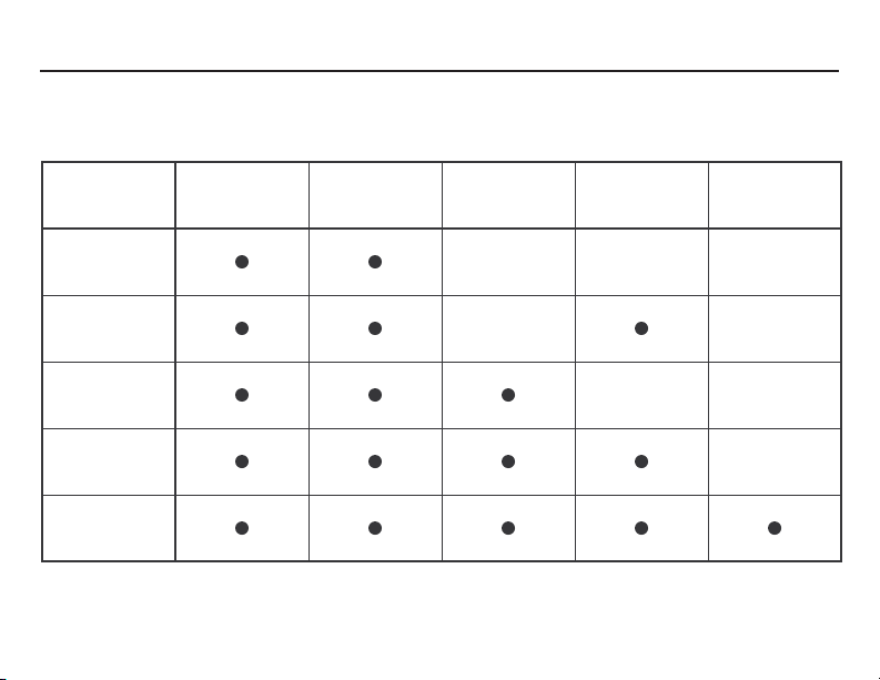
FUNCTIONAL OVERVIEW
Single Projector Models
MODEL FORWARD REVERSE FOCUS
MX20
MX30
MX40
MX40A
MX40B
NOTE: The AC Power On/Off function can be used to control Projector On/Off or Aux Power On/Off.
4
AC POWER
ON/OFF
AUX POWER
ON/OFF
Page 6
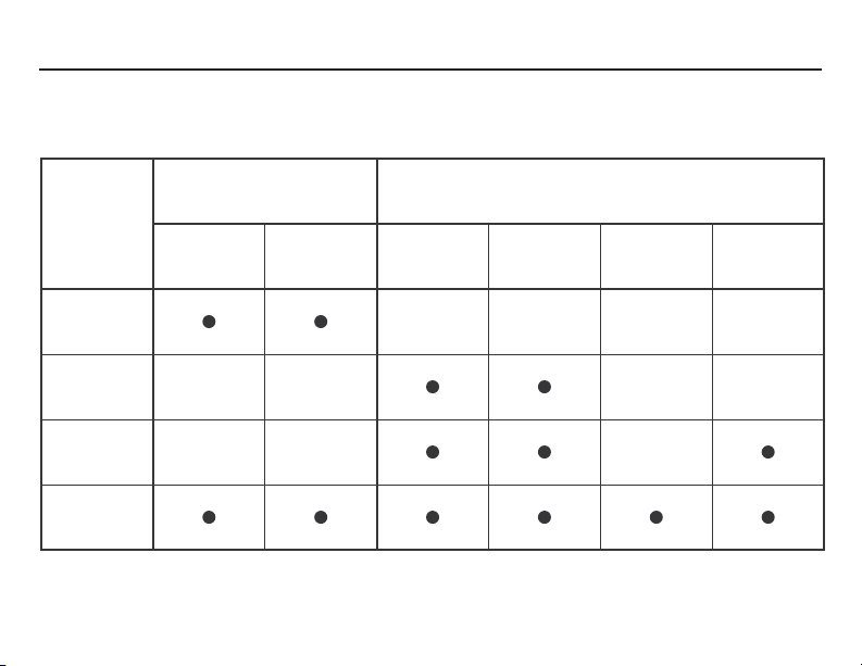
Dual Projector Models
FUNCTIONAL OVERVIEW
SIMULTANEOUS
MODEL FORWARD REVERSE FORWARD REVERSE FOCUS
MX22
MX22A
MX30A
MX120
NOTE: Dual projector controllers can also be used as single projector controllers. Also, the AC
Power On/Off function can be used to control Projector On/Off or Aux Power On/Off.
INDEPENDENT PROJECTOR ACTION
AC POWER
ON/OFF
5
Page 7
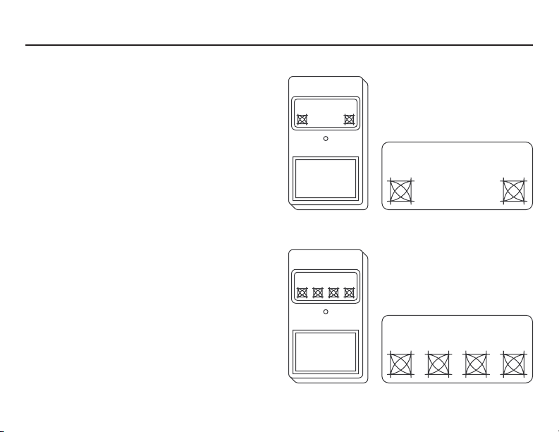
MX20, MX40
MX20 HAND CONTROLS
Press FWD and the projector advances.
Press REV and the projector reverses.
MX40 HAND CONTROLS
Press FWD and the projector advances.
Press REV and the projector reverses.
Press the left FOCUS button and the
projector focuses out.
Press the right FOCUS button and the
projector focuses in.
6
MX20
FWD REV
MX40
FWD REV
FOCUS FOCUS
Page 8
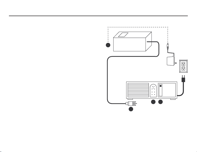
EASY INSTALLATION
1. Plug the 5-pin receiver cord (A) into the remote
receptacle on the projector (B).
2. When a Kodak® slide projector is used, the MX
Receiver will draw power from the projector. In
other cases — such as another brand of projector
or dissolve control is used — the power supply
must be connected.
3. If it is determined the power supply is needed,
plug the power cord into any standard wall outlet
(120 V) and connect the power mini plug to the
receiver power receptacle (C).
4. Extend black antenna wire vertically.
MX20, MX40
C
MX RECEIVER
A
B D
PROJECTOR
HIGH
LOW
FAN
OFF
7
Page 9
MX30, MX40A
MX30 HAND CONTROLS
Press FWD and the projector advances.
Press REV and the projector reverses.
Press both POWER buttons simultaneously to
activate AC Power On/Off.
MX40A HAND CONTROLS
Press FWD and the projector advances.
Press REV and the projector reverses.
Press the left FOCUS button and the projector
focuses out.
Press the right FOCUS button and the
projector focuses in.
Press both FOCUS buttons simultaneously to
activate AC Power On/Off.
8
MX30
POWER
FWD REV
FOCUS FOCUS
MX40A
POWER
FWD REV
FOCUS FOCUS
Page 10

MX30, MX40A
EASY INSTALLATION
1. Plug the 5-pin receiver cord (A) into the remote
receptacle on the projector (B).
2. Plug the projector AC power cord (E) into the AC
outlet on the rear of the MX Receiver Unit.
3. Plug the MX Receiver power cord (C) into a
standard wall outlet.
4. Extend black antenna wire vertically.
REMOTE
110 V AC
60 HZ
C
A
PROJECTOR
HIGH
LOW
FAN
OFF
E
B D
9
Page 11

MX22, MX22A
MX22 HAND CONTROLS
Press FWD and both projectors advance.
Press REV and both projectors reverse.
(NOTE: Rapid advance or reverse of more
than a few slides at a time is not recommended. Since individual projector speeds
may vary, rapid commands may results in
unsynchronized projectors.)
MX22A HAND CONTROLS
Press FWD for Projector 1 and this projector
advances.
Press REV for Projector 1 and this projector
reverses.
Press FWD for Projector 2 and this projector
advances.
Press REV for Projector 2 and this projector
reverses.
10
MX22
FWD REV
MX22A
PROJECTOR 1
FWD REV
2
FWD REV
Page 12
EASY INSTALLATION
1. For dual projector operation, plug the red colorcoded 5-pin control cord into the remote receptacle
on Projector 1. Plug the second unmarked control
cord into the remote receptacle on Projector 2.
2. For single projector operation, plug the red colorcoded 5-pin control cord (A) into the remote
receptacle on the slide projector (B). The FWD and
REV buttons for Projector 1 on the transmitter will
then operate the single projector.
3. When a Kodak® slide projector is used, the MX
Receiver will draw power from the projector. In
other cases — such as another brand of projector
or dissolve control is used — the power supply
must be connected.
4. If it is determined the power supply is needed,
plug the power cord into any standard wall outlet
(120 V) and connect the power mini plug to the
receiver power receptacle (C).
5. Extend black antenna wire vertically.
MX22, MX22A
C
RED
MX RECEIVER
A
B D
A
PROJECTOR 2
HIGH
LOW
FAN
OFF
PROJECTOR 1
B D
HIGH
LOW
FAN
OFF
11
Page 13

MX30A
MX30A HAND CONTROLS
Press FWD for Projector 1 and this projector
advances.
Press REV for Projector 1 and this projector
reverses.
Press FWD for Projector 2 and this projector
advances.
Press REV for Projector 2 and this projector
reverses.
Press FWD and REV for Projector 1 simultaneously for AC Power On/Off for Projector 1.
Press FWD and REV for Projector 2 simultaneously for AC Power On/Off for Projector 2.
12
MX30A
PROJECTOR 1
FWD REV
2
FWD REV
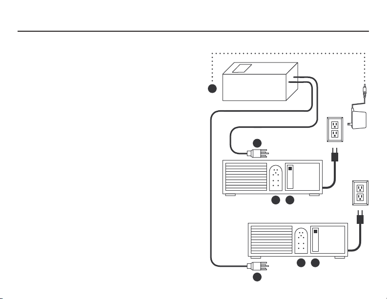
Page 14

EASY INSTALLATION
1. For dual projector operation, plug the 5-pin cord
marked “Remote 1” into the remote receptacle (B)
in Projector 1. Then plug the projector’s AC cord
(E) into the left-hand AC outlet on the rear of the
MX Receiver.
Next plug the 5-pin cord marked “Remote 2” into
the remote receptacle (B) in Projector 2. Then plug
the projector’s AC cord (E) into the right-hand AC
outlet on the rear of the MX Receiver.
2. For single projector operation, plug the 5-pin
cord (A) into the remote receptacle (B) on the
projector. Then plug the projector’s AC cord (E)
into the AC outlet on the rear of the MX Receiver.
(If using remote cord 1, use the left-hand AC
outlet. If using remote cord 2, use the righthand AC outlet as viewed from rear of unit.)
3. Plug the MX Receiver power cord (C) into a
standard wall outlet.
4. Extend black antenna wire vertically.
A
A
REMOTE21 110 V AC
110 V AC
60 HZ
PER OUTLET
C
PROJECTOR 1
HIGH
LOW
FAN
OFF
B D
60 HZ
SWITCHED
500 W MAX
PROJECTOR 2
B D
MX30A
HIGH
LOW
FAN
OFF
E
E
13
Page 15
MX40B
MX40B HAND CONTROLS
Press FWD and the projector advances.
Press REV and the projector reverses.
Press the left FOC button and the projector
focuses out.
Press the right FOC button and the projector
focuses in.
Press FWD and REV simultaneously to activate
AUX POWER On/Off.
Press both FOC buttons simultaneously to
activate Projector POWER On/Off.
14
MX40B
AUX POWER
FWD REV
POWER
FOC FOC
Page 16

MX40B
EASY INSTALLATION
1. Plug the 5-pin receiver cord (A) into the remote
receptacle on the projector (B).
2. Plug the projector AC power cord (E) into the AC
outlet on the rear of the MX Receiver.
3. If the On/Off function of the auxiliary equipment
(such as a 16mm projector or audio tape deck) is to
be controlled from the MX40B Transmitter, plug the
auxiliary equipment’s AC cord into the MX
Receiver’s right-hand AC outlet.
4. Plug the MX Receiver power cord (C) into a
standard wall outlet.
5. Extend black antenna wire vertically.
110 V AC
60 HZ
A
B D
AUXILIARY EQUIPMENT
REMOTE21
C
PROJECTOR
HIGH
LOW
FAN
OFF
E
15
Page 17

MX120
MX120 HAND CONTROLS
1. To turn the projectors on and off, simply push ON/OFF on the
transmitter. The first button press will turn the projector on, and the
second button press will turn it off.
2. A momentary press of FWD or REV will cause the tray to move in
the appropriate direction.
3. Pressing BOTH FWD and BOTH REV will move the left and right
trays simultaneously.
4. Focusing is controlled by pressing one of the FOCUS buttons
until the projected image becomes sharp. If the image goes further
out of focus, the other FOCUS button should be pressed.
LEFT SLIDES RIGHT SLIDES
FWD
REV
FOCUS
FOCUS
ON/OFF
FWD
REV
FOCUS
FOCUS
ON/OFF
16
MX120
BOTH
FWD
BOTH
REV
Page 18

EASY INSTALLATION
1. Plug the MX Receiver remote control cable (A)
marked Remote 1 into the remote receptacle (B) on
the left projector.
2. Plug the AC power cord (E) for the left slide
projector into the left-hand MX Receiver outlet.
3. Plug the MX Receiver remote control cable (A)
marked Remote 2 into the remote receptacle (B) on
the right projector.
4. Plug the AC power cord (E) for the right slide
projector into the right-hand MX Receiver outlet.
5. Plug the MX Receiver power cord (C) into a
standard wall outlet.
6. Extend black antenna wire vertically.
By following this hookup procedure, the left-hand
row of buttons on the MX120 Transmitter will
control the left-hand projector and the right-hand
row of buttons will control the right-hand projector.
A
A
REMOTE21 110 V AC
110 V AC
60 HZ
PER OUTLET
C
LEFT-HAND
PROJECTOR 1
HIGH
LOW
FAN
OFF
B D
60 HZ
SWITCHED
500 W MAX
RIGHT-HAND
PROJECTOR 2
B D
HIGH
LOW
FAN
OFF
MX120
E
E
17
Page 19

CODING INSTRUCTIONS
All AMX MX Series Slide Projector Controllers feature a
modulated RF signal for omni-directional, interferencefree operation and 150’ range, effective through walls,
glass, or screens.
Since all AMX units operate on the same frequency, DIP
switch coding is used to dedicate one transmitter (or
more) to a particular receiver(s). This coding is done by
matching the eight-position DIP switch in the transmitter
and in the receiver.
AMX has pre-set the transmitter and receiver with a
recommended code at the factory. Recoding may be
desired in order to control more than one receiver from a
single transmitter or a single receiver from more than one
transmitter. If one of these applications is desired,
recoding on the appropriate unit(s) is simple.
18
FIGURE A
Rear View of MX Transmitter
(except MX120)
9 Volt
Battery
1 2345678
O
DIP Switch
Page 20

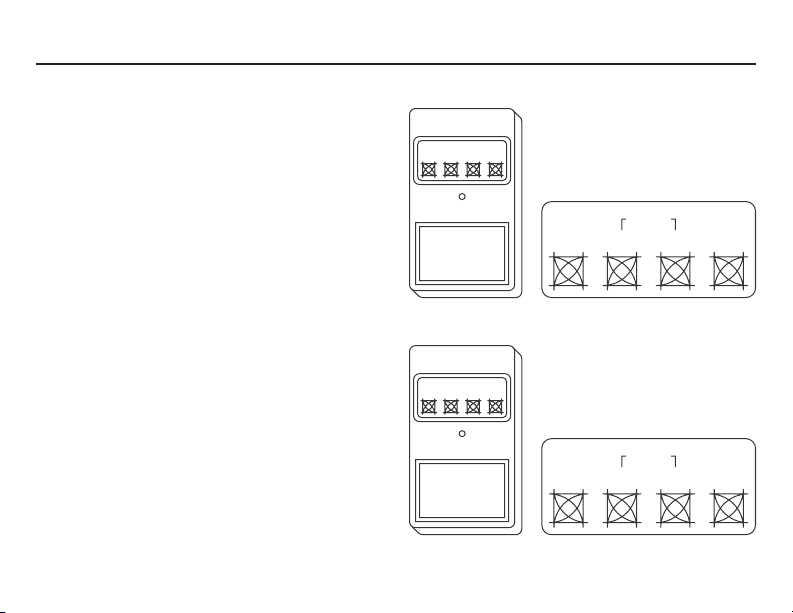
CODING INSTRUCTIONS
1. Remove the access cover on the back of the transmitter
to expose the coding DIP switch (see Figure A for all MX
Transmitters except the MX120; see Figure B for the
MX120 Transmitter).
NOTE: The coding DIP switch has eight switches
numbered 1-8. Switches 1, 2, and 3 are function designations and must not be recoded. These three switches
must remain in the “off” position. DO NOT CHANGE
SWITCHES 1, 2, and 3!
2. MX Receivers which do not have a power cord attached
(MX20, 22, 22A, and 40) have DIP switch access cut-outs
on the bottom of the receivers (see Figure C). For MX units
with attached power cords, remove the AC power cord
from the electrical outlet, unscrew the two base screws on
the MX Receiver, and gently lift the top lid off the unit.
Locate the DIP switches positioned to the right of the
large power relays (see Figure D).
(continued on next page)
FIGURE C
Rear View of MX Receiver
(MX20, 22, 22A, 40)
DIP Switch
1 2
O
19
Page 21

CODING INSTRUCTIONS
3. Using a pencil or pen, set the switches on the
transmitter coding DIP switch.
4. Now set the DIP switch in the receiver to match
the transmitter. Remember, do not change switch
positions 1, 2, or 3.
NOTE: The switches in the transmitter and
receiver units must match, but never in the “all
off” position.
20
FIGURE C
Rear View of MX Receiver
(MX20, 22, 22A, 40)
DIP Switch
1 2
O
Page 22

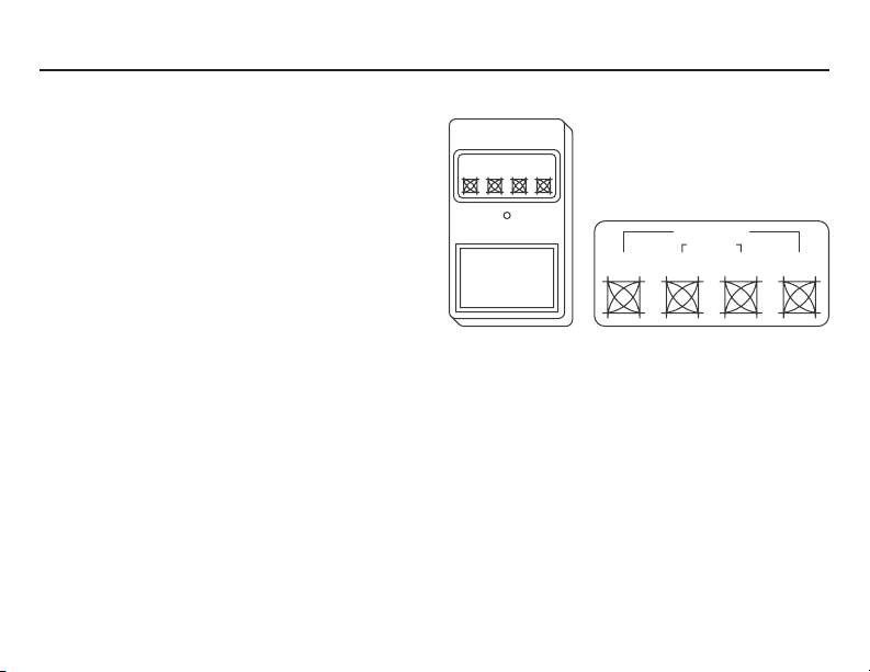
CODING INSTRUCTIONS
1 34567
FIGURE D
O
Inside Top View of MX Receiver
(MX30, 30A, 40A, 40B, 120)
Power
Transformer
BATTERY REPLACEMENT
The transmitter has a red LED indicator to monitor battery status. When a transmitter button is
pressed, the LED will glow to indicate a “good” battery. If the LED light is dim, a new battery is
needed. Simply remove the access cover on the back of the transmitter (see Figure A) and replace
the 9-volt battery. For the MX120 Transmitter, replace the two 1.5-volt, “N” size batteries (see Figure
B). Under normal usage, battery life will exceed one year. Use alkaline batteries for long battery life
and optimum performance.
DIP Switch
21
Page 23

TROUBLESHOOTING
PROBLEM: SOLUTION APPROACH:
Slide projector will not turn on when command
buttons are pressed.
Operating range is not sufficient
22
Verify that the slide projector power switch is in
the “on” position.
Check automatic “dark” shutter causing
projector to appear that it has not turned on.
Check that the projector is plugged into the MX
Receiver outlet and that the MX Receiver is
plugged into a standard wall outlet.
Remove any foil-type ID labels from MX
transmitters or receivers.
Check if the MX Receiver is resting on a metal
table or cabinet. If so, move the MX Receiver to
a wood or laminate surface. If relocation is not
practical, place non-interfering material (wood,
paper, cardboard, etc.) between the metal and
the receiver.
Check that black antenna wire is vertical.
Check the battery or batteries in the transmitter.
Page 24

TROUBLESHOOTING
PROBLEM: SOLUTION APPROACH:
No operation
No remote focus
LED on transmitter is on all the time
Check DIP switch settings — the transmitter
and receiver must match.
Ensure that the projector power switch is in
“on” position.
If a non-Kodak® projector is used, check that
the power supply is properly connected to the
MX Receiver (MX20, 22, 22A, and 40).
Check with the projector manufacturer to
ensure that the projector has a remote focus
capability.
Check DIP switch settings in the transmitter.
SWITCHES 1, 2, AND 3 ALL MUST BE IN THE
“OFF” POSITION.
23
Page 25

COMMON QUESTIONS ABOUT THE MX SERIES
Q. Do I need to point the transmitter in the
direction of the slide projector?
A. No. The transmitter emits a radio frequency
that is omni-directional. The transmitter will
work in any position.
Q. I use a rear projection screen. Will the MX
Receiver work in the projection booth?
A. Yes. The radio frequency (RF) modulation of
the MX Transmitter allows the signal to
pass through walls, screens, and glass.
Q. Will the RF signal be stronger or more
effective by pressing the buttons harder?
A. No. Only a normal touch is needed to
operate the transmitter effectively.
24
Q. I dropped my transmitter or lost it. Can I
order a replacement transmitter only?
A. Yes. AMX sells all models of MX transmit-
ters by themselves and can generally ship
the same day in an emergency. Ask your
audiovisual or photography dealer for
pricing and details.
Q. We need to operate two MX units in
adjacent rooms. Will they interfere with
each other?
A. No. As long as the DIP switch settings are
different for each room, the MX units will
not interfere.
Page 26

MX SERIES LIMITED WARRANTY
All MX systems are warranted against defects in materials and workmanship for one year from date
of purchase.
This warranty extends only to units purchased directly from AMX. Consumers should inquire from
their selling dealer as to the nature and extent of the dealer’s warranty, if any.
There are no obligations or liabilities on the part of AMX Corporation for consequential damages
arising out of or in conjunction with the use or performance of these products or other indirect
damages with respect to loss of profit, revenue, or cost of removal and/or replacement. All implied
warranties, including implied warranties for merchantability and/or fitness, are limited in duration to
one year from date of purchase.
This AMX Warranty is in lieu of all other warranties, expressed or implied.
© 1992 AMX Corporation
11995 Forestgate Drive
Dallas, Texas 75243
AMX reserves the right to alter specifications without notice at any time.
25
Page 27

11995 Forestgate Drive • Dallas, Texas 75243
800/222–0193 • 972/644–3048 • FAX 972/907–2053TRN–022 11/92
 Loading...