

Page 1
Operation/Reference Guide
MVP-9000i
9" Modero® ViewPoint
®
Touch Panel with Intercom
Touch Panels
Last Revised: 5/18/2011
Page 2

AMX Limited Warranty and Disclaimer
This Limited Warranty and Disclaimer extends only to products purchased directly from AMX or an AMX Authorized Partner which
include AMX Dealers, Distributors, VIP’s or other AMX authorized entity.
AMX warrants its products to be free of defects in material and workmanship under normal use for three (3) years from the date of
purchase, with the following exceptions:
• Electroluminescent and LCD Control Panels are warranted for three (3) years, except for the display and touch overlay components are warranted for a period of one (1) year.
• Disk drive mechanisms, pan/tilt heads, power supplies, and MX Series products are warranted for a period of one (1) year.
• AMX lighting products are guaranteed to switch on and off any load that is properly connected to our lighting products, as long
as the AMX lighting products are under warranty. AMX also guarantees the control of dimmable loads that are properly connected to our lighting products. The dimming performance or quality there of is not guaranteed, impart due to the random combinations of dimmers, lamps and ballasts or transformers.
• AMX software is warranted for a period of ninety (90) days.
• Batteries and incandescent lamps are not covered under the warranty.
• AMX AutoPatch Epica, Modula, Modula Series4, Modula CatPro Series and 8Y-3000 product models will be free of defects in
materials and manufacture at the time of sale and will remain in good working order for a period of three (3) years following the
date of the original sales invoice from AMX. The three-year warranty period will be extended to the life of the product (Limited
Lifetime Warranty) if the warranty card is filled out by the dealer and/or end user and returned to AMX so that AMX receives it
within thirty (30) days of the installation of equipment but no later than six (6) months from original AMX sales invoice date. The
life of the product extends until five (5) years after AMX ceases manufacturing the product model. The Limited Lifetime Warranty
applies to products in their original installation only. If a product is moved to a different installation, the Limited Lifetime Warranty
will no longer apply, and the product warranty will instead be the three (3) year Limited Warranty.
All products returned to AMX require a Return Material Authorization (RMA) number. The RMA number is obtained from the AMX
RMA Department. The RMA number must be clearly marked on the outside of each box. The RMA is valid for a 30-day period. After
the 30-day period the RMA will be cancelled. Any shipments received not consistent with the RMA, or after the RMA is cancelled, will
be refused. AMX is not responsible for products returned without a valid RMA number.
AMX is not liable for any damages caused by its products or for the failure of its products to perform. This includes any lost profits, lost
savings, incidental damages, or consequential damages. AMX is not liable for any claim made by a third party or by an AMX Authorized Partner for a third party.
This Limited Warranty does not apply to (a) any AMX product that has been modified, altered or repaired by an unauthorized agent or
improperly transported, stored, installed, used, or maintained; (b) damage caused by acts of nature, including flood, erosion, or earthquake; (c) damage caused by a sustained low or high voltage situation or by a low or high voltage disturbance, including brownouts,
sags, spikes, or power outages; or (d) damage caused by war, vandalism, theft, depletion, or obsolescence.
This limitation of liability applies whether damages are sought, or a claim is made, under this warranty or as a tort claim (including
negligence and strict product liability), a contract claim, or any other claim. This limitation of liability cannot be waived or amended by
any person. This limitation of liability will be effective even if AMX or an authorized representative of AMX has been advised of the
possibility of any such damages. This limitation of liability, however, will not apply to claims for personal injury.
Some states do not allow a limitation of how long an implied warranty last. Some states do not allow the limitation or exclusion of incidental or consequential damages for consumer products. In such states, the limitation or exclusion of the Limited Warranty may not
apply. This Limited Warranty gives the owner specific legal rights. The owner may also have other rights that vary from state to state.
The owner is advised to consult applicable state laws for full determination of rights.
EXCEPT AS EXPRESSLY SET FORTH IN THIS WARRANTY, AMX MAKES NO OTHER WARRANTIES, EXPRESSED OR
IMPLIED, INCLUDING ANY IMPLIED WARRANTIES OF MERCHANTABILITY OR FITNESS FOR A PARTICULAR PURPOSE. AMX
EXPRESSLY DISCLAIMS ALL WARRANTIES NOT STATED IN THIS LIMITED WARRANTY. ANY IMPLIED WARRANTIES THAT
MAY BE IMPOSED BY LAW ARE LIMITED TO THE TERMS OF THIS LIMITED WARRANTY. EXCEPT AS OTHERWISE LIMITED
BY APPLICABLE LAW, AMX RESERVES THE RIGHT TO MODIFY OR DISCONTINUE DESIGNS, SPECIFICATIONS, WARRANTIES, PRICES, AND POLICIES WITHOUT NOTICE.
Page 3

AMX Software License and Warranty Agreement
• LICENSE GRANT. AMX grants to Licensee the non-exclusive right to use the AMX Software in the manner described in this
License. The AMX Software is licensed, not sold. This license does not grant Licensee the right to create derivative works of the
AMX Software. The AMX Software consists of generally available programming and development software, product documentation, sample applications, tools and utilities, and miscellaneous technical information. Please refer to the README.TXT file on
the compact disc or download for further information regarding the components of the AMX Software. The AMX Software is subject to restrictions on distribution described in this License Agreement. AMX Dealer, Distributor, VIP or other AMX authorized
entity shall not, and shall not permit any other person to, disclose, display, loan, publish, transfer (whether by sale, assignment,
exchange, gift, operation of law or otherwise), license, sublicense, copy, or otherwise disseminate the AMX Software. Licensee
may not reverse engineer, decompile, or disassemble the AMX Software.
• ACKNOWLEDGEMENT. You hereby acknowledge that you are an authorized AMX dealer, distributor, VIP or other AMX authorized entity in good standing and have the right to enter into and be bound by the terms of this Agreement.
• INTELLECTUAL PROPERTY. The AMX Software is owned by AMX and is protected by United States copyright laws, patent
laws, international treaty provisions, and/or state of Texas trade secret laws. Licensee may make copies of the AMX Software
solely for backup or archival purposes. Licensee may not copy the written materials accompanying the AMX Software.
• TERMINATION. AMX RESERVES THE RIGHT, IN ITS SOLE DISCRETION, TO TERMINATE THIS LICENSE FOR ANY REASON UPON WRITTEN NOTICE TO LICENSEE. In the event that AMX terminates this License, the Licensee shall return or
destroy all originals and copies of the AMX Software to AMX and certify in writing that all originals and copies have been
returned or destroyed.
• PRE-RELEASE CODE. Portions of the AMX Software may, from time to time, as identified in the AMX Software, include PRERELEASE CODE and such code may not be at the level of performance, compatibility and functionality of the GA code. The
PRE-RELEASE CODE may not operate correctly and may be substantially modified prior to final release or certain features may
not be generally released. AMX is not obligated to make or support any PRE-RELEASE CODE. ALL PRE-RELEASE CODE IS
PROVIDED "AS IS" WITH NO WARRANTIES.
• LIMITED WARRANTY. AMX warrants that the AMX Software (other than pre-release code) will perform substantially in accordance with the accompanying written materials for a period of ninety (90) days from the date of receipt. AMX DISCLAIMS ALL
OTHER WARRANTIES, EITHER EXPRESS OR IMPLIED, INCLUDING, BUT NOT LIMITED TO IMPLIED WARRANTIES OF
MERCHANTABILITY AND FITNESS FOR A PARTICULAR PURPOSE, WITH REGARD TO THE AMX SOFTWARE. THIS LIMITED WARRANTY GIVES LICENSEE SPECIFIC LEGAL RIGHTS. Any supplements or updates to the AMX SOFTWARE,
including without limitation, any (if any) service packs or hot fixes provided to Licensee after the expiration of the ninety (90) day
Limited Warranty period are not covered by any warranty or condition, express, implied or statutory.
• LICENSEE REMEDIES. AMX's entire liability and Licensee's exclusive remedy shall be repair or replacement of the AMX Software that does not meet AMX's Limited Warranty and which is returned to AMX in accordance with AMX's current return policy.
This Limited Warranty is void if failure of the AMX Software has resulted from accident, abuse, or misapplication. Any replacement AMX Software will be warranted for the remainder of the original warranty period or thirty (30) days, whichever is longer.
Outside the United States, these remedies may not available. NO LIABILITY FOR CONSEQUENTIAL DAMAGES. IN NO
EVENT SHALL AMX BE LIABLE FOR ANY DAMAGES WHATSOEVER (INCLUDING, WITHOUT LIMITATION, DAMAGES
FOR LOSS OF BUSINESS PROFITS, BUSINESS INTERRUPTION, LOSS OF BUSINESS INFORMATION, OR ANY OTHER
PECUNIARY LOSS) ARISING OUT OF THE USE OF OR INABILITY TO USE THIS AMX SOFTWARE, EVEN IF AMX HAS
BEEN ADVISED OF THE POSSIBILITY OF SUCH DAMAGES. BECAUSE SOME STATES/COUNTRIES DO NOT ALLOW
THE EXCLUSION OR LIMITATION OF LIABILITY FOR CONSEQUENTIAL OR INCIDENTAL DAMAGES, THE ABOVE LIMITATION MAY NOT APPLY TO LICENSEE.
• U.S. GOVERNMENT RESTRICTED RIGHTS. The AMX Software is provided with RESTRICTED RIGHTS. Use, duplication, or
disclosure by the Government is subject to restrictions as set forth in subparagraph ©(1)(ii) of The Rights in Technical Data and
Computer Software clause at DFARS 252.227-7013 or subparagraphs ©(1) and (2) of the Commercial Computer Software
Restricted Rights at 48 CFR 52.227-19, as applicable.
• SOFTWARE AND OTHER MATERIALS FROM AMX.COM MAY BE SUBJECT TO EXPORT CONTROL. The United States
Export Control laws prohibit the export of certain technical data and software to certain territories. No software from this Site may
be downloaded or exported (i) into (or to a national or resident of) Cuba, Iraq, Libya, North Korea, Iran, Syria, or any other country to which the United States has embargoed goods; or (ii) anyone on the United States Treasury Department's list of Specially
Designated Nationals or the U.S. Commerce Department's Table of Deny Orders. AMX does not authorize the downloading or
exporting of any software or technical data from this site to any jurisdiction prohibited by the United States Export Laws.
This Agreement replaces and supersedes all previous AMX Software License Agreements and is governed by the laws of
the State of Texas, and all disputes will be resolved in the courts in Collin County, Texas, USA. For any questions concerning this Agreement, or to contact AMX for any reason, please write: AMX License and Warranty Department, 3000 Research
Drive, Richardson, TX 75082.
Page 4
FCC and IC Information
This device complies with Part 15 of the FCC Rules and Industry Canada license-exempt RSS standard(s). Operation
is subject to the following two conditions: (1) this device may not cause harmful interference, and (2) this device must
accept any interference received; including interference that may cause undesired operation.
Modifications to this product, unless expressly approved by AMX, could void the user’s authority to operate the
equipment.
Cet appareil est conforme avec Industrie Canada RSS standard exempts de licence (s). Son utilisation est soumise à
Les deux conditions suivantes: (1) cet appareil ne peut pas provoquer d'interférences et (2) cet appareil doit accepter
Toute interférence , y compris les interférences qui peuvent causer un mauvais fonctionnement du dispositif.
This device complies with Health Canada's Safety Code 6 / IC RSS-210. The installer of this device should ensure that
RF radiation is not emitted in excess of the Health Canada's requirement. Information can be obtained at:
http://www.hc-sc.gc.ca/ewh-semt/pubs/radiation/radio_guidelignes_direct-eng.php
Cet appareil est conforme avec Santé Canada Code de sécurité 6 / IC RSS-210. Le programme d'installation de cet
appareil doit s'assurer que les rayonnements RF n'est pas émis au-delà de l'exigence de Santé Canada. Les informations peuvent être obtenues: http://www.hc-sc.gc.ca/ewhsemt/ pubs/radiation/radio_guide-lignes_direct-eng.php
Federal Communications Commission (FCC)
Statement
This equipment has been tested and found to comply with the limits for a Class B digital device, pursuant to Part 15 of
the FCC rules. These limits are designed to provide reasonable protection against harmful interference in a residential
installation. This equipment generates, uses and can radiate radio frequency energy, and, if not installed and used in
accordance with the instructions, may cause harmful interference to radio communications. However, there is no
guarantee that interference will not occur in a particular installation. If this equipment does cause harmful
interference to radio or television reception, which can be determined by turning the equipment off and on, the user is
encouraged to try to correct the interference by one or more of the following measures:
• Reorient or relocate the receiving antenna.
• Increase the separation between the equipment and receiver.
• Connect the equipment into an outlet on a circuit different from that to which the receiver is connected.
• Consult the dealer or an experienced radio/TV technician for help.
FCC RF Radiation Exposure Statement
This product has been evaluated and found to comply with the limits established by the FCC, Industry Canada and
other international standards for radio frequency exposure when used as described in this manual. The use of
accessories not described may not ensure compliance with these limits.
Indoor Use
This device is intended for indoor use only. WiFi operation in the 5150-5250 MHz range is only for indoor usage to
reduce potential for harmful interference to co-channel mobile satellite systems.
Dans la gamme de fréquences 5150 - 5250MHz, cet appareil est exclusivement destiné à un usage en intérieur afin de
réduire les risques potentiels d'interférences avec les systèmes de communications satellites partageant les mêmes
canaux.
Page 5

1
MVP-9000i Modero® Wireless Touch Panel with Intercom
Table of Contents
Introduction ........................................................................................................1
Overview .................................................................................................................. 1
Common Application....................................................................................................... 1
Features .......................................................................................................................... 1
Memory .................................................................................................................... 4
Connector Locations................................................................................................. 4
Basic Operation ........................................................................................................ 4
Powering on the MVP-9000i..................................................................................... 5
Intercom Microphone ............................................................................................... 5
Stylus........................................................................................................................ 5
Kick Stand................................................. ..... ........................................................... 5
Audio/Video Capabilities.......................................................................................... 5
Power Management....................................... ........................................................... 5
Cleaning the Touch Overlay and Case ...................................................................... 6
Picture View.............................................................................................................. 6
Preview Mode and Normal Mode ................................................................................... 7
Picture View Send Command.......................................................................................... 7
Seamless Wireless to Wired Swap ............................................................................ 8
Accessories .......................................................................................................11
Table Docking Station............................................................................................. 11
Powering the MVP-TDS-9.............................................................................................. 12
Recharging.................................................................................................................... 13
Using the USB ports... ... .......................................... ... ... .... ... ... ... .... ............................... 13
Undocking the Touch Panel............................................................................ ... ... ......... 13
Cleaning the MVP-TDS-9............................................................................................... 13
Wall Docking Station .............................................................................................. 14
Unlocking the Touch Panel ..................................................................................... 15
Recharging.............................................................................................................. 16
Installing the MVP-WDS-9....................................................................................... 17
Installing the Wall Docking Station and Plastic Back Box.............................................. 17
Installing the Optional Metal Rough-In Box............................................................ 20
Pre-Wall Installation of the CB-MVP-WDS9................................................................... 20
Other MVP-WDS-9 installations .................................................................................... 21
Undocking from the MVP-TDS-9 or MVP-WDS-9.................................................... 22
Configuring Communication .............................................................................25
Overview ................................................................................................................ 25
Page 6

2
MVP-9000i Modero® Wireless Touch Panel with Intercom
IR Communication................................................................................................... 26
Modero Setup and System Settings ....................................................................... 26
Accessing the Setup and Protected Setup Pages.......................................................... 26
Setting the Panel’s Device Number............................................................................... 27
Wireless Settings - Wireless Access Overview ........................................................ 28
DHCP............................................................................................................................. 28
Configuring Wireless Network Access .................................................................... 28
Step 1: Configure the Device’s WiFi Settings ......................................................... 28
Wireless communication using a DHCP Address ........................................................... 28
Wireless Communication Using a Static IP Address....................................................... 29
Using the Wireless Site Survey Tool .............................................................................. 30
Step 2: Configure the Card’s Wireless Security Settings ........................................ 32
Configuring the Device’s Wireless Card for Secured access to a WPA-PSK-Secured AP 32
Step 3: Choose a Master Connection Mode ........................................................... 33
Ethernet Over USB ................................................................................................. 34
Touch Panel Setup......................................................................................................... 34
Configure a Virtual NetLinx Master using NetLinx Studio............................................. 37
Ethernet ........................................................................................................................ 38
Master Connection to a Virtual Master via Ethernet ..................................................... 39
Using G4 Web Control to Interact with a G4 Panel ................................................ 42
Using the NetLinx Master To Control the G4 Panel.............................................. .. 43
Setup Pages ......................................................................................................47
Overview ................................................................................................................ 47
Accessing the Setup pages..................................................................................... 47
Landscape and Portrait Mode Setup Pages............................................................ 47
Setup Page ............................................................................................................. 48
Navigation Buttons................. ... .......................................... ... ... .................................... 49
Display Page........................................................................................................... 50
Audio Page............................................................................................................. 51
WAV files - Supported Sample Rates ............................................................................ 52
Power Management Page....................................................................................... 53
Date/Time Page...................................................................................................... 55
Panel Information Page........................................................................................... 57
Panel Information Page - Info........................................................................................ 57
Panel Information Page - Config.................................................................................... 58
Panel Information Page - File ........................................................................................ 59
Panel Information Page - Project................................................................................... 60
Protected Setup Pages .....................................................................................63
Zero-Configuration Networking.............................................................................. 64
Page 7

3
MVP-9000i Modero® Wireless Touch Panel with Intercom
Zero-Configuration Client ............................................................................................. 64
Accessing the MVP-9000i via Zero-Configuration......................................................... 65
Enabling and Disabling Zero-Configuration Capability ................................................. 65
System & Panel Options page ................................................................................ 66
Function Show Example................................................................................................ 67
Security Settings ........................... ... .... ... ... ... .......................................... .... ... ............... 68
Installing Firmware. .... .......................................... ... ... .......................................... .... ... .. 69
System Settings Page ............................................................................................. 70
System Settings - Master ..................................... ... .......................................... ... .... ..... 70
System Settings - Wired................................ ... .... .......................................... ... ... ......... 72
System Settings - WiFi ..................................... ........................................... ... ... ............ 73
Security Modes....................................................................................................... 76
Open............................................................................................................................. 76
WEP .............................................................................................................................. 77
WPA-PSK....................................................................................................................... 79
EAP Security & Server Certificates - Overview ....................................................... 81
EAP-LEAP...................................................................................................................... 82
EAP-FAST...................................................................................................................... 84
EAP-PEAP...................................................................................................................... 86
EAP-TTLS....................................................................................................................... 88
EAP-TLS......................................................................................................................... 90
Client Certificate Configuration .................................................................................... 92
System Settings - USB................................ ... ... .... ... .......................................... ... .... ..... 93
Calibrate Page........................................................................................................ 94
G4 Web Control Settings Page............................................................................... 95
Passwords............................................................................................................... 97
Panel Logs Page ..................................................................................................... 99
Cache Settings Page............................................................................................. 100
Panel Statistics Page............................................................................................. 102
Panel Statistics - ICSP.................................................................................................. 102
Panel Statistics - Blinks Tab......................................................................................... 103
Panel Statistics - IP Tab ............................................................................................... 104
Panel Statistics - Wireless Tab..................................................................................... 104
Connection Utility Page .............................................................................................. 105
SIP Settings Page.................................................................................................. 106
Upgrading Firmware ......................................................................................109
Overview .............................................................................................................. 109
Upgrading Firmware via USB stick or MicroSD card............................................. 109
Upgrading from Previous Firmware...................................................................... 112
Page 8

4
MVP-9000i Modero® Wireless Touch Panel with Intercom
Upgrading Firmware Via NetLinx Studio .............................................................. 113
Step 3: Confirm and Upgrade the firmware via the USB port..................................... 114
A Special Note for Network Interface Connections.............................................. 118
Reverting the MVP-9000i to Factory Default Firmware........................................ 121
Programming ..................................................................................................125
Overview .............................................................................................................. 125
Animated Transitions............................................................................................ 125
^AFP 126
Touch Gesture Recognition................................................................................... 127
Gesture Velocity.......................................................................................................... 127
Gesture Prioritization .................................................................................................. 127
Gesture VNC/Mouse Support...................................................................................... 128
Gesture Custom Event ................................................................................................ 128
Enabling or Disabling the Gesture Custom Event ....................................................... 128
^GCE 128
.............................................................................................................................. 128
Page Commands................................... ..... ..... ..... ..... .... ........................................ 129
@APG...................................................................................................................................... 129
@CPG...................................................................................................................................... 129
@DPG...................................................................................................................................... 129
@PDR...................................................................................................................................... 129
@PHE ...................................................................................................................................... 129
@PHP ...................................................................................................................................... 130
@PHT ...................................................................................................................................... 130
@PPA ...................................................................................................................................... 130
@PPF....................................................................................................................................... 130
@PPG...................................................................................................................................... 131
@PPK ...................................................................................................................................... 131
@PPM...................................................................................................................................... 131
@PPN...................................................................................................................................... 131
@PPT....................................................................................................................................... 132
@PPX ...................................................................................................................................... 132
@PSE....................................................................................................................................... 132
@PSP....................................................................................................................................... 132
@PST....................................................................................................................................... 132
PAGE ...................................................................................................................................... 132
PPOF....................................................................................................................................... 133
PPOG...................................................................................................................................... 133
PPON...................................................................................................................................... 133
Programming Numbers......................................................................................... 134
RGB Triplets and Names For Basic 88 Colors ............................................................. 134
Font Styles And Id Numbers ....................................................................................... 136
Border Styles And Programming Numbers ................................................................. 136
"^" Button Commands ......................................................................................... 138
Page 9

5
MVP-9000i Modero® Wireless Touch Panel with Intercom
^ANI........................................................................................................................................ 138
^APF ....................................................................................................................................... 138
^BAT ....................................................................................................................................... 139
^BAU....................................................................................................................................... 139
^BCB....................................................................................................................................... 139
^BCF ....................................................................................................................................... 140
^BCT ....................................................................................................................................... 140
^BDO ...................................................................................................................................... 140
^BFB........................................................................................................................................ 141
^BIM........................................................................................................................................ 141
^BLN ....................................................................................................................................... 141
^BMC...................................................................................................................................... 142
^BMF....................................................................................................................................... 143
^BMI........................................................................................................................................ 144
^BML....................................................................................................................................... 144
^BMP ...................................................................................................................................... 145
^BNC....................................................................................................................................... 145
^BNN ...................................................................................................................................... 145
^BNT....................................................................................................................................... 145
^BOP....................................................................................................................................... 145
^BOR....................................................................................................................................... 146
^BOS....................................................................................................................................... 146
^BPP........................................................................................................................................ 146
^BRD....................................................................................................................................... 146
^BSF........................................................................................................................................ 147
^BSM....................................................................................................................................... 147
^BSO....................................................................................................................................... 147
^BVL........................................................................................................................................ 147
^BVN....................................................................................................................................... 147
^BVP ....................................................................................................................................... 148
^BVT ....................................................................................................................................... 148
^BWW..................................................................................................................................... 148
^CPF........................................................................................................................................ 148
^DLD....................................................................................................................................... 148
^DPF ....................................................................................................................................... 149
^ENA....................................................................................................................................... 149
^FON ...................................................................................................................................... 149
^GDI........................................................................................................................................ 150
^GIV........................................................................................................................................ 150
^GLH....................................................................................................................................... 150
^GLL........................................................................................................................................ 150
^GRD....................................................................................................................................... 150
^GRU....................................................................................................................................... 151
^GSC....................................................................................................................................... 151
^GSN....................................................................................................................................... 151
^ICO........................................................................................................................................ 151
^IRM........................................................................................................................................ 152
^JSB........................................................................................................................................ 152
^JSI ......................................................................................................................................... 152
^JST ........................................................................................................................................ 153
Page 10

6
MVP-9000i Modero® Wireless Touch Panel with Intercom
^MBT...................................................................................................................................... 153
^MDC ..................................................................................................................................... 153
^PIC........................................................................................................................................ 153
^SHO...................................................................................................................................... 153
^TEC....................................................................................................................................... 154
^TEF ....................................................................................................................................... 154
^TXT....................................................................................................................................... 154
^UNI ....................................................................................................................................... 155
^WLD...................................................................................................................................... 155
Miscellaneous MVP Strings.......................................................................................... 156
undock-<user>........................................................................................................................ 156
UNDOCKED............................................................................................................................ 156
SWAP...................................................................................................................................... 156
dock........................................................................................................................................ 156
MVP Panel Lock Passcode Commands ........................................................................ 157
^LPC ....................................................................................................................................... 157
^LPR ....................................................................................................................................... 157
^LPS........................................................................................................................................ 157
Text Effects Names............................................................................................... 158
Button Query Commands ..................................................................................... 158
?BCB....................................................................................................................................... 159
?BCF ....................................................................................................................................... 160
?BCT ....................................................................................................................................... 160
?BMP ...................................................................................................................................... 161
?BOP....................................................................................................................................... 161
?BRD....................................................................................................................................... 162
?BWW..................................................................................................................................... 162
?FON ...................................................................................................................................... 163
?ICO........................................................................................................................................ 163
?JSB........................................................................................................................................ 164
?JSI ......................................................................................................................................... 164
?JST ........................................................................................................................................ 165
?TEC........................................................................................................................................ 165
?TEF........................................................................................................................................ 166
?TXT........................................................................................................................................ 166
Panel Runtime Operations .................................................................................... 167
ABEEP..................................................................................................................................... 167
ADBEEP.................................................................................................................................. 167
@AKB...................................................................................................................................... 167
AKEYB .................................................................................................................................... 167
AKEYP..................................................................................................................................... 167
AKEYR..................................................................................................................................... 167
@AKP...................................................................................................................................... 168
@AKR...................................................................................................................................... 168
BEEP ....................................................................................................................................... 168
BRIT ........................................................................................................................................ 168
@BRT....................................................................................................................................... 168
DBEEP..................................................................................................................................... 168
Page 11

7
MVP-9000i Modero® Wireless Touch Panel with Intercom
@EKP....................................................................................................................................... 168
PKEYP ..................................................................................................................................... 169
@PKP....................................................................................................................................... 169
SETUP...................................................................................................................................... 169
SHUTDOWN............................................................................................................................ 169
SLEEP...................................................................................................................................... 169
@SOU...................................................................................................................................... 169
@TKP....................................................................................................................................... 170
TPAGEON ............................................................................................................................... 170
TPAGEOFF .............................................................................................................................. 170
@VKB....................................................................................................................................... 170
WAKE...................................................................................................................................... 170
Input Commands................................................................................................... 171
^CAL ....................................................................................................................................... 171
^KPS........................................................................................................................................ 171
^VKS ....................................................................................................................................... 171
Embedded codes.................................................................................................. 172
Panel Setup Commands........................................................................................ 173
@PWD ..................................................................................................................................... 173
^PWD...................................................................................................................................... 173
Dynamic Image Commands................................................................................... 174
^BBR ....................................................................................................................................... 174
^RAF ....................................................................................................................................... 174
^RFR 174
^RAF, ^RMF - Embedded Codes ................................................................................ 175
^RMF 175
^RSR 175
Escape Sequences....................................................................................................... 176
$DV ......................................................................................................................................... 176
$SY.......................................................................................................................................... 176
$IP........................................................................................................................................... 176
$HN......................................................................................................................................... 176
$MC......................................................................................................................................... 176
$ID........................................................................................................................................... 176
$PX.......................................................................................................................................... 176
$PY.......................................................................................................................................... 176
$ST.......................................................................................................................................... 176
$AC ......................................................................................................................................... 176
$AP.......................................................................................................................................... 176
$CC ......................................................................................................................................... 176
$CP.......................................................................................................................................... 176
$LC.......................................................................................................................................... 176
$LP .......................................................................................................................................... 176
$BX.......................................................................................................................................... 176
$BY.......................................................................................................................................... 176
$BN......................................................................................................................................... 176
Intercom Commands............................................................................................. 177
^MODEL?................................................................................................................................ 177
Page 12

8
MVP-9000i Modero® Wireless Touch Panel with Intercom
^ICS-....................................................................................................................................... 177
^ICE'....................................................................................................................................... 177
^ICM-TALK ............................................................................................................................. 178
^ICM-LISTEN........................................................................................................................... 178
^ICM-MICLEVEL...................................................................................................................... 178
^ICM-MUTEMIC...................................................................................................................... 178
^ICM-SPEAKERLEVEL............................................................................................................. 178
SIP Commands...................................................................................................... 179
^PHN-AUTOANSWER............................................................................................................. 179
^PHN-CALL............................................................................................................................. 179
^PHN-DECLINE....................................................................................................................... 179
^PHN-INCOMING................................................................................................................... 179
^PHN-LINESTATE ................................................................................................................... 179
^PHN-ANSWER ...................................................................................................................... 180
^PHN-AUTOANSWER............................................................................................................. 180
^PHN-MSGWAITING .............................................................................................................. 180
^PHN-PRIVACY....................................................................................................................... 180
^PHN-REDIAL......................................................................................................................... 180
^PHN-TRANSFERRED............................................................................................................. 180
?PHN-AUTOANSWER ............................................................................................................. 181
^PHN-CALL............................................................................................................................. 181
^PHN-DTMF ........................................................................................................................... 181
^PHN-HANGUP ...................................................................................................................... 181
^PHN-HOLD ........................................................................................................................... 181
?PHN-LINESTATE.................................................................................................................... 181
^PHN-PRIVACY....................................................................................................................... 181
?PHN-PRIVACY ....................................................................................................................... 181
^PHN-REDIAL......................................................................................................................... 181
^PHN-SETUP-DOMAIN........................................................................................................... 182
^PHN-SETUP-ENABLE ............................................................................................................ 182
^PHN-SETUP-PASSWORD ...................................................................................................... 182
^PHN-SETUP-PORT................................................................................................................. 182
^PHN-SETUP-PROXYADDR .................................................................................................... 182
^PHN-SETUP-STUNADDR....................................................................................................... 182
^PHN-SETUP-USERNAME....................................................................................................... 182
^PHN-TRANSFER.................................................................................................................... 182
Battery Life and Replacement ........................................................................183
Overview .............................................................................................................. 183
IMPORTANT NOTES!............................................................................................ 184
Power Management.................... ..... ................................................................ ..... 185
Proper Battery Maintenance............ ................................................................ ..... 185
Battery Replacement ............................................................................................ 186
READ THESE INSTRUCTIONS FIRST!......... ... .......................................... .... ... ... ... ........ 186
Replacing the Battery ........................................................................................... 186
Remove the old battery .............................................................................................. 188
Installing the new battery............................................................................................ 188
Page 13

9
MVP-9000i Modero® Wireless Touch Panel with Intercom
Reconnecting the battery to the device...................................................................... 188
Appendix A: Text Formatting .........................................................................191
Text Formatting Codes for Bargraphs/Joysticks................................................... 191
Text Area Input Masking....................................................................................... 192
Input mask character types ......................................................................................... 192
Input Mask Ranges...................................................................................................... 193
Input mask next field characters ................................................................................. 193
Input mask operations................................................................................................. 193
Input mask literals....................................................................................................... 193
Input mask output examples....................................................................................... 194
URL Resources .......................................... ..... .... ..... .............................................. 194
Special Escape Sequences........................................................................................... 194
Appendix B: Wireless Technology ..................................................................197
Overview of Wireless Technology......................................................................... 197
Terminology.......................................................................................................... 198
802.1x......................................................................................................................... 198
AES ............................................................................................................................. 198
CERTIFICATES (CA) ..................................................................................................... 198
MIC.............................................................................................................................. 198
TKIP............................................................................................................................. 198
WEP ............................................................................................................................ 198
WPA............................................................................................................................ 198
WPA2.......................................................................................................................... 199
EAP Authentication............................................................................................... 200
EAP Characteristics ..................................................................................................... 200
EAP Communication Overview.................................................................................... 201
Configuring Modero Firmware via the USB Port .................................................. 202
Step 1: Configure The Panel For a USB Connection Type........................................... 202
Step 2: Prepare NetLinx Studio For Communication Via the USB Port....................... 202
AMX Certificate Upload Utility ............................................................................. 203
Uploading a Certificate File.................................................................................. 203
Appendix C: Troubleshooting ........................................................................205
Overview .............................................................................................................. 205
Panel Doesn’t Respond To Touches ............................................................................ 205
Battery Will Not Hold Or Take A Charge .................................................................... 205
MVP-9000i Isn’t Appearing In The Online Tree Tab.................................................... 205
MVP Can’t Obtain a DHCP Address............................................................................ 206
My AP Doesn’t Seem To Be Working.......................................................................... 206
NetLinx Studio Only Detects One Of My Connected Masters .................................... 206
Page 14

10
MVP-9000i Modero® Wireless Touch Panel with Intercom
Can’t Connect To a NetLinx Master ............................................................................ 206
Only One Modero Panel In My System Shows Up....................................................... 206
Panel Behaves Strangely After Downloading A Panel File Or Firmware ..................... 207
Page 15
1
MVP-9000i Modero® Wireless Touch Panel with Intercom
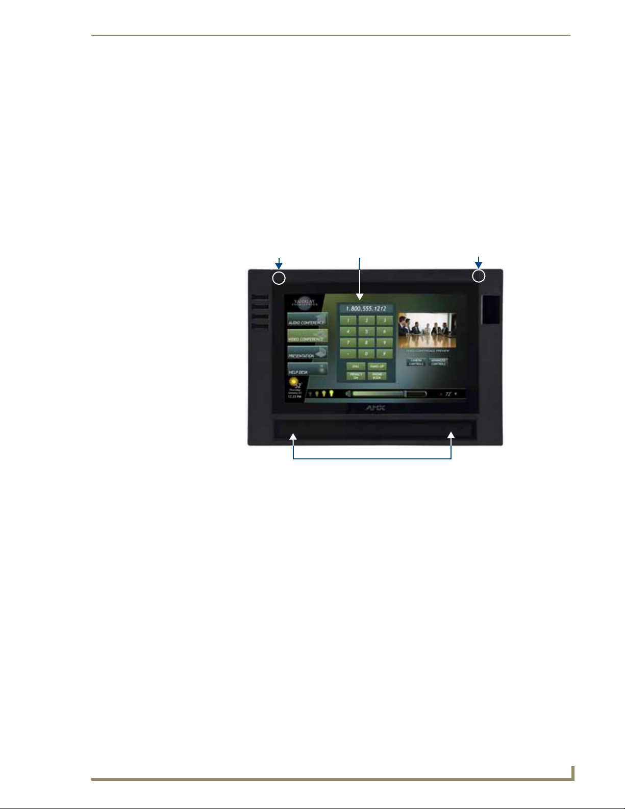
Introduction
Touch screenMicrophone
Speaker grille
Status LED
Overview
The MVP-9000i redefines touch panel control offering both wireless and wired functionality, new user
interface capabilities like gestures and animated page transitions, a stunning 9" widescreen 24-bit color
display, full digital duplex VoIP telephone or intercom interface and built-in 802.11a/b/g WiFi card with
antenna diversity. The MVP-9000i switches seamlessly to wireless mode when removed from either the MVPTDS-9 T able Docking Station or the MVP-WDS-9 Wall Docking Station. Transfer touch panel pages, upgrade
the firmware or display photo files using the USB or micro-SD card slot. Available in black (FG5967-01) and
white (FG5967-02), the MVP-9000i also features a capacitive touch directional pad, 4 progr ammable buttons,
and over 1 GB of usable flash memory. The MVP-9000i also supports 5 hours of continuous use to three days
of standby time.
Introduction
FIG. 1 MVP-9000i-GB touch panel
Common Application
The MVP-9000i is ideal for a wide variety of residential and commercial control and automation applications
where flexibility of docked with wired Ethernet or undocked with 802.11a/b/g functionality is desired. This is
an option for extremely noisy wireless environments such as multiple dwelling units, as well as applications
that require telephone/intercom functionality.
Features
Available in your choice of black or white
Capacitive touch buttons provide simple (up/down) or sophisticated control (up/down, right/left,
select)
VoIP Intercom and SIP Telephone (requires AMX SIP Gatew ay ) Ready
802.11a/b/g WiFi for two-way network communications
Wireless communications remain secure using WPA, WP A2, EAP-PEAP, EAP-FAST, EAP-LEAP,
EAP-TLS, and EAP-TTLS network security standards
Enhanced usability with microphone and speakers
Versatile placement options, including an integrated kickstand and the optional MVP-TDS-9 Table
Docking Station and MVP-WDS-9 Wall Docking Station
Page 16
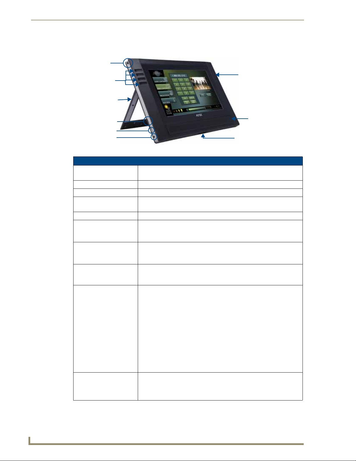
Introduction
2
MVP-9000i Modero® Wireless Touch Panel with Intercom
Kickstand
Mini-USB port
DC power jack
MicroSD memory
card slot
Docking Station
interface connector
Stylus
Speaker
Capacitive touch
Capacitive touch
buttons (4)
directional pad
The MVP-9000i comes with an integrated rear “kickstand”, allowing it to be used and displayed away from a
Docking Station (FIG. 2). It also comes with a pre-installed 802.11a/b/g wireless card.
FIG. 2 MVP-9000i side view (with kickstand)
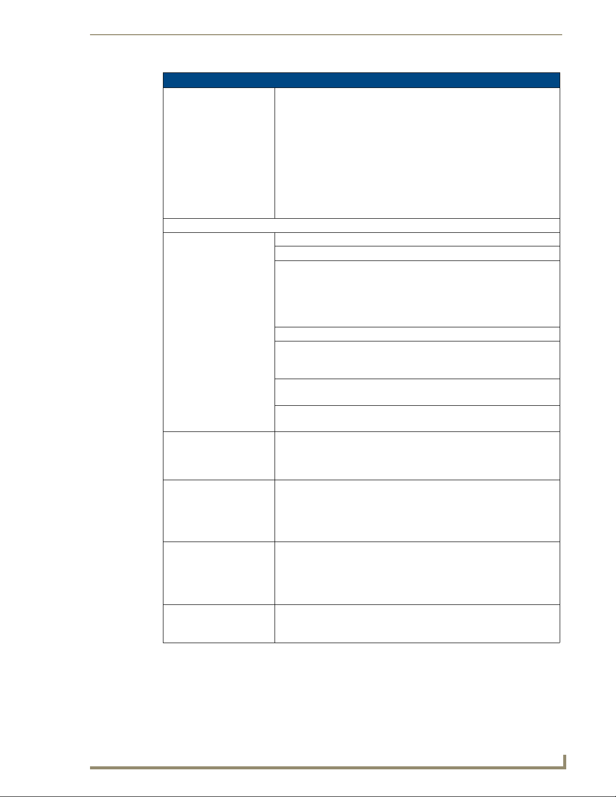
MVP-9000i Specifications
Models Available: • MVP-9000i-GB (Black - FG5967-01)
• MVP-9000i-GW (White - FG5967-02)
Dimensions: • 7.62” x 10.98” x 1.06" (19.35 cm x 27.89 cm x 2.69 cm)
Weight: • 3.60 lbs (1.63 kg)
Enclosure: MVP-9000i-GB: Black plastic with brushed metal retaining ring.
MVP-9000i-GW: White plastic with brushed metal retaining ring.
Memory: • 2GB internal microSD (1.1GB accessible to user)
Power Requirements
(Without Charging):
Power Requirements (While
Charging):
Minimum Power Supply
Required:
Power Modes: • ON: All necessary modules are powered up and device remains online with
Battery Duration: • On (continuous use): 5 hours; Standby: 3 days
• Constant current draw: 1.1 A @ 12 VDC
• Startup current draw: 1.2 A @ 12 VDC
• If panel is mounted onto a TDS or WDS, add 0.1 A to the above figures.
Panel while charging battery:
• Constant current draw: 2.0 A @ 12VDC
• If panel is mounted onto a TDS or WDS, add 0.1 A to the above figures.
• PS3.0 Power Supply (FG423-30) (included)
• PS-POE-AT High Power PoE Injector (FG423-81) through the Table Docking
Station and Wall Docking Station
the NetLinx Master.
• SLEEP: Only the backlight will be turned off after the user selectable time of
inactivity has elapsed. Panel resumes the ON mode immediately after being
touched.
• STANDBY: Power to all components other than the touch screen is turned off
after the user selectable time of inactivity has elapsed. Device will turn back
on by touching the screen. Re-acquiring an AP connection may require up to
25 seconds. (Standby Mode does not apply if a USB or microSD card is
connected to the device. For more information, please refer to the Picture
View section on page 6.)
• SHUTDOWN: Power to all peripherals and components is turned off. The
system remains in this mode until it is restarted by applying power or
touching the screen.
• 10 hours of normal use, in a combination of On, Sleep, Standby, and
Shutdown.
• 3 days of standby use
Page 17
Introduction
3
MVP-9000i Modero® Wireless Touch Panel with Intercom
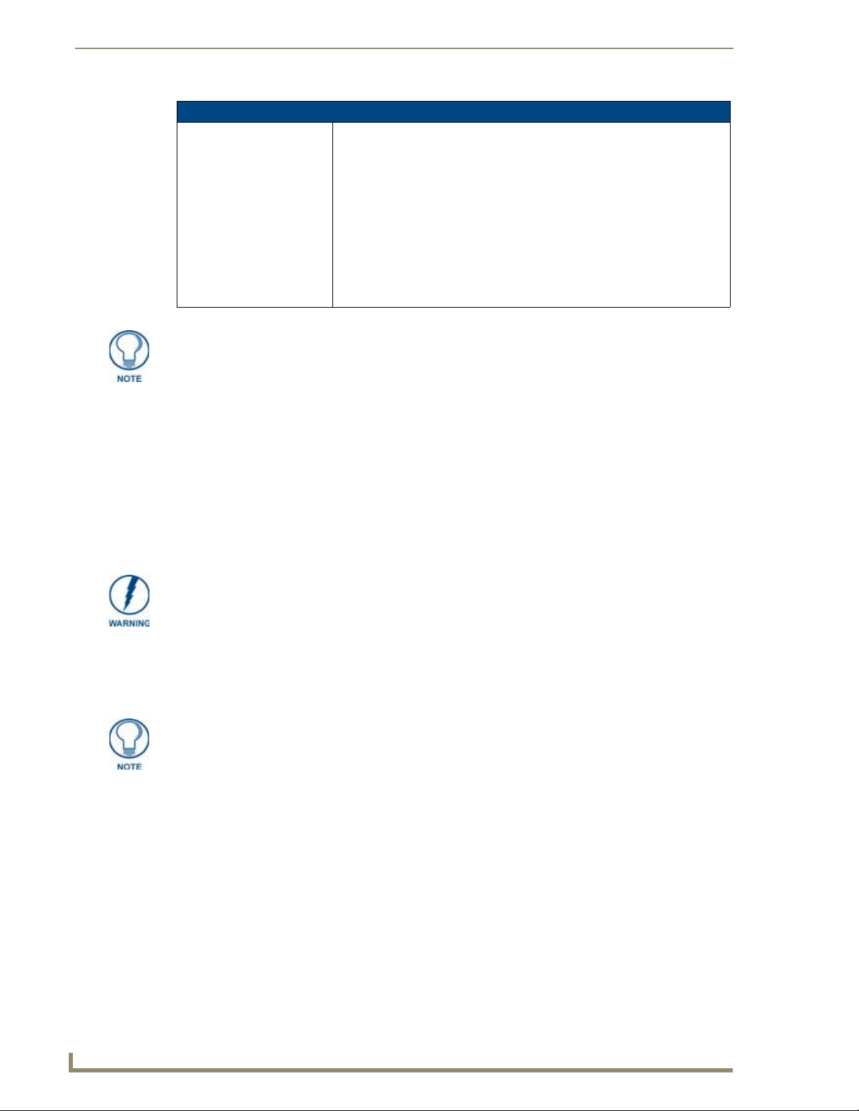
MVP-9000i Specifications (Cont.)
Panel LCD Parameters: • Screen resolution: 800 x 480 pixels (HV) @ 60 Hz refresh rate
• Aspect ratio: 16 x 9
• Brightness (luminance): 400 cd/m2
• Channel transparency: 8-bit Alpha blending
• Contrast ratio: 900:1 max.
• Display colors: 16.7M colors (24-bit color depth)
• Dot/pixel pitch: 0.246 mm
• Panel type: TFT Color Active-Matrix (IPS technology)
• Viewing angles:
Vertical: + 85° (up from center) and - 85° (down from center)
Horizontal: + 85° (left from center) and - 85° (right from center)
External Components
Stylus Slot: Slot where the included stylus is stored, located on the left side of the device.
MicroSD Card Slot: Slot for insertion of standard MicroSD memory cards.
Mini-USB Connector: 5-pin Mini-USB connector used for audio output to USB headphones,
programming, firmware updates, and touch panel file transfer between the PC
and the target panel.
Note: When connecting the panel to PC using a CC-USB (or compatible)
cable, be sure to power the panel On before attempting to connect the USB
cable from the PC to the mini-USB port on the panel.
DC power port: 2.5 mm port to power the panel away from a Docking Station.
Microphone: For use with the intercom feature and for calls using SIP.
• Frequency: 20 to 160,000 Hz
• S/N Ratio: More than 58 dB
Speaker: • 4 Ohm
• 2 Watts 300Hz cutoff frequency
Audio Standards: • G.711 sound standard
• 75dB SPL@1m
IR Emitters: Transmit IR (transmit only) over 20 feet (6.10 m) from the panel.
• IR emitters on G4 panels share the device address number of the panel.
• Transmits AMX fixed frequencies at 38KHz and 455KHz and third-party
user-programmable frequencies from 20KHz to 1.5MHz
Certifications: • FCC Class B
•CE
•IC
• VCCI
•C-Tick
Operating/Storage
Environment
Included Accessories: • MVP-9000i Installation Guide (93-5967-01)
• Operating Temperature: 0° C (32° F) to 40° C (104° F)
• Battery Charging Temperature: 0° C (32° F) to 30° C (86° F)
• Operating & Battery Charging Humidity: 20% to 85% RH
• Storage Temperature: -10° C (-14° F) to 60° C (140° F)
• Storage Humidity: 5% - 85% RH
• PS3.0 Power Supply (FG423-30)
• Stylus (pre-installed onto the left side of the unit)
Page 18
Introduction
4
MVP-9000i Modero® Wireless Touch Panel with Intercom
MVP-9000i Specifications (Cont.)
Other AMX Equipment: • MVP-TDS-9-GB Black Table Docking Station (FG5967-10)
• MVP-TDS-9-GW White Table Docking Station (FG5967-11)
• MVP-WDS-9-GB Black Wall Docking Station (FG5967-12)
• MVP-WDS-9-GW White Wall Docking Station (FG5967-13)
• CC-MINIUSB Mini USB to PC Cable Adapter (FG5967-20)
• MicroSD card - 2GB (FG2116-80)
• MicroSD card - 4GB (FG2116-81)
• MVP-BP-9 Replacement Battery Pack (FG5967-21)
• PS-POE-AT High Power PoE Injector (FG423-81)
• MVP-STYLUS-52-XX Replacement Stylus, pack of 3 (Black: FG5966-21;
White: FG5966-22)
This device complies with FCC Part 15 and Industry Canada RSS 210 subject to the
following conditions:
1. This device must not cause harmful interference and
2. This device must accept all interference, including interference that interferes with
the operation of this device.
Memory
The MVP-9000i comes with 2GB internal MicroSD memory,1.1GB of which is accessible to the user. This
memory may not be upgraded.
Connector Locations
With the unit facing you, the mini-USB port (for programming and downloading firmware and the DC power
port are located on the lower left side of the device (FIG. 2). The connector for the Table Docking Station
(please refer to the Table Docking Station section on page 11) is located on the bottom of the device.
Although firmware upgrades can be conducted over a wireless Ethernet connection,
transferring firmware KIT files over a wired LAN, USB data stick, or USB flash card is
recommended, and only when the panel is connected to a power supply. If battery
power is below 30 percent, and the touch panel is not connected to a power supply,
the download will not be completed.
In addition to its speaker, the MVP-9000i also utilizes its mini-USB port as a connector for standard
headphones or headsets. These headphones must use a mini-USB plug or adaptor in order to utilize this
feature.
While standard input/output headsets may be used in lieu of headphones, the
headset may only be used for output. While you may receive sound from the headset,
its microphone will not function. Always use the MVP-9000i’s microphone for
receiving sound.
Basic Operation
The MVP-9000i is operated using its integral touchscreen, as well as the capacitive touch buttons on the left
and the directional pad on the right side of the device (F IG. 1). If the device has gone into its Sleep or Standby
Modes, a button press will awaken the de vice from Sleep Mode, but touching the screen is the only way to
wake it from Standby Mode.
The MVP-9000i device’s power use allows up to 72 hours of use between rechargings of its internal battery,
but its battery charge lasts up to one month if the device goes into Shutdown Mode during that time. The
device may be placed in its charging cradle at any time and operated within its cradle, making a wired Ethernet
connection in the process.
If shut down, the device will power up when placed in a Table Docking Station or Wall Docking Station, or
when external power is applied via the PS3.0 Power Supply. If the device is in Standby Mode, the device will
not turn on if its side buttons or directional pad are touched or the device is docked. Touching the screen is the
only way to wake an MVP-9000i from Standby Mode.
Page 19

Introduction
5
MVP-9000i Modero® Wireless Touch Panel with Intercom
Any wired connection intended for the device will be reconnected within approximately twenty seconds after
the device is placed in a Table Docking Station or Wall Docking Station. Depending upon its settings, the
device may be set to go into On Mode as soon as it is placed in the Docking Station.
Powering on the MVP-9000i
The MVP-9000i may be powered on by touching and holding the touchscreen. If the device was in Sleep
Mode, it will automatically turn on when put into a Table or Wall Docking Station.
Intercom Microphone
The MVP-9000i contains a built-in microphone above the upper lefthand corner of the touch screen for video
and audio conferencing capabilities. This microphone is concealed by the casing.
Stylus
The MVP-9000i comes with a unique touchscreen stylus that slides into a storage groov e on the left side of the
device when not in use. Replacement styluses may be ordered in a 3-pack (black, FG5966-21; white, FG5966-
22) from www.amx.com.
Kick Stand
Since the MVP-9000i device is designed to be a unit used away from its docking station, it has an extendable
“kickstand” on the back of the unit (FIG. 2). This may be opened by physically lifting the free end of the kick
stand away from the device. The device may then be propped up on a flat surface and accessed in a normal
fashion.
Audio/Video Capabilities
The MVP-9000i has the capability of displaying multiple JPEG and PNG files at one time. The device also
supports streaming motion JPEG video (of the sort used by many IP and Web cameras) and hardware
acceleration of Motion JPEG (previously configured in TPDesign4), as well as MP3 and WAV audio files.
Power Management
The MVP-9000i utilizes a dual voltage external power supply. It may be recharged through the supplied PS3.0
Power Supply (FG423-30), as well as through the MVP-TDS-9 Table Docking Station (FG5967-1X) or the
MVP-WDS-9 W all Docking Station (FG5967-1X). For more information, see the Accessories section on
page 11 for details.
Charging Lithium Polymer batteries at high temperature will re duce the battery life.
Industry guidelines dictate that batteries should not be charged at temperatures
above 45° C (113° F). The temperature is determined by a combination of the
ambient temperature where the panel is located, plus temperature increases
normally occurring inside electronic devices containing batteries. AMX has
implemented battery temperature monitoring features to maximize the rate of battery
charging, while staying within industry temperature guidelines.
Battery charge times will increase in installations where the room temperature is
above 25° C (77° F), and may be temporarily suspended at room temperatures
above 30° C (86° F). Battery charging will automatically resume once the
temperature has fallen to appropriate levels. Minimizing the display backlight intensity
and turning off the backlight during periods of non-use will also yield faster charge
times.
Although the MVP-9000i unit is equipped with a mini-USB port, the device cannot be
powered through the USB port. The port is only used for uploading firmware.
When not in active use, the MVP-9000i conserves battery life between chargings. Pressing the touch screen
will return the device to its On Mode. For more information on the battery, see the Battery Life and
Replacement section on page 183.
Page 20

Introduction
6
MVP-9000i Modero® Wireless Touch Panel with Intercom
Cleaning the Touch Overlay and Case
Always use a clean cotton cloth and a spray bottle containing water or any standard ammonia-free glass
cleaner can be used to clean the touch screen. Do NOT use alcohol-based cleaners, as alcohol-based cleaners
can damage the device’s touch screen overlay.
Do not directly spray the device: instead, spray the cloth to clean the touch screen o verlay.
Do NOT use an abrasive of any type to clean the MVP-9000i, as this may permanently damage or
remove the device’s finish.
Picture View
Picture Vie w is a ne w feature debuti ng with the MVP-9000i. Inserting a microSD memory card into the slot on
the left side of the device, or connecting a USB drive via the mini-USB port (FIG. 2), allows the MVP-9000i to
access JPEG images on that card and display them on the touchscreen (FIG. 3). Individual images may be
accessed at any time, or the entire collection may be displayed for predetermined times. Picture View may be
stopped at any time by removing the memory card or USB drive, and the MVP-9000i will return to its default
display page.
FIG. 3 Picture View display
To start Picture View:
1. Connect a USB drive to the device or insert a microSD memory card into the microSD memory ca rd slot.
Picture View will automatically recognize all available images on the drive or memory card and start
displaying them on the touchscreen.
Page 21
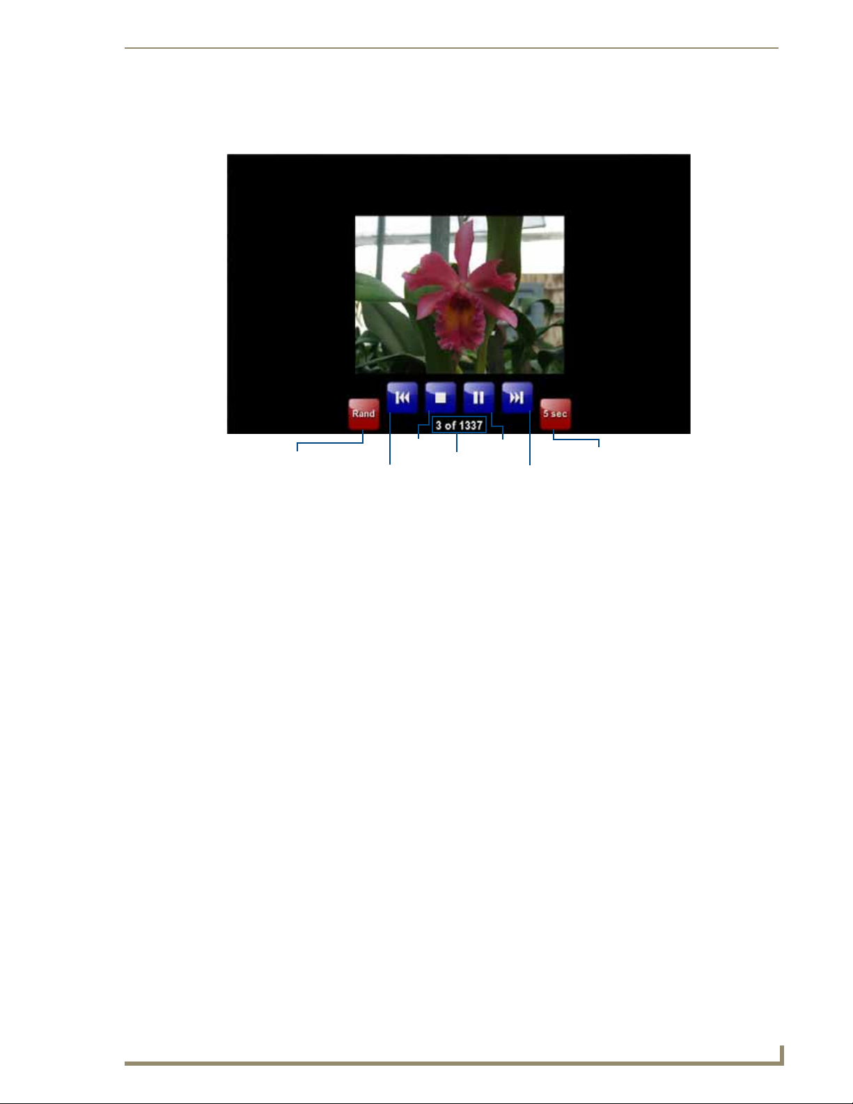
Introduction
7
MVP-9000i Modero® Wireless Touch Panel with Intercom
Previous
Stop
Pause/
Next
Counter
Resume
Random/
A-Z
Timer
2. When the images begin to display, touch any place on the touchscreen to open the configuration popup
menu (FIG. 4). If no selection is made, this menu will remain in place for 15 seconds and then disappear.
It may be accessed again by touching anywhere on the touchscreen.
FIG. 4 Picture View configuration popup menu
3. On the leftmost red button, select be tween Rand (images display at random) and A-Z (images display in
alphabetical order based on the name of the file).
4. The four blue buttons allow scrolling through saved images and the rate of display:
The Previous button returns the display to the previously displayed image.
The Stop button stops Page View and returns to the default panel page.
The Pause/Resume button allows the display to stop on one particular image. Press it again to
resume the display procession.
The Next button moves the display to the next stored image. If the MPVP-9000i has not accessed
all of the images availabl e on a USB drive or memory card, Page View will display the last one
uploaded to date.
5. On the rightmost red button, select the number of seconds a selected image will be displayed in Picture
View. This may be selected between 5, 10, 15, 30, and 60 seconds.
6. The counter beneath the buttons displays the number of images currently uploaded by the MVP-9000i
versus the number detected on the USB drive or microSD card.
Preview Mode and Normal Mode
Picture View has two modes: Preview Mode and Normal Mode. Preview Mode allows the user to configure
Picture Vi ew. Once an SD card or a USB drive containing images is inserted into the panel, the images will
begin to display. Touching any place on the display will result in the configuration popup to slide from the
bottom of the display.
Picture View goes into its Normal Mode when the MVP-9000i goes into idle timeout while connected to a
USB drive or memory card. Normal Mode displays images until the touchscreen or capacitive touch buttons
are touched, or some other wakeup event is detected. When the device goes back into timeout, Normal Mode
will return to displaying images until the USB drive or memory card are removed from the device.
Picture View Send Command
Picture Vie w may be enabled or disabled with the ^PIC Send Command. F or more information, please refer to
the ^PIC section on page 153.
Page 22
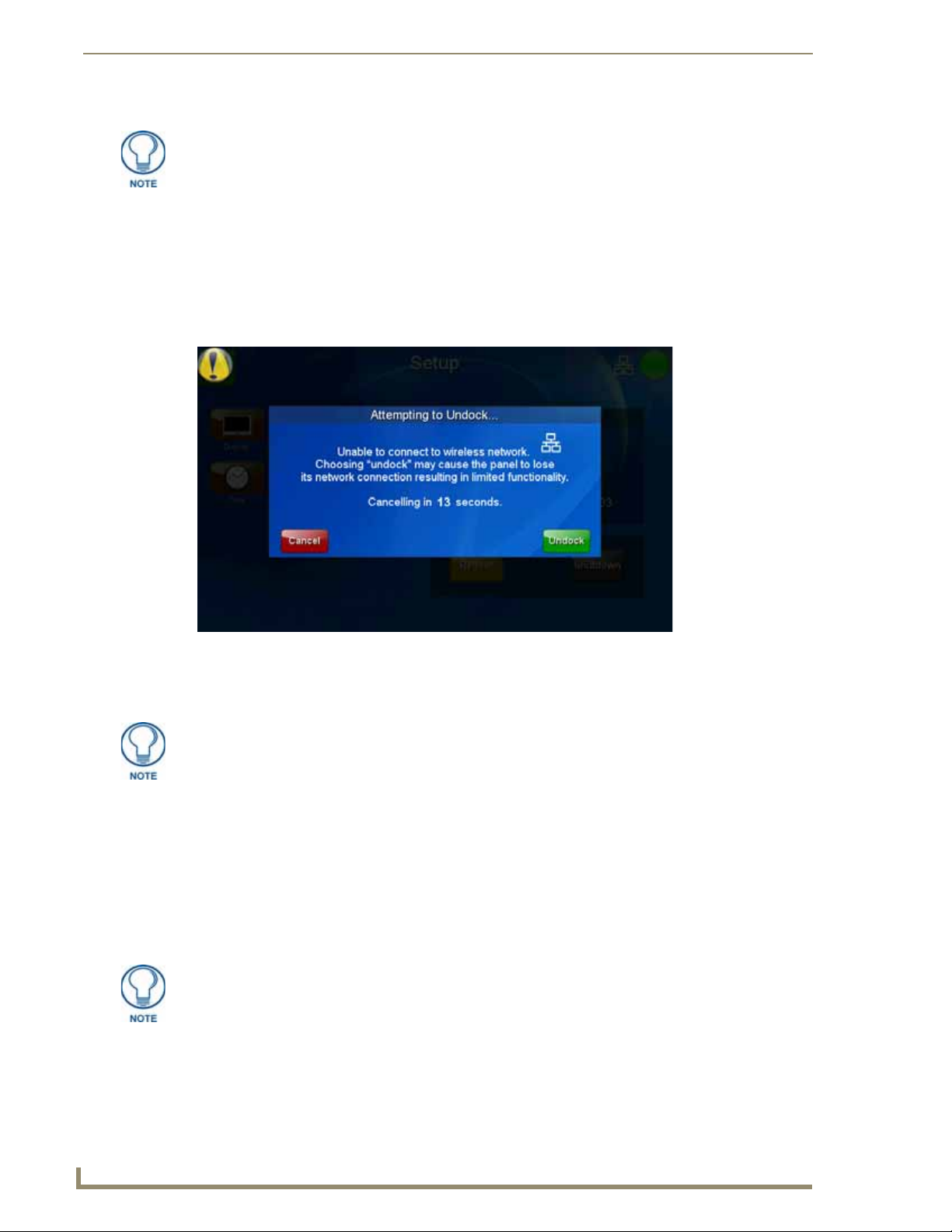
Introduction
8
MVP-9000i Modero® Wireless Touch Panel with Intercom
All images must be in JPEG format. PNG and other image formats cannot be viewed
through Picture View.
Seamless Wireless to Wired Swap
The MVP-9000i's unique design allows for wireless as well as wired connectivity with the appropriate Table
Docking Station or W all Docking Station. To prevent offline events when transitioning between wired and
wireless connectivity, the MVP-9000i allows for seamless swapping. For swapping to work correctly, the
Wired (page 72) and WiFi (page 73) network settings must be configured properly. The current connection
mode to the master is indicated by the connection icon in the upper right hand corner of the setup pages as well
as in the Current Connection field in the System Settings page under the Master tab.
FIG. 5 “Attempting to Undock” popup window
Refer to the Miscellaneous MVP Strings section on page 156 for strings that are sent to the master when the
panel is docked and undocked.
Swapping between wired and wireless connections is only supported when the
Master Mode is set to URL. For more information, please refer to the System Settings
Page section on page 70.
To swap from a wireless connection to a wired one, simply place the panel in a Table Docking Station or Wall
Docking Station. T o swap from a wired connection to a wireless connection, you must first initiate an undock
request. This can be done with the undock button on the Docking Station, or with the Undock Panel button in
the System & Panel Options page (please refer to the System & Panel Options page section on page 66). The
swap will happen once a valid password is entered (if enabled). If the panel does not swap to the master
immediately, a Confirmation Dialog popup will notify the user (FIG. 5). The user has the option to force an
undock which will cause an offline event, or to cancel the undocking and remain in the dock. If the swap is
completed sometime after the popup is displayed, the popup will disappear automatically. The popup will also
disappear after a 15-second countdown.
If an undock is initiated during a VoIP call or Dynamo session, pressing the Yes
button ends all VoIP calls in progress and Dynamo sessions.
After a successful swap from wired to wireless communication, if the panel is not removed from a Table
Docking Station after 30 seconds, the dock will automatically lock the latch and swap back to wired
communication.
Page 23

Introduction
9
MVP-9000i Modero® Wireless Touch Panel with Intercom
The firmware version of the Master controller must support swapping.
If the user does not want to use the mechanical latch on the TDS or utilize the swapping feature, the Table
Dock Latch button may be disabled or set to Off in the System & Panel Options page.
If an undock is initiated during a VoIP call or a Dynamo session, a warning popup will be displayed (FIG. 6),
allowing the user to proceed with the undock and disconnect sessions or calls, or cancel the undock
FIG. 6 Confirmation Dialog popup window for undocking
Page 24

Introduction
10
MVP-9000i Modero® Wireless Touch Panel with Intercom
Page 25
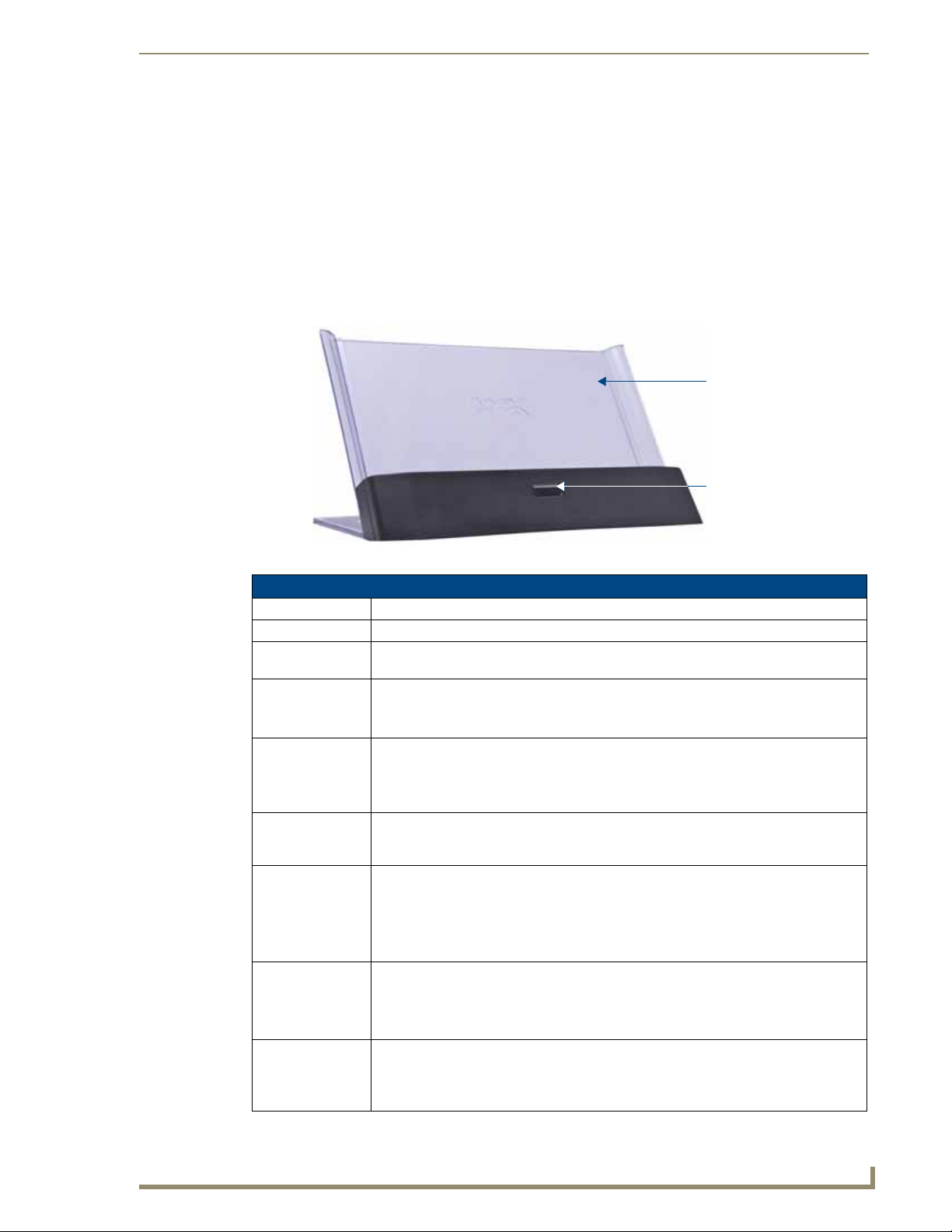
11
MVP-9000i Modero® Wireless Touch Panel with Intercom
Accessories
Docking Station cradle
Release button
Table Docking Station
The Power-over -Ethernet MVP-TDS-9 Table Docking Station (FIG. 7) charges the MVP-9000i and provides a
wired Ethernet connection when the panel is docked. The MVP-TDS-9's sleek design allows the panel to slide
into perfect placement in the docking station and includes password protection support for panel removal.
When the MVP-9000i is placed into the PoE docking station, it automatically switches from wireless to wired
Ethernet communication. The Docking Station is available in either black (MVP-TDS-9-GB, FG5967-10) or
white (MVP-TDS-9-GW, FG5967-11).
Accessories
FIG. 7 MVP-TDS-9-GB Table Docking Station - Front
MVP-TDS-9 Specifications
Dimensions (HWD): • 6.25” x 11.50” x 5.50” (15.88cm x 29.21cm x 13.97cm)
Weight: • 1.25 lbs (.57 kg)
Power
Requirements:
Startup Power
Requirements:
Front Components: • Docking Station cradle: for supporting the device while connected or charging.
Rear Components: • 2 USB ports on the left side of the device, for firmware or file download to a docked
Operating/Storage
Environments:
Included
Accessories
Other AMX
Equipment:
• 30 W (Class II listed power supplemented), supplied via the PS-POE-AT High-Power
PoE Injector.
• Cradle and panel (not charging): 16 W
• Cradle and panel (charging): 23 W
• Ejection: 23 W
• Release button: before removing the MVP touch panel, press this button to switch the
panel from a wired to a wireless Ethernet connection to its network.
• 12-pin charging connector on bottom of device cradle.
touch panel. These ports may also be used for using a keyboard and/or mouse with the
touch panel.
• Operating Temperature: 0° C (32° F) to 40° C (104° F)
• Battery Charging Temperature: 0° C (32° F) to 30° C (86° F)
• Operating & Battery Charging Humidity: 20% to 85% RH
• Storage Temperature: -10° C (-14° F ) to 60° C (140° F)
• Storage Humidity: 5% - 85% RH
• MVP-TDS-9 Table Docking Station Installation Guide (93-5967-10)
• PS-POE-AT High Power PoE Injector (FG423-81)
• Ethernet cable - black (ECA5967-22BL) (for MVP-TDS-9-GB)
• Ethernet cable - white (ECA5967-22WH) (for MVP-TDS-9-GW)
• MVP-9000i Modero Viewpoint Widescreen Touch Panel with Intercom - Black
(FG5967-01)
• MVP-9000i Modero Viewpoint Widescreen Touch Panel with Intercom - White
(FG5967-02)
Page 26
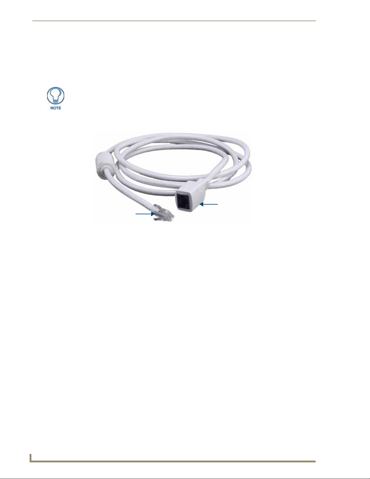
Accessories
12
MVP-9000i Modero® Wireless Touch Panel with Intercom
To input port on
the MVP-TDS-9
To Ethernet cable connected
to PS-POE-AT
Powering the MVP-TDS-9
The MVP-TDS-9 uses the PS-POE-AT High-Power PoE Injector (FG423-81) to provide direct power for the
MVP panel via a standard Ethernet connection, both for standard function and for char ging its internal battery.
This also allows a wired Ethernet connection for the panel, and the panel may be used normally while docked
in the MVP-TDS-9 without the need for a wireless connection.
Use only the RJ45 plug on the included Ethernet cable with the MVP-TDS-9. Other
RJ45 plugs will not fit in the device’s jack, and attempting to use another plug may
damage the jack. If necessary, the cable may be spliced and shortened for special
installations.
For both Ethernet connection and for power for the MVP-9000i, the MVP-TDS-9 uses a special Ethernet cable
(FIG. 8) in order to connect to the PS-POE-AT.
FIG. 8 MVP-TDS-9 cable
To connect the MVP-TDS-9 to the PS-POE-AT via the special Ethernet cable:
1. Connect the terminal end of the cable to the PWR connector on the bottom of the MVP-TDS-9.
2. T o pre vent wear on the po wer supply cord and assure that the de vice’s base is in full contact with the table
surface, press the cord into the locking groove running across the bottom of the device (FIG. 9).
3. The other end of the included Ethernet cable has an input port, intended for a standard RJ45 jack. Use a
standard Ethernet cable to connect the Ethernet/PoE port to the PS-POE-AT plugging the other end of the
Ethernet cable into the Data & Power Out RJ45 port on the PS-POE-AT. Make sure that the PS-POE-AT’s
power cable is connected to the device and to an available power source, and that the incoming Ethernet
cable accessing the Data In RJ45 jack is connected to the desired network.
4. Place the touch panel in the Docking Station cradle, guidin g it into place with the locking groove s on each
side of the cradle (FIG. 9). When fully seated, the touch panel’s Docking Station connector should be in
contact with the Docking Station’s charger pins.
Page 27

Accessories
13
MVP-9000i Modero® Wireless Touch Panel with Intercom
Charger pins
Docking Station cradle
Locking groove
USB ports (2)
Recharging
T o rechar ge the MVP-9000i, slide the device into the T a ble Docking Station cradle bottom-first and make sure
the device is fully seated in the Docking Station. Th e char ger pins in the bottom of the cradle (FIG. 9) must be
in contact with the connector on the bottom of the MVP-9000i for it to start recharging. The MVP panel will
stop recharging automatically once the battery has achieved its maximum charge.
FIG. 9 MVP-TDS-9-GW Table Docking Station - Rear
Using the USB ports
The MVP-TDS-9 has two USB ports on the lef t of the device behind the Docking Station cradle (FIG. 9).
These ports may be used for transferring files to the MVP-9000i, as well as ports for USB-powered
accessories.
Undocking the Touch Panel
For information on removing a touch panel locked into the MVP-TDS-9, please refer to the Undock ing from
the MVP-TDS-9 or MVP-WDS-9 section on page 22.
Cleaning the MVP-TDS-9
You should clean the MVP-TDS-9 Table Docking Station after each day’s use to maintain the device’s
appearance. Always use a clean cotton cloth and a spray bottle containing water or a non-ammonia-based
cleaner, as alcohol-based cleaners can damage the device. Do not directly spray the device: instead, spray the
cloth to prevent moisture from collecting on the char ger pins. Do NOT use an abrasive of any type to clean the
Table Docking Station, as this may permanently damage or remove the device’s finish.
Page 28
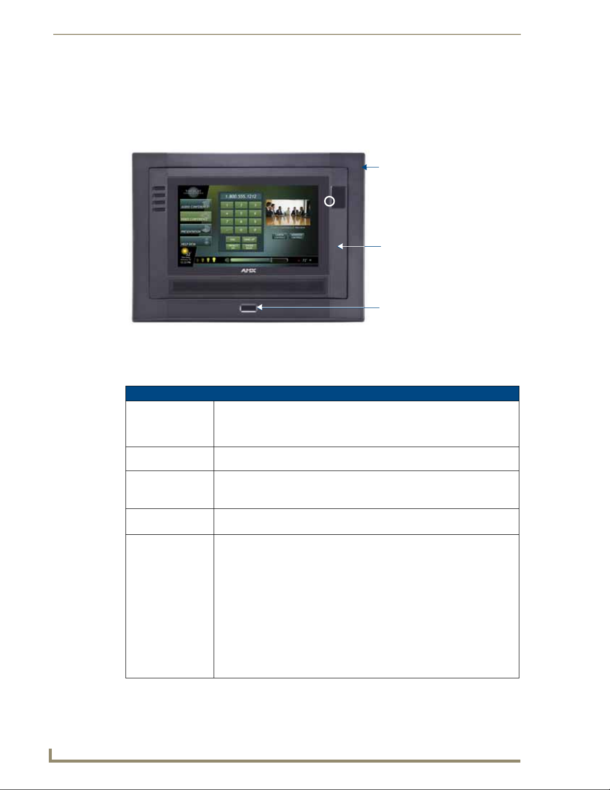
Accessories
14
MVP-9000i Modero® Wireless Touch Panel with Intercom
Security Release button
MVP-9000i
MVP-WDS-9
Wall Docking Station
While charging the MVP-9000i, the Power-over-Ethernet MVP-WDS-9 Wall/Flush Mount Docking Station
provides fast, reliable wired Ethernet communication to the touch panel. In addition, the MVP-WDS-9
employs a unique, anti-theft locking mechanism to keep the touch panel safe and secure. With a push of a
button, the panel glides forward for simple removal and transport. The Wall Docking Station is available in
either white (FG5967-13) or black (FG5967-12).
FIG. 10 MVP-WDS-9-GB Wall Docking Station - Front
The features of the MVP-WDS-9 include:
Touch panel password feature for security
Integrated docking alignment guides for easy docking.
MVP-WDS-9 Specifications
Dimensions (HWD): • 9.75" x 12.50" x 2.13" (24.77cm x 31.75cm x 5.40cm)
Note: Always use the cutout/installation dimensions for the MVP-WDS-9 when
installing this unit into various surfaces. This SP engineering drawing is available
online at www.amx.com.
Power Requirements: • 30 W (Class II listed power supplemented), supplied via the PS-POE-AT High-
Power PoE Injector.
Startup Power
Requirements
Weight: • Without back box: 1.50 lbs (0.68 kg)
Front Panel
Components:
• Cradle and panel (not charging): 16 W
• Cradle and panel (charging): 23 W
• Ejection: 23 W
• With back box: 2.40 lbs (1.09 kg)
• Securing Magnets: Secures MVP touch panel during ejection.
• Security Latch: Adds the primary layer of security when mounting an MVP touch
panel. When the device is inserted, this latch grabs onto the rear of the touch panel
and secures it to prevent it from inadvertently being removed.
• Interface Connector: A set of contacts that connect to the underside MVP connector
strip. This connection provides both communication and power between the touch
panel and the MVP-WDS-9.
• Support Cradle: This retractable mechanism supports a resting MVP panel and
allows a user to either insert or remove a connected MVP panel.
• Security Release pushbutton: Located on the front of the unit, this pushbutton
toggles an on-screen security keypad if security is enabled.
- Entering the correct release code allows the MVP-WDS-9 to release the touch
panel from the security latch.
Page 29
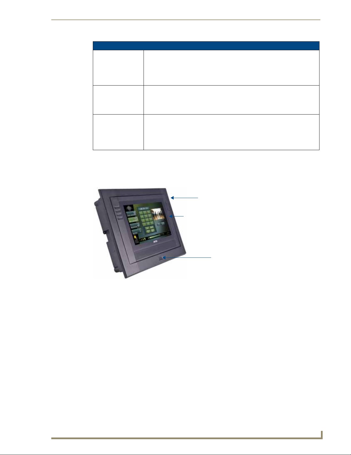
Accessories
15
MVP-9000i Modero® Wireless Touch Panel with Intercom
MVP-9000i
Wall Docking Station
Security Release button
MVP-WDS-9 Specifications (Cont.)
Operating/Storage
Environments:
Included Accessories • MVP-WDS-9 Wall Docking Station Installation Guide (93-5967-12)
Other AMX Equipment: • MVP-9000i-GB Modero Wireless Touch Panel, Black (FG5967-01)
• Operating Temperature: 0° C (32° F) to 40° C (104° F)
• Battery Charging Temperature: 0° C (32° F) to 30° C (86° F)
• Operating & Battery Charging Humidity: 20% to 85% RH
• Storage Temperature: -10° C (-14° F ) to 60° C (140° F)
• Storage Humidity: 5% - 85% RH
• Snap-On Ferrite (04-0007)
• MVP-WDS-9 Wall Docking Station Template (68-5967-01)
• PS-POE-AT High Power PoE Injector (FG423-81)
• MVP-9000i-GW Modero Wireless Touch Panel, White (FG5967-02)
• MVP-TDS-9-GB Black Table Docking Station (FG5967-10)
• MVP-TDS-9-GW White Table Docking Station (FG5967-11)
• CB-MVP-WDS9 Rough-In Box (FG038-13)
The MVP-9000i touch panel remains locked in the MVP-WDS-9 until unlocked by the user . This may be done
by entering an appropriate password (please refer to the Passwords section on page 97 for more information),
or by pressing the Security Release button on the front of the device in emergencies. The station ejects the
device top first. The device uses two neodymium rare-earth magnets to keep the MVP-9000i from falling out
of its cradle when the touch panel is angled forward.
FIG. 11
MVP-WDS-9-GB Wall Docking Station - Side view
Unlocking the Touch Panel
For information on removing a touch panel locked into the MVP-WDS-9, please refer to the Und ocking from
the MVP-TDS-9 or MVP-WDS-9 section on page 22.
Page 30
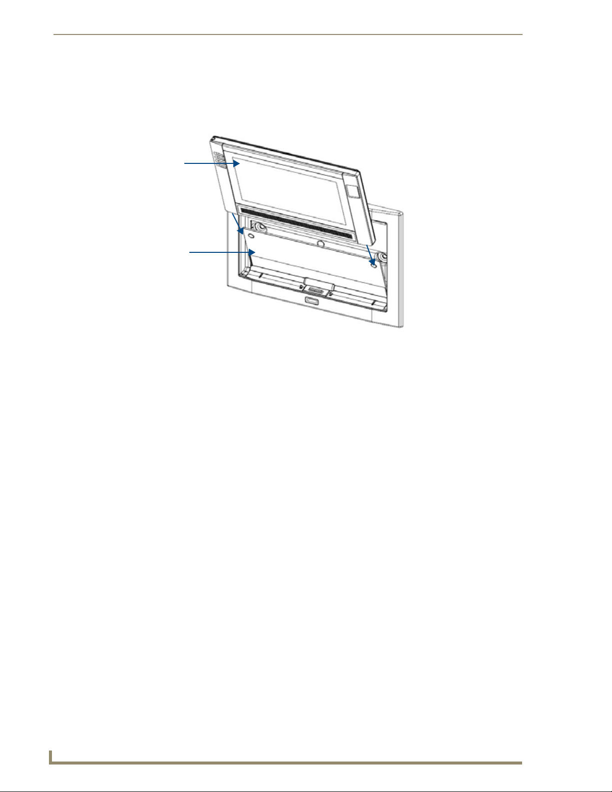
Accessories
16
MVP-9000i Modero® Wireless Touch Panel with Intercom
MVP-9000i
MVP-WDS-9
Recharging
To recharge the MVP-9000i:
1. Slide the device into the Wall Docking Station cradle bottom-first an d make sure the de vice is fully seated
in the Docking Station (FIG. 12).
FIG. 12 Inserting the MVP-9000i into the MVP-WDS-9
2. Press the top of the MVP-9000i back until it clicks. The touch panel is now locked into the Docking
Station, and the station will automatically charge the device’s battery. (Please refer to the Power
Management Page section on page 53 to check on the battery charge status.)
3. To release the touch panel, unlock the touch panel and wait for the Wall Docking Station to pivot the
touch panel away from the wall (FIG. 18).
Page 31

Accessories
17
MVP-9000i Modero® Wireless Touch Panel with Intercom
8.25"
(212.7mm
5.56"
(141.29mm)
5.56"
(141.29mm)
8.25"
12.06"
(30.64 cm)
12.06"
(30.64 cm)
8.69"
(22.07 cm)
8.69"
(22.07 cm)
Installing the MVP-WDS-9
Since the W all Docking Station is intended to be affixed to a wall or other permanent structure, care must be
taken to ensure its proper installation to prevent potential damage to the MVP-9000i placed within.
Other than wall installation tools, the only tool required for this installation is a #2
Phillips screwdriver.
Installing the Wall Docking Station and Plastic Back Box
The Plastic Back Box has two pairs of knockouts at the top of the box and four (4) lockdo wn wings attached to
the box with Phillips-head screws. For ease of installation, the interior of the box contains an “UP” arrow
pointing to the knockouts.
The optional CB-MVP-WDS9 Metal Rough-In Box is not required for installation of
the supplied Plastic Back Box, but it offers an extra level of support.
To install the Plastic Back Box:
1. Cut a hole into the wall or surface intended to hold the back box. The back box is sized 12 1/16 inches
(30.64 cm) long and 8 11/16 inches (22.07 cm) high, so the hole should be at least 1/4” (6.4mm) smaller
in each dimension (FIG. 13). Use the included MVP-WDS-9 Wall Docking Station Template (68-5967-
01) as an aid for hole placement and measurement.
FIG. 13 Recommended cutout for the MVP-WDS-9 plastic back box
Make sure to measure the size of the intended hole before starting to cut it. Cutting
the hole slightly smaller than the dimensions to allow for adjustments is highly
recommended.
2. Select the knockout to be removed from the top of the box. The box has two knocko uts, at the top left and
the top right.
To assist with wiring, and to avoid mechanical stresses on the wire and the
mechanism of the Wall Docking Station, the top left knockout, when viewing the
device from the rear, is preferred for use for Ethernet installation. Use the top right
knockout for USB cable connection.
Page 32

Accessories
18
MVP-9000i Modero® Wireless Touch Panel with Intercom
Knockout placement
in back box
Recommended Ethernet installation
Recommended USB installation
Ethernet port
Ferrite installation
position
Recommended
Ethernet cable
path
3. Connect the PS-POE-AT High-Power PoE Injector to a power source. Connect the PS-POE-AT to an
Ethernet switch on the network via one length of Ethernet cable and insert one length of Ethernet cable
for connection to the Wall Docking Station.
4. Run the Ethernet cable through the knockout into the back box. Pull out about six inches (15.25cm) of
cable into the back box to facilitate installation of the MVP-WDS-9.
5. Slide the plastic back box into the hole, being careful not to twist or pinch the cable, and set it flush with
the wall.
Make sure that all of the lockdown wings are folded into their slots before attempting to insert the
box.
For ease of installation, the inside of the box has the direction “UP” labeled for reference.
6. Extend the wings on the sides of the box by tightening the screws inside the box.
Not all of the wings must be e xtended to lock th e box in place, but extending a minimum of the top
and bottom wings is highly recommended.
Apply enough pressure to the screw head to keep the box flush with the wall: this ensures that the
wing will tighten up against the inside of the wall.
Make absolutely certain that the box is in its intended position. Once the box
lockdown wings are extended within the box’s hole within the wall, removing the box
will be extremely difficult without damaging the wall in the process.
The maximum recommended torque to screw in the wings on the plastic back box is
5 IN-IBS [5(NI-CM)]. Applying excessive torque while tightening the wing screws,
such as with powered screwdrivers, can strip out the wings or damage the plastic
back box.
7. Attach the included snap-on ferrite to the Ethernet cable, as close to the RJ-45 connector as possible.
Attach the cable to the Ethernet Port (FIG. 14).
FIG. 14 MVP-WDS-9 - Ethernet cable path
8. Firmly seat the device against the back box. Make sure that the tab connector at the bottom of the device
is locked into the back box.
9. Insert the two installation screws from the MVP-WD S-9 Installation Kit into the screw holes in the
interior compartment of the device and tighten them to anchor the device to the back box.
For ease of installation, put each screw on a neodymium magnet in the device’s
interior compartment to keep them on hand until they are needed.
Page 33

Accessories
19
MVP-9000i Modero® Wireless Touch Panel with Intercom
10. After fully seating the screws, wipe down the area around the screw holes with the alcohol prep p ad from
the Installation Kit. Take a rubber foot and remove its adhesive backing. Put the foot, adhesi v e-side down,
in the slot surrounding the screw hole in the Wall Docking Station. Press down firmly to remove any air
bubbles from underneath the foot.
11. Install an MVP-9000i device by placing it into the interior compartment bottom-first. Press the top of the
touch panel until it is flush with the Wall Docking Station. The neodymium magnets will hold it in place.
12. T o remov e the MVP-9000i, unlock the touch panel (see the Unloc king the Touch P anel section on page 15
for more information) and wait for the touch panel to pull away from the Wall Docking Station. Once it
has been released, grip it by the top of the device, and pull it free from the Docking Station.
Page 34

Accessories
20
MVP-9000i Modero® Wireless Touch Panel with Intercom
Screws for
Dry Wall Clips
Front Cover
Mounting Screws
Dry Wall Clips
A
B
Installing the Optional Metal Rough-In Box
The optional metal rough-in box (FG038-13) is 11.97 inches (30.40cm) wide at its widest dimension (wider
than the bezel of the W all Docking Station), and is only intended for pre construction installations (FIG. 15).
The Metal Rough-In Box is used in conjunction with the Wall Docking Station’s plastic back box.
In order to guarantee a stable installation of the MVP-WDS-9, the distance between
the CB-MVP-WDS9 and the outer wall surface must be a minimum of .50 inches
(1.27cm) and a maximum of .1.50 inches (3.81cm).
.
FIG. 15 CB-MVP-WDS9 Rough-In Box - with front cover
Pre-Wall Installation of the CB-MVP-WDS9
1.
Remove the rough-in box cover (A in FIG. 15) before installation of the Rough-In Box (B).
The cover MUST be removed before drywall installation. The cover may be
reinstalled after drywall installation using 4-40 screws (not included).
2. Fasten the CB-MVP-WDS9 rough-in box to the stud through the holes on the Stud Mounting Ta bs, using
either nails or screws (not provided).
Ensure that the metal rough-in box is flush with the 2x4 studs. Any overhang will
affect the installation of the covering sheetrock, as well as affect the placement of the
Plastic Back Box.
3. Remove the appropriate wiring knockouts from the rough-in box to accommodate the cables being
threaded through to the MVP-WDS-9.
Make sure that the power cable has been pulled through the metal rough-in box by
the resident electrician before continuing the installation.
4. Thread the incoming Ethernet and USB wiring through the knockouts. Using the left wiring knockouts
for USB connector cables and the right wiring knockouts for the LAN/PoE In cable is very highly
recommended with this installation. Leave enough slack in the wiring to accommodate installation of the
docking station.
5. Install the drywall/sheetrock before inserting the back box for the CB-MVP-WDS9.
Page 35

Accessories
21
MVP-9000i Modero® Wireless Touch Panel with Intercom
6. Cut out the opening for the MVP-WDS-9 where the wall has been placed ov er the Rough-In Box. Cutting
out the surface slightly smaller than what is outlined in the installation drawings, so that you can make
any necessary cutout adjustments, is very highly recommended.
Other MVP-WDS-9 installations
The W all-Mounted Docking Station is designed to be installed in various diffe rent locations, such as into the
face of a wooden podium or the top of a table. Depending upon the ability to wire it to a power source, WallMounted Docking Stations may be installed on vertical or horizontal surfaces composed of such materials as
wood, brick, and glass.
Installing a W all-Mounted Docking Station into a solid wall thicker than a standard thickness of sheetrock is
possible, but requires special preparation. If installing into a solid wall of concrete or rock, a recess must be
chiselled or cut out to match the size of the device. The box is sized 8.375 inches (21.27cm) long and 5.75
inches (14.60cm) high, so the hole should be at least 1/4” (0.64cm) smaller in these dimensions. To facilitate
the full range of movement of the device’s components, the recess must be at least 2.69 inches (6.83cm) deep.
Ensure that the power cable has been installed in the wall and is accessible by the
installer before chiseling out the recess.
Instead of using the lockdown wings to secure the Plastic Back Box, standard
concrete screws may be inserted through the screw holes after removing the
lockdown wings.
However, drill the concrete screw holes into the wall before setting the screws into the
box, as excessive torque applied to the screws will damage the box.
T o avoid this, the box may be installed with adhesive. Test an unobtrusive spot on the
back of the box with a sample of the adhesive to check for any adverse reactions
before installing the device.
Page 36

Accessories
22
MVP-9000i Modero® Wireless Touch Panel with Intercom
Undocking from the MVP-TDS-9 or MVP-WDS-9
Once placed within either the Table Docking Station or the Wall Docking Station, the MVP-9000i remains
secured until the user unlocks it. A ten-second lag between the touch panel being placed in either Docking
Station and the security feature enabling allo ws the use r to remove the touch panel if it is accidentally put into
the device. To release the touch panel from either Docking Station:
1. Press the Release button (see FIG. 7 for the Table Docking Station or FIG. 11 for the Wa ll Docking
Station).
2. A password keypad will pop up on the MVP-9000i screen. Enter a passw ord in the passw ord keypad and
press Enter.
Unique passwords may be entered for up to four unique users as well as the
administrator. For more information on setting passwords, please refer to the
Passwords section on page 97.
3. If the MVP-9000i was conducting a SIP call or Dynamo session at this time, a confirmation dialog
window appears to warn that any open sessions or calls will end (FIG. 16). Click Yes to undock the panel
and disconnect the call/session, or No to keep the panel in the Docking Station and continue the call/
session.
FIG. 16 Undocking confirmation dialog window
Page 37

Accessories
23
MVP-9000i Modero® Wireless Touch Panel with Intercom
MVP-9000i
MVP-WDS-9
4. When disconnecting from a Docking Station, the MVP-9000i will attempt to switch from a Wired to
Wireless connection. If the touch panel is unable to connect to a wireless network, a conf irmation window
appears warning that the panel will lose its network connection (FIG. 17). Press Undock if you still wish
to remove the touch panel, or Cancel to keep the panel in the Docking Station. If you do not choose either
option, the undocking attempt will automatically cancel within 15 seconds.
FIG. 17 “Attempting to Undock” confirmation window
5. When disconnecting from a W a ll Docking Station, wait for the Wall Docking Station to pivot the touch
panel away from the wall (FIG. 18).
FIG. 18 Ejected position for the MVP-9000i
6. Remove the device. The device will remain in the ejected position in the MVP-WDS-9 until the MVP-
9000i is removed. Wait until the MVP-WDS-9’s ejection door has completely withdrawn before reinstalling the MVP-9000i.
Page 38

Accessories
24
MVP-9000i Modero® Wireless Touch Panel with Intercom
Page 39

25
MVP-9000i Modero® Wireless Touch Panel with Intercom
Configuring Communication
Network Master
IP
Network
802.1 1 a/b/g AP
Panel 1
Panel 2
Panel 3
Overview
All control for a MVP-9000i touch panel is established through a NetLinx Master. Communication between
the MVP and the Master consists of using wired LAN, Wireless Ethernet (DHCP, Static IP) or USB.
References to Ethernet in this manual focus on the use of Wireless Ethernet via the MVP’s WiFi Card.
Before commencing, verify you are using the latest NetLinx Master and Modero
panel-specific firmware. Verify you are using the latest versions of AMX’s NetLinx
Studio and TPDesign4 programs.
In the example below (FIG. 19), three MVP-9000i devices are shown at varying distances from an AP
gateway . As with an y other AP network, the gate way is spaced so as to allow a maximum wireless coverage for
the three devices.
Configuring Communication
FIG. 19 System Deployment Diagram
When initially installing the MVP-9000i, some basic configuration items, including network settings and
NetLinx settings, will need to be set. For more information, refer to the Protected Setup Pages section on
page 63.
The MVP-9000i defaults to Ethernet and Auto mode for its Master connection.
Page 40

Configuring Communication
26
MVP-9000i Modero® Wireless Touch Panel with Intercom
IR Emitter Panel
IR Communication
In certain situations, the MVP-9000i may be used as an infrared remote device for other AMX controllers. The
device can transmit IR over 20 feet (6.10 m) from the panel at AMX frequencies of 38KHz and 455KHz, and
third-party device frequencies between 20KHz and 120KHz. IR receivers and transmitters on G4 panels share
the device address number of the panel.
The MVP-9000i includes an IR transmitter for communication between the device and the NetLinx Master
and between separate devices. The transmitter is located behind the IR Emitter Panel on the rear of the device
(FIG. 20).
FIG. 20 IR transmitter window on the MVP-9000i-GB
Modero Setup and System Settings
All AMX Modero panels, including the MVP-9000i, feature on-board Setup pages. Use the options in the
Setup pages to access panel information and make various configuration changes.
Accessing the Setup and Protected Setup Pages
1.
At any time, hold the bottom left capacitive touch button and the bottom of the directional pad for 3
seconds. Alternately, press the Reset button on the left side of the device and hold it for 6 seconds. (For
more information, please refer to the Accessing the Setup pages section on page 47.) This opens the
Status page (FIG. 21).
FIG. 21 Status page
Page 41

Configuring Communication
27
MVP-9000i Modero® Wireless Touch Panel with Intercom
2. Press the Protected button. This opens a popup keypad for password entry(FIG. 22). Enter the device’s
password and press Done to proceed to the Protected Setup page (FIG. 23).
FIG. 22 Protected Setup password popup window
The default password for the Protected Setup page is 1988, but this may be changed
at any time.
FIG. 23 Protected Setup page
For more information on the Setup and Protected Setup pages, refer to the Setup Pages section on page 47 and
the Protected Setup Pages section on page 63.
Setting the Panel’s Device Number
In the Protected Setup page:
1. Press the Device Number field in the Device Information section to open the Device Number keypad.
2. Enter a unique Device Number assignment for the device , and press Done to return to the Pr otected Setup
page. The Device Number default is 0.
3. From the Setup page, press Reboot to reboot the device and apply the new Device Number.
Page 42

Configuring Communication
28
MVP-9000i Modero® Wireless Touch Panel with Intercom
Wireless Settings - Wireless Access Overview
DHCP
When choosing DHCP, a DHCP server must be accessible before the IP, subnet, and gateway fields are
populated.
The parameters of the wireless card must be set before selecting Ethernet as the Master Connection T ype. The
Wireless Access Point communication parameters must match those of the pre-installed wireless CF
card inside the device.
MVP touch panels connect to a wireless network through the use of a pre-installed AMX 802. 11a/b/g wireless
interface card. This allows users to communicate via a wireless LAN. For a more detailed explanation of the
new security and encryption technology, refer to the Appendix B: Wireless Technology section on page 197.
For more information on utilizing the AMX Certific ate Upload Utility in conjunction with the EAP security,
refer to the AMX Certificate Upload Utility section on page 203.
Configuring Wireless Network Access
The first step in connecting the MVP-9000i to a wireless netw ork is to configure the wireless communication
parameters within the device’s System Settings page. This is done via the System Settings page, which allows
configuration of the IP Address, System Number and Username/Password information assigned to the target
Master.
Step 1: Configure the Device’s WiFi Settings
The first step to a successful setup of the internal wireless card is to configure the WiFi tab on the System
Settings page. This section configures the communication parameters from the MVP panel to the web.
Wireless communication using a DHCP Address
In the Protected Setup page:
1. Touch the Network button to open the System Settings page.
2. Select the WiFi tab (FIG. 24).
FIG. 24 System Settings page - WiFi tab
3. Toggle the DHCP/Static field until the choice cycles to DHCP. This action causes all fields in the IP
Settings section, other than Host Name, to be greyed-out.
Page 43

Configuring Communication
29
MVP-9000i Modero® Wireless Touch Panel with Intercom
4. Press the optional Host Name field to open the Host Name keyboard (FIG. 25) and enter the host name
information. The default name is "localhost".
FIG. 25 Host Name keyboard
5. Press OK after assigning the alpha-numeric string of the host name.
6. The remaining greyed-out fields in the IP Settings section cannot be altered. Once the panel is rebooted,
these values are obtained by the unit and displayed in the DNS fields after power-up.
This information can be found in either the Workspace - System name > Define
Device section of the code that defines the properties for the panel, or in the Device
Addressing/Network Addresses section of the Tools > NetLinx Diagnostics dialog.
7. Set up the security and communication parameters between the wireless card and the target AP by
configuring the W ireless Settings section on this page. Refer to Step 2: Configure the Card’s Wireless
Security Settings section on page 32 for detailed procedures to setup either a secure or insecure
connection.
Wireless Communication Using a Static IP Address
1.
From the Protected Setup page, press the Network button to open the System Settings page. Wireless
communication is set within the WiFi tab of this page (FIG. 24).
Check with your System Administrator for a pre-reserved Static IP Address to be
assigned to the panel. This address must be obtained before continuing with the
Static assignment of the panel.
2. Toggle the DHCP/Static field until the choice cycles to Static. The IP Address, Subnet Mask, and
Gateway fields then turn red, noting that they are now user-editable.
3. Press the IP Address field to open a keyboard and enter the Static IP Address provided by the System
Administrator. Press OK after entering the IP address information and repeat the same process for the
Subnet Mask and Gateway fields.
4. Press the optional Host Name field to open the keyboard and enter the Host Name inform ation. Press OK
after assigning the alpha-numeric string of the host name.
5. Press the Primary DNS field to open a Keyboard, enter the Primary DNS Address (provided by the
System Administrator) and press OK when compete. Repeat this process for the Secondary DNS field.
6. Press the Domain field to open a Keyboard, enter the resolvable domain Address (this is provided by the
System Administrator and equates to a unique Internet name for the panel), and press OK when
complete.
Page 44

Configuring Communication
30
MVP-9000i Modero® Wireless Touch Panel with Intercom
7. Set up the security and communication parameters between the wireless card and the target AP by
configuring the information on the second page of the WiFi tab. Refer to the follo wing section for detailed
procedures to set up either a secure or unsecure connection.
Using the Wireless Site Survey Tool
This tool allows a user to “sniff out” all transmitting Wireless Access Points within the detection range of the
internal wireless card (FIG. 26). Once the Site Survey button is pressed, the device displays the Wireless Site
Survey page, which contains the following categories:
Network Name (SSID) - Wireless Access Point names
Channel (RF) - Channel currently being used by the AP (Access Point)
Security (if undetectable - N/A) - Security protocol enabled on the AP
Signal - Displays the signal strength
MAC Add ress - Unique identification of the transmi tting Access Point
FIG. 26 Wireless Site Survey page
To access the Wireless Site Survey page:
1. From the System Settings page, touch the WiFi tab.
2. At the bottom of the page, press the Next button to move to the second WiFi tab page.
3. Press the Site Survey button. This action launches the W ireless Site Survey page, which displays a listing
of all detected APs in the communication range of the internal card.
The card scans its environment every four seconds and adds any new APs found to the list. Every
scan cycle updates the signal strength fields.
Access points are tracked by MAC Address.
If the AP’s SSID is set as a blank, then N/A is displayed within the SSID field.
If the AP’s SSID is not broadcast, it will not show up on the Wireless Networks screen.
If an AP is displayed in the list is not detected for 10 scans in a row, it is then removed from the
screen. In this way, a user can walk around a building and track access points as they mov e in and
out of range.
4. Sort the information provided on this page by pressing on a column name. This moves the sorting arrow
to that column, where it may be toggled up or down.
Up arrow - indicates that the information is being sorted in an ascending order.
Down arrow - indicates that the information is being sorted in a descending order.
If the panel detects more than 10 APs, the Up/Down arrows at the far right side of the
page become active (blue) and allow the user to scroll through the list of entries.
Page 45

Configuring Communication
31
MVP-9000i Modero® Wireless Touch Panel with Intercom
5. Select a desired Access Point by touching the corresponding row. The up arrow and down arrow will be
grayed out if ten or fewer access points are detected. If more are detected, then they will be enabled as
appropriate so that the user can scroll through the list.
6. With the desired AP selected and highlighted, click the Connect button to be directed to the selected
security mode’s popup window with the SSID field filled in. From there, either Cancel the operation or
fill in any necessary information fields and then click Save.
Selecting an Open, WEP, or WPA-PSK Access Point and then clicking Connect will open the
corresponding Simple Mode popup window (FIG. 27). For any other security mode, clicking Connect
will open the Enterprise Mode popup window (FIG. 28). Different EAP methods are selectable from the
Security Type button.
FIG. 27 Wireless Security: Simple Mode popup window
FIG. 28 Wireless Security: Enterprise Mode popup window
Page 46

Configuring Communication
32
MVP-9000i Modero® Wireless Touch Panel with Intercom
Step 2: Configure the Card’s Wireless Security Settings
The second step in setting up the wireless card is to configure the W ir eless Settings section of the W iF i Settings
tab. This section conf igures both the co mmunication and security parameters from t he internal wir eless card t o
an access point (AP). The procedures outlined within the following sections for an 802.11a/b/g card
facilitate a common security configuration to a target access point.
Refer to the Appendix B: Wireless T echnology section on page 197 for more information on other security
methods.
After setting up the wireless card parameters, configure the communication parameters for the target Master;
see Step 3: Choose a Master Connection Mode section on page 33.
Configuring the Device’s Wireless Card for Secured access to a WPA-PSK-Secured AP
In the System Settings page:
1. Select the WiFi tab.
2. Press the Next button to move to the second WiFi tab page.
3. Enter the SSID information by:
Automa tically filling it by pressing the Site Survey button. From the Site Survey page, choosing an
AP from within the Site Survey page and then pressing the Connect button at the bottom of the
page (FIG. 26).
The selected AP should be preconfigured with an WPA-PSK password.
Manually entering the SSID information into the appropriate fields by following steps 7 through 9.
4. From the two Security Mode selections, press the Simple button to open the Wireless Security: Simple
Mode popup window. Press the Security Type field to select WPA-PSK.
5. Press the red SSID field to display an on-screen Network Name (SSID) keyboard.
6. In this keyboard, enter the SSID name of the access point (case sensitive).
7. Click OK when complete or Abort to return to the popup window without saving any changes.
8. Enter the pre-configured WPA-PSK password.
9. From the Wireless Security: Simple Mode popup window (FIG. 27), press the Save button to incorporate
the new information into the device and begin the communication process.
10. Verify the proper configuration in the fields in the WiFi tab. Refer to Step 1: Configure the Device’s WiFi
Settings section on page 28 for detailed information.
11. Press the Back button twice to return to the Status page. Remember th at the connec tion must be
configured to a target Master from the System Settings page.
12. Monitor the WiFi Settings tab to verify that the IP address was obtained. This is confirmation of a
successful connection to the AP.
The signal level field should provide some value indicating the strength of the signal
from the Access Point. If no signal or no IP Address is displayed, configuration of the
network may be required.
Page 47

Configuring Communication
33
MVP-9000i Modero® Wireless Touch Panel with Intercom
Step 3: Choose a Master Connection Mode
The MVP-9000i requires a decision on the type of connection to be made between it and the Master.
To establish a Master connection:
1. From the System Settings page, select the Master tab if it is not already selected.
2. The Current Connection field displays the current connection availability (FIG. 29). If this field reads
“Any”, then connections may be made via Ethernet, wireless Ethernet, or USB.
FIG. 29
System Settings page - Master Tab
A Wired connection involves communication from the panel to a Master via a wired Ethernet
connection to the network. This is available through the Wired tab on the System Settings page.
A WiFi connection involves communication from the panel to a Master via a wireless connection to
the network. This is available through the WiFi tab on the System Settings page.
A USB connection is a direct connection from the panel’s mini-USB port to a corresponding USB
port on the PC (acting as a Virtual Master). This is available through the USB tab on the System
Settings page.
3. Select the Mode field to choose the master connection mode. The connection modes are Auto, URL, and
Listen. For more information on the Connection Modes, please refer to the System Settings Master section on page 70.
Although firmware upgrades can be conducted over a wireless Ethernet connection,
transferring firmware KIT files over a wired LAN, USB data stick, or USB flash card is
recommended, and only when the panel is connected to a power supply. If battery
power is below 30 percent, and the touch panel is not connected to a power supply,
the download will not be completed.
Page 48

Configuring Communication
34
MVP-9000i Modero® Wireless Touch Panel with Intercom
Mini USB port
Ethernet Over USB
The MVP-9000i device supports an Ethernet ove r USB driv er for panel do wnloads and f irmware up dates. This
means that the device can connect to a host computer for updates through its Mini USB port instead of through
a standard Ethernet port (FIG. 30).
FIG. 30 USB Port on the MVP-9000i
Firmware downloads require use of the USB Programming Cable (FG10-5965) and a computer running
Windows XP.
Touch Panel Setup
To prepare the MVP-9000i for Ethernet for USB communication:
1. Turn on the MVP-9000i and wait for the device to finish booting up.
2. Insert the mini-USB end of the USB Programming Cable into the mini-USB port on the device. Insert the
other end into the appropriate USB port on the computer containing the files to be downloaded.
3. When the connection is made, the Windows XP machine will detect the device as an unsupported USB
device. It then presents a dialog that prompts the user for a suitable driver (FIG. 31):
FIG. 31 Found New Hardware Wizard dialog
4. Select Yes, this time only and click on Next.
Page 49

Configuring Communication
35
MVP-9000i Modero® Wireless Touch Panel with Intercom
5. In the new window:
- Select Use the following IP Address.
Under IP addr ess, pro vide an IP address. The USB interface IP address of the panel can be found in
the System Settings page under the USB tab. The default USB IP of panel is 172.16.0.2, so the IP
address for the USB interface on the PC must be 172.16.0.xx. Ensure that it is in the same subnet as
the IP address given to the usb0 interfa ce on the MVP-9000i, but make sure that it has a different
node number. The IP address cannot be the same as the panel`s USB IP address.
Under Subnet mask, set the suitable subnet mask. Make sure that the host machine has the same
subnet mask. (The subnet mask for USB connection is 255.255.0.0, which is not userconfigurable.)
Click OK.
6. In the next box (FIG. 32), make sure to:
Select Search for the best driver in these locations
Select Include this location in the search
Click on Browse
Select the folder that contains the 'linux.inf' file
FIG. 32 Found New Hardware Wizard Installation Options dialog
7. Click on Next.
8. The Windo ws XP machine now searches for the suitable driver (FIG. 33).
FIG. 33 Found New Hardware Wizard while searching for the driver
Page 50

Configuring Communication
36
MVP-9000i Modero® Wireless Touch Panel with Intercom
9. Once the system finds the driver, it displays its choice (FIG. 34). Click Finish to complete the driver
installation.
FIG. 34 Completing the Found New Hardware Wizard
When an IP address is assigned to the usb0 interface on the device, Windows XP will make an attempt to
assign an IP address to the corresponding interface on the Windows side. Usually, this IP address is a random
value and in a totally different subnet. The user may set the W i ndows network properties for the Ethernet over
USB interface to have a specific address whenever the Windows XP system detects an MVP-9000i with an
assigned IP address.
In Windows XP:
1. From the Windows XP desktop , click on Start > Settings > Network Connections. This opens a window
listing the currently active network connections.
2. Select the connection that is specific to AMX USB Device Link.
3. Right click and select Properties.
4. In the Local Area Connection 3 Properties window (FIG. 35) under the General tab, select Internet
Protocol (TCP/IP) and click on Properties.
FIG. 35 Local Area Connection 3 Properties
Page 51

Configuring Communication
37
MVP-9000i Modero® Wireless Touch Panel with Intercom
5. In the new window:
Select Use the following IP Address.
Under IP address, pro vide an IP address (ensure that it is in the same subnet as the IP address given
to the usb0 interface on the MVP-9000i).
Under Subnet mask, set the suitable subnet mask. Make sure that the host machine has the same
subnet mask. (The subnet mask for USB connection is 255.255.0.0, which is not userconfigurable.)
Click on OK'
6. In the Local Area Connection 3 Properties window, click on OK.
The user should now be able to run any TCP/IP application between the two systems.
Configure a Virtual NetLinx Master using NetLinx Studio
A Virtual NetLinx Master (VNM) is used when the target panel is not actually connected to a physical NetLinx
Master. In this situation, the PC takes on the functions of a Master via a Virtual NetLinx Master. This
connection is made by either using the PC’s Ethernet Address (via TCP/IP using a known PC’s IP Address as
the Master) or using a direct mini-USB connection to communicate directly to the panel.
Before beginning:
1. If using the mini-USB connection, verify the panel has been configured to communicate via USB within
the System Settings page and that the USB driver has been properly configured. Changing the Master
Connection type requires a reboot before the change takes effect.
2. In NetLinx Studio, select Settings > Master Comm unic atio n Setti ng s, from the Main menu to open the
Master Communication Settings dialog (FIG. 36).
FIG. 36 Master Communications Settings dialog
3. Click the Communications Settings button to open the Communications Settings dialog (FIG. 37).
FIG. 37 Communications Settings dialog
4. Click the NetLinx Master radio b utton in the Platform Selection section.
Page 52

Configuring Communication
38
MVP-9000i Modero® Wireless Touch Panel with Intercom
5. Click the Virtual NetLinx Master radio button in the Transport Connection Option section.
6. Click the Edit Settings button to open the Virtual NetLinx Master Settings dialo g (FIG. 38).
FIG. 38 Virtual NetLinx Master Settings dialog
7. Enter the System number; the default is 1.
8. Click OK on all open dialogs to save your settings.
9. Click the OnLine Tree tab in the Workspace window to view the devices on the Virtual System.
10. Right-click on Empty Device Tree/System and select Refresh System to re-populate the list.
The panel will not appear as a device below the virtual system number (in the Online Tree tab) until
both the system number (default = 1) is entered into the Master Connection section of the System
Settings page and the panel is restarted.
Ethernet
1.
When using Wireless Ethernet, press the listed Mode in the Master tab to toggle through the available
connection modes:
Connection Modes
Mode Description Procedures
None No connection None
Auto The device connects to the first master that
URL The device connects to the specific IP of a
Listen The device "listens" for the Master to initiate
The System Connection status button turns green after a few seconds to indicate an active USB
connection to the PC via the Virtual Master.
If the System Connection icon does not turn green, check the USB connection and communication
settings and refresh the system.
Setting the System Number:
responds. This setting requires setting the
System Number.
Master via a TCP connection. This setting
requires setting the Master’s IP.
contact. This setting requires providing the
Master with the device’s IP.
1. Select the System Number to open the keypad.
2. Set your System Number and select Done.
Setting the Master IP:
1. Select the Master IP number to the keyboard.
2. Set the Master IP and select Done.
Confirm that the device IP is on the Master URL
list. Set the Host Name on the device and use it to
locate the device on the Master. Host Name is
particularly useful in the DHCP scenario, where
the IP address can change.
2. Select the Master Port Num. field to open the keypad and change this value.
The default setting for the port is 1319.
3. Set the Master Port and select OK.
4. If you enabled password security on your Master, set the username and password within the de vice.
5. Select the blank field Username to open the keyboard.
Page 53

Configuring Communication
39
MVP-9000i Modero® Wireless Touch Panel with Intercom
6. Set the Username and select OK.
7. Select the blank field Password to open the keyboard.
8. Set the Password and select OK.
9. Press the Back button twice to return to the Status page.
Master Connection to a Virtual Master via Ethernet
When configuring the panel to communicate with a Virtual Master on your PC via
wireless Ethernet, the Master IP/URL field must be configured to match the IP
Address of the PC. Make sure to use the Virtual System value assigned to the Virtual
Master within NetLinx Studio.
Before beginning:
1. Verify that the panel has been configured to communicate with the Wireless Access Point and confirm
that the signal strength quality bargraph is On.
2. In NetLinx Studio, select Settings > Master Communication Settings from the Main menu to open the
Master Communication Settings dialog (FIG. 39).
FIG. 39 Master Communications Settings dialog
3. Click the Communications Settings button to open the Communications Settings dialog (FIG. 40).
FIG. 40 Communications Settings dialog
4. Click on the Virtual NetLinx Master radio button (from the Platform Selection section) to indicate that
you are working as a NetLinx Master.
5. Click on the Virtual NetLinx Master radio box from the Transport Connection Option section to
indicate wanting to configure the PC to communicate with a panel. Everything else, such as the
Authentication, is greyed out because the procedure is not being made through the Master’s UI.
Page 54

Configuring Communication
40
MVP-9000i Modero® Wireless Touch Panel with Intercom
IP Addresses of computer
(also obtained by using the
Start > Run > cmd command
The System number is assigned
to the Master within the AMX
software application (these
MUST match)
When using a Virtual Master,
there is no need to enter a
username and/or password.
Enter the IP Address
information of the PC
used as a Virtual Master.
6. Click the Edit Settings button in the Communications Settings dialog to open the Virtual NetLinx Master
Settings dialog (FIG. 41).
FIG. 41 Virtual NetLinx Master Settings dialog
7. From within this dialog, enter the System number (default is 1) and note the IP Address of the target PC
being used as the Virtual Master. This IP Address can also be obtained by following these procedures:
8. Click OK to close the open dialogs, save th e settings, and return to the main NetLinx Studio application.
9. Click the OnLine Tree tab in the Workspace window to view the devices on the Virtual System. The
default System value is one.
10. Right-click on the Empty Device Tree/System entry and select Refresh System to re-populate the list.
11. Place the panel in the Table Docking Station or in the Wall Docking Station and turn the panel On.
12. After the panel powers up, press and hold down the Reset button for 6 seconds to continue with the setup
process and proceed to the Setup page.
13. Select Protected Setup > Network to open the System Settings page and Master tab (FIG. 42).
On the PC, click Start > Run to open the Run dialog.
Enter cmd into the Open field and click OK to open the command DOS prompt.
From the C:\> command line, enter ipconfig to display the IP Address of the PC. This information
is entered into the Master IP/URL field on the panel.
FIG. 42 Sample System Settings page (for Virtual Master communication)
14. Press the Mode field until the choice cycles to the word URL.
By selecting URL, the System Number field becomes read-only (grey) because the panel pulls this value
directly from the communicating target Master, virtual or not. A Virtual Master system value can be set
within the active AMX software applications such as NetLinx Studio, TPD4, or IREdit.
15. Press the Master IP/URL field to open a Keyboard and enter the IP Address of the PC used as the Virtual
Master.
Page 55

Configuring Communication
41
MVP-9000i Modero® Wireless Touch Panel with Intercom
16. Click OK to accept the new value and return to the System Settings page.
17. Do not alter the Master Port Number value, as this is the default value used by NetLinx.
18. Press the Back button twice to open the Status page and save your changes.
Page 56

Configuring Communication
42
MVP-9000i Modero® Wireless Touch Panel with Intercom
Using G4 Web Control to Interact with a G4 Panel
The G4 W eb Control feature allows you to use a PC to interact with a G4-enabled panel via the Web. This
feature works in tandem with the browser-capable NetLinx Security firmware update (build 300 or higher).
Refer to the G4 Web Control Settings Page section on page 95 for more detailed field information.
G4 Web Control cannot display page transitions or Dynamo images that are
accelerated in hardware.
Verify your NetLinx Master (ME260/64 or NI-Series) has been installed with the latest
firmware KIT file from www.amx.com. Refer to the NetLinx Master instruction
manual for more detailed information on the use of the new Web-based NetLinx
Security.
1. From the Setup page, press the Protected button (located on the lower-left of the panel page) to open the
Protected Setup page and display an on-screen keypad.
2. Press the G4 WebControl button to open the G4 Web Control Settings page (FIG. 43).
FIG. 43 G4 Web Control Settings page
3. Press the G4 Web Control button until it toggles to On and turns green.
4. The Control Name field is exactly the same as the Device Name field in the Protected Setup page.
5. Press the Control Password field to open the Web Password keyboard.
6. From the Web Password keyboard, enter a unique alpha-numeric string to be assigned as the G4
Authentication session password associated with VNC web access of this panel.
7. Press OK to save all changes and return to the G4 Web Control Settings page or Abort to return to the
page without saving any changes.
8. Press the Control Port field to open the Web Port Number keypad.
9. Within the ke ypad, enter a unique numeric value to be assigned to the port on which the VNC Web Server
is running. The default value is 5900. Press OK after entering the value.
10. Press the Up/Down arrows in the Timeout section to increase or decrease the amount of time the device
can remain idle with no cursor movements before the session is closed and the user is disconnected. The
options are Off; 3, 5, 10, 15, and 30 minutes; and 1, 2, 3, and 4 hours.
11. Press the Back button twice to return to the Status page and save any changes.
Page 57

Configuring Communication
43
MVP-9000i Modero® Wireless Touch Panel with Intercom
Compatible
devices field
(showing G4
WebControl links)
Compression
Options
G4 panels
Verify that the NetLinx Master’s IP Address and System Number have been properly
entered into the Master tab of the System Settings page.
Using the NetLinx Master To Control the G4 Panel
Refer to the particular NetLinx Master’s instruction manual for detailed information on how to download the
latest firmware from www.amx.com. This firmware build enables SSL certificate identification and
encryption, HTTPS communication, ICSP data encryption, and disables the ability to alter th e Master security
properties via a TELNET session.
In order to make full use of the SSL encryption, the web browser used should incorporate an
encryption feature. This encryption level is displayed as a Cipher strength.
Once the Master’s IP Address has been set through NetLinx Studio version 2.x or higher:
1. Launch your web browser.
2. Enter the IP Address of the target Master (example: http://198.198.99.99) into the web browser’s Address
field.
3. Press the Enter key on your keyboard to begin the commun ication process between the tar get Master and
your computer.
Initially, the Master Security option is disabled from within the System Security page, and no
username and password is required for access or configuration.
Both HTTP and HTTPS Ports are enabled by default via the Manage System > Server page.
If the Master has been previously configured for secured communication, click OK to accept the
AMX SSL certificate, if SSL is enabled, and then enter a valid username and password into the
fields within the Login dialog.
4. Click OK to enter the in formation and proceed to the Master’s Manage We bContr ol Connections windo w .
This page (FIG. 44) is accessed by clicking on the Manage connections link (within the Web Control
section within the Navigation frame). Once activated, this page displays links to G4 panels running the
latest G4 W eb Contro l feature that were previously set up and activated on the device.
FIG. 44 Manage WebControl Connections page (populated with compatible panels)
5. Click on the G4 panel name link associated with the target panel. A secondary web browser window
appears on the screen (FIG. 45).
Page 58

Configuring Communication
44
MVP-9000i Modero® Wireless Touch Panel with Intercom
IP Address of touch panel
- obtained from WiFi tab of
the System Settings page
(MVP-9000i)
FIG. 45 Web Control VNC installation and Password entry screens
6. Click Yes from the Security Alert popup window to agree to the installation of the G4 WebControl
application on your computer. This application contains the necessary Active X and VNC client
applications necessary to properly view and control the panel pages from your computer.
The G4 Web Control application is sent by the panel to the computer that is used for
communication. Once the application is installed, this popup will no longer appear.
This popup will only appear if you are connecting to the target panel using a different
computer.
7. Some situations might display a Connection Details dialog (FIG. 46) requesting a VNC Server IP
Address. This is the IP Address not of the Master but of the target touch panel. Depending on which
method of communication is being used, it can be found in either:
Wired Ethernet - System Settings > IP Settings section within the IP Address field.
Wireless - Wireless Settings > IP Settings section within the IP Address field.
If this field does not appear, continue to st ep 9.
FIG. 46 Connection Details dialog
8. If a W ebControl password was set up on the G4 WebControl page, a G4 Authentication Session password
dialog box appears on the screen within the secondary browser window.
9. Enter the Web Control session password into the Session Password field (FIG. 46).
This password was previously entered into the Control Password f ield within the G4 Web Control Settings
page on the panel.
10. Click OK to send the password to the panel and begin the session.
A confirmation message appears stating "Please wait, Initial screen loading.".
Page 59

Configuring Communication
45
MVP-9000i Modero® Wireless Touch Panel with Intercom
The secondary window is then populated with the same G4 page being displayed on the target G4
panel.
A small circle appears within the on-screen G4 panel page and corresponds to the location of the
mouse cursor.
A left-mouse click on the computer-displayed panel page equates to an actual touch on the target
G4 panel page.
Page 60

Configuring Communication
46
MVP-9000i Modero® Wireless Touch Panel with Intercom
Page 61

47
MVP-9000i Modero® Wireless Touch Panel with Intercom
Setup Pages
Stylus
Reset button
Overview
The MVP-9000i features on-board Setup pages. Use the options in the Setup pages to access panel info rmation
and make various configuration changes.
Accessing the Setup pages
To access the Setup pages, hold the bottom left capacitive touch button and the bottom of the directional pad
(FIG. 1) for 3 seconds. Release the buttons as soon as the green popup window appears. Alternately, press the
Reset button on the left side of the MVP-9000i with the stylus for 6 seconds (FIG. 47).
Setup Pages
FIG. 47 Setup Page Access on the MVP-9000i
The Reset button allows access to three differen t modes. Pressing and holding for 6 seconds opens the Setup
page. Continuing to hold for a total of 9 seconds opens the Calibrate page (page 94). Holding the Reset button
for 12 seconds will put the device into Shutdown Mode.
Landscape and Portrait Mode Setup Pages
If desired, the MVP-9000i may be switched between landscape and portrait orientation modes via the System
& Panel Options page in the Protected Setup pages (page 66). Separate TPDesign4 files must be downloaded
for each mode. These files are available at www.amx.com.
To switch between Landscape and Portrait Mode, please refer to the System & Panel Options page section on
page 66.
Page 62

Setup Pages
48
MVP-9000i Modero® Wireless Touch Panel with Intercom
Setup Page
The Setup page (FIG. 48) allows quick access to se veral essential panel properties:
FIG. 48 MVP-9000i Setup page
Features on this page include:
Setup Page
Back icon: The icon in the upper-left corner of each Setup page allows the user to return to
the previously selected page.
WiFi/Wired icon: The icon to the left of the Connection Status Icon displays whether the current
connection to the Master is Wireless (image of a radio antenna) or Wired (image of
three networked computers).
Connection Status icon: The icon in the upper-right corner of each Setup page provides a constant visual
indication of current connection status.
Note: a Lock appears on the icon if the panel is connected to a secured NetLinx
Master.
Navigation Buttons: The buttons along on the left half of the page provide access to secondary Setup
pages (see following sections).
Connection Status: Displays whether the panel is has external communication, as well as the
encryption status of the Master, the connection type (Ethernet or USB), and to
which System the panel is connected.
• The Connection Status field always displays the device number . If the device has
not been established on a network, the device number will read “0”.
• Until a connection is established, the message displayed is: “Attempting
connection.”.
• When a connection is established, the message displayed is either: “Connected
via Ethernet “or “Connected via USB “.
• The word “Encrypted” appears when an encrypted connection is established with
a NetLinx Master.
Reboot button: Press this button to reboot the panel.
Shutdown button: Press this button to shut off the panel. If the panel is docked in a docking station or
otherwise connected to external power, this button will be greyed out.
To shut down the panel:
1. Access the Setup page.
2. Press the Shutdown button.
3. Disconnect any power source plugs or USB connections, if necessary.
Page 63

49
MVP-9000i Modero® Wireless Touch Panel with Intercom
Navigation Buttons
The following Navigation buttons (FIG. 49) appear on the left side of the Setup page:
FIG. 49 Navigation buttons on the Status page
The six buttons include:
Display: this button opens the Display page (page 50)
Audio: this button opens the Audio page (page 51)
Battery: this button opens the Power Management page (page 53)
Time: this button opens the Date/Time page (page 55)
Panel Info: this button opens the Panel Information page (page 60)
Protected: this button opens the Protected Setup page (page 63)
Setup Pages
Page 64

Setup Pages
50
MVP-9000i Modero® Wireless Touch Panel with Intercom
Display Page
The Display page controls the basic functions of the touch panel display, including the panel brightness.
FIG. 50 Display page
The features on this page include:
Display Page
Back icon: The icon in the upper-left corner of each Setup page allows the user to return to
WiFi/Wired icon: The icon to the left of the Connection Status Icon displays whether the current
Connection Status icon: The icon in the upper-right corner of each Setup page provides a constant visual
Panel Brightness: Sets the display brightness and contrast levels of the panel.
Inactivity Page: Indicates the length of time that the panel can remain idle before automatically
Flyout Menu: This switch controls the flyout menus on the capacitive touch buttons on the left of
the previously selected page.
connection to the Master is Wireless (image of a radio antenna) or Wired (image of
three networked computers).
indication of current connection status.
Note: a Lock appears on the icon if the panel is connected to a secured NetLinx
Master.
• Press the Brightness Up/Down buttons to adjust the brightness level.
Range = 0 - 100.
Note: Be careful not to turn down the brightness too low to be able to see the
Setup page.
flipping to a pre-selected page.
• Press the Up/Down buttons to increase/decrease the Inactivity Page Flip
Timeout setting. Range = 1, 2, 5, 10, 15, 30 minutes, 1, 2, 3, 4 hours.
• Set the timeout value to 0 to disable Inactivity Page mode.
Note: The touch panel page used for the Inactivity page flip is named within a
small Inactivity Page field below the buttons. The default reading is “MAIN”.
the screen. “On” allows use of any flyout menus connected to the buttons, and
“OFF” disables them.
Page 65

Setup Pages
51
MVP-9000i Modero® Wireless Touch Panel with Intercom
Audio Page
The Audio page allows adjustment of volume levels and panel sounds settings (FIG. 51).
FIG. 51 Audio pages
Features on this page include:
Audio Page
Back: Saves all changes and returns to the previous page.
WiFi/Wired icon: The icon to the left of the Connection Status Icon displays whether the current
Connection Status icon: The icon in the upper-right corner of each Setup page provides a constant visual
Button Sounds: • Activating the Hit On button plays a default sound when you touch an active
Intercom
Mic Level: Adjusts the volume level on the intercom’s microphone:
Volume: Adjusts the volume level on the touch panel’s speaker:
Master Volume: This section allows you to alter the current master volume level:
connection to the Master is Wireless (image of a radio antenna) or Wired (image of
three networked computers).
indication of current connection status.
Note: a Lock appears on the icon if the panel is connected to a secured NetLinx
Master.
button. Touch the field a second time to switch the button to Hit Off, which
disables the sound.
• Activating Miss On button plays a default sound when you touch a non-active
button or any area outside of the active button. Touch the field a second time to
switch the button to Miss Off, which disables the sound.
•The Test button plays a test WAV/MP3 file over the panel’s internal speakers.
• Use the Up/Down buttons to adjust the microphone level (range = 0 - 100%).
Press the Mute On button to mute the microphone and press it again (switching
the button to Mute Off) to enable it.
• Use the Up/Down buttons to adjust the speaker level (range = 0 - 100%). Press
the Mute On button to mute the speaker and press it again (switching the button
to Mute Off) to enable it.
• Use the Up/Down buttons to adjust the volume level in one-percent increments
(range = 0 - 100%).
• The Master Volume readout indicates the current volume level. Press the Up/
Down buttons to adjust the volume level in one-percent increments (range = 0 100%).
• The Mute On button toggles the Mute feature. Press it again to switch it to Mute
Off.
Page 66

Setup Pages
52
MVP-9000i Modero® Wireless Touch Panel with Intercom
WAV files - Supported Sample Rates
The following sample rates for WAV files are supported by MVP-9000i panels:
Supported WAV Sample Rates
• 48000 Hz • 16000 Hz
• 44100 Hz • 12000 Hz
• 32000 Hz • 11025 Hz
• 24000 Hz • 8000 Hz
• 22050 Hz
Page 67

Setup Pages
53
MVP-9000i Modero® Wireless Touch Panel with Intercom
Power Management Page
The options on the P ower Management page allow setting of power warning preferences and battery status
information, and adjustment of the display times for battery warnings (FIG. 52)
FIG. 52 Power Management page
Features on this page include:
Power Management Page
Back: Saves all changes and returns to the previous page.
WiFi/Wired icon: The icon to the left of the Connection Status Icon displays whether the current
connection to the Master is Wireless (image of a radio antenna) or Wired
(image of three networked computers).
Connection Status icon: The icon in the upper-right corner of each Setup page provides a constant
Power Settings: The three settings in the Power Settings section may be selected by touching
Sleep This value determines the number of seconds or minutes that need to pass
Stand By This value determines the number of seconds or minutes that need to pass
visual indication of current connection status.
Note: a Lock appears on the icon if the panel is connected to a secured NetLinx
Master.
either the arrow to the left of each setting or by touching the entry itself. Each is
highlighted with a green arrow to the left when selected.
before the panel automatically goes into Sleep Mode. Once asleep, the device
may be awakened by touching the buttons on either side of the screen or the
screen itself. Use the Up/Down arrows to change the settings; the
setting bar will change from blue to green to display the percentage of minimum
versus maximum.
Range = 10, 15, 20, 25, 30 seconds; 5, 15, 30 minutes; 1, 2 hours Default = 2
hours
before the panel automatically goes into Standby Mode. Once in standby, the
device may be awakened by touching the screen. Use the Up/Down arrows to
change the settings; the setting bar will change from blue to yellow to display
the percentage of minimum versus maximum. A value of Off disables this
feature.
Range = 15, 30 minutes; 1, 2, 3, 4 hours Default = Off
Page 68

Setup Pages
54
MVP-9000i Modero® Wireless Touch Panel with Intercom
Power Management Page (Cont.)
Shutdown This value determines the number of seconds or minutes that need to pass
before the panel automatically shuts down. Once shut down, the device will
have to be restarted. The Up/Down buttons alter the timeout value (in minutes).
Use the Up/Down arrows to change the settings; the setting bar will change
from blue to orange to display the percentage of minimum versus maximum. A
value of Off disables this feature.
Note: Shutdown mode turns the unit completely off, including communication
circuits, and preserves battery life, unlike Sleep or Standby mode, which only
turn off the display. From Shut down mode, a unit may be turned on by touching
the screen or applying power.
Range = 3, 5, 10, 15, 30 minutes; 1, 2, 3, 4 hours Default = Off.
Charge Status: The Charge Status field indicates the power charge currently available on the
battery. When fully charged, the field is green and reads “Charged”.
Battery Type: The Battery Type field indicates the type of battery currently installed in the
MVP-9000i. The value listed is 1.
Docking Station Version: The Docking Station Version field indicates the version of firmware used for
the currently used Table or Wall Docking Station. This field is blank if the panel
is not docked in a Docking Station.
Dock Status: The Dock Status icon turns green when connected to an active Table or Wall
Docking Station, and turns red when disconnected.
NOTE: when using the panel’s included power source, this icon will still appear
red, even if the panel is drawing power from the power source.
Auto Dim: The DISABLE/DISABLED button acts as a power save feature with two options:
•On - Clicking on this button activates the brightness limit set on the panel,
conserving battery power. Activating this feature causes the panel to function
at 10% of full brightness and overrides the Panel Brightness value set on the
Setup page.
• Off - Clicking on this button deactivates this power save feature. The panel
will use the Panel Brightness level.
When enabled, Auto Dim will engage at half the time set under the Sleep
setting or after five minutes, whichever is sooner.
Page 69

Setup Pages
55
MVP-9000i Modero® Wireless Touch Panel with Intercom
Date/Time Page
The options on the Date/Tim e page (FIG. 53) allows setting and adjusting of time and date information on the
MVP-9000i. If the time and/or date on the Master is modified, all connected devices will be updated to reflect
the new information.
FIG. 53 Date/Time page
Features on this page include:
Date/Time Page
Back: Saves all changes and returns to the previous page.
WiFi/Wired icon: The icon to the left of the Connection Status Icon displays whether the current
Connection Status icon: The icon in the upper-right corner of each Setup page provides a constant visual
Current Date/Time: These fields display the calendar date information in several different formats.
Get Time: The Get Time button retrieves Time and Date information from the Master.
Set Time: The Set Time button retains and saves any time/date modifications made on the
connection to the Master is Wireless (image of a radio antenna) or Wired (image of
three networked computers).
indication of current connection status.
Note: a Lock appears on the icon if the panel is connected to a secured NetLinx
Master.
panel.
The current date and time may be retrieved from the NetLinx Master, or it may be updated manually. To
retrieve the date and time from the Master:
1. From the Date/Time page, press the Get Time button.
2. The new time and date will be added.
3. Press the Back button to save the changes.
If the panel is not connected to a Master, the Get Time function will not work.
Page 70

Setup Pages
56
MVP-9000i Modero® Wireless Touch Panel with Intercom
To set the date and time manually on an MVP-9000i:
1. From the Date/Time page, press the Set Time butt on to open the Set Date/Time popup window (FIG. 54).
2. Touch the field to be changed to highlight it.
3. Use the Up/Down arrows to change the information in the field.
4. To return to the Date/Time page without saving any changes, press Cancel.
5. To save all changes and return to the Date/Time page, press Save.
FIG. 54 Set Date/Time popup window
Set Date/Time Popup Window
Set Date/Time: Use the Up/Down arrow buttons to adjust the MVP-9000i’s calendar date and time.
A white outline around the field indicates which field is currently selected.
• Year range = 2000 - 2199
• Month range = 1 - 12
• Day range = 1 - 31
• Hour = 24-hour military
• Minute range = 0 - 59
• Second range = 0 - 59
Cancel: Touch this button to return to the Date/Time page without saving any changes.
Save: Touch this button to save all changes and return to the Date/Time page.
Page 71

Setup Pages
57
MVP-9000i Modero® Wireless Touch Panel with Intercom
Panel Information Page
The P ane l Informat ion page includes four tabs: Info (page 57), Config (page 58), File (page 59), and Project
(page 60).
Panel Information Page - Info
The Info tab of the Panel Information page provides detailed panel information (FIG. 55).
FIG. 55 Panel Information page - Info
Features on this page include:
Panel Information Page - Info
Back: Saves all changes and returns to the previous page.
WiFi/Wired icon: The icon to the left of the Connection Status Icon displays whether the current
connection to the Master is Wireless (image of a radio antenna) or Wired
(image of three networked computers).
Connection Status icon: The icon in the upper-right corner of each Setup page provides a constant
Panel Type: Displays the model of the panel being used.
Firmware Version: Displays the version number of the G4 firmware loaded on the panel.
Serial Number: Displays the specific serial number value assigned to the panel.
Setup Pages: Displays the type and version of the Setup pages being used by the panel.
Panel Start Time: Displays the time taken by the panel to wake up from sleep mode.
Screen Width: Displays the screen width (in pixels). MVP-9000i = 800 pixels.
Screen Height: Displays the screen height (in pixels). MVP-9000i = 480 pixels.
File System: Displays the amount of Compact Flash memory available on the panel.
RAM: Displays the available RAM (or Extended Memory module) on the panel.
Bulb Hours: Displays the number of hours elapsed with the display.
visual indication of current connection status.
Note: a Lock appears on the icon if the panel is connected to a secured NetLinx
Master.
Page 72

Setup Pages
58
MVP-9000i Modero® Wireless Touch Panel with Intercom
Panel Information Page - Config
The Config tab provides information on the panel’s configuration (FIG. 56).
FIG. 56 Panel Information Page - Config
Features on this page include:
Panel Information Page - Config
Back: Saves all changes and returns to the previous page.
WiFi/Wired icon: The icon to the left of the Connection Status Icon displays whether the current
connection to the Master is Wireless (image of a radio antenna) or Wired
(image of three networked computers).
Connection Status icon: The icon in the upper-right corner of each Setup page provides a constant
visual indication of current connection status.
Note: a Lock appears on the icon if the panel is connected to a secured NetLinx
Master.
Start Up String: Displays the start-up string.
Wake Up String: Displays the wake up string used after an activation from a timeout.
Sleep String: Displays the sleep string used during a panel’s Sleep mode.
Standby String: Displays the standby string used during a panel’s Standby mode.
Shutdown String: Displays the shutdown string used during a panel’s Shutdown mode.
High Port: Displays the high port (port count) value for the panel.
High Address: Displays the high address (address count) value for the panel.
High Channel: Displays the high channel (channel count) value for the panel.
High Level: Displays the high level (level count) value being used by the panel.
Cradle Channel: Displays the cradle channel (channel count) value being used by the panel.
Cradle Port: Displays the cradle port (port count) value for the panel.
Battery Level: Displays the battery level (level count) value for the panel.
Battery Port: Displays the battery port (port count) value for the panel.
Power Up Page: Displays the page assigned to display after the panel is powered-up.
Page 73

Setup Pages
59
MVP-9000i Modero® Wireless Touch Panel with Intercom
Panel Information Page - File
The File tab displays information on the particular TPDesign4 file used by the panel.
FIG. 57 Panel Information page - File
Features on this page include:
Panel Information Page - File
Back: Saves all changes and returns to the previous page.
WiFi/Wired icon: The icon to the left of the Connection Status Icon displays whether the current
Connection Status icon: The icon in the upper-right corner of each Setup page provides a constant
File Name: The name of the TPDesign4 file currently being used for the panel.
File Revision: The revision number of the TPDesign4 file, if applicable.
Last Save: The last save date on the project.
Creation Date: The creation date of the project.
Revision Date: Displays the last revision date for the project.
Build Number Displays the build number information of the TPD4 software used to create the
Blink Rate: Displays the feedback blink rate, in 5-second increments.
connection to the Master is Wireless (image of a radio antenna) or Wired
(image of three networked computers).
visual indication of current connection status.
Note: a Lock appears on the icon if the panel is connected to a secured NetLinx
Master.
project file.
Page 74

Setup Pages
60
MVP-9000i Modero® Wireless Touch Panel with Intercom
Panel Information Page - Project
The Project tab displays the project properties of the TPDesign4 project file currently loaded on the panel
(FIG. 58).
FIG. 58 Panel Information page - Project
Features on this page include:
Panel Information Page - Project
Back: Saves all changes and returns to the previous page.
WiFi/Wired icon: The icon to the left of the Connection Status Icon displays whether the current
connection to the Master is Wireless (image of a radio antenna) or Wired (image of
three networked computers).
Connection Status icon: The icon in the upper-right corner of each Setup page provides a constant visual
indication of current connection status.
Note: a Lock appears on the icon if the panel is connected to a secured NetLinx
Master.
Designer ID: Displays the designer information.
Dealer ID: Displays the dealer ID number (unique to every dealer and entered in TPD4).
Job Name: Displays the job name.
Sales Order: Displays the sales order information.
Purchase Order: Displays the purchase order information.
Job Comments: Displays any comments associated to the job (from the TPD4 project file).
File Name: Displays the name of the TPDesign4 project file downloaded to the panel.
AMX IR Ports: Displays the AMX 38 kHz and 455 kHz IR channel port used by the IR Emitter on
the panel.
• This information is specified in TPD4 (Project Properties > IR Emitters &
Receivers tab).
• For example, if you set the AMX IR 38K Port to 7 and then put a button on the
panel with a channel code of 5 and a port of 7, it will trigger the IR code in slot 5
of the AMX IR 38K Port.
User IR Ports: Displays the primary channel ports used by the IR receiver on the panel. This field
may display up to eight ports being used at one time.
IR receivers and transmitters on G4 panels share the device address number of the
panel.
Page 75

63
MVP-9000i Modero® Wireless Touch Panel with Intercom
Protected Setup Pages
The Protected Setup page (FIG. 59) provides secured access to advanced panel configuration options,
including communication and security settings. The Protected Setup page is accessed through the Setup page
(please refer to the Setup Pages section on page 47).
Protected Setup Pages
FIG. 59 Protected Setup page showing default values
To access the Protected Setup pages:
6. From the Setup page, select the Protected button on the left side of the screen. This opens the password
keypad (FIG. 60).
7. Enter the factory default password (1988) into the password ke ypad to access the page.
FIG. 60 Protected Settings page password keypad
This password may be changed later through the Passwords section on page 97.
Page 76

Protected Setup Pages
64
MVP-9000i Modero® Wireless Touch Panel with Intercom
Features on the Protected Setup page include:
Protected Setup Page
Back: Saves all changes and returns to the previous page.
WiFi/Wired icon: The icon to the left of the Connection Status Icon displays whether the current
Connection Status icon: The icon in the upper-right corner of each Protected Setup page provides a
Navigation Buttons: The buttons along on the left side of the page provide access to secondary
Device Number: Opens a keypad used to view or change the device number of the panel.
Device Name Opens a keypad used to view or change the device name used for the panel.
Options: Opens the System & Panel Options page (page 66).
The nine buttons include:
connection to the Master is Wireless (image of a radio antenna) or Wired
(image of three networked computers).
constant visual indication of current connection status.
Note: a Lock appears on the icon if the panel is connected to a secured NetLinx
Master.
Protected Setup pages (see following sections).
Network: this button opens the System Settings page (page 70)
Calibration: this button opens the Calibrate page (page 94)
G4 Web Control: this button opens the G4 Web Control Settings page (page 95)
Passwords: this button opens the Passwords page (page 101)
Logs: this button opens the Panel Logs page (page 99)
Cache: this button opens the Cache Settings page (page 100)
Statistics: this button opens the Panel Statistics page (page 102)
Connection Test: this button opens the Connection Utility page (page 105)
SIP: this button opens the SIP Settings page (page 106)
Zero-Configuration Networking
The MVP-9000i features a built-in zero-configuration networking client that allows you to determine the
device’ s IP address via a client that uses the Zero-Configuration Netw orking Standard. Zero-Configuration (or
Zeroconf) technology provides a general method to discover services on a local area network. In essence, it
allows you to set up a network without any configuration, as described below.
Zero-Configuration Client
You will need a Zero-Configuration client to determine the IP address of the MVP-9000i within the network.
Many Zero-Configuration clients are currently available. However, for the purposes of this document, we will
refer to Bonjour for Windows, which is Apple’s implementation of the Zero-Configuration Networking
Standard. It is free and widely available for download.
Bonjour and Bonjour for Windows are trademarks of Apple Inc., registered in the US
and other countries.
If you don’t already have it installed on your PC, download and install Bonjour for Windows before you begin.
1. With Bonjour for Windows running on a PC with access to the MVP-9000i’s LAN, connect the MVP-
9000i to the network.
2. Select the MVP-9000i from the Bonjour list of devices on the browser.
3. The browser will bring up the main touch panel page.
4. Access the Protected Setup pages, using your password if necessary. The unit’s IP address is displayed in
the System Settings - Wired page in the Protected Setup pages. (For more information, please refer to
System Settings - Wired section on page 72.)
5. If necessary, assign a static IP address to the panel.
Page 77

Protected Setup Pages
65
MVP-9000i Modero® Wireless Touch Panel with Intercom
Bonjour for Windows operates as a plug-in for Microsoft Internet Explorer, and is
displayed in the IE Explorer Bar. If you have installed Bonjour for Windows, but don’t
see the Bonjour toolbar icon, you may need to “unlock” and expand the toolbars to
see it.
Accessing the MVP-9000i via Zero-Configuration
From any computer or Netbook that has access to the MVP-9000i’s LAN, open a W eb browser and type the IP
address of the target device in the Address Bar.
The default state of the MVP-9000i allows any one user with the device’s IP address
to access the device. This access status may be changed by setting a password
through the G4 Web Control Settings page (please refer to the G4 Web Control
Settings Page section on page 95 for more information), which then prompts the user
to enter the password when accessing the device.
Enabling and Disabling Zero-Configuration Capability
Zero-Configuration capability may also be shut off on the NMVP-9000i at any time. To enable or disable
Zero-Configuration networking for the device:
1. From the Setup pages, press the Protected button and enter the Protected Setup password (page 66).
2. In the Protected Setup page, press the Options button.
3. In the System & Panel Options page, press the Zero Config toggle. This will switch back and forth
between On and Off.
4. When finished, press the Back button to return to the Protected Setup page and save your change.
Page 78

Protected Setup Pages
66
MVP-9000i Modero® Wireless Touch Panel with Intercom
System & Panel Options page
Touch the Options button at the bottom of the Pr o tected Setup page to o pen the System & Panel Options page
(FIG. 61).
FIG. 61 Protected Setup Navigation Buttons
Features on the System & Pa nel Options page include:
System & Panel Options Page
Back: Saves all changes and returns to the previous page.
WiFi/Wired icon: The icon to the left of the Connection Status Icon displays whether the current
Connection Status icon: The icon in the upper-right corner of each Protected Setup page provides a
Panel Options:
connection to the Master is Wireless (image of a radio antenna) or Wired
(image of three networked computers).
constant visual indication of current connection status.
Note: a Lock appears on the icon if the panel is connected to a secured NetLinx
Master.
Front Btn Access • Enables or disables access to the Setup pages by holding the bottom left
capacitive touch button and the bottom of the directional pad. When set to
Off, the Setup pages may only be accessed through the Reset button
(FIG. 2)
Page Tracking: • Enables or disables the G4 page tracking feature that sends page flips to the
Master via strings.
Function Show: • When the Function Show feature is displayed, the Channel Port and Code will
appear in yellow, the Address Port and Code in green, and the Level Port and
Channel Code in purple. (Please refer to the Function Show Example section
on page 67 for more information.)
Telnet: • Controls access via Telnet.
Zero Config: • Controls Zero Configuration access. (For more information, please refer to
Setup Page section on page 48.)
Table Dock Latch: • Enables and disables the docking latch on the Table Docking Station
(page 11). If User Access is Enabled in the Passwords page (page 97), this
switch will be greyed out.
Security: • Displays one of three security settings: Standard, Secure, and DoD. Pressing
this button opens a popup window allowing changes to the Security Profile.
NOTE: Refer to the Security Settings section on page 68 for very important
information on using this feature.
Page 79

Protected Setup Pages
67
MVP-9000i Modero® Wireless Touch Panel with Intercom
Channel Code
0.20
0,8 0,50
Channel Port
Address Port
Address Code
BUTTON
Level Port
Channel Code
System & Panel Options Page (Cont.)
Orientation: • Selects the orientation by which the panel pages are presented: 0° -
System Options:
Reset Settings: • Deletes all of the current configuration parameters on the panel (including IP
Install Firmware: • This button allows you to revert the current firmware to factory default, revert
Undock Panel: • Releases the panel from the Table Docking Station (page 11) or the Wall
Remove Pages: • Removes all T PD4 touch panel pages currently on the panel, including the
Install Pages: • Allows uploading of touch panel pages via USB thumb drive or microSD card.
USB Ready: • Notes that the panel is ready to accept files via a USB device.
Landscape, 90° - Portrait, and 270° - Portrait.
Addresses, Device Number assignments, Passwords, and other presets).
This option invokes a Confirmation dialog, prompting you to confirm your
selection before resetting the panel.
to the previously installed firmware version, or to install firmware from a
properly formatted USB thumb drive or microSD card.
Docking Station (page14).
pre-installed AMX Demo pages. This option invokes a Confirmation dialog,
prompting you to confirm your selection before removing the panel pages.
• Note that the YES button on the Confirmation dialog is disabled for 5 seconds
as additional protection against accidentally resetting the panel or removing
the panel pages.
If the panel is not connected to a thumb drive or microSD card, this button will
be blacked out.
Function Show Example
When the Function Show feature is displayed, the Channel Port and Code will appear
in yellow, the Address Port and Code in green, and the Level Port and Channel Code
in purple.
FIG. 62 Function Show example
Page 80

Protected Setup Pages
68
MVP-9000i Modero® Wireless Touch Panel with Intercom
Security Settings
The Security button on the System & Options page has three settings: Standard, Secure, and DoD. Pressing the
button opens the Panel Security Setting popup windo w (FIG. 63):
FIG. 63 Panel Security Setting popup window
Each of the settings has different features for touch panel security:
Security Profile Features
Standard: • Factory default, shipped in this configuration.
• Default Protected Setup Password is “1988”.
• Remote login uses Telnet.
Secure: • Default Protected Setup Password is “Amx1234!”.
• Minimum password requirement is 8 characters with at least one numeric character.
• Remote login uses SSH.
• Remote login user name is “amx”.
• Login failure attempt pauses 4 seconds before another login attempt is allowed.
• After 3 consecutive unsuccessful SSH login attempts, login lockout is enabled for 15
minutes.
• Login and logout audit logging is enabled.
DoD: • Default Protected Setup Password is “Amx1234!”.
• Minimum password requirement is 8 characters with at least one numeric character,
one uppercase character, one lower case character, and one special character, with
no duplicate adjacent characters.
• Remote login uses SSH.
• Remote login user name is “amx”.
• Login failure attempt pauses 4 seconds before another login attempt is allowed.
• After 3 consecutive unsuccessful SSH login attempts, login lockout is enabled for 15
minutes.
• Login and logout audit logging is enabled.
• DoD login banner is enabled.
A transition from one security mode to another will reset the Protected/Web Control/
remote login password to the default value for the current security mode (please refer
to the default passwords above). A transition to Secure or DoD mode will disable G4
Web Control and ZeroConf. Although the security password features are immediate,
a reboot must occur for all the new security mode features to fully take effect.
Page 81

Protected Setup Pages
69
MVP-9000i Modero® Wireless Touch Panel with Intercom
For more information on configuring AMX devices for a secure en vironment, please refer to the guide Security
Profiles: Configuring AMX Devices For Installation Into a Secure Environment, available at www.amx.com.
Installing Firmware
Pressing the Install Firmware button opens a popup window that gives three options for updates and resets
(FIG. 64):
FIG. 64 Firmware Installation popup window
If the MVP-9000i needs to be returned to its factory default firmware, press the Factory button. If you have
already installed the latest available firmware version and wish to reinstall a previous version, press the
Previous button. If you wish to install new firmware from a connected microSD card or external USB stick,
press the New button.
The MVP-9000i automatically detects connected microSD cards and USB thumb
drives. If a microSD card or USB thumb drive containing firmware is not connected to
the device, the New button will be greyed out. It will only be enabled if it detects a
USB drive or microSD card with a .kit file in the correct directory .
For more information on installing firmw are upgrades, please refer to the Upgr ading Firmwaresection on
page 109.
Page 82

Protected Setup Pages
70
MVP-9000i Modero® Wireless Touch Panel with Intercom
System Settings Page
The System Settings page (FIG. 65) displays the NetLinx Master’s communication settings. This page contains
four tabs: Master, Wired, WiFi, and USB. Each of these tabs is covered in a separate section.
System Settings - Master
The Master tab controls the method of connection to a NetLinx Master.
FIG. 65 System Settings - Master Tab
The elements of this page include:
System Settings - Master Tab
Back: Saves all changes and returns to the previous page.
WiFi/Wired icon: The icon to the left of the Connection Status Icon displays whether the current
Connection Status icon: The icon in the upper-right corner of each Protected Setup page provides a
Current Connection: Displays the current connection status.
Mode: Cycles between the connection modes: URL, Listen, and Auto.
System Number: Allows entry of a system number. Default value is 0 (zero).
Master IP/URL Sets the Master IP or URL of the NetLinx Master.
Master Port Num.: Allows entry of the port number used with the NetLinx Master. Default = 1319.
connection to the Master is Wireless (image of a radio antenna) or Wired
(image of three networked computers).
constant visual indication of current connection status.
Note: a Lock appears on the icon if the panel is connected to a secured NetLinx
Master.
• URL - In this mode, enter the IP/URL, Master Port Number, and username/
password (if used) on the Master. The System Number field is read-only - the
panel obtains this information from the Master.
• Listen - In this mode, add the panel address into the URL List in NetLinx
Studio and set the connection mode to Listen. This mode allows the Modero
touch panel to “listen” for the Master’s communication signals. The System
Number and Master IP/URL fields are read-only.
• Auto - In this mode, enter the System Number and a username/password (if
applicable). Use this mode when both the panel and the NetLinx Master are
on the same Subnet and the Master has its UDP feature enabled. The Master
IP/URL field is read-only.
(Available in Auto Mode Only - disabled when URL or Auto is selected)
(Available in URL Only - disabled when Listen or Auto is selected)
Page 83

Protected Setup Pages
71
MVP-9000i Modero® Wireless Touch Panel with Intercom
System Settings - Master Tab (Cont.)
Username: If the target Master has been previously secured, enter the alpha-numeric string
Password: If the target Master has been previously secured, enter the alpha-numeric string
NDP Name: Displays the name o f the device connecting to the Master.
(into each field) assigned to a pre-configured user profile on the Master. This
profile should have the pre-defined level of access/configuration rights.
(into each field) assigned to a pre-configured user profile on the Master. This
profile should have the pre-defined level of access/configuration rights.
Page 84

Protected Setup Pages
72
MVP-9000i Modero® Wireless Touch Panel with Intercom
System Settings - Wired
Use the options on the Wired Tab (FIG. 66) to configure communication settings for Ethernet communication
with the MVP-9000i.
FIG. 66 System Settings - Wired Tab
Features on this page include:
System Settings - Wired Tab
Back: Saves all changes and returns to the previous page.
WiFi/Wired icon: The icon to the left of the Connection Status Icon displays whether the current
Connection Status icon: The icon in the upper-right corner of each Protected Setup page provides a
DHCP/STATIC: Sets the panel to either DHCP or Static communication modes.
IP Address: This is the IP address for this panel.
Subnet Mask: This is the subnet mask for this panel.
Gateway: This is the gateway address for this panel.
Host Name: This is the host name for this panel.
Primary DNS: This is the address of the primary DNS server used by this panel for host name
Secondary DNS: This is the secondary DNS address for this panel.
Domain: This is a domain name to the panel for DNS look-up.
MAC Address This unique address identifies the wireless Ethernet card in the panel (read-
connection to the Master is Wireless (image of a radio antenna) or Wired (image
of three networked computers).
constant visual indication of current connection status.
Note: a Lock appears on the icon if the panel is connected to a secured NetLinx
Master.
• DHCP - a temporary IP Addresses is assigned to the panel by a DHCP server.
If DHCP is selected, the other IP Settings fields are disabled (see below).
• Static IP is a permanent IP Address assigned to the panel. If Static IP is
selected, the other IP Settings fields are enabled (see below).
lookups.
only).
If the touch panel will not be used in a docking station, or if the docking station will not
have network connectivity (i.e., if the docking station is being used only to charge the
device), using the default DHCP setting for the wired interface is highly
recommended. Configuring a static IP address on the Wired Settings page without
network connectivity may lead to a loss of connection.
Page 85

Protected Setup Pages
73
MVP-9000i Modero® Wireless Touch Panel with Intercom
System Settings - WiFi
The options on the Systems Settings - WiF i tab (FIG. 67) include the wireless security methods supported by
the WiFi card. These security methods incorporate WPA, WPA2, and EAP technology, some of which require
the upload of unique certifica te f iles to a ta rget p anel. Refer t o the Appendix B: Wireless T echnolo gy section on
page 180 for further information.
FIG. 67 System Settings - WiFi Tab
Features on this tab include:
System Settings - WiFi Tab
Back: Saves all changes and returns to the previous page.
WiFi/Wired icon: The icon to the left of the Connection Status Icon displays whether the current
Connection Status icon: The icon in the upper-right corner of each Protected Setup page provides a
DHCP/STATIC: Sets the panel to either DHCP or Static communication modes.
IP Address: This is the IP address for this panel.
Subnet Mask: This is the subnetwork address for this panel.
Gateway: This is the gateway address for this panel.
Host Name: This is the host name for this panel.
Primary DNS: This is the address of the primary DNS server used by this panel for host name
Secondary DNS: This is the secondary DNS address for this panel.
Domain: This is a domain name to the panel for DNS look-up.
MAC Address: This unique address identifies the wireless Ethernet card in the panel (read-
Next: Touch this button to move to the second page of the WiFi tab (page 74)
connection to the Master is Wireless (image of a radio antenna) or Wired (image
of three networked computers).
constant visual indication of current connection status.
Note: a Lock appears on the icon if the panel is connected to a secured NetLinx
Master.
• DHCP - a temporary IP Addresses is assigned to the panel by a DHCP server.
If DHCP is selected, the other IP Settings fields are disabled (see below).
• Static IP is a permanent IP Address assigned to the panel. If Static IP is
selected, the other IP Settings fields are enabled (see below).
lookups.
only).
Page 86

Protected Setup Pages
74
MVP-9000i Modero® Wireless Touch Panel with Intercom
FIG. 68 System Settings - WiFi Tab (page 2)
Features on the second page of this tab include:
System Settings - WiFi Tab - Page 2
Back: Saves all changes and returns to the previous page.
WiFi/Wired icon: The icon to the left of the Connection Status Icon displays whether the current
Connection Status icon: The icon in the upper-right corner of each Protected Setup page provides a con-
SSID: Displays the currently used SSID of the target AP.
Mode: Displays the currently selected security mode within the Simple or Enterprise
Security Type: Displays the currently selected Security Mode: Simple or Enterprise.
AP MAC: This unique address identifies the Access Point (AP) used by this panel for
Active Roaming: The Active Roaming setting may be changed from Disabled to Enabled for
Channel: The RF channel being used for connection to the AP (read -only).
Signal Level Value: This indicator displays a description of the signal strength of the Access Point
Signal Level: Provides a graphical representation of the Signal Level Value.
Prev. Touch this button to return to the first page of the WiFi tab.
Site Survey: Touching this button launches the Wireless Site Survey page. The options on
Security Modes: Security for WiFi connections is available in Simple Mode or Enterprise Mode.
connection to the Master is Wireless (image of a radio antenna) or Wired (image
of three networked computers).
stant visual indication of current connection status.
Note: a Lock appears on the icon if the panel is connected to a secured NetLinx
Master.
security modes. This may be changed within the Simple or Enterprise Security
mode popup windows (for more information, please refer to the Security
Modes section on page 76).
wireless communication (read-only).
802.11b/g (1,6,11) or Enabled for 802.11a. When enabled, this allows roaming
between channels 1, 6, and 11 in the "b/g" band or all available channels in the
"a" band, depending on the Regulatory Domain.
signal.
this page allow you to detect (“sniff-out”) all APs transmitting within range of the
panel’s WiFi card.
Touch the appropriate button to open the pop-up window for each mode.
Page 87

Protected Setup Pages
75
MVP-9000i Modero® Wireless Touch Panel with Intercom
Some encryption and security features may or may not be supported:
Wireless Security Support
802.11a/b/g WiFi card: • Open (Clear Text)
• Static WEP (64-bit and 128-bit key lengths)
• WPA-PSK
• EAP security (with and without certificates)
• AP SIte Survey
Refer to the Configuring Wireless Network Access section on page 28 for more information on configuring the
panel for wireless network access using the various security options.
Page 88

Protected Setup Pages
76
MVP-9000i Modero® Wireless Touch Panel with Intercom
Security Modes
The Security Modes section on the second page of the WiFi tab has two buttons: Simple and Enterprise.
Pressing the Simple button opens the Wireless Security: Simple Mode popup window, which offers wireless
security options suitable for most home and office en vironments such as Open (page 76), WEP (page 77), and
WPA-PSK (page 79). For more secure options, such as for corporate environments, the W ireless Security:
Enterprise Mode popup window offers EAP-LEAP (page 82), EAP-FAST (page 84), EAP-PEAP (page 86),
EAP-TTLS (page 88), and EAP-TLS (page 90).
Open
From the Security Modes options, press the Simple button to open the Wireless Security: Simple Mode page.
Scroll through the Security Type options to select Open (FIG. 69).
FIG. 69 Wireless Security: Simple Mode - Open
Open security does not utilize any encryption methodology, but requires an SSID (alpha-numeric) entry.
This entry must match the Network Name (SSID) entry of the target AP so the panel knows what device it is
using to communicate with the network.
Open Settings
SSID (Service Set Identifier): Opens an on-screen keyboard to enter the SSID name used on the target AP.
Save/Cancel: • Save - store the new security information, apply changes, and return to the
The SSID is a unique name used by the AP, and is assigned to all panels on
that network. An SSID is required by the AP before the panel is permitted to
join the network.
• The SSID is case sensitive and must not exceed 32 characters.
• Make sure this setting is the same for all points in your wireless network.
• If this field is left blank, the panel will attempt to connect to the first available
AP.
previous page.
• Cancel - discard changes and return to the previous page.
Refer to the Configuring Wireless Network Access section on page 28 and the Using the Wireless Site Survey
Tool section on page 30 for further details on these security options.
Page 89

Protected Setup Pages
77
MVP-9000i Modero® Wireless Touch Panel with Intercom
WEP
From the Security Modes options, press the Simple button to open the Wireless Security: Simple Mode page.
Scroll through the Security Type options to select WEP (FIG. 70).
FIG. 70 Wireless Security: Simple Mode - WEP
WEP security requires that both a target AP be identified and an encryption method be implem ente d prior to
establishing communication. In addition to providing Open Authentication capabilities, this page also supports
Hexadecimal and ASCII keys.
WEP
SSID (Service Set Identifier): Opens an on-screen keyboard to enter the SSID name used on the target AP.
64 /128: Cycles through the available encryption options: 64 or 128 Bit Key Size.
WEP Keys: This feature provides another level of security by selecting up to four WEP
The SSID is a unique name used by the AP, and is assigned to all panels on
that network. An SSID is required by the AP before the panel is permitted to
join the network.
• The SSID is case sensitive and must not exceed 32 characters.
• Make sure this setting is the same for all points in your wireless network.
“WEP” (Wired Equivalent Privacy) is an 802.11 security protocol designed to
provide wireless security.
• 64 enables WEP encryption using a 64 Bit Key Size. All packets are
transmitted with their contents encrypted using the Default WEP Key.
• 128 enables WEP encryption using a 128 Bit Key Size. All packets are
transmitted with their contents encrypted using the Default WEP Key.
• If the key is not the correct size, the system will resize it to match the
number of bits required for the WEP encryption mode selected.
Keys.
Push any of the four buttons to open an on-screen keyboard. Both ASCII and
HEX keys are supported. Up to four keys can be configured for both.
• An ASCII key utilizes either 5 or 13 ASCII characters
• A HEX key utilizes either 10 or 26 Hexidecimal characters
Press Done to accept any changes and save the new value.
Note: A 64-bit key will be 10 characters in length while a 128-bit key will be
26 characters in length. The length of the key entered determines the level of
WEP encryption employed (64 or 128-bit). 128-bit keys may be used if
supported by the internal wireless card.
Page 90

Protected Setup Pages
78
MVP-9000i Modero® Wireless Touch Panel with Intercom
WEP (Cont.)
Default Key: Cycles through the four available WEP key identifiers to select a WEP key to
Current Key: Displays the current WEP key in use.
Authentication: Allows only one authentication mode: Open (broadcast publicly).
Save/Cancel: • Save - store the new security information, apply changes, and return to the
use. As the Default Key value is altered (through selection) the corresponding
“Current Key” is displayed. Each Current Key corresponds to a WEP key.
This feature is useful for accessing different networks without having to
re-enter that networks’ WEP key. It is also sometimes used to set up a
rotating key schedule to provide an extra layer of security.
• When working with a single panel and a single AP, manually entering the
Current Key from the AP into the selected WEP Key is recommended.
• When working with a single AP and multiple panels, generating a Current
Key using the same passphrase on all panels and then entering the
panel-produced WEP key manually into the Wireless Access Point is
recommended.
• Keys may also be examined by touching the key buttons and noting the
keyboard initialization text.
• Use the on-screen keyboard’s Clear button to erase stored key information.
•An Open network allows connections from any client without authentication.
If WEP encryption has been enabled, the client will require the WEP key to
encrypt and decrypt packets in order to communicate with the network.
previous page.
• Cancel - discard changes and return to the previous page.
Refer to the Configuring Wireless Network Access section on page 28 and the Using the Wireless Site Survey
Tool section on page 30 for further details on these security options.
Page 91

Protected Setup Pages
79
MVP-9000i Modero® Wireless Touch Panel with Intercom
WPA-PSK
From the Security Modes options, press the Simple button to open the Wireless Security: Simple Mode page.
Scroll through the Security Type options to select WPA-PSK (FIG.71).
FIG. 71 Wireless Security: Simple Mode - WPA-PSK
WPA-PSK security is designed for environments where using WPA or WPA2 is desirable, but an 802.1x
authentication server is not available. PSK connections are more secure than WEP and are simpler to
configure, since they implement dynamic keys but share a key between the AP and the panel (client).
Using WPA-PSK, the encryption on the AP could either be WPA or WPA2. The firmware in the panel will
automatically connect to the AP using the correct encryption. The WPA encryption type is configured on the
AP, not in the firmware.
APs do not display “WPA” or “WPA2” on their configuration screens:
WPA is normally displayed as TKIP.
WPA2 is normally displayed as AES CCMP.
The following fields are required: SSID and Password/Pass Phrase.
Enter the SSID of the AP.
Enter a pass phrase with a minimum of 8 characters and a maximum of 63.
The exact same pass phrase (including capitalization) must be entered in the access point.
WPA-PSK Settings
SSID (Service Set Identifier): Opens an on-screen keyboard to enter the SSID name used on the target AP.
Password: Opens an on-screen keyboard to enter a passphrase (password).
Save/Cancel: • Save - store the new security information, apply changes, and return to the
The SSID is a unique name used by the AP, and is assigned to all panels on
that network. An SSID is required by the AP before the panel is permitted to
join the network.
• The SSID is case sensitive and must not exceed 32 characters.
• Make sure this setting is the same for all points in your wireless network.
• This alpha-numeric string must use a minimum of 8 characters and a
maximum of 63.
• The exact pass phrase string (including capitalization) must be entered on
the target AP.
previous page.
• Cancel - discard changes and return to the previous page.
Refer to the Configuring Wireless Network Access section on page 28 for details on these security
options.
Page 92

Protected Setup Pages
80
MVP-9000i Modero® Wireless Touch Panel with Intercom
Refer to the Using the Wireless Site Survey Tool section on page 30 for more information on using
this tool.
Page 93

Protected Setup Pages
81
MVP-9000i Modero® Wireless Touch Panel with Intercom
LAN
Client - Panel
(supplicant)
802.1x
(EAP over Wireless)
Authenticator
(Wireless Access Point)
Authentication Server
(RADIUS Server)
EAP Security & Server Certificates - Overview
The following EAP types all support a server certificate:
EAP-PEAP
EAP-TTLS
EAP-TLS
All three of these certificate-using security methods are documented in the following sections. EAP
Authentication goes a step beyond simply encrypting data transfers, but also requires that a set of credentials
be validated before the client (panel) is allowed to connect to the rest of the netw ork (FIG. 72). Please note that
no user intervention is necessary during this process, as it proceeds automatically based on the configuration
parameters entered into the panel.
FIG. 72 EAP security method in process
A server certificate f ile use s a certif icate inst alled in a panel so that the RADIUS server can b e v alidated before
the panel tries to connect to it. The field name associated with this file is Certificate Authority .
If a server certificate is used, it should first be downloaded into the panel and the Certificate Authority field
should then be set to the name of that certificate file. No file path should be used for this setting, as all
certificates are stored in a specific directory that the user cannot control or change. The most secure connection
method uses a server certificate.
If no server certificate will be used, this field should be left blank. If the f ield contains a f ile name, then a valid
certificate file with the same file name must be previously installed on th e panel. Otherwise the au the nticat ion
process will fail.
Page 94

Protected Setup Pages
82
MVP-9000i Modero® Wireless Touch Panel with Intercom
EAP-LEAP
From the Security Modes options, press the Enterprise button to o pen the Wireless Security: Enterprise Mode
page. Scroll through the Security Type options to select EAP-LEAP (FIG. 73).
FIG. 73 Wireless Security: Enterprise Mode - EAP-LEAP
EAP (Extensible Authentication Protocol) is an Enterprise authentication protocol that can be used in both
wired and wireless network environments. EAP requires the use of an 802.1x Authentication Server, also
known as a Radius server. The configuration fields described below take variable length strings as inputs. An
on-screen keyboard is opened when these fields are selected.
LEAP (Lightweight Extensible Authentication Protocol) was de veloped to transmit authen tication information
securely in a wireless network environment.
LEAP does not use client (panel) or server (RADIUS) certificates, and is therefore
one of the least secure EAP security methods. However, it can be utilized
successfully by implementing sufficiently complex passwords.
EAP-LEAP security is designed for wireless environments where having a client or server certificate
validation scheme in place is not required, yet necessary to transmit data securely over a wireless network.
EAP-LEAP
SSID (Service Set Identifier): Opens an on-screen keyboard to enter the SSID name used on the target AP.
The SSID is a unique name used by the AP, and is assigned to all panels on
that network. An SSID is required by the AP before the panel is
permitted to join the network.
• The SSID is case sensitive and must not exceed 32 characters.
• Make sure this setting is the same for all points in the wireless network.
• With EAP security, the SSID of the AP must be entered. If it is lef t blank, the
panel will try to connect to the first access point detected that supports
EAP. However, a successful connection is not guaranteed because the
detected AP may be connected to a RADIUS server, which may not
support this EAP type and/or have the proper user identities configured.
Identity: Opens an on-screen keyboard. Enter an EAP Identity string (used by the
panel to identify itself to an Authentication (RADIUS) Server).
Note: This information is similar to a username used to login to a secured
server or workstation. This works in tandem with the Password string which is
similar to the password entered to gain access to a secured workstation.
Typically, this is in the form of a username such as jdoe@amx.com.
Page 95

Protected Setup Pages
83
MVP-9000i Modero® Wireless Touch Panel with Intercom
Password: Opens an on-screen keyboard. Enter the network password string specified
for the user entered within the Identity field (used by the panel to identify itself
to an Authentication (RADIUS) Server)
Note: This information is similar to the password entered to gain access to a
secured workstation.
EAP-LEAP (Cont.)
Save/Cancel: • Save - store the new security information, apply changes, and return to the
previous page.
• Cancel - discard changes and return to the previous page.
Refer to the EAP Authentication section on page 200 for further details on these security options.
Refer to FIG. 74 for an example of how a typical EAP-LEAP system configuration page should
appear.
FIG. 74
EAP-LEAP sample Cisco System Security page
Page 96

Protected Setup Pages
84
MVP-9000i Modero® Wireless Touch Panel with Intercom
EAP-FAST
From the Security Modes options, press the Enterprise button to open the Wireless Security: Enterprise Mode
page. Scroll through the Security Type options to select EAP-FAST (FIG. 75).
FIG. 75 Wireless Security: Enterprise Mode - EAP-FAST
EAP-F A ST (Flexible Authentication via Secure Tunneling) security was designed for wireless environments
where security and ease of setup are equally desirable. EAP-FAST uses a certificate file, however it can be
configured to download the certificate automatically the f irst time the panel attempts to authenticate itself.
Automatic certificate downloading is convenient but slightly less secure, since its the certificate is transferred
wirelessly and could theoretically be “sniffed-out”.
EAP-FAST
SSID (Service Set Identifier): Opens an on-screen keyboard to enter the SSID name used on the target AP.
The SSID is a unique name used by the AP, and is assigned to all panels on
that network. An SSID is required by the AP before the panel is permitted to
join the network.
• The SSID is case sensitive and must not exceed 32 characters.
• Make sure this setting is the same for all points in the wireless network.
• With EAP security, the SSID of the AP must be entered. If it is lef t blank, the
panel will try to connect to the first access point detected that supports
EAP. However, a successful connection is not guaranteed because the
detected AP may be connected to a RADIUS server, which may not
support this EAP type and/or have the proper user identities configured.
Identity: Opens an on-screen keyboard to enter an EAP Identity string (used by the
panel to identify itself to an Authentication (RADIUS) Server).
Note: This information is similar to a username used to login to a secured
server or workstation. This works in tandem with the Password string which is
similar to the password entered to gain access to a secured workstation.
Typically, this is in the form of a username such as: jdoe@amx.com.
Anonymous Identity: Opens an on-screen keyboard to enter an IT provided alphanumeric string
which (similar to the username) is used as the identity, but that does not
represent a real user.
This information is used as a fictitious name which might be seen by sniffer
programs during the initial connection and setup process between the panel
and the Radius server. In this way the real identity (username) is protected.
Typically, this is in the form of a fictitious username, such as
anonymous@amx.com
Page 97

Protected Setup Pages
85
MVP-9000i Modero® Wireless Touch Panel with Intercom
Password: Opens an on-screen keyboard. Enter the network password string specified
for the user entered within the Identity field (used by the panel to identify itself
to an Authentication (RADIUS) Server)
Note: This information is similar to the password entered to gain access to a
secured workstation.
EAP-FAST (Cont.)
Automatic PAC
Provisioning:
PAC File Location: This field is used when the previous Automatic PAC Provisioning option has
Auto Key Renewal: • Select between NEVER, 1 Day, 3 Days, 7 Days, 14 Days, and 30 Days.
Save/Cancel: • Save - store the new security information, apply changes, and return to the
This selection toggles PAC (Protected Access Credential) Provisioning Enabled (automatic) or Disabled (manual).
• If Enabled is selected, the following PAC File Location field is disabled,
because the search for the PAC file is done automatically.
• If Disabled is selected, the user is required to manually locate a file
containing the PAC shared secret credentials for use in authentication. In
this case, the IT department must create a PAC file and then transfer it into
the panel using the AMX Certificate Upload application.
Note: Even when automatic provisioning is enabled, the PAC certificate is
only downloaded the first time that the panel connects to the RADIUS server.
This file is then saved into the panel's file system and is then reused from
then on. It is possible for the user to change a setting, such as a new Identity,
that would invalidate this certificate. In that case, the panel must be forced to
download a new PAC file.
To do this, set Automatic PAC Provisioning to Disabled and then back to
Enabled. This forces the firmware to delete the old file and request a new
one.
been Disabled.
• When pressed, the panel displays an on-screen PAC File Location
keyboard which allows you to enter the name of the file containing the PAC
shared secret credentials for use in authentication.
• This field is only valid when the automatic PAC provisioning feature has
been enabled via the previous field.
previous page.
• Cancel - discard changes and return to the previous page.
Refer to the EAP Authentication section on page 200 and the Using the Wireless Site Surve y Tool section on
page 30 for further details on these security options.
Page 98

Protected Setup Pages
86
MVP-9000i Modero® Wireless Touch Panel with Intercom
EAP-PEAP
From the Security Modes options, press the Enterprise button to open the Wireless Security: Enterprise Mode
page. Scroll through the Security Type options to select EAP-PEAP (FIG. 76).
FIG. 76 Wireless Security: Enterprise Mode - EAP-PEAP
PEAP (Protected Extensible Authentication Protocol) was developed as a way to securely transmit
authentication information, such as passwords, over a wireless network environment. PEAP uses only serverside public key certifica te s and therefore does not need a client (panel) certificate which makes the
configuration and setup easier .
There are two main versions of the PEAP protocol supported by panel’s DeviceScape Wireless Client:
PEAPv0
PEAPv1
PEAP uses inner authentication mechanisms supported by the DeviceScape Wireless Client, the most common
of which are:
MSCHAPv2 with PEAPv0
GTC with PEAPv1
EAP-PEAP security is designed for wireless environments where it is necessary to transmit data secu rely over
a wireless network.
EAP-PEAP
SSID (Service Set Identifier): Opens an on-screen keyboard to enter the SSID name used on the target AP.
The SSID is a unique name used by the AP, and is assigned to all panels on
that network. An SSID is required by the AP before the panel is permitted to
join the network.
• The SSID is case sensitive and must not exceed 32 characters.
• Make sure this setting is the same for all points in the wireless network.
• With EAP security, the SSID of the AP must be entered. If it is lef t blank, the
panel will try to connect to the first access point detected that supports
EAP. However, a successful connection is not guaranteed because the
detected AP may be connected to a RADIUS server, which may not
support this EAP type and/or have the proper user identities configured.
Page 99

Protected Setup Pages
87
MVP-9000i Modero® Wireless Touch Panel with Intercom
Identity: Opens an on-screen keyboard to enter an EAP Identity string (used by the
panel to identify itself to an Authentication (RADIUS) Server).
Note: This information is similar to a username used to login to a secured
server or workstation. This works in tandem with the Password string, which
is similar to the password entered to gain access to a secured workstation.
Typically, this is in the form of a username such as jdoe@amx.com.
EAP-PEAP Settings (Cont.)
Password: Opens an on-screen keyboard to enter the network password string specified
for the user entered within the Identity field (used by the panel to identify itself
to an Authentication (RADIUS) Server)
Note: This information is similar to the password entered to gain access to a
secured workstation.
Certificate Authority: When pressed, the panel displays an on-screen Certificate Authority (CA)
File Location keyboard, which allows you to enter the name of the certificate
authority file which is used to validate the server certificate.This field is
optional.
If a server certificate is used, it should first be downloaded into the panel and
the Certificate Authority field should then be set to the name of that certificate
file. No file path should be used for this setting as all certificates are stored in
a specific directory that the user cannot control or change.
Use the on-screen keyboard’s Clear button to erase completely any
previously stored network path information.
PEAP Version: When pressed, this field cycles through the choices of available PEAP:
Inner Authentication Type: When pressed, this field cycles through the choices of available Inner
Save/Cancel: • Save - store the new security information, apply changes, and return to the
PEAPv0, PEAPv1, or PEAPv1 w/peaplabel=1.
Authentication mechanisms supported by the Devicescape Secure Wireless
Client. The most commonly used are: MSCHAPv2 and GTC.
• MSCHAPv2 (used with PEAPv0)
•GTC (used with PEAPv1)
•OTP
•MD5
previous page.
• Cancel - discard changes and return to the previous page.
Refer to the EAP Authentication section on page 200 and the Using the Wireless Site Surve y Tool section on
page 30 for further details on these security options.
Page 100

Protected Setup Pages
88
MVP-9000i Modero® Wireless Touch Panel with Intercom
EAP-TTLS
From the Security Modes options, press the Enterprise button to open the Wireless Security: Enterprise Mode
page. Scroll through the Security Type options to select EAP-TTLS (FIG. 77).
FIG. 77 Wireless Security: Enterprise Mode - EAP-TTLS
TTLS (EAP Tunneled Transport Layer Security) is an authentication method that does not use a client
certificate to authenticate the panel. However. this method is more secure than PEAP because it does not
broadcast the identity of the user. Setup is similar to PEAP, but differs in the following areas:
An anonymous identity must be specified until the secure tunnel between the panel and the Radius
server is setup to transfer the real identity of the user.
There is no end-user ability to select from the different types of PEAP.
Additional Inner Authentication choices are available to the end-user.
EAP-TTLS security is designed for wireless environments where the Radius server needs to validate directly
the identity of the client (panel) before allowing it access to the network. This validation is done by tunneling a
connection through the AP and directly between the panel and the Radius server. Once the client is identified
and then validated, the Radius server disconnects the tunnel and allows the panel to access the network directly
via the target AP.
EAP-TTLS
SSID (Service Set Identifier): Opens an on-screen keyboard to enter the SSID name used on the target AP.
The SSID is a unique name used by the AP, and is assigned to all panels on
that network. An SSID is required by the AP before the panel is
permitted to join the network.
• The SSID is case sensitive and must not exceed 32 characters.
• Make sure this setting is the same for all points in the wireless network.
• With EAP security, the SSID of the AP must be entered. If it is lef t blank, the
panel will try to connect to the first access point detected that supports
EAP. However, a successful connection is not guaranteed because the
detected AP may be connected to a RADIUS server, which may not
support this EAP type and/or have the proper user identities configured.
 Loading...