

Page 1

Operation/Reference Guide
MVP-8400i
Modero® ViewPoint® Wireless Touch Panel with Intercom
MVP-BP Power Pack
NXA-CFSP Compact Flash Card
Touch Panels & Accessories
Last Revised: 7/22/2008
Page 2

AMX Limited Warranty and Disclaimer
AMX warrants its products to be free of defects in material and workmanship under normal use for three (3) years from
the date of purchase from AMX, with the following exceptions:
• Electroluminescent and LCD Control Panels are warranted for three (3) years, except for the display and touch
overlay components that are warranted for a period of one (1) year.
• Disk drive mechanisms, pan/tilt heads, power supplies, and MX Series products are warranted for a period of one
(1) year.
• AMX Lighting products are guaranteed to switch on and off any load that is properly connected to our lighting
products, as long as the AMX Lighting products are under warranty. AMX does guarantee the control of dimmable
loads that are properly connected to our lighting products. The dimming performance or quality cannot be
guaranteed due to the random combinations of dimmers, lamps and ballasts or transformers.
• Unless otherwise specified, OEM and custom products are warranted for a period of one (1) year.
• AMX Software is warranted for a period of ninety (90) days.
• Batteries and incandescent lamps are not covered under the warranty.
This warranty extends only to products purchased directly from AMX or an Authorized AMX Dealer.
All products returned to AMX require a Return Material Authorization (RMA) number. The RMA number is obtained
from the AMX RMA Department. The RMA number must be clearly marked on the outside of each box. The RMA is
valid for a 30-day period. After the 30-day period the RMA will be cancelled. Any shipments received not consistent
with the RMA, or after the RMA is cancelled, will be refused. AMX is not responsible for products returned without a
valid RMA number.
AMX is not liable for any damages caused by its products or for the failure of its products to perform. This includes any
lost profits, lost savings, incidental damages, or consequential damages. AMX is not liable for any claim made by a
third party or by an AMX Dealer for a third party.
This limitation of liability applies whether damages are sought, or a claim is made, under this warranty or as a tort claim
(including negligence and strict product liability), a contract claim, or any other claim. This limitation of liability cannot
be waived or amended by any person. This limitation of liability will be effective even if AMX or an authorized
representative of AMX has been advised of the possibility of any such damages. This limitation of liability, however, will
not apply to claims for personal injury.
Some states do not allow a limitation of how long an implied warranty last. Some states do not allow the limitation or
exclusion of incidental or consequential damages for consumer products. In such states, the limitation or exclusion of
the Limited Warranty may not apply. This Limited Warranty gives the owner specific legal rights. The owner may also
have other rights that vary from state to state. The owner is advised to consult applicable state laws for full
determination of rights.
EXCEPT AS EXPRESSLY SET FORTH IN THIS WARRANTY, AMX MAKES NO OTHER WARRANTIES,
EXPRESSED OR IMPLIED, INCLUDING ANY IMPLIED WARRANTIES OF MERCHANTABILITY OR FITNESS FOR
A PARTICULAR PURPOSE. AMX EXPRESSLY DISCLAIMS ALL WARRANTIES NOT STATED IN THIS LIMITED
WARRANTY. ANY IMPLIED WARRANTIES THAT MAY BE IMPOSED BY LAW ARE LIMITED TO THE TERMS OF
THIS LIMITED WARRANTY.
Page 3

FCC Information
This device complies with Part 15 of the FCC Rules. Operation is subject to the following two conditions: (1) this device
may not cause harmful interference, and (2) this device must accept any interference received; including interference
that may cause undesired operation.
Federal Communications Commission (FCC)
Statement
This equipment has been tested and found to comply with the limits for a Class B digital device, pursuant to Part 15 of
the FCC rules. These limits are designed to provide reasonable protection against harmful interference in a residential
installation. This equipment generates, uses and can radiate radio frequency energy, and, if not installed and used in
accordance with the instructions, may cause harmful interference to radio communications. However, there is no
guarantee that interference will not occur in a particular installation. If this equipment does cause harmful
interference to radio or television reception, which can be determined by turning the equipment off and on, the user is
encouraged to try to correct the interference by one or more of the following measures:
• Reorient or relocate the receiving antenna.
• Increase the separation between the equipment and receiver.
• Connect the equipment into an outlet on a circuit different from that to which the receiver is connected.
• Consult the dealer or an experienced radio/TV technician for help.
FCC RF Radiation Exposure Statement
This transmitter must not be co-located or operating in conjunction with any other antenna or transmitter. This
equipment complies with FCC RF radiation exposure limits set forth for an uncontrolled environment. This equipment
should be installed an operated with a minimum distance of 20 centimeters between the radiator and your body.
Page 4

Page 5

Table of Contents
Table of Contents
MVP-8400i Modero Viewpoint Wireless Touch Panel With Intercom .................1
Overview .................................................................................................................. 1
Specifications............................................................................................................ 2
MVP-BP Power Pack ........................................................................................... 5
Overview .................................................................................................................. 5
MVP-BP Specifications .................................................................................................. 5
Installing MVP-BP Batteries ...................................................................................... 5
NXA-CFSP Compact Flash ..................................................................................7
Overview .................................................................................................................. 7
Compact Flash Card - Security .................................................................................. 7
Installing the NXA-CFSP Compact Flash Card........................................................... 7
Accessing the MVP’s Internal Components ..................................................................... 7
Removing the Installed Card ........................................................................................... 8
Installing the Compact Flash Upgrade Card .................................................................... 8
Wireless Interface Cards ................................................................................... 11
802.11b Wireless Interface Card............................................................................. 11
Specifications ............................................................................................................... 11
NXA-WC80211GCF 802.11g Wireless Interface Card............................................. 12
Specifications ............................................................................................................. 13
Installing the 802.11g Card and Antenna ............................................................... 15
Firmware Requirements ................................................................................................ 15
Access the MVP’s Internal Components ........................................................................ 15
Removing the Installed Card ......................................................................................... 15
Preparing the MVP’s Rear Housing ............................................................................... 15
Installing the NXA-WC80211GCF ................................................................................. 16
Closing and Securing the MVP Enclosure...................................................................... 17
Configuring Communications ...........................................................................19
Modero Setup and System Settings ....................................................................... 19
Accessing the Setup and Protected Setup Pages.......................................................... 19
Setting the Panel’s Device Number .............................................................................. 20
Wireless Settings Page - Wireless Access Overview ............................................... 20
Hot Swapping ............................................................................................................... 20
Configuring a Wireless Network Access ................................................................. 21
Step 1: Configure the Panel’s Wireless IP Settings ................................................. 21
Wireless communication using a DHCP Address ........................................................... 21
Wireless communication using a Static IP Address........................................................ 22
MVP-7500/8400 Modero Viewpoint Wireless Touch Panels
i
Page 6

Table of Contents
Using the Site Survey tool ............................................................................................. 22
Step 2: Configure the Card’s Wireless Security Settings ........................................ 24
Configuring the Modero’s wireless card for unsecured access to a WAP200G ............. 25
Configuring the Modero’s wireless card for secured access to a WAP200G ................. 27
Automatically set SSID .................................................................................................. 27
Manually set SSID.......................................................................................................... 28
Configuring multiple wireless Moderos to communicate to a target WAP200G........... 31
Step 3: Choose a Master Connection Mode ........................................................... 31
USB................................................................................................................................ 31
Prepare your PC for USB communication with the panel .............................................. 32
Configure the panel for USB communication ................................................................ 32
Configure a Virtual NetLinx Master using NetLinx Studio............................................. 33
Ethernet ........................................................................................................................ 35
Master Connection to a Virtual Master via Ethernet ..................................................... 35
Using G4 Web Control to Interact with a G4 Panel ................................................ 38
Using your NetLinx Master to control the G4 panel ............................................... 40
Upgrading MVP Firmware ................................................................................43
Upgrading the Modero Firmware via the USB port ................................................ 44
Step 1: Configure the panel for a USB Connection Type .............................................. 44
Step 2: Prepare Studio for communication via the USB port ........................................ 44
Step 3: Confirm and Upgrade the firmware via the USB port ....................................... 45
Upgrading the Docking Station Firmware via USB ................................................. 47
Step 1: Prepare the Docking Station for firmware transfer via USB.............................. 47
Step 2: Upgrade the Docking Station firmware via USB ............................................... 48
Setup Pages ......................................................................................................51
Navigation Buttons ................................................................................................. 51
Setup Pages............................................................................................................ 52
Information ............................................................................................................. 53
Project Information Page............................................................................................... 54
Panel Information Page ................................................................................................. 56
Time & Date Setup Page ............................................................................................... 57
Volume Page ................................................................................................................. 59
WAV files - Supported sample rates.............................................................................. 60
Batteries Page ............................................................................................................... 61
Protected Setup Pages ........................................................................................... 63
Protected Setup Navigation Buttons............................................................................. 64
G4 Web Control Page ................................................................................................... 65
Calibration Page............................................................................................................ 67
Wireless Settings Page .................................................................................................. 68
ii
MVP-7500/8400 Modero Viewpoint Wireless Touch Panels
Page 7

Table of Contents
Wireless Security Page .................................................................................................. 71
Open (Clear Text) Settings ............................................................................................ 72
Static WEP Settings....................................................................................................... 73
WPA-PSK Settings......................................................................................................... 75
EAP-LEAP Settings ........................................................................................................ 76
EAP-FAST Settings ........................................................................................................ 78
EAP-PEAP Settings........................................................................................................ 80
EAP-TTLS Settings......................................................................................................... 82
EAP-TLS Settings........................................................................................................... 84
Client certificate configuration ...................................................................................... 85
System Settings Page.................................................................................................... 87
Other Settings ........................................................................................................ 89
Image Caching Page...................................................................................................... 90
Setting the image cache................................................................................................ 92
Clearing the image cache .............................................................................................. 92
Checking image cache status ........................................................................................ 92
Password Setup Page.................................................................................................... 92
SIP Settings Page .......................................................................................................... 93
Tools ....................................................................................................................... 95
Panel Logs Page ............................................................................................................ 95
Checking the Panel Connection Logs ............................................................................ 96
Refreshing the Panel Connections Log.......................................................................... 96
Clearing the Panel Connections Log ............................................................................. 96
Panel Statistics Page ..................................................................................................... 97
Checking the Panel Statistics ........................................................................................ 98
Refreshing the Panel Statistics ...................................................................................... 98
Clearing the Panel Statistics .......................................................................................... 98
Connection Utility Page ................................................................................................ 99
Using the Connection Utility ....................................................................................... 100
Programming ..................................................................................................101
Overview .............................................................................................................. 101
Button Assignments ............................................................................................. 101
Page Commands ................................................................................................... 101
Programming Numbers......................................................................................... 107
RGB triplets and names for basic 88 colors ................................................................ 107
Font styles and ID numbers......................................................................................... 109
Border styles and Programming numbers ................................................................... 110
"^" Button Commands ......................................................................................... 112
Miscellaneous MVP Strings back to the Master .......................................................... 131
MVP Panel Lock Passcode commands ......................................................................... 131
MVP-7500/8400 Modero Viewpoint Wireless Touch Panels
iii
Page 8

Table of Contents
Text Effects Names............................................................................................... 132
Button Query Commands ..................................................................................... 133
Panel Runtime Operations .................................................................................... 142
Input Commands................................................................................................... 147
Embedded codes .................................................................................................. 149
Panel Setup Commands ........................................................................................ 150
Dynamic Image Commands................................................................................... 153
Panel Intercom Commands ................................................................................... 155
SIP Commands ...................................................................................................... 156
Panel Calibration ............................................................................................159
Calibrating the MVP Panels .................................................................................. 159
Testing your Calibration .............................................................................................. 160
If Calibration Is Not Working....................................................................................... 161
Appendix A: Text Formatting .........................................................................163
Text Formatting Codes for Bargraphs/Joysticks................................................... 163
Text Area Input Masking....................................................................................... 164
Input mask character types ......................................................................................... 164
Input mask ranges ....................................................................................................... 165
Input mask next field characters.................................................................................. 165
Input mask operations................................................................................................. 165
Input mask literals ....................................................................................................... 165
Input mask output examples ....................................................................................... 166
URL Resources ...................................................................................................... 167
Special escape sequences ........................................................................................... 167
Appendix B - Wireless Technology .................................................................169
Overview of Wireless Technology......................................................................... 169
Terminology.......................................................................................................... 170
EAP Authentication............................................................................................... 173
EAP characteristics ...................................................................................................... 173
EAP communication overview ..................................................................................... 174
AMX Certificate Upload Utility ............................................................................. 175
Configuring your G4 Touch Panel for USB Communication .................................. 175
Step 1: Setup the Panel and PC for USB Communication............................................ 175
Step 2: Confirm the Installation of the USB Driver on the PC ..................................... 176
How to Upload a Certificate File........................................................................... 177
Appendix C: Troubleshooting .........................................................................179
Checking AMX USBLAN device connections via Windows Device Manager ............... 179
Checking AMX USBLAN device connections via NetLinx Studio ................................. 180
iv
MVP-7500/8400 Modero Viewpoint Wireless Touch Panels
Page 9

Table of Contents
USB Driver................................................................................................................... 181
Panel Not in Listed As a Connected Device ................................................................ 181
Connection Status ....................................................................................................... 182
Panel Doesn’t Respond To Touches ............................................................................ 182
Batteries Will Not Hold Or Take A Charge.................................................................. 182
Modero Panel Isn’t Appearing In The Online Tree Tab ............................................... 183
MVP Can’t Obtain a DHCP Address ............................................................................ 183
My WEP Doesn’t Seem To Be Working ....................................................................... 183
NetLinx Studio Only Detects One Of My Connected Masters .................................... 183
Can’t Connect To a NetLinx Master ............................................................................ 183
Only One Modero Panel In My System Shows Up....................................................... 184
Panel Behaves Strangely After Downloading A Panel File Or Firmware ..................... 184
Panel Fails to Charge in MVP-WDS ............................................................................. 185
MVP-7500/8400 Modero Viewpoint Wireless Touch Panels
v
Page 10

Table of Contents
vi
MVP-7500/8400 Modero Viewpoint Wireless Touch Panels
Page 11

MVP-8400i Modero Viewpoint Wireless Touch Panel With Intercom
MVP-8400i Modero Viewpoint Wireless
Touch Panel With Intercom
Overview
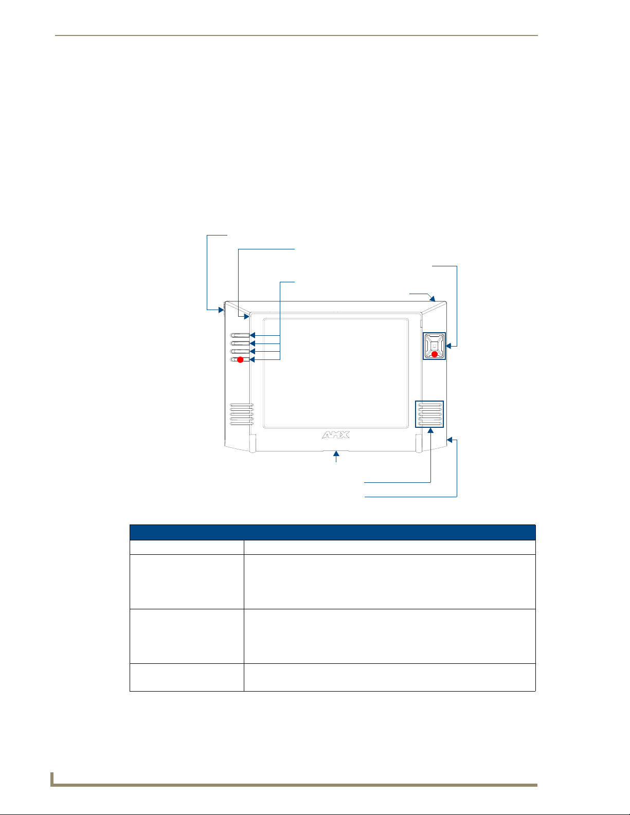
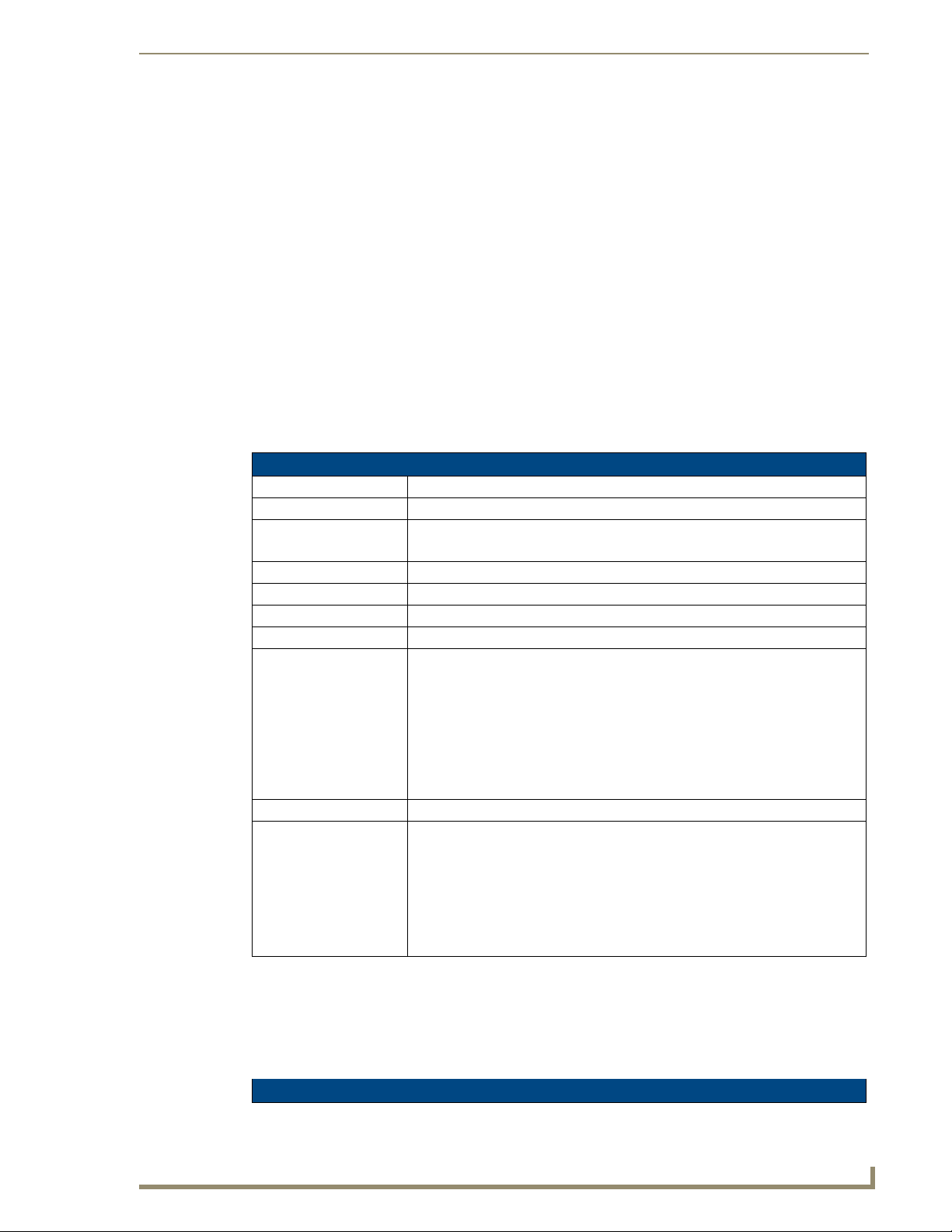
The MVP-8400i Modero Viewpoint Wireless Touch Panel (FIG. 1) is a 8.4", 802.11-based wireless
handheld G4 touch panels, pre-installed with an 802.11 Wi-Fi Interface Card to communicate with a
NetLinx Master via a standard 802.11g Wireless Access Point.
The MVP-8400i features full-duplex intercom functionality.
FIG. 1 MVP-8400i Touch Panel
MVP panels feature nine programmable external pushbuttons and two programmable LEDs,
and support AMX G4 graphics technology, making them compatible with AMX’s TPDesign4
Touch Panel Design program.
MVP panels utilize two IR frequencies (38 KHz and 455 KHz) as well as 2 additional
user-defined IR libraries, on 4 IR ports.
MVP panels feature programmable firmware that can be upgraded via either the wireless
interface card or the mini-USB port. MVP panels utilize unique firmware kit files that can be
downloaded from www.amx.com.
MVP panels support AMX Computer Control, which enables remote viewing and control of
any networked computer directly from the panel. This gives the user the ability to launch
digital music from a PC, cruise the Internet, check and respond to E-mail, open software files,
and launch applications.
MVP panels come equipped with a battery and power supply (see specifications).
MVP-8400i Modero Viewpoint Wireless Touch Panels
1
Page 12
MVP-8400i Modero Viewpoint Wireless Touch Panel With Intercom
Optional AMX accessory solutions for the MVPs include
MVP-TDS Table Top Docking Station (see the MVP-TDS Table Top Docking Station
Operation/Reference Guide for details).
MVP-WDS Wall/Flush Mount Docking Station-Black/Silver (see the MVP-WDS Wall
Docking Station Operation/Reference Guide for details).
MVP-KS Kickstand (see the MVP-KS Kickstand Operation/Reference Guide for details).
Specifications
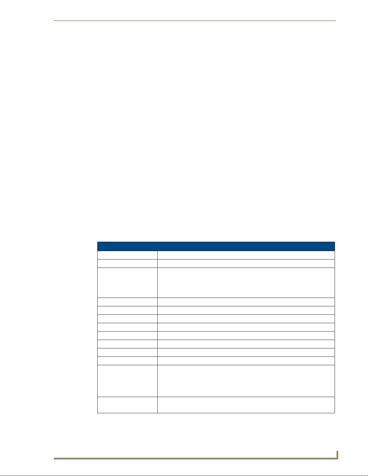
The MVP-8400i panel utilizes an 8.4" Color Active LCD to display an 800 x 600 pixel
resolution using 256K colors.
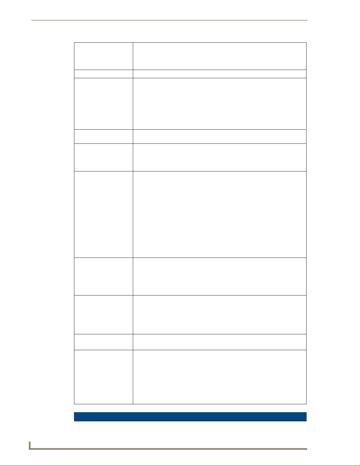
Stylus
Microphone
Directional pad w/center select button
Pushbuttons (4)
Mini-USB connector
C
Docking station interface connector
Speaker
Power connector
FIG. 2 MVP Touch Panels
C
MVP-8400i Specifications (FG5965-04)
Dimensions (HWD): 7.09" x 10.47" x 1.47" (18.00 cm x 26.60 cm x 3.73 cm)
Power Requirement
(without charging):
Power Requirement
(while charging):
Minimum power
supply required:
Panel with batteries fully charged or with no batteries:
• Constant current draw: 1.3 A @ 12 VDC
• Startup current draw: 1.9 A @ 12 VDC
• If panel is mounted onto a TDS or WDS, add 0.1 A to the above figures.
Panel while charging batteries:
• Constant current draw: 3.3 A @ 12 VDC
• Startup current draw: 3.9 A @ 12 VDC
• If panel is mounted onto a TDS or WDS, add 0.1 A to the above figures.
PS4.4 Power Supply (FG423-45)
- All MVP models are shipped with this power supply.
2
MVP-8400i Modero Viewpoint Wireless Touch Panels
Page 13

MVP-8400i Modero Viewpoint Wireless Touch Panel With Intercom
MVP-8400i Specifications (FG5965-04) (Cont.)
Power Modes: • ON: Panel is fully functional.
• STANDBY: Panel uses low power, the LCD/backlight is shutdown, LEDs still
function. Panel resumes the ON mode in ~ 1 second.
• OFF: On-board programs not running, touch screen still powered, LED not
functional. Panel resumes the ON mode in ~ 30 seconds.
Battery Duration:
(per battery)
Memory (factory default): • 128 MB SDRAM
Weight: 1.85 lbs (0.84 kg)
MVP-8400i LCD
Specifications:
Active Screen Area: • 6.71” x 5.03” (17.04cm x 12.78cm)
External Components:
Docking station interface
connector:
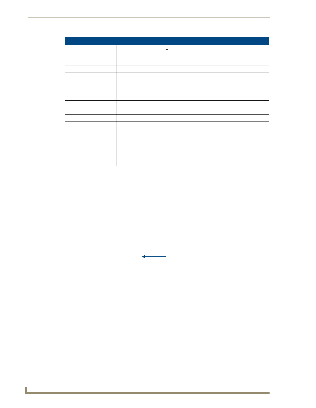
LEDs: Two sets of NetLinx programmable LEDs (supporting On, Off, and Blink).
Mini-USB connector: 5-pin mini-USB connector for programming, firmware update, and file transfer.
Power connector: • 2.1mm barrel-style power jack, for use with the included PS4.4 power supply.
Stylus slot: • Illuminated slot where the included stylus is stored, located on the left side of
External Buttons: • Nine programmable pushbuttons (four located on the left of the LCD and five
Internal Components:
Wireless Interface card: Provides 802.11 (CF Type I) wireless connectivity between the panel and a
IR Emitters: Transmit IR over 20 feet (6.10 m).
Internal speaker: Single 2 watt speaker.
Internal microphone For use with the intercom feature
Battery compartment: Houses up to 2 MVP-BP Power Packs.
• Eight hours of normal use (25% On state, 25% Standby, and 50% Off).
• Four hours of continuous use (continuous On state).
The MVP-8400i panel is shipped with two MVP-BP batteries. You must use
both batteries to obtain the duration times given above.
• 128 MB Compact Flash (upgradable to 1 GB) - factory programmed
• with 1 battery: 2.25 lbs (1.02 kg)
• with 2 batteries: 2.65 lbs (1.20 kg)
• Aspect ratio: 4 x 3
• Brightness (luminance): 180 cd/m
2
• Channel transparency: 8-bit Alpha blending
• Contrast ratio: 350:1
• Display colors: 256K colors (18-bit color depth)
• Dot/pixel pitch: 0.21 mm
• Panel type: TFT Color Active-Matrix
• Screen resolution: 800 x 600 pixels (HV) @ 60 Hz frame frequency
• Viewing angles (vertical): + 60° / - 40° (from center)
Metallic strip connector located on the bottom panel provides communication
and power between the panel and the optional docking stations.
Default blink patterns:
- Stylus LED: Blink = Batteries charging, On = Batteries charged.
- Front panel LED: Blink = Panel booting, On = Panel operating properly.
the MVP.
located on the right in a joystick configuration).
Wireless Access Point (such as the NXA-WAP200G).
MVP-8400i Modero Viewpoint Wireless Touch Panels
3
Page 14
MVP-8400i Modero Viewpoint Wireless Touch Panel With Intercom
MVP-8400i Specifications (FG5965-04) (Cont.)
Internal Components (Cont.):
Button Assignments: Button assignments can only be adjusted in TPD4 and not on the panels.
• Button channel range: 1 - 4000 button push and feedback (per address port)
• Button variable text range: 1 - 4000 (per address port)
• Button states range: 1 - 256 (General Button; 1 = Off State, 2 = On State)
• Level range: 1 - 600 (default level value 0-255, can be set up to 1-65535)
• Address port range: 1 - 100
Operating / Storage
Environment:
Certifications: • FCC Part 15 Class B and CE
Included Accessories: • MVP-BP Power Pack (FG5965-20): 2 included
Other AMX Equipment: • CB-MVPWDS Conduit Box (FG037-10)
• Operating Temperature: 0° C (32° F) to 40° C (104° F)
• Operating Humidity: 20% - 85% RH
• Storage Temperature: -20° C (-4° F) to 60° C (140° F)
• Storage Humidity: 5% - 85% RH
• IEC60950
• 80211xCF Wireless Interface Compact Flash card (Type 1) - pre-installed
• PS4.4 Power Supply (FG423-44)
•Stylus
• CC-USB (Type A) to Mini-B 5-Wire programming cable (FG10-5965)
• MVP-BP Power Pack (additional/spare) (FG5965-20)
• MVP-KS Kickstand (FG5965-12)
• MVP-STYLUS three pack (FG5965-30)
• MVP-TDS Table Top Docking Station (FG5965-10)
• MVP-WDS Wall/Flush Mount Docking Station:
Black (FG5965-11) / Silver (FG5965-21)
• MVP-WDS-SK Silver Conversion Kit for MVP-WDS (FG5965-22)
• NXA-WC80211GCF 802.11g Wireless Compact Flash Card Upgrade Kit
(FG2255-07)
• Upgrade Compact Flash (factory programmed with firmware):
NXA-84ICF256M, 256 MB COMPACT FLASH CARD (FG2116-70)
NXA-84ICF512M, 512 MB COMPACT FLASH CARD (FG2116-71)
NXA-84ICF1G, 1 GB COMPACT FLASH CARD (FG2116-72)
4
MVP-8400i Modero Viewpoint Wireless Touch Panels
Page 15
MVP-BP Power Pack
Overview
The MVP-BP Power Pack (FG5965-20) is a rechargeable Lithium-Ion battery used to provide power to
the MVP touch panels. Two MVP-BPs are included with each MVP-8400i touch panel.
FIG. 3 MVP-BP Power Pack
MVP-BP Power Pack
MVP-BPs can be charged with either a Table Top Docking Station (MVP-TDS), Wall/Flush Mount
Docking Station (MVP-WDS), or MVP panel itself. Extra MVP-BP Power Packs can be purchased
separately.
MVP-BP Specifications
MVP-BP Specifications
Dimensions (HWD): 0.48" x 1.52" x 8.65" (1.23 cm x 3.86 cm x 21.97 cm)
Power (Voltage): 7.2 Volts (nominal)
Weight: 0.40 lbs (0.18 kg)
Charge Capacity: 3600mAh
Operating/Storage Environments: • Operating Temperature: 0° C (32° F) to 40° C (104° F)
• Operating Humidity: 20% - 85% RH
• Storage Temperature: -20° C (-4° F) to 60° C (140° F)
• Storage Humidity: 5% - 85% RH
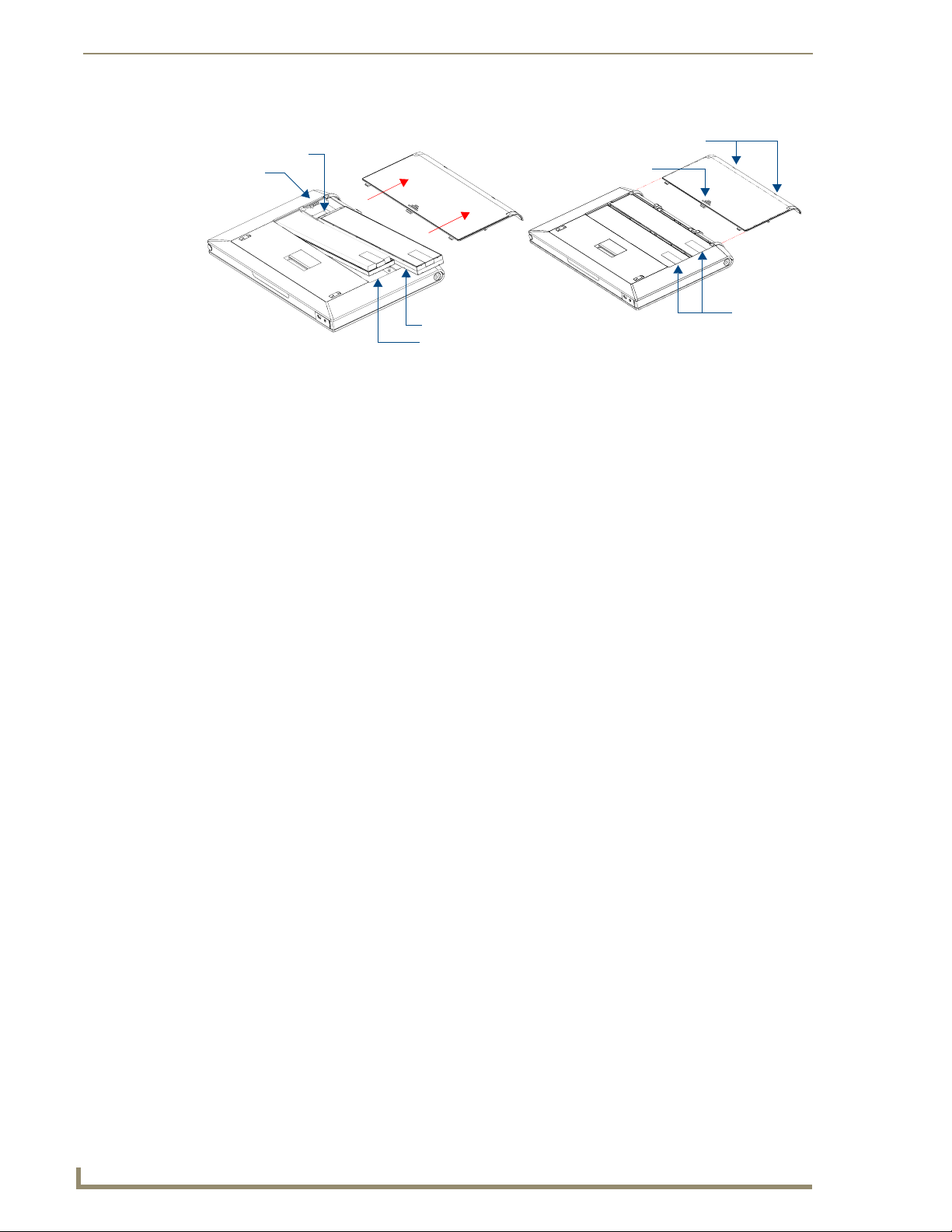
Installing MVP-BP Batteries
1. Disconnect any cables, and place the MVP face down to expose the battery compartment.
2. Press down on the traction grooves to slide the battery compartment cover (away from the metal
plate), to open the battery compartment.
3. Insert the MVP-BP(s) so that the connector makes contact with the battery pins at the end of the
battery slot as shown in
FIG. 4.
MVP-8400i Modero Viewpoint Wireless Touch Panels
5
Page 16
MVP-BP Power Pack
Battery connector
Battery Compartment Cover
Battery pins
Battery slot 2
Battery slot 1
FIG. 4 Installing MVP-BP batteries into the MVP battery slots
Alignment Guide hole openings
Traction Grooves
Battery
Removal
Straps
If you are only using one battery, use Battery Slot #1.
4. To replace the battery compartment cover, use the alignment guide holes to align the cover with the
edges of the battery compartment, and slide it back into place until it snaps shut.
6
MVP-8400i Modero Viewpoint Wireless Touch Panels
Page 17
NXA-CFSP Compact Flash
Overview
Every MVP panel is shipped with a 128 MB Compact Flash card.
Compact Flash Card - Security
All security user names and passwords (for the docking station) are stored in the Compact Flash card.
After installing the Compact Flash card upgrade, all security user names and passwords need to be reentered to enable security. For this reason, it is recommended that you upgrade the card prior to setting
up the security information for the docking station.
The NXA-CFSP Compact Flash card is factory programmed with panel firmware and can be upgraded
up to 1GB:
Optional Compact Flash Upgrades
NXA-84ICF256M, 256 MB COMPACT FLASH CARD (FG2116-70)
NXA-84ICF512M, 512 MB COMPACT FLASH CARD (FG2116-71)
NXA-84ICF1G, 1 GB COMPACT FLASH CARD (FG2116-72)
NXA-CFSP Compact Flash
Installing the NXA-CFSP Compact Flash Card
Batteries should be removed prior to upgrading the Compact Flash card.
Accessing the MVP’s Internal Components
1. Remove all connectors, remove power and remove batteries.
2. Remove the two housing screws (FIG. 5).
MVP-8400i Modero Viewpoint Wireless Touch Panels
7
Page 18
NXA-CFSP Compact Flash
Battery Compartment cover
Housing screws
Bottom rim of outer
housing
Rear outer housing
Trim fits inside
the grooves around
the edges of the panel
Circuit board
housing
attachment
locations (4)
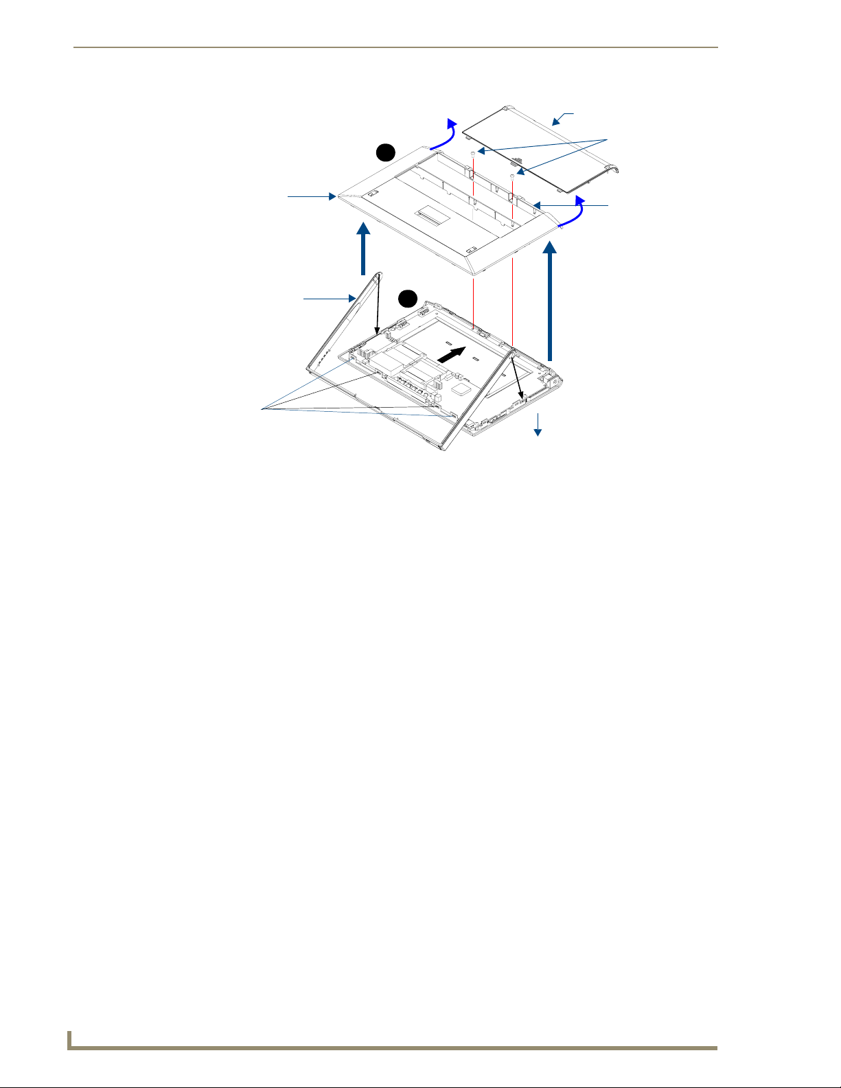
FIG. 5 Removing the MVP enclosure (housing)
B
A
Panel
3. Grasp the bottom rim of the rear housing just above the MVP interface connector, and carefully pull
the bottom rim away from the IR Emitter and up, to expose the internal components.
4. Remove the trim from the top rim of the circuit board (FIG. 5).
Removing the Installed Card
1. Discharge any static electricity from your body by touching a grounded metal object and then locate
the card slot on the main circuit board (
FIG. 6).
2. Place the circuit board on a flat level surface so that the IR Emitters are pointing away from you
FIG. 6).
(
3. Insert the tip of a grounded flat-head screwdriver into one of the card removal grooves (located on
either side of the existing card), and gently pry it out of the slot (
FIG. 7). Repeat this process on the
opposite card removal groove. This alternating action causes the card to "wiggle" away from the
on-board connector pins.
4. Slip your finger into the gap between the card and the circuit board and firmly grab the card by its
sides, then carefully pull it up and out of the slot. An angular removal of the card is required because
one of the housing’s latch attachments blocks the slot opening.
use care when pulling up on the card.
Installing the Compact Flash Upgrade Card
1. Discharge any static electricity from your body by touching a grounded metal object and then locate
the memory card slot on the main board (A in
FIG. 6).
8
MVP-8400i Modero Viewpoint Wireless Touch Panels
Page 19

NXA-CFSP Compact Flash
Card removal grooves
IR Emitters
Compact Flash
card
A B
FIG. 6 Location and orientation of the Compact Flash cards (both MVP panels)
Internal circuit board
(top view - detail)
Wireless Interface
card
2. Place the circuit board on a flat level surface so that the IR Emitters are pointing away from you
FIG. 6).
(
3. Insert the tip of a grounded flat-head screwdriver into one of the card removal grooves (located on
either side of the existing Compact Flash card), and gently pry it out of the slot (
FIG. 7). Repeat this
process on the opposite card removal groove. This alternating action causes the pre-existing card to
"wiggle" away from the on-board connector pins.
4. Slip your finger into the opening (between the connector pins and the card resulting from step 3)
and push the card out.
5. Finish the process by firmly gripping the exposed sides of the card and pulling it out (FIG. 7). USE
CARE WHEN HANDLING THE CARD.
Card removal
grooves
On-board Compact
Flash connector (with pins)
Insert with arrow
facing towards the pins
Connector opening
FIG. 7 Removing/installing a Compact Flash Memory card
6. Insert the new card firmly into the slot opening connector (FIG. 7) until the contact pins are
completely inside the card and securely attached to the pin sockets.
Any new Compact Flash card upgrade is detected by the panel only after the unit
cycles power.
MVP-8400i Modero Viewpoint Wireless Touch Panels
9
Page 20

NXA-CFSP Compact Flash
10
MVP-8400i Modero Viewpoint Wireless Touch Panels
Page 21
Wireless Interface Cards
802.11b Wireless Interface Card
MVP panels can connect to a wireless network using the 802.11b Wireless Interface Card (70-5965-02),
pre-installed in MVP touch panel models. The 802.11b Wireless Interface Card is a 2.4 GHz Direct
Sequence Spread Spectrum (DSSS) 802.11b 11M wireless PC card, with detachable antenna.
FIG. 8 802.11b Wireless Interface Card
The wireless interface card works with 802.11b/g Wireless Access Points, such as the NXA-WAP200G.
Wireless Interface Cards
The NXA-WAP200G uses a default SSID of AMX.
Follow your particular WAP’s instruction manual for setup procedures.
Specifications
802.11b Wireless Interface Card Specifications
Dimensions (HWD): • 2.07" x 1.68" x 0.21" (52.56 mm x 42.80 mm x 5.57 mm)
Weight: • 13.61 grams (0.030 lbs)
Features: • Wired Equivalent Privacy (WEP) 64-bit and 128-bit data encryption
• Diversity Antenna Connectors automatically select the best available signal
• Supports infrastructure (communications to wired networks via Access Points),
and roaming (standard IEEE 802.11b compliant)
Antenna: • 2, Ceramic (Diversity Supported)
Host Interface: • Compact Flash Type I
Interoperability: • Interoperable with Wi-Fi (WECA) certified products
LED Indicators: • Power / Link activity
Modulation: • DSSS, DBSK, DQSK, CCK
Network Standard: • IEEE 802.11b
Number of Channels: •14
Operating Voltage: • 5 / 3.3 V
Operating Channels: • 11 Channels (USA, Canada)
• 13 Channels (Europe)
• 14 Channels (Japan)
• 4 Channels (France)
Operating Environment: • Temperature: 0°C ~ 70°C (non-operating) and -15 ~ 80°C (storage)
• Humidity (non-condensing): 5% ~ 95% RH
MVP-7500/8400 Modero Viewpoint Wireless Touch Panels
11
Page 22
Wireless Interface Cards
802.11b Wireless Interface Card Specifications (Cont.)
Power Consumption: • TX power consumption: < 265 mA
Radio Data Rate: • 1Mbps, 2Mbps, 5.5Mbps, 11Mbps, Auto Rate
Receive Sensitivity: • @PER < 8%
RF Output Power: • 15 dBm +/- 1 dBm
Security: • WEP 64,128 bit, WPA/TKIP
Wireless Restrictions: • In R&TTE countries, such as France, the 802.11g frequency band is restricted to
Certifications: • FCC (United States)
• RX power consumption: < 165 mA
• Sleep Mode: 2 mA - 15 mA
11 Mbps: -83 dBm (max)
5.5 Mbps: -86 dBm (max)
2 Mbps: -89 dBm (max)
1 Mbps: -92 dBm (max)
• Channels 1 - 11 (North America)
2454 - 2483.5 MHz (2.4 - 2.4835 GHz) and a max power output of
100 mW EIRP outdoor.
• IC (Canada)
• CE (Europe)
• TELEC (Japan)
The only time the wireless card should be removed is in case of failure or when
upgrading to the 802.11g Wi-Fi card.
NXA-WC80211GCF 802.11g Wireless Interface Card
Optionally, MVP panels can be upgraded with the field-installable 802.11g Wi-Fi card (FG2255-07),
purchased separately as a Wi-Fi Upgrade Kit.
FIG. 9 NXA-WC80211GCF 802.11g wireless card
The NXA-WC80211GCF is a 2.4 GHz Wi-Fi LAN CF Card which upgrades a Modero panel’s RF
capabilities from 802.11b to 802.11g. This card provides enhanced range and throughput, wireless
encryption and data security (WPA and WPA2 and WEP) in Compact Flash Type I form factor.
The NXA-WC80211GCF incorporates DSSS and OFDM radio technology and operates at ISM
frequency bands of 2.4 GHz, while providing data transfer speeds of up to 54Mbps.
Other features include:
Support for IEEE 802.11b and 802.11g
Supports Advanced Encryption Standard (AES) at 128-bit.
PIFA antenna
12
MVP-7500/8400 Modero Viewpoint Wireless Touch Panels
Page 23
Wireless Interface Cards
Supports authentication methods such as: EAP-FAST, EAP-LEAP, EAP-PEAP, EAP-TLS,
and EAP-TTLS
Supports Wired Equivalent Privacy (WEP) 64-bit and 128-bit data encryption (known to the
on-board firmware as Static WEP)
The NXA-WC80211GCF is backwards compatible with 802.11b networks.
To fully utilize wireless security features, this card must be used in tandem with the
latest Modero firmware upgrade available at www.amx.com.
This upgrade kit requires that pre-existing panels first be removed from their current location (surface,
wall or docking station) before an installer can access the internal circuit boards and upgrade a preexisting 802.11b wireless CF card.
MVP panels require the use of a cardboard cutout (Mounting Template) to properly position the metal
antenna plate onto the inner surface of the unit’s rear plastic housing.
Specifications
NXA-WC80211GCF Specifications
Dimensions (HWD): • 0.22" x 1.68" x 2.40" (5.6 mm x 42.80 mm x 61.0 mm)
Weight: • 19.50 grams (0.043 lbs)
Description: • Wireless LAN Compact Flash Card with external PIFA antenna.
• Features enterprise-class security such as WPA and WPA2 security.
•
Antenna Type: • External PIFA antenna (factory-installed)
Bus Interface: • Compact Flash Type I
Certifications: • FCC Part 15 Class B, CE, IC, TELEC, and Wi-Fi
Media Access Control
Techniques:
Network Architecture: • Infrastructure mode (Client-to-Access Point)
Operating Channels: • Using 802.11b & g communication:
• Using 802.11b DSSS communication:
DBPSK @ 1 Mbps
DQPSK @ 2 Mbps
CCK @ 5.5 Mbps
• Using 802.11g OFDM communication:
BPSK @ 6 and 9 Mbps
QPSK @ 12 and 18 Mbps
16-QAM @ 24 and 36 Mbps
64-QAM @ 48 and 54 Mbps
- 04: (Ch 10 - 13) - France
- 11: (Ch 1 - 11) - North America
- 13: (Ch 1 - 13) - Europe ETSI
- 13: (Ch 1 - 13) - Japan (802.11g)
- 14: (Ch 1 - 14) - Japan (802.11b)
Note: To alter the card’s default country code (North America), contact an AMX
Technical Support representative for detailed procedures and information.
NXA-WC80211GCF Specifications (Cont.)
MVP-7500/8400 Modero Viewpoint Wireless Touch Panels
13
Page 24
Wireless Interface Cards
Operating Environment: • Temperature: 0°C ~ 45°C (32°F to 113°F) (operating) and
Operating Voltage: • 3.3V + 5% I/O supply voltage
Power Consumption: • @ 802.11b communication:
Radio Data Rate: • 802.11g compliant: 1, 2, 5.5, 11 (DSSS/CCK); 6, 9, 12, 18, 24, 36, 48, and 54
Radio Technology: • Using 802.11b communication: DSSS (Direct Sequence Spread Spectrum)/CCK
Receiver Sensitivity: • Using 802.11b communication @ FER<8%:
RF Frequency Ranges: • Using 802.11b & g communication:
Standard Conformance: • IEEE 802.11b
Transmit Output Power: • 802.11b communication: 12 +-1 dBm (1, 2, 5.5, 11 Mbps)
Wireless LAN Security: • EAP-FAST
-20°C ~ 70°C (-4°F to 158°F) (storage)
• Humidity: (non-condensing) 5% ~ 90% RH (operating) and
(non-condensing) 5% ~ 95% RH (storage)
- RX: 270 mA
- TX: 435 mA
- Standby: 240 mA
• @ 802.11g communication:
- RX: 270 mA
- TX: 460 mA
- Standby: 240 mA
(OFDM) Mbps data rates
(Complementary Code Keying)
• Using 802.11g communication: DSSS/CCK, OFDM (Orthogonal Frequency
Division Multiplexing
1 Mbps: -94 dBm (max)
2 Mbps: -93 dBm (max)
5.5 Mbps: -92 dBm (max)
11 Mbps: -90 dBm (max)
• Using 802.11g communication @ PER <10%:
6 Mbps: -87 dBm (max)
9 Mbps: -86 dBm (max)
12 Mbps: -86 dBm (max)
18 Mbps: -84 dBm (max)
24 Mbps: -82 dBm (max)
36 Mbps: -78 dBm (max)
48 Mbps: -74 dBm (max)
54 Mbps: -72 dBm (max)
Europe ETSI: 2.412 ~ 2.472 GHz
France: 2.457 ~ 2.472 GHz
Japan (802.11b): 2.412 ~ 2.484 GHz
Japan (802.11g): 2.412 ~ 2.472 GHz
North America: 2.412 ~ 2.462 GHz
• IEEE 802.11g
• IEEE 802.11e
• IEEE 802.11i
• Wi-Fi (WPA and WPA2)
• 802.11g communication: 12 +-1 dBm (6, 9, 12, 18, 24, 36, 48, and 54 Mbps)
• EAP-LEAP
• EAP-PEAP
• EAP-TLS
• EAP-TTLS
• WEP 64 & 128
•WPA-PSK
14
NXA-WC80211GCF Specifications (Cont.)
MVP-7500/8400 Modero Viewpoint Wireless Touch Panels
Page 25

Wireless Interface Cards
Touch Panel
Compatibility:
Included Accessories: • Double-sided adhesive tape
• MVP-7500 (FG5965-01)
• MVP-8400 (FG5965-02)
•NXD-CV10 (FG2259-02)
• NXT-CV10 (FG2259-01/03)
•NXD-CV7 (FG2258-02)
• NXT-CV7 (FG2258-01)
• Mounting Template cutout (62-2255-04)
• NXA-WC80211GCF Quick Start Guide
• Two Alcohol cleaning pads
• Wireless CF card with wireless antenna
Installing the 802.11g Card and Antenna
Upgrading the cards on an MVP involves opening the panel enclosure, removing the existing card,
replacing it with the upgrade, and then closing the panel enclosure, as described below.
Firmware Requirements
The NXA-WC80211GCF requires panel firmware version 5965-02. This firmware supports backwards
compatibility with 802.11b cards, and security protocols for the NXA-WC80211GCF.
Before installing the NXA-WC80211GCF, upload the latest panel-specific kit file to your MVP.
Access the MVP’s Internal Components
Refer to the Accessing the MVP’s Internal Components section on page 7 for details.
Removing the Installed Card
Refer to the Removing the Installed Card section on page 8 for details.
Preparing the MVP’s Rear Housing
1. Flip over the MVP’s rear housing so that the internal support structures are visible, and lay it
directly in front of the circuit board such that the battery compartment is furthest away from you.
This placement provides contact of both top rims (
FIG. 10).
2. Use an alcohol pad (included) to clean both the rear housing’s inner surface (bottom right corner)
and the underside of the terminal antenna’s metal plate (
FIG. 9). These surfaces must be properly
cleaned to provide good adhesion for the later installation of the antenna.
3. Place the included Mounting Template along the bottom right corner of the rear housing (FIG. 10).
Use the housing’s inner supports to position the template properly.
MVP-7500/8400 Modero Viewpoint Wireless Touch Panels
15
Page 26

Wireless Interface Cards
Mounting Template
clean
this
area
Wireless Card Slot
FIG. 10 Installing the Mounting Template
Inner supports
Installing the NXA-WC80211GCF
1. Grip the sides of the NXA-WC80211GCF and insert it into the slot opening at a downward angle
until the contact pins are securely attached to the pin sockets.
2. Carefully peel off one side of the included double-sided tape and adhere the adhesive side to the
surface of the antenna’s metal plate.
3. Align the double-sided tape to the surface of the terminal antenna’s metal plate, in order to later
secure the antenna within the pre-defined installation area outlined by the included Mounting
Template.
4. Locate the T-shaped opening on the left of the cutout and make sure the antenna wire is located
along the left side of the cutout (FIG. 4).
16
FIG. 11 Adhering the antenna plate to the MVP outer housing
MVP-7500/8400 Modero Viewpoint Wireless Touch Panels
Page 27

Wireless Interface Cards
5. Grip the antenna by its sides and carefully peel-off the remaining protective film on the double-
sided tape.
6. Align the antenna into the long vertical groove in the cutout and firmly adhere it to the inner surface
of the housing. Make sure the wire is threaded along the left side of the cutout, this helps in the
removal of the cutout.
7. With the antenna now securely attached to the MVP’s inner housing, remove the cutout by carefully
pulling up on the cutout and threading the antenna wire through the
T-shaped opening.
Closing and Securing the MVP Enclosure
Once the card has been installed, close and re-secure the outer housing:
1. Reinstall the dark grey trim along the top rim of the board (A in FIG. 12).
2. While angling the top rim of the MVP’s rear outer housing (B in FIG. 12) down toward the IR
Emitters, insert the four outer housing latches into their corresponding attachment locations along
the top rim of the MVP panel (two on either side of the IR Emitters).
Outer housing latches (4)
B
A
4 Outer housing latch
attachment locations
FIG. 12 Outer housing latch attachment locations
3. While firmly holding the top rims together, gently press down on the bottom ridge of the outer
housing (at the latch locations) and verify that each housing latch fits within its corresponding
attachment location on the board. When done, complete the insertion of the remaining housing
latches.
4. Verify that the notches along the bottom of the plastic battery slot separator strip also fit into the
three provided alignment holes on the circuit board.
5. Firmly press down around the entire rim of the outer housing to snap the cover back into place.
Be careful not to pinch the antenna wire in the housing.
6. Use a grounded Phillips-head screwdriver to insert and resecure the two housing screws removed in
Step 1.
7. Insert any available batteries back into the battery compartment.
MVP-7500/8400 Modero Viewpoint Wireless Touch Panels
17
Page 28

Wireless Interface Cards
8. Grab the battery cover and align it over the edges of the battery compartment. Apply downward
pressure to the traction grooves on the Battery Compartment cover and slide it back towards the
metal plate to reinstall the cover.
18
MVP-7500/8400 Modero Viewpoint Wireless Touch Panels
Page 29
Configuring Communications
Communication between the MVP and the Master consists of using either Wireless Ethernet (DHCP,
Static IP) or USB. References to Ethernet in this manual focus on the use of Wireless Ethernet via the
MVP’s WiFi Card.
Configuring Communications
Before commencing, verify you are using the latest NetLinx Master and
Modero panel-specific firmware. Verify you are using the latest versions of AMX’s
NetLinx Studio and TPDesign4 programs.
USB input devices must be plugged into the USB connectors on the docking stations
before the units are powered-up.
Modero Setup and System Settings
AMX Modero panels feature on-board Setup pages. Use the options in the Setup pages to access panel
information and make various configuration changes.
Accessing the Setup and Protected Setup Pages
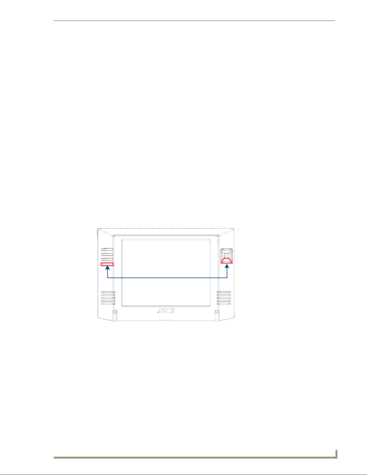
1. Press down and hold both the bottom, left pushbutton and down on the directional pad
simultaneously for 3-5 seconds. This opens the Setup page.
Setup Page Access buttons:
Press and hold simultaneously for
3-5 seconds to access the Setup pages
Press and hold for 6 seconds
to access the Calibration page.
FIG. 13 Setup Page Access buttons
2. Press the Protected Setup button. This invokes a keypad for entry of the password to allow access to
the Protected Setup page. Enter 1988 (the default password), and press Done to proceed.
MVP-8400i Modero Viewpoint Wireless Touch Panels
19
Page 30

Configuring Communications
Setting the Panel’s Device Number
In the Protected Setup page:
1. Press the Device Number field to open the Device Number keypad (FIG. 14).
FIG. 14 Protected Setup page
Enter a unique Device Number assignment for the panel, and press Done to return to the Protected
Setup page. The Device Number range is 1 - 32000, the default is 10001.
2. Press Reboot to reboot the panel, and apply the new Device Number.
Wireless Settings Page - Wireless Access Overview
Hot Swapping
Hot swapping is not an issue on these panels as the card is installed within the unit and cannot be
removed without first removing the housing.
In the case of DHCP, there must be a DHCP server accessible before the fields are populated.
If the SSID (Network Name) and WEP fields have not previously been configured, the
Wireless Settings page will not work until the panel is rebooted.
Before selecting Ethernet as the Master Connection Type you must setup the parameters of the wireless
card. The Wireless Access Point communication parameters must match those of the pre-installed
wireless CF card inside the MVP.
The MVP touch panels allow users to connect to a wireless network through their use of the
pre-installed AMX 802.11g wireless interface card to communicate with a Wireless Access Point (WAP)
such as the NXA-WAP200G). The WAP communication parameters must match those of the
pre-installed wireless interface card installed within the panel. This internal card transmits data
wirelessly using the 802.11x signals at 2.4 GHz. For a more detailed explanation of the new security and
encryption technology, refer to the section of the document entitled:
Appendix B - Wireless
Te ch no l og y section on page 169.
For more information on utilizing the AMX Certificate Upload Utility in conjunction with the EAP
security, refer to the section of the document entitled:
Appendix B - Wireless Technology section on
page 169.
20
MVP-8400i Modero Viewpoint Wireless Touch Panels
Page 31
Configuring Communications
Configuring a Wireless Network Access
When working with a wireless card, the first step is to configure wireless communication parameters
within the Wireless Settings page. This page only configures the card to communicate to a target WAP
(such as the NXA-WAP200G), it is still necessary to tell the panel which Master it should be
communicating with. This "pointing to a Master" is done via the System Settings page where you
configure the IP Address, System Number and Username/Password information assigned to the target
Master.
Step 1: Configure the Panel’s Wireless IP Settings
The first step to successfully setting up your internal wireless card is to configure the IP Settings section
on the Wireless Settings page. The section configures the communication parameters from the MVP
panel to the web.
Wireless communication using a DHCP Address
In the Protected Setup page:
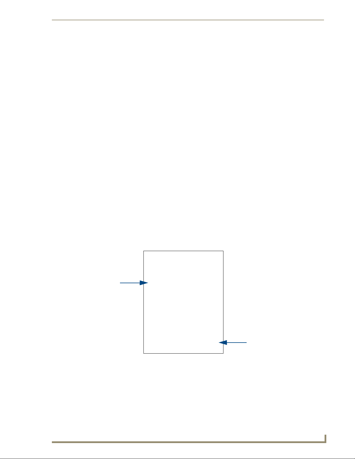
1. Select Wireless Settings. Wireless communication is set within the IP Settings section of this page
FIG. 15).
(
2. Toggle the DHCP/Static field (from the IP Settings section) until the choice cycles to DHCP. This
action causes all fields in the IP Settings section (other than Host Name) to be greyed-out.
Do not alter any of these remaining greyed-out fields in the IP Settings section. Once the panel is
rebooted, these values are obtained by the unit and displayed in the DNS fields after power-up.
DHCP will register the unique MAC Address (factory assigned) on the panel and
once the communication setup process is complete, assign IP Address, Subnet
Mask, and Gateway values from the DHCP Server.
3. Press the optional Host Name field to open a Keyboard and enter the Host Name information.
Modero
connection
IP info.
Wireless Access Point
Site Survey Button
FIG. 15 Wireless Settings page (IP Settings section)
4. Press Done after you are finished assigning the alpha-numeric string of the host name.
5. Do not alter any of these remaining greyed-out fields in the IP Settings section. Once the panel is
rebooted, these values are obtained by the unit and displayed in the DNS fields after power-up.
MVP-8400i Modero Viewpoint Wireless Touch Panels
21
Page 32

Configuring Communications
This information can be found in either the Workspace - System name > Define
Device section of your code (that defines the properties for your panel), or in the
Device Addressing/Network Addresses section of the Tools > NetLinx Diagnostics
dialog.
6. Setup the security and communication parameters between the wireless card and the target WAP by
configuring the Wireless Settings section on this page. Refer to
Wireless Security Settings section on page 24 for detailed procedures to setup either a secure or
unsecure connection.
Wireless communication using a Static IP Address
In the Protected Setup page:
1. Press the Wireless Settings button (located on the lower-left) to open the Wireless Settings page.
Wireless communication is set within the IP Settings section of this page (
Check with your System Administrator for a pre-reserved Static IP Address assigned
to the panel. This address must be obtained before Static assignment of the panel
continues.
2. Toggle the DHCP/Static field (from the IP Settings section) until the choice cycles to Static.
The IP Address, Subnet Mask, and Gateway fields then become user-editable (red).
3. Press the IP Address field to open a Keyboard and enter the Static IP Address (provided by your
System Administrator).
4. Press Done after you are finished entering the IP information.
5. Repeat the same process for the Subnet Mask and Gateway fields.
6. Press the optional Host Name field to open the Keyboard and enter the Host Name information.
7. Press Done after you are finished assigning the alpha-numeric string of the host name.
8. Press the Primary DNS field to open a Keyboard, enter the Primary DNS Address (provided by your
System Administrator) and press Done when compete. Repeat this process for the Secondary DNS
field.
9. Press the Domain field to open a Keyboard, enter the resolvable domain Address (this is provided
by your System Administrator and equates to a unique Internet name for the panel), and press Done
when complete.
10. Setup the security and communication parameters between the wireless card and the target WAP by
configuring the Wireless Settings section on this page. Refer to the following section for detailed
procedures to setup either a secure or unsecure connection.
Step 2: Configure the Card’s
FIG. 15).
22
Using the Site Survey tool
This tool allows a user to "sniff-out" all transmitting Wireless Access Points within the detection range
of the internal NXA-WC80211GCF. Once pressed, the panel displays the Site Survey page which
contains categories such as:
Network Name (SSID) - Wireless Access Point names
Channel (RF) - Channel currently being used by the WAP (Wireless Access Point)
Security Type (if detectable - such as WEP, OPEN and UNKNOWN) - security protocol
enabled on the WAP
Signal Strength - None, Poor, Fair, Good, Very Good, and Excellent
MAC Address - Unique identification of the transmitting Access Point
MVP-8400i Modero Viewpoint Wireless Touch Panels
Page 33

Configuring Communications
Indicates the currently
active column and the order
in which the data is being sorted (Descending order shown)
Indicates a selected AP
FIG. 16 Site Survey page
In the Protected Setup page:
1. Press the Wireless Settings button (located on the lower-left) to open the Wireless Settings page.
2. Navigate to the Access Point MAC Address section of this page and press the on-screen
Site Survey button. This action launches the Site Survey page which displays a listing of all
detected WAPs in the communication range of the internal card.
The card scans its environment every four seconds and adds any new WAPs found to the list.
Every scan cycle updates the signal strength field.
Access points are tracked by MAC Address.
If the WAP’s SSID is set as a blank, then N/A is displayed within the SSID field.
If the WAP’s SSID is hidden (not broadcast) it will not show up on the site survey
screen but it can still be configured via the SSID field on the specified security mode
screen.
If a WAP is displayed in the list is not detected for 10 scans in a row it is then
removed from the screen. In this way, a user can walk around a building and see
access points come and go as they move in and out of range.
3. Sort the information provided on this page by pressing on a column name and toggling the direction
of the adjacent arrow.
Up arrow - indicates that the information is being sorted in a Ascending order.
SSID (A to Z), Channel (1 to 14), Security (Unknown to WEP), Signal (None to
Excellent). The firmware considers the following to be the security order from least
secure to most secure: Open, WEP, WPA, WPA2, and Unknown.
Down arrow - indicates that the information is being sorted in a Descending order.
SSID (Z to A), Channel (11 to 6), Security (WEP to Unknown), Signal (Excellent
to None)
If the panel detects more than 10 WAPs, the Up/Down arrows at the far right side of
the page become active (blue) and allow the user to scroll through the list of entries.
MVP-8400i Modero Viewpoint Wireless Touch Panels
23
Page 34

Configuring Communications
4. Select a desired Access Point by touching the corresponding row. The up arrow and down arrow
will be grayed out if there are ten or less access points detected. If there are more, then they will be
enabled as appropriate so that the user can scroll through the list.
5. With the desired WAP selected and highlighted, click the Connect button to be directed to the
selected security mode’s Settings page with the SSID field filled in. You can then either Cancel the
operation or fill in any necessary information fields and then click Save.
If you select an Open, WEP, and WPA-PSK Access Point and then click Connect, you will be flipped
to the corresponding Settings page. For any other security mode, if you click Connect you will only
return to the previous page without any information being pre-filled out for you.
Step 2: Configure the Card’s Wireless Security Settings
The second step to successfully setting up your wireless card is to configure the Wireless Settings section
of the Wireless Settings page. This section configures both the communication and security parameters
from the internal wireless card to the WAP. The procedures outlined within the following sections use
an 802.11g card to configure a common security configuration to a target WAP.
Refer to either the Wireless Settings Page section on page 68 or the Appendix B - Wireless
Te ch no l og y section on page 169 for more information on the other security methods.
Once you have set up the wireless card parameters, you must configure the communication parameters
for the target Master; see
In an Open security mode, when a target WAP is selected and the connect to, the SSID name
of the selected WAP is saved for the open security mode.
In a Static WEP security mode, when a WEP Access Point is selected and then connected to,
the user is then redirected back to the Static WEP security screen where the SSID field is
already filled out and the user is only required to enter in the remaining WEP key settings.
A similar process occurs for WPA-PSK access points. For any other case, the firmware
switches back to the previous page and security and connection parameters must be entered in
as normal.
Step 3: Choose a Master Connection Mode section on page 31.
24
MVP-8400i Modero Viewpoint Wireless Touch Panels
Page 35

Configuring Communications
Configuring the Modero’s wireless card for unsecured access to a WAP200G
In the Protected Setup page:
1. Press the Wireless Settings button (located on the lower-left) to open the Wireless Settings page.
MVP
connection
IP info.
FIG. 17 Wireless Settings page (showing a sample unsecured configuration)
Wireless
card security settings
2. Enter the SSID information by either:
Automatically having it filled in by pressing the Site Survey button and from the Site Survey
page, choosing an Open WAP from within the Site Survey page and then pressing the
Connect button.
FIG. 18 Site Survey of available WAPS (Unsecured WAP shown selected)
Manually entering the SSID information into their appropriate fields by following steps 7
thru 9.
3. From within the Wireless Security section, press the Open (Clear Text) button to open the Open
(Clear Text) Settings dialog (
methodology but does require that an SSID (alpha-numeric) be entered. Using this method causes
network packets to be sent out as unencrypted text.
MVP-8400i Modero Viewpoint Wireless Touch Panels
Select an OPEN
(unsecured) WAP
Connecting to the
WAP begins the
communication
FIG. 19). An Open security method does not utilize any encryption
25
Page 36

Configuring Communications
FIG. 19 Wireless Settings page - Open (Clear Text) security method
4. Press the red SSID field (FIG. 19) to display an on-screen Network Name (SSID) keyboard.
5. In this keyboard, enter the SSID name used on your target Wireless Access Point (case sensitive).
6. Click Done when you’ve completed typing in the information.
7. From the Open (Clear Text) Settings page (FIG. 19), press the Save button to incorporate your new
information into the panel and begin the communication process.
8. Verify the fields in the IP Settings section have been properly configured. Refer to Step 1: Configure
the Panel’s Wireless IP Settings section on page 21 for detailed information.
9. Press the Back button to return to the Protected Setup page and press the on-screen Reboot button
to both save any changes and restart the panel. Remember that you will need to navigate to the
System Settings page and configure the connection to a target Master.
10. After the panel restarts, return to the Wireless Settings page’s RF Link Info section and verify the
Link Quality and Signal Strength:
Required Information:
- SSID (Network Name used by the Target WAP)
By default, this field displays the
SSID - AMX
The card should be given the SSID used by the target WAP. If this field is left blank, the unit
will attempt to connect to the first available WAP. By default, all WAP200Gs use AMX as
their assigned SSID value.
One of the most common problems associated with connection to a WAP arise because the
SSID was not entered properly. You must maintain the same case when entering the SSID
information. ABC is not the same as Abc.
The descriptions are: None, Poor, Fair, Good, Ver y Go o d , and Excellent (FIG. 17).
26
The signal strength field should provide some descriptive text regarding the strength
of the connection to a Wireless Access Point. If there is no signal or no IP Address
displayed; configuration of your network could be required.
MVP-8400i Modero Viewpoint Wireless Touch Panels
Page 37

Configuring Communications
Configuring the Modero’s wireless card for secured access to a WAP200G
After logging into the WAP200G, the default Status page appears within the web browser. These
read-only values are "pulled" from some of the other user-configurable Configuration Utility pages. By
default, wireless Modero panels are configured for unsecured communication to a Wireless Access
Point. To properly setup both the WAP200G and panel for secure communication, you must first prepare
the Modero panel and then use the information given to fill out the fields within the WAP’s
browser-based Basic Wireless Configuration page.
Since the code key generator on Modero panels use the same key generation formula, all panels will
generate identical keys for the same Passphrase. The generators used on WAPs will not produce the same
key as the Modero generator even if you use the same Passphrase. For this reason, we recommend
FIRST creating the Current Key on the Modero and then entering that information into the
appropriate NXA-WAP200G fields.
Automatically set SSID
In the Protected Setup page:
1. Select Wireless Settings.
2. Press the Site Survey button.
3. Select a WEP secured WAP from within the Site Survey page, and press the Connect button .
Select a target
WAP with the
desired level of
security
Connecting to the
WAP begins the
communication
FIG. 20 Site Survey of available WAPs (Secured WAP shown selected)
4. Write down the SSID name, Current Key string value, and panel MAC Address information so you
can later enter it into the appropriate WAP dialog fields in order to "sync-up" the secure connection.
These values must be identically reproduced on the target WAP.
MVP-8400i Modero Viewpoint Wireless Touch Panels
27
Page 38

Configuring Communications
Manually set SSID
In the Protected Setup page:
1. Select Wireless Settings.
2. Locate the Wireless Security section (FIG. 21).
FIG. 21 Wireless Settings page
You must first take down the SSID name, Current Key string value, and panel MAC
Address information so you can later enter it into the appropriate WAP dialog fields in
order to "sync-up" the secure connection. These values must be identically
reproduced on the target WAP.
802.11g wireless card
3. Press the Static WEP button to open the Static WEP Settings dialog (FIG. 22).
Required Information:
- SSID (Network Name used by the Target WAP)
- Encryption Method
- Passphrase
- WEP Key assignment
- Authentication Method
FIG. 22 Wireless Settings page - Static WEP security method
4. Press the SSID field and from the Network Name (SSID) keyboard, enter the SSID name you are
using on your target Wireless Access Point (case sensitive), and press Done when finished.
The card should be given the SSID used by the target WAP. If this field is left blank, the unit
will attempt to connect to the first available WAP. By default, all WAP200Gs use AMX as
their assigned SSID value.
One of the most common problems associated with connection to a WAP arise because the
SSID was not entered properly. You must maintain the same case when entering this
information. ABC is not the same as Abc.
The alpha-numeric string is by default AMX but can later be changed to any 32-character
entry. This string must be duplicated within the Network Name (SSID) field on the WAP.
28
MVP-8400i Modero Viewpoint Wireless Touch Panels
Page 39

Configuring Communications
As an example, if you use TECHPUBS as your SSID, you must match this word and the
case within both the Network Name (SSID) field on the touch panel’s Network Name SSID
field and on the WAP’s Basic Wireless Configuration page.
5. Toggle the Encryption field (FIG. 22) until it reads either: 64 Bit Key Size or 128 Bit Key Size.
The 64/128 selection reflects the bit-level of encryption security. This WEP encryption level must
match the encryption level being used on the WAP.
WEP will not work unless the same Default Key is set on both the panel and the
Wireless Access Point.
For example: if you have your Wireless Access Point set to default key 4 (which
was 01:02:03:04:05), you must set the panel’s key 4 to 01:02:03:04:05.
6. Toggle the Default Key field until the you’ve chosen a WEP Key value (from 1- 4) that matches
what you’ll be using on your target WAP200G. This value MUST MATCH on both devices.
These WEP Key identifier values must match for both devices.
7. With the proper WEP Key value displayed, press the Generate button to launch the WEP
Passphrase keyboard.
If you are wanting to have your target WAP (other than an NXA-WAP200G) generate the
Current Key - Do not press the Generate button and continue with Step 13.
This keyboard allows you to enter a Passphrase (such as AMXPanel) and then
AUTOMATICALLY generate a WEP key which is compatible only among all Modero panels.
The code key generator on Modero panels use the same key generation formula.
Therefore, this same Passphrase generates identical keys when done on any
Modero because they all use the same Modero-specific generator. The Passphrase
generator is case sensitive.
8. Within this on-screen WEP Passphrase keyboard (FIG. 23), enter a character string or word (such as
AMXPanel) and press Done when you have finished.
FIG. 23 WEP Passphrase Keyboard
MVP-8400i Modero Viewpoint Wireless Touch Panels
29
Page 40

Configuring Communications
FIG. 24 WEP Key # Keyboard
As an example, enter the word AMXPanel using a 128-bit hex digit encryption. After
pressing Done, the on-screen Current Key field displays a long string of characters (separated
by colons) which represents the encryption key equivalent to the word AMXPanel.
This series of hex digits (26 hex digits for a 128-bit encryption key) should be entered as
the Current Key into both the WAP and onto other communicating Modero panels by
using the WEP Key dialog (
FIG. 24).
9. Write down this Current Key string value for later entry into your WAP’s WEP Key field (typically
entered without colons) and into other communicating panel’s Current Key field (
FIG. 24).
10. If you are entering a Current Key generated either by your target WAP or another Modero
panel, within the WEP Keys section, touch the Key # button to launch the WEP Key # keyboard
FIG. 24), enter the characters and press Done when finished.
(
This Key value corresponds to the Default WEP Key number used on the Wireless Access
Point and selected in the Default Key field described in the previous step.
If your target Wireless Access Point does not support passphrase key generation and
has previously been setup with a manually entered WEP KEY, you must manually
enter that same WEP key on your panel.
11. The remaining Current Key and Authentication fields are greyed-out and cannot be altered by the
user.
12. Verify the fields within the IP Settings section have been properly configured. Refer to Step 1:
Configure the Panel’s Wireless IP Settings section on page 21 for detailed information.
13. Press the Back button to navigate to the Protected Setup page and press the on-screen Reboot
button to both save any changes and restart the panel. Remember that you will need to navigate to
the System Settings page and configure the connection to a target Master.
14. After the panel restarts, return to the Wireless Settings page to verify the Link Quality and Signal
Strength:
The descriptions are: None, Poor, Fair, Good, Ver y Go o d , and Excellent.
30
The signal strength field provides some descriptive text regarding the strength of the
connection to a Wireless Access Point. If there is no signal or no IP Address
displayed; configuration of your network could be required.
Refer to the NXA-WAP200G Instruction Manual for more detailed setup and configuration procedures.
MVP-8400i Modero Viewpoint Wireless Touch Panels
Page 41

Configuring Communications
Configuring multiple wireless Moderos to communicate to a target WAP200G
1. For each communicating touch panel, complete all of the steps outlined within the previous
Configuring the Modero’s wireless card for secured access to a WAP200G section on page 27.
2. Navigate back to the Wireless Settings page on each panel.
3. Verify that all communicating Modero panels are using the same SSID, encryption level, Default
Key #, and an identical Current Key value.
As an example, all panels should be set to Default Key #1 and be using aa:bb:cc..as the
Current Key string value. This same Key value and Current Key string should be used on the
target WAP.
4. Repeat steps 1 - 3 on each panel. Using the same passphrase, generates the same key for all
communicating Modero panels.
Step 3: Choose a Master Connection Mode
The panel requires you establish the type of connection you want made between it and your master.
In the Protected Setup page:
1. Select System Settings.
2. Select Type to toggle between the Master Connection Types USB and Ethernet.
A USB connection is a direct connection from the panel’s mini-USB port to a corresponding
USB port on the PC (acting as a Virtual Master).
A Wireless Ethernet connection involves indirect communication from the panel to a Master
via a wireless connection to the network.
It is recommended that firmware KIT files only be transferred over a direct connection
and only when the panel is connected to a power supply. If battery power or wireless
connection fails during a firmware upgrade, the panel flash file system may become
corrupted.
FIG. 25 System Settings page
USB
NetLinx Studio can be setup to run a Virtual Master where the PC acts as the Master by supplying its
own IP Address for communication to the panel. For a PC to establish a USB connection with a Modero
panel, it must have the AMX USBLAN driver installed.
MVP-8400i Modero Viewpoint Wireless Touch Panels
31
Page 42

Configuring Communications
The AMX USBLAN driver is included with both NetLinx Studio2 and TPDesign4, and
can also be downloaded as a stand-alone application from www.amx.com.
Prepare your PC for USB communication with the panel
If you haven’t already done so, download and install the latest versions of NetLinx Studio2 and
TPDesign4 (from www.amx.com), and restart your PC.
Configure the panel for USB communication
The first time the panel is connected to the PC it is detected as a new USB hardware device, and the
correct (panel-specific) USBLAN driver must be associated to it manually. Each time thereafter, the
panel is recognized as a unique USBLAN device, and the association to the driver is handled
automatically.
1. Connect the PS4.4 power connector to the panel (or docking station if the panel is already installed)
to supply power.
2. Press and hold the two lower external pushbuttons on either side of the panel simultaneously for 3
seconds to access the Setup page (see
3. In the Protected Settings page, select System Settings to open the System Settings page (FIG. 26).
4. Toggle the blue Typ e field (from the Master Connection section) until the choice cycles to USB.
Refer to the System Settings Page section on page 87 for information about the fields on this page.
FIG. 13 on page 19 ).
32
FIG. 26 System Settings page - USB Connection
5. Press the Back button to return to the Protected Setup page.
6. Press Reboot to save changes and restart the panel.
7. When the panel powers up and displays the first panel page, insert the mini-USB connector into the
Program Port on the panel.
It may take a minute for the panel to detect the new connection and send a signal to the PC
(indicated by a green System Connection icon).
The first time the panel is recognized by the PC as a new USB device, a USB driver installation
popup window (
FIG. 27) is displayed. This window notifies you that the panel has been detected as
a USB device, and the appropriate USB driver is benig installed to establish communication with
MVP-8400i Modero Viewpoint Wireless Touch Panels
Page 43

Configuring Communications
the panel. It also indicates that the AMX USBLAN driver does not contain a Microsoft® digital
signature.
FIG. 27 USB driver installation popup window
8. Click Ye s to proceed with the driver installation.
Once the installation is complete, the panel and PC are ready to communicate via USB.
9. Navigate back to the System Settings page.
Configure a Virtual NetLinx Master using NetLinx Studio
A Virtual NetLinx Master (VNM) is used when the target panel is not connected to a physical NetLinx
Master. In this situation, the PC takes on the functions of a Master via a Virtual NetLinx Master. This
connection is made by either using the PC’s Ethernet Address (via TCP/IP using a known PC’s IP
Address as the Master) or using a direct mini-USB connection to communicate directly to the panel.
Before beginning:
1. Verify the panel has been configured to communicate via USB within the System Settings page and
that the USB driver has been properly configured. Refer to the previous section for more
information.
2. In NetLinx Studio, select Settings > Master Communication Settings, from the Main menu to
open the Master Communication Settings dialog (
FIG. 28).
MVP-8400i Modero Viewpoint Wireless Touch Panels
33
Page 44

Configuring Communications
FIG. 28 Assigning Communication Settings for a Virtual Master
3. Click the Communications Settings button to open the Communications Settings dialog.
4. Click the NetLinx Master radio button (from the Platform Selection section).
5. Click the Virtual Master radio button (from the Transport Connection Option section).
6. Click the Edit Settings button to open the Virtual NetLinx Master Settings dialog (FIG. 28).
7. Enter the System number (default is 1).
8. Click OK to close all open dialogs and save your settings.
9. Click the OnLine Tree tab in the Workspace window to view the devices on the Virtual System.
10. Right-click on Empty Device Tree/System and select Refresh System to re-populate the list.
The panel will not appear as a device below the virtual system number (in the Online Tree tab)
until both the system number (default = 1) is entered into the Master Connection section of the
System Settings page and the panel is restarted.
IP Address of computer
(not needed as this is a direct
USB connection)
The Connection status turns green after a few seconds to indicate an active USB connection to
the PC (Virtual Master).
If the System Connection icon does not turn green, check the USP connection and
communication settings and refresh the system.
34
MVP-8400i Modero Viewpoint Wireless Touch Panels
Page 45

Configuring Communications
Ethernet
1. When using Ethernet, press the listed Mode to toggle through the available connection modes:
Connection Modes
Mode Description Procedures
Auto The device connects to the first master that
responds. This setting requires you set the
System Number.
URL The device connects to the specific IP of a
master via a TCP connection. This setting
requires you set the Master’s IP.
Listen The device "listens" for the master to initiate
contact. This setting requires you provide the
master with the device’s IP.
Setting the System Number:
1. Select the System Number to open the keypad.
2. Set your System Number select Done.
Setting the Master IP:
1. Select the Master IP number to the keyboard.
2. Set your Master IP and select Done.
Confirm device IP is on the Master URL list. You
can set the Host Name on the device and use it to
locate the device on the master. Host Name is
particularly useful in the DHCP scenario where the
IP address can change.
2. Select the Master Port Number to open the keypad and change this value. The default setting for the
port is 1319.
3. Set your Master Port and select Done.
If you have enabled password security on your master you need to set the username and password within
the device.
4. Select the blank field Username to open the keyboard.
5. Set your Username and select Done.
6. Select the blank field Pas sw ord to open the keyboard.
7. Set your Password and select Done.
8. Press the Back button to return to the Protected Setup page.
9. Press the Reboot button to reboot device and confirm changes.
Master Connection to a Virtual Master via Ethernet
When configuring your panel to communicate with a Virtual Master (on your PC) via
wireless Ethernet, the Master IP/URL field must be configured to match the IP
Address of the PC and make sure to use the Virtual System value assigned to the
Virtual Master within NetLinx Studio.
Before beginning:
1. Verify the panel has been configured to communicate with the Wireless Access Point and verify the
signal strength quality bargraph is On.
2. Launch NetLinx Studio 2.x (default location is Start > Programs > AMX Control Disc > NetLinx
Studio 2 > NetLinx Studio 2).
3. Select Settings > Master Communication Settings, from the Main menu to open the Master
Communication Settings dialog (
FIG. 29).
MVP-8400i Modero Viewpoint Wireless Touch Panels
35
Page 46

Configuring Communications
Master IP/URL
System Settings
FIG. 29 Assigning Communication Settings and TCP/IP Settings for a Virtual Master
4. Click the Communications Settings button to open the Communications Settings dialog.
5. Click on the NetLinx Master radio button (from the Platform Selection section) to indicate that you
are working as a NetLinx Master.
6. Click on the Virtual Master radio box (from the Transport Connection Option section) to indicate
you are wanting to configure the PC to communicate with a panel. Everything else such as the
Authentication is greyed-out because you are not going through the Master’s UI.
7. Click the Edit Settings button (on the Communications Settings dialog) to open the Virtual NetLinx
Master Settings dialog (
8. From within this dialog enter the System number (default is 1) and note the IP Address of the target
PC being used as the Virtual Master. This IP Address can also be obtained by following these
procedures:
9. Click OK three times to close the open dialogs, save your settings, and return to the main NetLinx
Studio application.
10. Click the OnLine Tree tab in the Workspace window to view the devices on the Virtual System. The
default System value is one.
11. Right-click on the Empty Device Tree/System entry and select Refresh System to re-populate the
list.
12. Connect the terminal end of the PS4.4 power cable to the 12 VDC power connector on the side of
the stand-alone touch panel.
13. After the panel powers-up, press and hold the two lower buttons on both sides of the display (for 3
seconds) to continue with the setup process and proceed to the Setup page.
14. Select Protected Setup > System Settings (located on the lower-left) to open the System Settings
page (
Enter this IP
into the
field on the
page
IP Addresses of computer
(also obtained by using the
Start > Run > cmd command)
FIG. 29).
On your PC, click Start > Run to open the Run dialog.
Enter cmd into the Open field and click OK to open the command DOS prompt.
From the C:\> command line, enter ipconfig to display the IP Address of the PC. This
information is entered into the Master IP/URL field on the panel.
If the MVP is installed onto a docking station, feed power to the docked panel by connecting
the appropriate power supply to the docking station.
FIG. 30).
36
MVP-8400i Modero Viewpoint Wireless Touch Panels
Page 47

Configuring Communications
The System Number is
assigned to the Master
within the AMX
software application
(these must match)
Enter the IP Address
information of the PC
used as a Virtual
Master
When using a Virtual Master,
there is no need to enter a
username and/or password
FIG. 30 Sample System Settings page (for Virtual Master communication)
15. Press the blue Type field (from the Master Connection section) until the choice cycles to the word
Ethernet.
16. Press the Mode field until the choice cycles to the word URL.
By selecting URL, the System Number field becomes read-only (grey) because the panel pulls
this value directly from the communicating target Master (virtual or not). A Virtual Master
system value can be set within the active AMX software applications such as: NetLinx Studio,
TPD4, or IREdit.
17. Press the Master IP/URL field to open a Keyboard and enter the IP Address of the PC used as the
Virtual Master.
18. Click Done to accept the new value and return to the System Settings page.
19. Do not alter the Master Port Number value (this is the default value used by NetLinx).
20. Press the Back button to open the Protected Setup page.
21. Press the on-screen Reboot button to both save any changes and restart the panel.
MVP-8400i Modero Viewpoint Wireless Touch Panels
37
Page 48

Configuring Communications
Using G4 Web Control to Interact with a G4 Panel
The G4 Web Control feature allows you to use a PC to interact with a G4 enabled panel via the web. This
feature works in tandem with the new browser-capable NetLinx Security firmware update (build 300 or
higher). G4 Web Control is only available with the latest Modero panel firmware.
Refer to the G4 Web Control Page section on page 65 for more detailed field information.
Verify your NetLinx Master (ME260/64 or NI-Series) has been installed with the latest
firmware KIT file from www.amx.com. Refer to your NetLinx Master instruction
manual for more detailed information on the use of the new web-based NetLinx
Security.
1. Press and hold the two lower buttons on both sides of the display for 3 seconds to open the Setup
page.
2. Press the Protected Setup button (located on the lower-left of the panel page) to open the Protected
Setup page and display an on-screen keypad.
3. Enter 1988 into the Keypad’s password field (1988 is the default password).
Clearing Password #5, from the initial Password Setup page, removes the need for
you to enter the default password before accessing the Protected Setup page.
4. Press Done when finished.
5. Press the G4 WebControl button to open the G4 Web Control page (FIG. 31).
FIG. 31 G4 Web Control page
6. Press the Enable/Enabled button until it toggles to Enabled (light blue color).
7. The Network Interface Select field is read-only and displays the method of communication to the
web.
Wireless is used when a wireless card is detected within the internal card slot. This method
provides an indirect communication to the web via a pre-configured Wireless Access Point.
38
The Network Interface Select field is read-only and defaulted to Wireless (since
there is no Ethernet cable connection).
8. Press the Web Control Name field to open the Web Name keyboard.
MVP-8400i Modero Viewpoint Wireless Touch Panels
Page 49

Configuring Communications
9. From the Web Name keyboard, enter a unique alpha-numeric string to identify this panel. This
information is used by the NetLinx Security Web Server to display on-screen links to the panel. The
on-screen links use the IP Address of the panel and not the name for communication (
FIG. 32 Sample relationship between G4 Web Control and Mange WebControl Connections window
FIG. 32).
10. Press Done after you are finished assigning the alpha-numeric string for the Web Control name.
11. Press the Web Control Password field to open the Web Password keyboard.
12. From the Web Password keyboard, enter a unique alpha-numeric string to be assigned as the G4
Authentication session password associated with VNC web access of this panel.
13. Press Done after you are finished assigning the alpha-numeric string for the Web Control password.
14. Press the Web Control Port field to open the Web Port Number keypad.
15. Within the keypad, enter a unique numeric value to be assigned to the port the VNC Web Server is
running on. The default value is 5900.
16. Press Done when you are finished entering the value. The remaining fields within the G4 Web
Control Settings section of this page are read-only and cannot be altered.
17. Press the Up/Down arrows on either sides of the G4 Web Control Time out field to increase or
decrease the amount of time the panel can remain idle (no cursor movements) before the session is
closed and the user is disconnected.
18. Press the Back button to open the Protected Setup page.
19. Press the on-screen Reboot button to save any changes and restart the panel.
Verify your NetLinx Master’s IP Address and System Number have been properly
entered into the Master Connection section of the System Settings page.
MVP-8400i Modero Viewpoint Wireless Touch Panels
39
Page 50
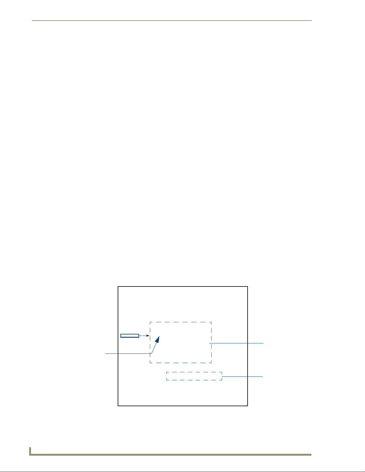
Configuring Communications
Using your NetLinx Master to control the G4 panel
Refer to your particular NetLinx Master’s instruction manual for detailed information on how to
download the latest firmware from www.amx.com. This firmware build enables SSL certificate
identification and encryption, HTTPS communication, ICSP data encryption, and disables the ability to
alter the Master security properties via a TELNET session.
In order to fully utilize the SSL encryption, your web browser should incorporate the an encryption
feature. This encryption level is displayed as a Cipher strength.
Once the Master’s IP Address has been set through NetLinx Studio version 2.x or higher:
1. Launch your web browser.
2. Enter the IP Address of the target Master (ex: http://198.198.99.99) into the web browser’s Address
field.
3. Press the Enter key on your keyboard to begin the communication process between the target
Master and your computer.
4. Click OK to enter the information and proceed to the Master’s Manage WebControl Connections
window.
5. This Manage WebControl Connections page (FIG. 33) is accessed by clicking on the Manage
connections link (within the Web Control section within the Navigation frame). Once activated, this
page displays links to G4 panels running the latest G4 Web Control feature (previously setup and
activated on the panel).
Initially, the Master Security option is disabled (from within the System Security page) and
no username and password is required for access or configuration.
Both HTTP and HTTPS Ports are enabled by default (via the Manage System > Server
page).
If the Master has been previously configured for secured communication, click OK to accept
the AMX SSL certificate (if SSL is enabled) and then enter a valid username and password
into the fields within the Login dialog.
40
G4 panels
FIG. 33 Manage WebControl Connections page (populated with compatible panels)
MVP-8400i Modero Viewpoint Wireless Touch Panels
Compatible
devices field
(showing G4
WebControl links)
Compression
Options
Page 51

Configuring Communications
6. Click on the G4 panel name link associated with the target panel. A secondary web browser window
appears on the screen (
FIG. 34 Web Control VNC installation and Password entry screens
FIG. 34).
7. Click Ye s from the Security Alert popup window to agree to the installation of the G4 WebControl
application on your computer. This application contains the necessary Active X and VNC client
applications necessary to properly view and control the panel pages from your computer.
The G4 Web Control application is sent by the panel to the computer that is used for
communication. Once the application is installed, this popup will no longer appear.
This popup will only appear if you are connecting to the target panel using a different
computer.
8. In some cases, you might get a Connection Details dialog (FIG. 35) requesting a VNC Server IP
Address. This is the IP Address not the IP of the Master but of the target touch panel. Depending on
which method of communication you are using, it can be found in either the:
Wired Ethernet - System Settings > IP Settings section within the IP Address field.
Wireless - Wireless Settings > IP Settings section within the IP Address field.
If you do not get this field continue to step 9.
IP Address of touch panel
- obtained from IP Settings section of
the Wireless Settings page (MVP)
FIG. 35 Connection Details dialog
9. If a WebControl password was setup on the G4 WebControl page, a G4 Authentication Session
password dialog box appears on the screen within the secondary browser window.
MVP-8400i Modero Viewpoint Wireless Touch Panels
41
Page 52

Configuring Communications
10. Enter the Web Control session password into the Session Password field (FIG. 35). This password
was previously entered into the Web Control Password field within the G4 Web Control page on the
panel.
11. Click OK to send the password to the panel and begin the session. A confirmation message appears
stating "Please wait, Initial screen loading..".
The secondary window then becomes populated with the same G4 page being displayed on the target G4
panel. A small circle appears within the on-screen G4 panel page and corresponds to the location of the
mouse cursor. A left-mouse click on the computer-displayed panel page equates to an actual touch on the
target G4 panel page.
42
MVP-8400i Modero Viewpoint Wireless Touch Panels
Page 53

Upgrading MVP Firmware
Except for the MVP-KS (Kickstand for MVP Panels), all MVP panels and their accessories have onboard firmware which is upgradeable through the use of the latest NetLinx Studio. The MVP acts as a
bridge between the NetLinx Studio program and the installed docking station. Studio can download
firmware to the target docking station by using the connected MVP to pass-along the Kit file to the
docking station. Refer to the NetLinx Studio version 2.x or higher Instruction Manual for more
information on how to download firmware to both a panel and a docking station.
The latest firmware 2.70.xx (or higher) kit file is panel-specific.
This new firmware also provides both backwards compatibility with the previous
802.11b cards and new security protocols for the new 802.11g wireless CF card.
1. Upload the latest Kit file (SW5965_xx version 2.70.xx or higher) to your specific Modero touch
panel and then confirm the firmware file update was successful. Refer to your panel’s instruction
manual for detailed communication and Kit file upload procedures.
If you don’t first update the firmware file on the panel, before proceeding with the card
upgrade process, you will be required to configure NetLinx Studio to communicate
with the target panel via a direct USB connection.
In this communication scenario, your PC acts as a Virtual NetLinx Master establishing
a secure USB connection to the target panel and then uploading the new Kit file.
Upgrading MVP Firmware
Before beginning the Upgrade process:
Setup and configure your NetLinx Master. Refer to the your particular NetLinx Master
Instruction Manual for detailed setup procedures.
Calibrate and prepare the communication pages on the Modero panel for use. Refer to the
Panel Calibration section on page 159.
Refer to the NetLinx Studio version 2.x or higher Help file for more information on uploading
files via Ethernet.
Configure your panel for either direct connect or wireless communication. Refer to the
Configuring Communications section on page 19 for more detailed information about
Ethernet or Wireless communication.
It is recommended that firmware Kit files only be transferred over a direct connection
and only when the panel is connected to a power supply.
If battery power or wireless connection fails during a firmware upgrade, the panel
flash file system may become corrupted.
The process of updating firmware involves the use of a communicating NetLinx Master. The required
steps for updating firmware to a Modero panel are virtually identical to those necessary for updating Kit
files to a NetLinx Master (except the target device is a panel instead of a Master). Refer to either your
Master’s literature or Studio 2.x Help file for those procedures.
A touch panel which is not using a valid username and password will not be able to
communicate with a secured Master. If you are updating the firmware on or through a
panel which is not using a username or password field, you must first remove the
Master Security feature to establish an unsecured connection.
MVP-8400i Modero Viewpoint Wireless Touch Panels
43
Page 54

Upgrading MVP Firmware
Upgrading the Modero Firmware via the USB port
Before beginning with this section, verify your panel is powered and the Type-A USB connector is
securely inserted into the PC’s USB port. The panel must be powered-on before connecting the mini-
USB connector to the panel.
Establishing a USB connection between the PC and the panel, prior to installing the
USB Driver will cause a failure in the USB driver installation.
Step 1: Configure the panel for a USB Connection Type
1. After the installation of the USB driver has been completed, confirm the proper installation of the
2. After the panel powers-up, press and hold the two lower buttons on both sides of the display for
3. Select Protected Setup > System Settings (located on the lower-left) to open the System Settings
4. Toggle the blue Typ e field (from the Master Connection section) until the choice cycles to USB.
large Type-A USB connector to the PC's USB port, and restart your machine.
3 seconds to continue with the setup process and proceed to the Setup page.
page.
ALL fields are then greyed-out and read-only, but still display any previous network
information.
5. Press the Back button on the touch panel to return to the Protected Setup page.
6. Press the on-screen Reboot button to both save any changes and restart the panel. Remember that
the panel’s connection type must be set to USB prior to rebooting the panel and prior to inserting
the USB connector.
7. ONLY AFTER the unit displays the first panel page, THEN insert the mini-USB connector into
the Program Port on the panel. It may take a minute for the panel to detect the new connection and
send a signal to the PC (indicated by a green System Connection icon).
If a few minutes have gone by and the System Connection icon still does not turn green,
complete the procedures in the following section to setup the Virtual Master and refresh the
System from the Online Tree. This action sends out a request to the panel to respond and
completes the communication (turning the System Connection icon green).
8. Navigate back to the System Settings page.
Step 2: Prepare Studio for communication via the USB port
1. Launch NetLinx Studio 2.x (default location is Start > Programs > AMX Control Disc > NetLinx
Studio 2 > NetLinx Studio 2).
2. Select Settings > Master Communication Settings, from the Main menu to open the Master
Communication Settings dialog (
FIG. 36).
3. Click the Communications Settings button to open the Communications Settings dialog.
4. Click on the NetLinx Master radio button (from the Platform Selection section) to indicate that you
are working as a NetLinx Master.
5. Click on the Virtual Master radio box (from the Transport Connection Option section) to indicate
you are wanting to configure the PC to communicate directly with a panel. Everything else such as
the Authentication is greyed-out because you are not going through the Master’s UI.
44
MVP-8400i Modero Viewpoint Wireless Touch Panels
Page 55

Upgrading MVP Firmware
IP Address of computer
(not needed as this is a direct
USB connection)
FIG. 36 Assigning Communication Settings for a Virtual Master
6. Click the Edit Settings button (on the Communications Settings dialog) to open the Virtual NetLinx
Master Settings dialog (
FIG. 36).
7. From within this dialog enter the System number (default is 1).
8. Click OK three times to close the open dialogs, save your settings, and return to the main NetLinx
Studio application.
9. Click the OnLine Tree tab in the Workspace window to view the devices on the Virtual System.
The default System value is one.
10. Right-click on the Empty Device Tree/System entry and select Refresh System to re-populate the
list.
The panel will not appear as a device below the virtual system number (in the Online Tree tab)
until both the system number used in step 7 for the VNM is entered into the Master Connection
section of the System Settings page and the panel is restarted.
Step 3: Confirm and Upgrade the firmware via the USB port
Use the CC-USB Type-A to Mini-B 5-wire programming cable (FG10-5965) to provide communication
between the mini-USB Program port on the touch panel and the PC. This method of communication is
used to transfer firmware Kit files and TPD4 touch panel files.
A mini-USB connection is only detected after it is installed onto an active panel.
Connection to a previously powered panel which then reboots, allows the PC to
detect the panel and assign an appropriate USB driver.
1. Verify this direct USB connection (Type-A on the panel to mini-USB on the panel) is configured
properly using the steps outlined in the previous two sections.
2. With the panel already configured for USB communication and the Virtual Master setup within
NetLinx Studio, its now time to verify the panel is ready to receive files.
3. After the Communication Verification dialog window verifies active communication between the
Virtual Master and the panel, click the OnLine Tree tab in the Workspace window (
view the devices on the Virtual System. The default System value is one.
4. Right-click on the System entry (FIG. 37) and select Refresh System to re-populate the list. Verify
the panel appears in the OnLine Tree tab of the Workspace window.
The default Modero panel value is 10001.
MVP-8400i Modero Viewpoint Wireless Touch Panels
FIG. 37) to
45
Page 56
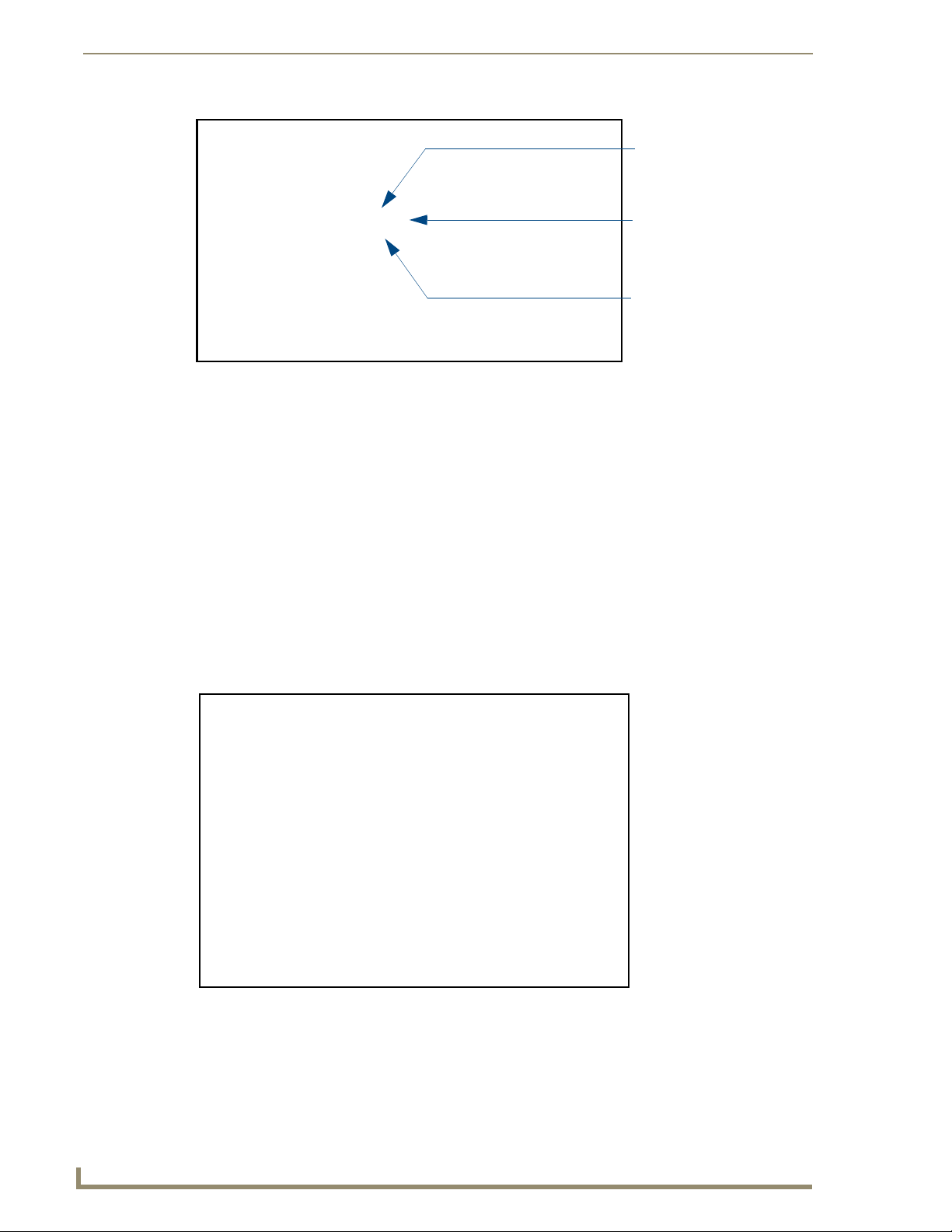
Upgrading MVP Firmware
FIG. 37 NetLinx Workspace window (showing panel connection via a Virtual NetLinx Master)
Showing the Virtual Master
firmware version and
device number
Shows NetLinx Studio
version number
Showing the current MVP
panel firmware version and
device number
The panel-specific firmware is shown on the right of the listed panel.
Download the latest firmware file from www.amx.com and then save the Kit file to
your computer. Note that each kit file is intended for download to its corresponding
panel.
5. If the panel firmware version is not the latest available; locate the latest firmware file from the
www.amx.com > Tech Center > Downloadable Files > Firmware Files > Modero Panels section
of the website.
6. Click on the desired Kit file link and after you’ve accepted the Licensing Agreement, verify you
have downloaded the Modero Kit file to a known location.
7. Select Tools > Firmware Transfers > Send to NetLinx Device from the Main menu to open the
Send to NetLinx Device dialog (B in
FIG. 38). Verify the panel’s System and Device number values
match those values listed within the System folder in the OnLine Tree tab of the Workspace
window (A in
FIG. 38).
A
B
46
FIG. 38 Using USB for a Virtual Master transfer
8. Select the panel’s Kit file from the Files section.
9. Enter the Device value associated with the panel and the System number associated with the Master
(listed in the OnLine Tree tab of the Workspace window). The Port field is greyed-out.
MVP-8400i Modero Viewpoint Wireless Touch Panels
Page 57

Upgrading MVP Firmware
10. Click the Reboot Device checkbox. This causes the touch panel to reboot after the firmware update
process is complete. The reboot of the panel can take up 30 seconds after the firmware process has
finished.
11. Click Send to begin the transfer. The file transfer progress is indicated on the bottom-right of the
dialog (B in
FIG. 38).
12. As the panel is rebooting, temporarily unplug the USB connector on the panel until the panel has
completely restarted.
13. Once the first panel page has been displayed, reconnect the USB connector to the panel.
14. Right-click the associated System number and select Refresh System. This causes a refresh of all
project systems, establishes a new connection to the Master, and populates the System list with
devices on your particular system.
15. Confirm the panel has been properly updated to the correct firmware version.
Upgrading the Docking Station Firmware via USB
The following accessory devices are firmware upgradeable:
MVP-TDS Table Top Docking Station (FG5965-10)
MVP-WDS Wall/Flush Mount Docking Station - Black (FG5965-11)
MVP-WDS Wall/Flush Mount Docking Station - Silver (FG5965-21)
This device is not given a unique device number which would ordinarily appear within the Online Tree
tab of NetLinx Studio. It appears as a battery base below the target panel which it is a part of as seen
below in
FIG. 39.
Target Panel Device #
TDS/WDS
(station version)
NetLinx Studio Online Tree tab
Accessory’s corresponding firmware page
FIG. 39 Location of Firmware version information within NetLinx Studio
The only way to upgrade the firmware of these accessory items is to send the accessory’s firmware
through a target panel. Its this panel’s device number which is entered within the Send to NetLinx Device
transfer dialog in Studio.
Step 1: Prepare the Docking Station for firmware transfer via USB
Before beginning with this section:
Verify the MVP is securely attached to the docking station and communicating properly.
Verify that the panel is communicating from the mini-USB port to the Virtual NetLinx Master
(VNM).
MVP-8400i Modero Viewpoint Wireless Touch Panels
47
Page 58

Upgrading MVP Firmware
1. Complete the instructions for configuring the NetLinx Master for IP communication found in the
2. After the panel powers-up, press and hold the two lower buttons on both sides of the display for
3. Press the Batteries button to open the Batteries page (FIG. 40).
FIG. 40 Batteries page
Upgrading the Modero Firmware via the USB port section on page 44.
3 seconds to continue with the setup process and proceed to the Setup page.
Displays the current
docking station firmware version
The docking station firmware is shown on the right of the Batteries page.
Verify you have downloaded the latest firmware file from www.amx.com and then
save the Kit file to your computer.
Step 2: Upgrade the Docking Station firmware via USB
1. Complete the procedures outlined in the Step 1: Configure the panel for a USB Connection
Type section on page 44.
2. Prepare NetLinx Studio for communication to the panel via a Virtual Master by following the
procedures outlined in the
Step 2: Prepare Studio for communication via the USB port section on
page 44.
3. After the Communication Verification dialog window verifies active communication between the
Virtual Master and the panel, click the OnLine Tree tab in the Workspace window to view the
devices on the Virtual System. The default System value is one.
4. Right-click on the System entry and select Refresh System to re-populate the list. Verify the panel
appears in the OnLine Tree tab of the Workspace window.
The default Modero panel value is 10001.
5. Locate the latest firmware file from the www.amx.com > Tech Center > Downloadable Files >
Firmware Files > Modero Panels firmware (MVP Docking Stations: MVP-TDS/WDS) section
of the website.
6. Click on the desired Kit file link and after you’ve accepted the Licensing Agreement, verify you
have downloaded the Docking Station Kit file to a known location.
7. Select Tools > Firmware Transfers > Send to NetLinx Device from the Main menu to open the
Send to NetLinx Device dialog (
FIG. 41). Verify the panel’s System and Device number values
match those values listed within the System folder in the OnLine Tree tab of the Workspace
window.
8. Select the docking station’s Kit file (ending in VXX.kit) from the Files section (FIG. 41).
9. Enter the Device number associated with the panel and the System number associated with the
Master (listed in the OnLine Tree tab of the Workspace window). The Port field is greyed-out.
48
MVP-8400i Modero Viewpoint Wireless Touch Panels
Page 59
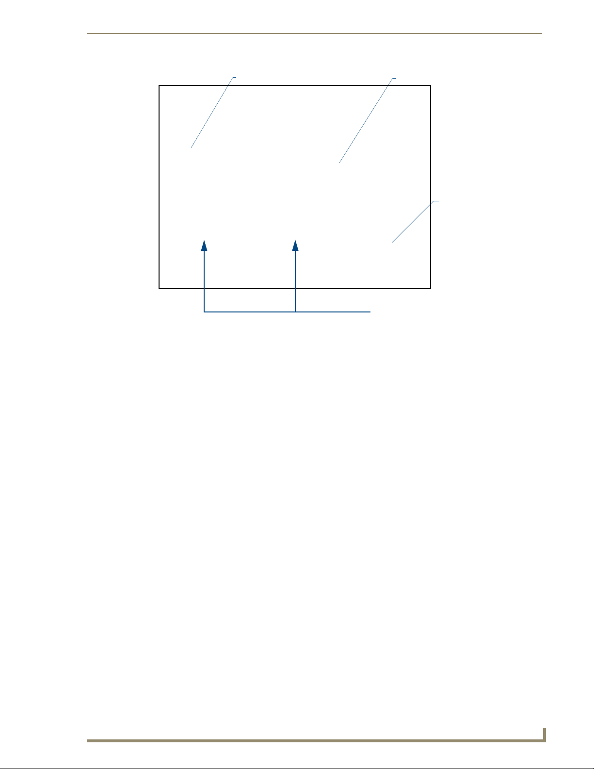
Upgrading MVP Firmware
Selected Docking Station Firmware file
FIG. 41 Send to NetLinx Device dialog (showing docking station firmware update via USB)
Description field for selected Kit file
Firmware download
status
Device and System values
must match the System and Device values
listed in the Project Navigator window
Firmware upgrades can not be done directly to the docking station but must be routed
through the MVP panel.
10. Click the Reboot Device checkbox. This causes the touch panel to reboot after the firmware update
process is complete. The reboot of the panel can take up 30 seconds after the firmware process has
finished.
11. Click Send to begin the transfer. The file transfer progress is indicated on the bottom-right of the
dialog.
12. As the panel is rebooting, temporarily unplug the USB connector on the panel until the panel has
completely restarted.
13. Once the first panel page has been displayed, reconnect the USB connector to the panel.
14. Right-click the associated System number and select Refresh System. This causes a refresh of all
project systems, establishes a new connection to the Master, and populates the System list with
devices on your particular system.
15. After the panel powers-up, press and hold the two lower buttons on both sides of the display for
3 seconds to continue with the setup process and proceed to the Setup page.
16. Press the Batteries button (located on the lower-left) to open the Batteries page and confirm the new
firmware does not read 0.00.
If the Base Version field displays 0.00, this means there was an error in the firmware
upload process. Re-install the base firmware and re-confirm that the new base
version no longer reads 0.00.
MVP-8400i Modero Viewpoint Wireless Touch Panels
49
Page 60

Upgrading MVP Firmware
Although firmware upgrades can be done over wireless Ethernet; it is recommended
that firmware KIT files be transferred over a direct USB connection and only when the
panel is connected to a power supply. If battery power or wireless connection fails
during a firmware upgrade, the panel flash file system may become corrupted.
50
MVP-8400i Modero Viewpoint Wireless Touch Panels
Page 61

Setup Pages
AMX Modero panels feature on-board Setup pages. Use the options in the Setup pages to access panel
information and make various configuration changes.
To access the Setup pages, press the two lower external pushbuttons on either side of the panel
simultaneously and hold for 3 seconds (
Setup Pages
FIG. 42).
Setup Page Access buttons:
Press and hold simultaneously for
3 seconds to access the Setup pages
Press and hold for 10 seconds
to access the Calibration page.
FIG. 42 Setup Page Access buttons
Navigation Buttons
The following Navigation buttons (FIG. 43) appear on the left side of the Setup page:
Closes the Setup page
Press to access the Protected Setup page for panel calibration and to access
security release passwords and connection settings.
Press to access the Information menu and select either Project Information or
Panel Information.
Press to access the Time Adjustment page where you can alter the time and
date settings on the Master.
Press to access the Volu me page where you can adjust audio parameters on the
panel.
Press to access the access the Batteries page to monitor MVP-BP Power Pack
status in the panel as well as the docking station.
FIG. 43 Setup Page Navigation Buttons
MVP-8400i Modero Viewpoint Wireless Touch Panels
51
Page 62
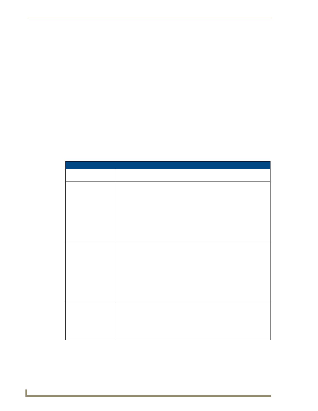
Setup Pages
Setup Pages
The Setup page (FIG. 44) allows quick access to several basic panel properties:
FIG. 44 MVP-8400 Setup page
Features on this page include:
Setup Page
Navigation Buttons: The buttons along on the left side of the page provide access to secondary Setup
pages (see following sections).
Connection Status icon: The icon in the upper-right corner of each Setup page shows online/offline state of
the panel to the master.
• Bright red - disconnected
• Bright green - connected. Blinks when a blink message is received to dark green
every 5 seconds for half a second then go back to bright green.
• Bright yellow - panel missed a blink message from the master. It will remain
yellow for 3 missed blink messages and then turn red. It will return to green
when a blink message is received.
Note: a Lock appears on the icon if the panel is connected to a secured NetLinx
Master.
Connection Status: Displays whether the panel is communicating externally as well as the encryption
status of the Master, the connection type (Ethernet or USB), and what System the
panel is connected to.
• Until a connection is established, the message displayed is: “Attempting via...”.
• When a connection is established, the message displayed is either: “Connected
via Ethernet “or “Connected via USB “.
• The word “Encrypted” appears when an encrypted connection is established with
a NetLinx Master.
Note: The panel must be rebooted before incorporating any panel communication
changes and to detect Ethernet connections.
Display Timeout: Indicates the length of time that the panel can remain idle before activating Sleep
mode (causing the LCD to power down).
• Press the UP/DN buttons to increase/decrease the Display Timeout setting.
Range = 0 - 240 (minutes).
• Set the timeout value to zero to disable Sleep mode.
Note: Small timeout values maximize the life of the battery charge.
52
MVP-8400i Modero Viewpoint Wireless Touch Panels
Page 63

Setup Pages
Setup Page (Cont.)
Inactivity Page Flip
Timeout:
Panel Brightness: Sets the display brightness level of the panel.
Indicates the length of time that the panel can remain idle before automatically flipping to a pre-selected page.
• Press the UP/DN buttons to increase/decrease the Inactivity Page Flip Timeout
setting. Range = 0 - 240 (minutes).
• Set the timeout value to zero to disable Inactivity Page Flip mode.
Note: The touch panel page used for the Inactivity page flip is shown within a small
Inactivity Page field.
• Press the UP/DN buttons to adjust the brightness level. Range = 0 - 100.
Note: The on-screen bargraph can be dragged to adjust the brightness level which
is then reflected as a numeric value in the Panel Brightness field.
Information
The Information button provides a menu to select either the Project Information Page section on
page 54 or the Panel Information Page section on page 56. Select either option to access that page.
FIG. 45 Information menu
MVP-8400i Modero Viewpoint Wireless Touch Panels
53
Page 64
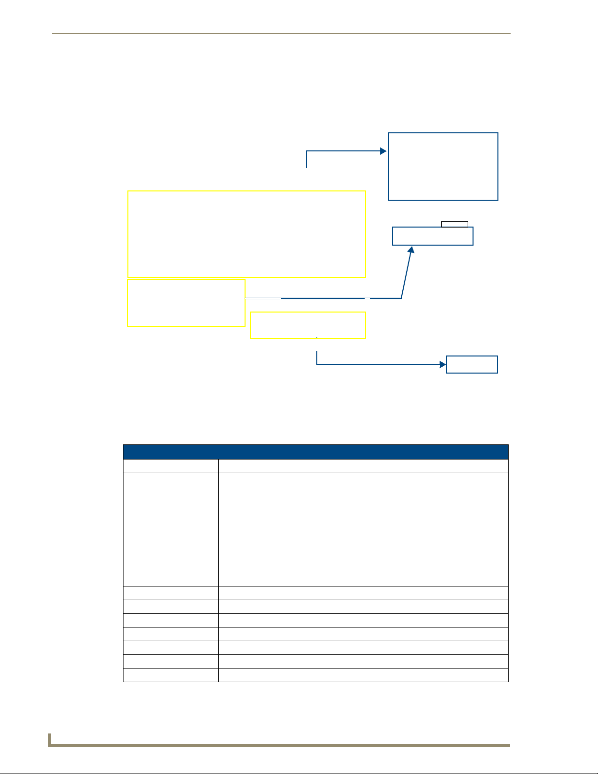
Setup Pages
Project Information Page
The Project Information page displays the project properties of the TPDesign4 project file currently
loaded on the panel (
FIG. 46).
FIG. 46 Project Information page and corresponding TPD4 project properties tabs
Features on this page include:
Project Information Page
Back: Saves all changes and returns to the previous page.
Connection Status icon: The icon in the upper-right corner of each Setup page shows online/offline state of
the panel to the master.
• Bright red - disconnected
• Bright green - connected. Blinks when a blink message is received to dark green
every 5 seconds for half a second then go back to bright green.
• Bright yellow - panel missed a blink message from the master. It will remain
yellow for 3 missed blink messages and then turn red. It will return to green
when a blink message is received.
Note: a Lock appears on the icon if the panel is connected to a secured NetLinx
Master.
File Name: Displays the name of the TPDesign4 project file downloaded to the panel.
Designer ID: Displays the designer information.
File Revision: Displays the revision number of the file.
Dealer ID: Displays the dealer ID number (unique to every dealer and entered in TPD4).
Job Name: Displays the job name.
Sales Order: Displays the sales order information.
Purchase Order: Displays the purchase order information.
54
MVP-8400i Modero Viewpoint Wireless Touch Panels
Page 65

Setup Pages
Project Information Page (Cont.)
AMX IR 38K Port: Displays the AMX 38 kHz IR channel port used by the IR Emitter on the panel.
• This information is specified in TPD4 (Project Properties > IR Emitters &
Receivers tab).
• For example if you set the AMX IR 38K Port to 7 and then put a button on the
panel with a channel code of 5 and a port of 7, it will trigger the IR code in slot 5
of the AMX IR 38K Port.
AMX IR 455K Port: Displays the AMX 455 kHz IR channel port used by the IR Emitter on the panel.
IR User Def 1 Port: Displays the User Defined IR channel port used by the IR Emitter on the panel.
• Note: User Defined ports can be downloaded by the user and are customizable,
whereas the AMX ones are fixed.
IR User Def 2 Port: Displays the User Defined IR channel port used by the IR Emitter on the panel.
Build Number: Displays the build number information of the TPD4 software used to create the
Creation Date: Displays the project creation date.
Revision Date: Displays the last revision date for the project.
Last Save Date: Displays the last date the project was saved.
Blink Rate: Displays the feedback blink rate, in .10 second increments.
Job Comments: Displays any comments associated to the job (from the TPD4 project file).
Cradle Sensor Port: Displays the port assignment being used to report Cradle Sensor information.
Cradle Sensor Channel: Displays the channel assignment being used to report Cradle Sensor information.
project file.
The channel is turned on when the panel is docked (in either the TDS or WDS
docking stations.
IR receivers and transmitters on G4 panels share the device address number of the
panel.
MVP-8400i Modero Viewpoint Wireless Touch Panels
55
Page 66

Setup Pages
Panel Information Page
The Panel Information page provides detailed panel information (FIG. 47).
FIG. 47 Panel Information page (takes its’ information from the touch panel)
Features on this page include:
Panel Information Page
Back: Saves all changes and returns to the previous page.
Connection Status icon: The icon in the upper-right corner of each Setup page shows online/offline state
Panel Type: Displays the model of the panel being used.
Firmware Version: Displays the version number of the G4 firmware loaded on the panel.
Setup Port: Displays the setup port information (value) being used by the panel.
High Port: Displays the high port (port count) value for the panel.
High Address: Displays the high address (address count) value for the panel.
High Channel: Displays the high channel (channel count) value for the panel.
High Level: Displays the high level (level count) value being used by the panel.
Serial Number: Displays the specific serial number value assigned to the panel.
Setup Pages Version: Displays the type and version of the Setup pages being used by the panel.
Screen Width: Displays the screen width (in pixels).
Screen Height: Displays the screen height (in pixels).
of the panel to the master.
• Bright red - disconnected
• Bright green - connected. Blinks when a blink message is received to dark
green every 5 seconds for half a second then go back to bright green.
• Bright yellow - panel missed a blink message from the master. It will remain
yellow for 3 missed blink messages and then turn red. It will return to green
when a blink message is received.
Note: a Lock appears on the icon if the panel is connected to a secured NetLinx
Master.
• MVP-8400 = 800
• MVP-8400 = 600 pixels.
56
MVP-8400i Modero Viewpoint Wireless Touch Panels
Page 67

Setup Pages
Panel Information Page (Cont.)
Screen Refresh Rate: Displays the video refresh rate applied to the incoming video signal from the
Screen Rotation: Displays the degree of rotation applied to the on-screen image.
Power Up Pages: Displays the page assigned to display after the panel is powered-up.
Start Up String: Displays the start-up string.
Wake Up String: Displays the wake up string used after an activation from a timeout.
Sleep String: Displays the sleep string used during a panel’s sleep mode.
File System: Displays the amount of Compact Flash memory available on the panel.
RAM: Displays the available RAM (or Extended Memory module) on the panel.
Panel Start Time: Displays the last time the panel booted.
panel.
Time & Date Setup Page
The options on the Time & Date Setup page (FIG. 48) allow you to set and adjust time and date
information on the NetLinx Master. If the time and/or date on the Master is modified, all connected
devices will be updated to reflect the new information.
FIG. 48 Time and Date Setup page
MVP touch panels do not have an on-board clock; the only way to modify a panel’s
time without altering the Master is via NetLinx Code.
MVP-8400i Modero Viewpoint Wireless Touch Panels
57
Page 68

Setup Pages
Features on this page include:
Time & Date Setup Page
Back: Saves all changes and returns to the previous page.
Connection Status icon: The icon in the upper-right corner of each Setup page shows online/offline state of
the panel to the master.
• Bright red - disconnected
• Bright green - connected. Blinks when a blink message is received to dark green
every 5 seconds for half a second then go back to bright green.
• Bright yellow - panel missed a blink message from the master. It will remain
yellow for 3 missed blink messages and then turn red. It will return to green
when a blink message is received.
Note: a Lock appears on the icon if the panel is connected to a secured NetLinx
Master.
Time Date Refresh/Set: This section provides two options:
• The Get Time/Date button retrieves Time and Date information from the Master.
• The Set Time/Date button sets the Master to retain and save any time/date
modifications made on the panel.
Time Display fields: • These fields display the time in three formats: STANDARD, STANDARD AM/PM,
and 24 HOUR.
Date Display fields: • These fields display the calendar date information in several different formats.
Set Date/Time: Use the UP/DN arrow buttons to adjust the Master’s calendar date and time. The
blue icon indicates which field is currently selected (see
• Year range = 2000 - 2037
• Month range = 1 - 12
• Day range = 1 - 31
• Hour = 24-hour military
• Minute range = 0 - 59
• Second range = 0 - 59
FIG. 48).
58
MVP-8400i Modero Viewpoint Wireless Touch Panels
Page 69

Setup Pages
Volume Page
The MVP-8400 provides a Vo lu m e page (FIG. 49) with options that allow you to adjust volume levels,
set intercom sound and microphone levels, and set panel sounds.
FIG. 49 Audio Adjustments/Volume pages
Features on these pages include:
Volume Page
Back: Saves all changes and returns to the previous page.
Connection Status icon: The icon in the upper-right corner of each Setup page shows online/offline state
of the panel to the master.
• Bright red - disconnected
• Bright green - connected. Blinks when a blink message is received to dark
green every 5 seconds for half a second then go back to bright green.
• Bright yellow - panel missed a blink message from the master. It will remain
yellow for 3 missed blink messages and then turn red. It will return to green
when a blink message is received.
Note: a Lock appears on the icon if the panel is connected to a secured NetLinx
Master.
Master Volume: This section allows you to alter the current master volume level:
• Use the UP/DN buttons to adjust the volume level (range = 0 - 100).
• The Master Volume bargraph indicates the current volume level.
• The Mute button toggles the Mute feature.
Default = 50
MVP-8400i Modero Viewpoint Wireless Touch Panels
59
Page 70

Setup Pages
Volume Page (Cont.)
Default Panel Sounds: • Activating the Button Hit button plays a default sound when you touch an
active button.
• Activating the Button Miss button plays a default sound when you touch a
non-active button or any area outside of the active button
• The Play Test Sound button plays a test WAV/MP3 file over the panel’s
internal speakers.
Internal Sound Level: Adjusts the volume level on the panel’s internal speaker:
• Use the UP/DN buttons to adjust the volume (range = 0 - 100)
• The Internal Sound Level bargraph indicates the current sound level
• The Mute button mutes the internal speaker volume
Default = 50
Intercom Mic Level: Adjusts the volume level on the panel’s microphone
• Use the UP/DN buttons to adjust the microphone level (range = 0 - 100)
• The Mic Out Level bargraph indicates the current Mic Out level
Default = 40
Intercom Sound Level: Sets the volume level for intercom calls
• Use the UP/DN buttons to adjust the Line-In volume level (range = 0 - 100)
• The Line-In Level bargraph indicates the current Line-In level
• The Mute button mutes the Line-In volume
Default = 40
Environmental acoustics, personal voice level and ambient noise are all deciding factors when setting
your mic, intercom and panel sound levels. Consider your environment when adjusting intercom and
sound levels and use caution so as not to damage the speaker.
WAV files - Supported sample rates
The following sample rates for WAV files are supported by MVP-8400 panels:
Supported WAV Sample Rates
• 48000 Hz • 16000 Hz
• 44100 Hz • 12000 Hz
• 32000 Hz • 11025 Hz
• 24000 Hz • 8000 Hz
• 22050 Hz
60
MVP-8400i Modero Viewpoint Wireless Touch Panels
Page 71

Setup Pages
Batteries Page
The options on this page allow you to set power warning preferences, monitor battery status information,
and adjust the display times for battery warnings. This page is populated with information from MVPBP batteries in the panel, as well as batteries in a connected MVP-TDS/WDS docking station (
FIG. 50).
FIG. 50 Batteries page
Features on this page include:
Batteries Page
Back: Saves all changes and returns to the previous page.
Connection Status icon: The icon in the upper-right corner of each Setup page shows online/offline state
Battery Power Brightness
Limit:
Panel Shutdown: This value determines the number of minutes that would need to pass before
of the panel to the master.
• Bright red - disconnected
• Bright green - connected. Blinks when a blink message is received to dark
green every 5 seconds for half a second then go back to bright green.
• Bright yellow - panel missed a blink message from the master. It will remain
yellow for 3 missed blink messages and then turn red. It will return to green
when a blink message is received.
Note: a Lock appears on the icon if the panel is connected to a secured NetLinx
Master.
The DISABLE/DISABLED button acts as a power save feature with two options:
• Disable - activates the brightness limit set on the panel (conserves battery
power). Activating this feature causes the panel to function at 80% of full
brightness and overrides the Panel Brightness value set on the Setup page.
• Disabled - deactivates this power save feature. The panel will use the Panel
Brightness level.
Note: This field applies to MVP-BP batteries installed in the panel.
the panel automatically shuts-down. Once shutdown, the unit would have to be
restarted. The UP/DN buttons alter the timeout value (in minutes). A value of 0
disables this feature.
Range = 0 - 240, default = 1200 min.
Note: This field applies to MVP-BP batteries installed in the panel.
MVP-8400i Modero Viewpoint Wireless Touch Panels
61
Page 72

Setup Pages
Batteries Page (Cont.)
Low Battery Warning: The UP/DN buttons adjust the time value (in minutes) available on the battery
(for use) before the panel displays a low battery warning.
Range - 10 - 45, default = 15 min.
Note: This field applies to MVP-BP batteries installed in the panel.
Very Low Battery Warning: The UP/DN buttons adjust the time value (in minutes) available on the battery
before the panel displays a very low battery warning (indicating near-term panel
shutdown).
• Range = 3 - 15, default = 5 min.
• This value cannot exceed the Low Battery Warning value.
Note: This field applies to MVP-BP batteries installed in the panel.
Battery Status: • The Combined Charge Status bargraph indicates the combined power
charge available from batteries installed in the panel.
• The Battery One Charge Status bargraph indicates the power charge
available on the Slot 1 battery (in the panel).
• The Battery Two Charge Status bargraph indicates the power charge
available on the Slot 2 battery (in the panel).
• The Battery Dock 1 Charge Status bargraph indicates the power charge
available on the docking station’s battery #1.
• The Battery Dock 2 Charge Status bargraph indicates the power charge
available on the docking station’s battery #2.
Note: If no batteries are being charged within the docking station’s battery compartments, or the MVP is not connected to a docking station; both Battery Dock
Charge Status fields are left blank.
• The Docking Station Version field indicates the firmware version currently
installed on the docking station.
• The Battery Level Port field indicates the port being used to report charge
status levels back to the NetLinx Master (set in TPDesign4).
• The Battery Level field indicates the level being used to report status levels
back to the NetLinx Master (set in TPDesign4).
62
MVP-8400i Modero Viewpoint Wireless Touch Panels
Page 73

Setup Pages
Protected Setup Pages
The Protected Setup page (FIG. 51) provides secured access to advanced panel configuration options,
including communication and security settings.
Enter the factory default password (1988) into the password keypad to access this page.
FIG. 51 Protected Setup page showing default values
Features on the Protected Setup page include:
Protected Setup Page
Back: Saves all changes and returns to the previous page.
Connection Status icon: The icon in the upper-right corner of each Setup page shows online/offline state
of the panel to the master.
• Bright red - disconnected
• Bright green - connected. Blinks when a blink message is received to dark
green every 5 seconds for half a second then go back to bright green.
• Bright yellow - panel missed a blink message from the master. It will remain
yellow for 3 missed blink messages and then turn red. It will return to green
when a blink message is received.
Note: a Lock appears on the icon if the panel is connected to a secured NetLinx
Master.
Navigation Buttons: The buttons along on the left side of the page provide access to secondary Pro-
Device Number: Opens a keypad used to view/set the device number of the panel.
tected Setup pages (see following sections).
MVP-8400i Modero Viewpoint Wireless Touch Panels
63
Page 74
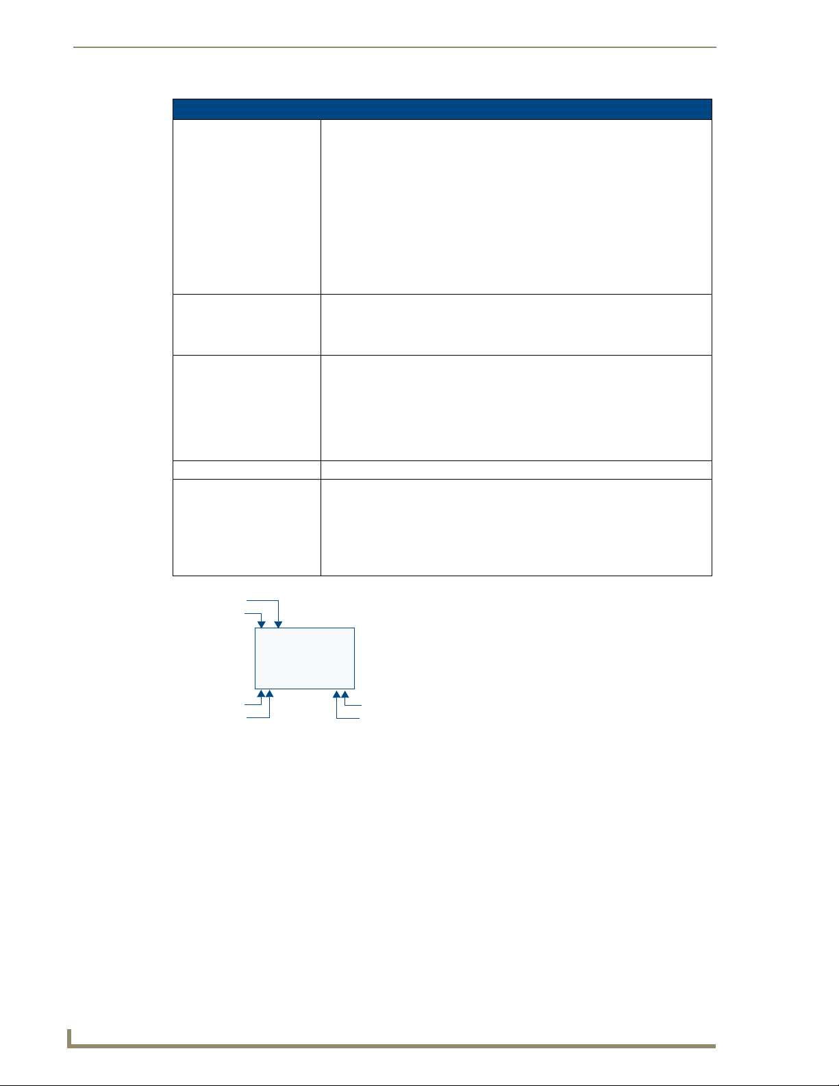
Setup Pages
Protected Setup Page (Cont.)
Options: • Function Show - toggles the display of the channel port, channel code, level
System Recovery: • Reset System Settings - deletes all of the current configuration parameters
System Recovery (Cont.): • Remove User Pages - allows you remove all TPD4 touch panel pages
Reboot Panel: Pressing this button causes the panel to reboot after saving any changes.
Docking Station: • Dock Status - illuminates when the MVP is docked and communicating with
port and level code on all touch panel buttons (see
• Page Tracking - toggles the page tracking function. When enabled, the panel
reports page data to the NetLinx Master.
• Tel net - enables/disables the panel’s telnet server (to allow direct telnet
communication to the panel).
• Front Button Setup Access - activates the two lower buttons on the front of
the panel for accessing the Setup and Calibration pages (see
page 51). The default setting is On.
- Press and hold these buttons for 3 seconds to access the Setup page.
- Press and hold these buttons for 6 seconds to access the Calibration page.
on the panel (including IP Addresses, Device Number assignments,
Passwords, and other presets). This option invokes a Confirmation dialog,
prompting you to confirm your selection before resetting the panel.
currently on the panel, including the pre-installed AMX Demo pages. This
option invokes a Confirmation dialog, prompting you to confirm your selection
before removing the panel pages.
Note that the YES button on the Confirmation dialog is disabled for 5 seconds
as additional protection against accidentally resetting the panel or removing
the panel pages.
the Docking Station.
• Undock Panel - forces the docking station to release the MVP without
requiring a User Access username or password.
• Disable Docking Station LED - disables the display of the LEDs on the
docking station.
FIG. 52).
FIG. 42 on
Channel Code
Channel Port
3,132
BUTTON
2,8 3,50
Level Port
Channel Code
FIG. 52 Function Show example
Address Port
Address Code
Protected Setup Navigation Buttons
The Protected Setup Navigation Buttons (FIG. 53) appear on the left of the panel screen when the
Protected Setup page is currently active.
64
MVP-8400i Modero Viewpoint Wireless Touch Panels
Page 75
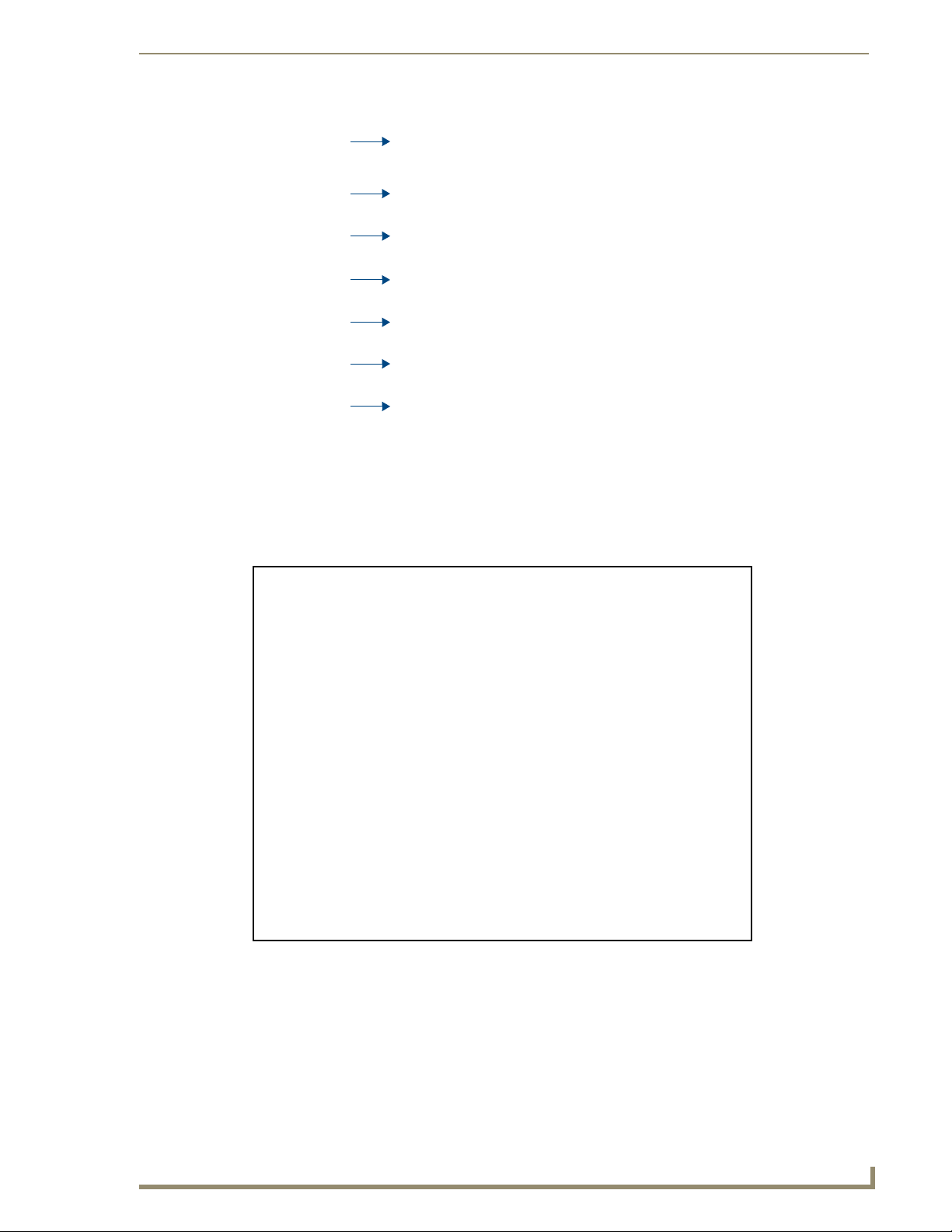
Setup Pages
Closes the Protected Setup page.
Press to access the System Settings page where you can configure
communication settings for the NetLinx Master and the panel.
Press to access the Wireless Settings page where you can configure wireless
connection settings.
Press to access the Calibration page where you can calibrate the panel. Press and
hold to access the Calibration Test page.
Press to access the G4 Web Control page where you can enable or disable remote
display and control of the panel via a web-enabled PC running a VNC client.
Press to access the Other Settings menu, and select Cache, Passwords, or
SIP.
Press to access the Too ls menu and select Panel Logs, Panel Statistics, or
Connection Utility.
FIG. 53 Protected Setup Navigation Buttons
G4 Web Control Page
An on-board VNC (Virtual Network Computing) server allows the panel to connect to any remote PC
running a VNC client. Once connected, the client can view and control the panel remotely. The options
on this page allow you to enable/disable G4 Web Control functionality(
FIG. 54).
FIG. 54 G4 Web Control page
MVP-8400i Modero Viewpoint Wireless Touch Panels
65
Page 76

Setup Pages
Features on this page include:
G4 Web Control Page
Back: Saves all changes and returns to the previous page.
Connection Status icon: The icon in the upper-right corner of each Setup page shows online/offline state
of the panel to the master.
• Bright red - disconnected
• Bright green - connected. Blinks when a blink message is received to dark
green every 5 seconds for half a second then go back to bright green.
• Bright yellow - panel missed a blink message from the master. It will remain
yellow for 3 missed blink messages and then turn red. It will return to green
when a blink message is received.
Note: a Lock appears on the icon if the panel is connected to a secured NetLinx
Master.
G4 Web Control Settings: Sets the IP communication values for the touch panel:
Enable/Enabled The Enable/Enabled button allows you to toggle between the two G4 activation
settings:
• Enable - deactivates G4 Web Control on the panel.
• Enabled - activates G4 Web Control on the panel.
Network Interface Select Displays “Wireless” when the panel is communicating via a Wireless Access
Point (WAP).
Web Control Name Use this field to enter a unique alpha-numeric string to be used as the panel’s
display name within the Manage WebControl Connections window of the
NetLinx Security browser window.
Web Control Password Use this field to enter the G4 Authentication session password required for
VNC access to the panel.
Web Control Port Enter the number of the port used by the VNC Web Server. Default = 5900.
Maximum Number of
Connections
Current Connection Count Displays the number of users currently connected to this panel via VNC.
G4 Web Control Timeout: Sets the length of time (in minutes) that the panel can remain idle (no cursor
Displays the maximum number of users that can be simultaneously connected
to this panel via VNC. Default = 1.
movements) before the G4 Web Control session is terminated.
• Minimum value = 0 minutes (panel never times out)
• Maximum value = 240 minutes (panel times out after 240 minutes)
66
Refer to the Using G4 Web Control to Interact with a G4 Panel section on page 38 for
instructions on using the G4 Web Control page with the web-based NetLinx Security
application.
MVP-8400i Modero Viewpoint Wireless Touch Panels
Page 77

Calibration Page
This page (FIG. 55) allows you to calibrate the touch panel for accurate button selection.
Setup Pages
FIG. 55 Calibration page
Press and hold the two lower button on both sides of the display for 6 seconds to access the
Calibration page (see
Press the crosshairs to calibrate the panel and return to the previous page.
FIG. 76 on page 159).
Always calibrate the panel before its initial use, and after downloading new firmware.
In cases where the touch panel calibration is off to a degree that makes it difficult or
impossible to navigate to this page, you can access it via G4 WebControl, so you can
re-calibrate the panel.
MVP-8400i Modero Viewpoint Wireless Touch Panels
67
Page 78

Setup Pages
Wireless Settings Page
Use the options on the Wireless Settings page (FIG. 56) to configure communication settings for the
wireless CF card (802.11g), and read the device number assigned to the panel.
FIG. 56 Wireless Settings page (reads from and assigns values to the WAP)
Features on this page include:
Wireless Settings Page
Back: Saves all changes and returns to the previous page.
Connection Status icon: The icon in the upper-right corner of each Setup page shows online/offline state
IP Settings: Sets the IP communication values for the panel:
DHCP/STATIC Sets the panel to either DHCP or Static communication modes.
IP Address Enter the secondary IP address for this panel.
Subnet Mask Enter the subnetwork address for this panel.
Gateway Enter the gateway address for this panel.
Host Name Enter the host name for this panel.
Primary DNS Enter the address of the primary DNS server used by this panel for host name
Secondary DNS Enter the secondary DNS address for this panel.
of the panel to the master.
• Bright red - disconnected
• Bright green - connected. Blinks when a blink message is received to dark
green every 5 seconds for half a second then go back to bright green.
• Bright yellow - panel missed a blink message from the master. It will remain
yellow for 3 missed blink messages and then turn red. It will return to green
when a blink message is received.
Note: a Lock appears on the icon if the panel is connected to a secured NetLinx
Master.
• DHCP - a temporary IP Addresses is assigned to the panel by a DHCP
server.
• Static IP is a permanent IP Address assigned to the panel. If Static IP is
selected, the other IP Settings fields are enabled (below).
lookups.
68
MVP-8400i Modero Viewpoint Wireless Touch Panels
Page 79
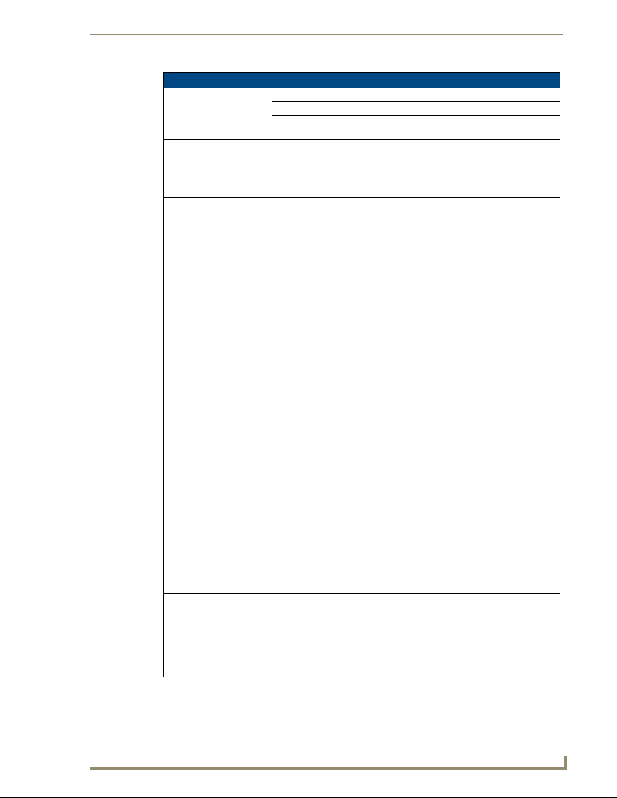
Setup Pages
Wireless Settings Page (Cont.)
IP Settings (Cont.):
Domain Enter a unique name to the panel for DNS look-up.
MAC Address This unique address identifies the wireless Ethernet card in the panel (read-
only).
Active Roaming on
Channels 1,6,11
Access Point MAC
Address:
Wireless Security: Sets the wireless security method to be used by the panel to connect to the net-
Open (Clear Text) This button opens the Open (Clear Text) Settings page (FIG. 57 on page 72).
Static W EP This button opens the Static WEP Settings page (FIG. 58 on page 73).
WPA-PSK This button opens the WPA-PSK Settings page (FIG. 59 on page 75).
When enabled, the device is actively roaming on the channels 1, 6, and 11. By
default, Active Roaming is disabled.
Of all the frequency channels that are assigned for wireless, only three are
nonoverlapping frequencies that do not interfere with each other.
Nonoverlapping channels avoid the interference that can affect the signal.
This unique address identifies the Wireless Access Point (WAP) used by this
panel for wireless communication (read-only).
• Site Survey button: Launches the Site Survey page. The options on this page
allow you to detect (“sniff-out”) all WAPs transmitting within range of the
panel’s NXA-WC80211GCF Wi-Fi card.
Data displayed on the Site Survey page is categorized by:
- Network Name (SSID) - WAP names
- Channel (RF) - channels currently being used by the WAP
- Security Type - security protocol enabled on the WAP, if detectable
- Signal Strength - None, Poor, Fair, Good, Very Good, and Excellent
- MAC Address - Unique identification of the transmitting Access Point
• Refer to the Using the Site Survey tool section on page 22 for more detailed
information on the SIte Survey page.
• When communicating with a NXA- WAP200G, enter the MAC Address
(BSSID) of the target WAP as the Access Point MAC Address. Refer to the
WAP200G Instruction Manual for more information.
work. Selecting any of the connection method buttons invokes the relevant configuration page, with options that allow you to define parameters specific to the
selected method of connection.
• Refer to the following Wireless Security Page section on page 71 for further
details on these security options.
“Open” security does not utilize any encryption methodology, but requires an
SSID (alpha-numeric) entry. This entry must match the Network Name (SSID)
entry of the target WAP so the panel knows what device it is using to communi
cate with the network.
• Refer to the following Wireless Security Page section on page 71 for further
details on these security options.
“Static WEP” security requires that both a target WAP be identified and an
encryption method be implemented prior to establishing communication.
• Refer to the Wireless Security Page section on page 71 for further details on
these security options.
“WPA-PSK” security is designed for environments where is it desirable to use
WPA or WPA2, but an 802.1x authentication server is not available.
PSK connections are more secure than WEP and are simpler to configure since
they implement dynamic keys but share a key between the WAP and the panel
(client).
• Refer to the Wireless Security Page section on page 71 for details.
-
MVP-8400i Modero Viewpoint Wireless Touch Panels
69
Page 80
Setup Pages
Wireless Settings Page (Cont.)
Wireless Security (Cont.):
EAP-PEAP This button opens the EAP-PEAP Settings page (FIG. 63 on page 80).
“EAP-PEAP” security is designed for wireless environments where it is necessary to securely transmit data over a wireless network.
• Refer to the Wireless Security Page section on page 71 for details.
• For information on uploading a certificate file, refer to the AMX Certificate
Upload Utility section on page 175.
EAP-TTLS This button opens the EAP-TTLS Settings page (FIG. 64 on page 82).
“EAP-TTLS” security is designed for wireless environments where it is
necessary to first have a Radius server directly validate the identity of the client
(panel) before allowing it access to the network.
• Refer to the Wireless Security Page section on page 71 for details.
• For information on uploading a certificate file, refer to the AMX Certificate
Upload Utility section on page 175.
EAP-TLS This button opens the EAP-TLS Settings page (FIG. 65 on page 84).
“EAP-TLS” security is designed for wireless environments where it is necessary
to securely transmit data over a wireless network by adding an additional level
of security protocol via the use of a private key.
• Refer to the Wireless Security Page section on page 71 for details.
• For information on uploading a certificate file, refer to the AMX Certificate
Upload Utility section on page 175.
EAP-LEAP This button opens the EAP-LEAP Settings page (FIG. 60 on page 76).
“EAP-LEAP” security is designed for wireless environments where it is not
required to have both a client or server certificate validation scheme in place,
yet necessary to securely transmit data over a wireless network.
• Refer to the Wireless Security Page section on page 71 for details.
EAP-FAST This button opens the EAP-FAST Settings page (FIG. 62 on page 78).
“EAP-FAST” security is designed for wireless environments where security and
ease of setup are equally desirable.
• Refer to the Wireless Security Page section on page 71 for details.
Site Survey: The Site Survey tool allows you to detect and view detailed information on all
WAPs within the panel’s communication area. Using this tool, you can select a
WAP to connect to.
• Refer to the Using the Site Survey tool section on page 22 for information on
using this tool.
RF Link Info: These options set communication values for the wireless interface card:
SSID Displays the currently used SSID of the target WAP.
Channel The RF channel being used for connection to the WAP (read -only).
Link Quality Displays the quality of the link from the wireless NIC to the Wireless Access
Point (direct sequence spread spectrum) in real time (None, Poor, Fair, Good,
Very Good, and Excellent).
• Even when link quality is at its lowest you still have a connection, and the
ability to transmit and receive data, even if at lower speeds.
Note: “Link Quality” and “Signal Strength” are applicable to RF connections
only. It is possible to have an RF signal to a WAP, but be unable to communi
cate with it because of either incorrect IP or encryption settings.
-
70
MVP-8400i Modero Viewpoint Wireless Touch Panels
Page 81

Setup Pages
Wireless Settings Page (Cont.)
RF Link Info: (Cont.)
Signal Strength This indicator displays a description of the signal strength from the Wireless
Access Point connection in real time (None, Poor, Fair, Good, Very Good, and
Excellent).
SNR (Signal Noise Ratio) is a measure of the relative strength of a wireless RF
connection. Given this value and the link quality above, you can determine the
noise level component of the SNR. For example, if signal strength is high but
the link quality is low, then the cause of the link degradation is noise. However,
if signal strength is low and link quality is low the cause would simply be signal
strength.
Data Rate The data rate (in Mbps) at which the panel is currently communicating with the
target WAP.
Note: Data rates for 802.11b communication are: 1, 2, 5.5, and 11 Mbps.
Wireless Security Page
The options on the Wireless Security page allow you to select from the wireless security methods
supported by the NXA-WC80211GCF Wi-Fi card. These security methods incorporate WPA, WPA2, and
EAP technology (some of which require the upload of unique certificate files to a target panel).
Refer to the Appendix B - Wireless Technology section on page 169 for more further information.
Some encryption and security features may/may not be supported depending on the type of wireless card
being used:
Wireless Security Support
802.11g Wi-Fi CF card: • Open (Clear Text)
• Static WEP (64-bit and 128-bit key lengths)
• WPA-PSK
• EAP security (with and without certificates)
• WAP SIte Survey
Refer to the Configuring a Wireless Network Access section on page 21 for more information on
configuring the panel for wireless network access using the various security options.
802.11g wireless card
Wireless Security pages (each Wi Fi card supports different security features)
MVP-8400i Modero Viewpoint Wireless Touch Panels
71
Page 82

Setup Pages
Open (Clear Text) Settings
Press the Open (Clear Text) button to open the Open (Clear Text) Settings page (FIG. 57).
FIG. 57 Wireless Settings page - Open (Clear Text) Settings
Open security does not utilize any encryption methodology, but requires an SSID (alpha-numeric) entry.
This entry must match the Network Name (SSID) entry of the target WAP so the panel knows what
device it is using to communicate with the network.
Open (Clear Text) Settings
SSID (Service Set Identifier): Opens an on-screen keyboard to enter the SSID name used on the target
WAP.
The SSID is a unique name used by the WAP, and is assigned to all panels
on that network. An SSID is required by the WAP before the panel is permit
ted to join the network.
• The SSID is case sensitive and must not exceed 32 characters.
• Make sure this setting is the same for all points in your wireless network.
• NXA-WAP200Gs use AMX as their default SSID.
• If this field is left blank, the panel will attempt to connect to the first available
WAP.
Save/Cancel: • Save - store the new security information, apply changes, and return to the
previous page.
• Cancel - discard changes and return to the previous page.
Refer to the Configuring a Wireless Network Access section on page 21 for further details on
-
these security options.
Refer to the Using the Site Survey tool section on page 22.
72
MVP-8400i Modero Viewpoint Wireless Touch Panels
Page 83

Static WEP Settings
Press the Static WEP button to open the Static WEP Settings page (FIG. 58).
FIG. 58 Wireless Settings page - Static WEP Settings
Setup Pages
Static WEP security requires that both a target WAP be identified and an encryption method be
implemented prior to establishing communication. In addition to providing both Open and Shared
Authentication capabilities, this page also supports Hexadecimal and ASCII keys.
Static WEP Settings
SSID (Service Set Identifier): Opens an on-screen keyboard to enter the SSID name used on the target
WEP 64 / WEP 128: Cycles through the available encryption options: 64 or 128 Bit Key Size.
WAP.
The SSID is a unique name used by the WAP, and is assigned to all panels
on that network. An SSID is required by the WAP before the panel is permit
ted to join the network.
• The SSID is case sensitive and must not exceed 32 characters.
• Make sure this setting is the same for all points in your wireless network.
• NXA-WAP200Gs use AMX as their default SSID.
• If this field is left blank, the panel will attempt to connect to the first available
WAP.
“WEP” (Wired Equivalent Privacy) is an 802.11 security protocol designed to
provide wireless security equivalent to wired networks.
• WEP64 enables WEP encryption using a 64 Bit Key Size. All packets are
transmitted with their contents encrypted using the Default WEP Key.
• WEP128 enables WEP encryption using a 128 Bit Key Size. All packets are
transmitted with their contents encrypted using the Default WEP Key.
• If the key is not the correct size, the system will resize it to match the
number of bits required for the WEP encryption mode selected.
-
MVP-8400i Modero Viewpoint Wireless Touch Panels
73
Page 84

Setup Pages
Static WEP Settings (Cont.)
Generate (Passphrase): This button displays an on-screen keyboard which allows you to enter a pass-
phrase. The panel then automatically generates four WEP keys (compatible
only with Modero panels). Enter these WEP keys into the target WAP.
When working with multiple panels, WEP Keys must be entered into the WAP
for each panel.
• All Modero panels use the same code key generator. Therefore, this
Passphrase generates identical keys on any Modero panel.
• The Passphrase generator is case sensitive.
Note: This Key generator is unique to Modero panels and does not generate
the same keys as non-AMX wireless devices. For example, a Current Key
string generated anywhere else will not match those created on Modero pan
els.
Default Key: Cycles through the four available WEP key identifiers to select a WEP key to
use. As the Default Key value is altered (through selection) the corresponding
“Current Key” is displayed. Each Current Key corresponds to a WEP key.
This feature is useful for accessing different networks without having to reenter that networks’ WEP key. It is also sometimes used to set up a rotating
key schedule to provide an extra layer of security.
WEP Keys: This feature provides another level of security by selecting up to four WEP
Keys.
Push any of the four buttons to open an on-screen keyboard. Both ASCII and
HEX keys are supported. Up to four keys can be configured for both.
• An ASCII key utilizes either 5 or 13 ASCII characters
• A HEX key utilizes either 10 or 26 Hexidecimal characters
Press Done to accept any changes and save the new value.
Note: A 64-bit key will be 10 characters in length while a 128-bit key will be
26 characters in length. The length of the key entered determines the level of
WEP encryption employed (64 or 128-bit). 128-bit keys may be used if sup
ported by the internal wireless card.
Current Key: Displays the current WEP key in use.
• When working with a single panel and a single WAP, it is recommended that
you manually enter the Current Key from the WAP into the selected WEP
Key.
• When working with a single WAP and multiple panels, it is recommended
that you generate a Current Key using the same passphrase on all panels
and then enter the panel-produced WEP key manually into the Wireless
Access Point.
• Keys may also be examined by touching the key buttons and noting the
keyboard initialization text.
• Use the on-screen keyboard’s Clear button to erase stored key information.
Authentication: Toggles between the two authentication modes: Open + WEP (broadcast
publicly) or Shared + WEP (encrypted).
•An Open + WEP network allows connections from any client without
authentication.
•A Shared + WEP network requires the client to submit a key which is
shared by the network WAP before it is given permission to associate with
the network. In this case the key is the same as the WEP encryption key.
In either case, if WEP encryption has been enabled, the client will still require
the WEP key to encrypt and decrypt packets in order to communicate with the
network.
Save/Cancel: • Save - store the new security information, apply changes, and return to the
previous page.
• Cancel - discard changes and return to the previous page.
-
-
74
MVP-8400i Modero Viewpoint Wireless Touch Panels
Page 85

Refer to the Configuring a Wireless Network Access section on page 21 for further details on
these security options.
Refer to the Using the Site Survey tool section on page 22 for more information on using this
feature.
WPA-PSK Settings
Press the Static WEP button to opens the Static WEP Settings dialog (FIG. 59).
Setup Pages
FIG. 59 Wireless Settings page - WPA-PSK Settings
WPA-PSK security is designed for environments where is it desirable to use WPA or WPA2, but an
802.1x authentication server is not available. PSK connections are more secure than WEP and are
simpler to configure since they implement dynamic keys but share a key between the WAP and the panel
(client).
Using WPA-PSK, the encryption on the WAP could either be WPA or WPA2. The firmware in the panel
will automatically connect to the WAP using the correct encryption. The WPA encryption type is
configured on the WAP, not in the firmware.
WAPs do not display “WPA” or “WPA2” on their configuration screens:
WPA is normally displayed as TKIP.
WPA2 is normally displayed as AES CCMP.
The following fields are required: SSID and Password/Pass Phrase.
Enter the SSID of the WAP.
Enter a pass phrase with a minimum of 8 characters and a maximum of 63.
The exact same pass phrase (including capitalization) must be entered in the access point.
MVP-8400i Modero Viewpoint Wireless Touch Panels
75
Page 86

Setup Pages
WPA-PSK Settings
SSID (Service Set Identifier): Opens an on-screen keyboard to enter the SSID name used on the target
WAP.
The SSID is a unique name used by the WAP, and is assigned to all panels
on that network. An SSID is required by the WAP before the panel is permit
ted to join the network.
• The SSID is case sensitive and must not exceed 32 characters.
• Make sure this setting is the same for all points in your wireless network.
• NXA-WAP200Gs use AMX as their default SSID.
• If this field is left blank, the panel will attempt to connect to the first available
WAP.
Password/Pass Phrase: Opens an on-screen keyboard to enter a passphrase (password).
• This alpha-numeric string must use a minimum of 8 characters and a
maximum of 63.
• The exact pass phrase string (including capitalization) must be entered on
the target WAP.
Save/Cancel: • Save - store the new security information, apply changes, and return to the
previous page.
• Cancel - discard changes and return to the previous page.
Refer to the Configuring a Wireless Network Access section on page 21 for details on these
security options.
Refer to the Using the Site Survey tool section on page 22 for more information on using this
tool.
-
EAP-LEAP Settings
Press the EAP-LEAP button to open the EAP-LEAP Settings page (FIG. 60).
FIG. 60 Wireless Settings page - EAP-LEAP Settings
EAP (Extensible Authentication Protocol) is an Enterprise authentication protocol that can be used in
both wired and wireless network environments. EAP requires the use of an 802.1x Authentication
Server, also known as a Radius server. The configuration fields described below take variable length
strings as inputs. An on-screen keyboard is opened when these fields are selected.
76
MVP-8400i Modero Viewpoint Wireless Touch Panels
Page 87

Setup Pages
LEAP (Lightweight Extensible Authentication Protocol) was developed to transmit authentication
information securely in a wireless network environment.
LEAP does not use client (panel) or server (RADIUS) certificates and is therefore one
of the least secure EAP security methods but can be utilized successfully by
implementing sufficiently complex passwords.
EAP-LEAP security is designed for wireless environments where it is not required to have a client or
server certificate validation scheme in place, yet necessary to transmit data securely over a wireless
network.
EAP-LEAP Settings
SSID (Service Set Identifier): Opens an on-screen keyboard to enter the SSID name used on the target
Identity: Opens an on-screen keyboard. Enter an EAP Identity string (used by the
Password: Opens an on-screen keyboard. Enter the network password string specified
Save/Cancel: • Save - store the new security information, apply changes, and return to the
WAP.
The SSID is a unique name used by the WAP, and is assigned to all panels
on that network. An SSID is required by the WAP before the panel is permit
ted to join the network.
• The SSID is case sensitive and must not exceed 32 characters.
• Make sure this setting is the same for all points in your wireless network.
• NXA-WAP200Gs use AMX as their default SSID.
• With EAP security, the SSID of the WAP must be entered. If it is left blank,
the panel will try to connect to the first access point detected that supports
EAP. However, a successful connection is not guaranteed because the
detected WAP may be connected to a RADIUS server, which may not
support this EAP type and/or have the proper user identities configured.
panel to identify itself to an Authentication (RADIUS) Server).
Note: This information is similar to a username used to login to a secured
server or workstation. This works in tandem with the Password string which is
similar to the password entered to gain access to a secured workstation. Typ
ically, this is in the form of a username such as: jdoe@amx.com.
for the user entered within the Identity field (used by the panel to identify itself
to an Authentication (RADIUS) Server)
Note: This information is similar to the password entered to gain access to a
secured workstation.
previous page.
• Cancel - discard changes and return to the previous page.
-
-
MVP-8400i Modero Viewpoint Wireless Touch Panels
77
Page 88

Setup Pages
FIG. 61 EAP-LEAP sample Cisco System Security page
Refer to the EAP Authentication section on page 173 for further details on these security
options.
Refer to FIG. 61 for an example of what a typical EAP-LEAP system configuration page
would like.
EAP-FAST Settings
Press the EAP-FAST button to open the EAP-FAST Settings dialog (FIG. 62).
78
FIG. 62 Wireless Settings page - EAP-FAST Settings
EAP-FAST (Flexible Authentication via Secure Tunneling) security was designed for wireless
environments where security and ease of setup are equally desirable. EAP-FAST uses a certificate file,
however it can be configured to download the certificate automatically the first time the panel attempts to
MVP-8400i Modero Viewpoint Wireless Touch Panels
Page 89

Setup Pages
authenticate itself. Automatic certificate downloading is convenient but slightly less secure, since its the
certificate is transferred wirelessly and could theoretically be “sniffed-out”.
EAP-FAST Settings
SSID (Service Set Identifier): Opens an on-screen keyboard to enter the SSID name used on the target
WAP.
The SSID is a unique name used by the WAP, and is assigned to all panels
on that network. An SSID is required by the WAP before the panel is permit
ted to join the network.
• The SSID is case sensitive and must not exceed 32 characters.
• Make sure this setting is the same for all points in your wireless network.
• NXA-WAP200Gs use AMX as their default SSID.
• With EAP security, the SSID of the WAP must be entered. If it is left blank,
the panel will try to connect to the first access point detected that supports
EAP. However, a successful connection is not guaranteed because the
detected WAP may be connected to a RADIUS server, which may not
support this EAP type and/or have the proper user identities configured.
Identity: Opens an on-screen keyboard. Enter an EAP Identity string (used by the
Anonymous Identity: Opens an on-screen keyboard. Enter an IT provided alpha-numeric string
Password: Opens an on-screen keyboard. Enter the network password string specified
Automatic PAC
Provisioning:
panel to identify itself to an Authentication (RADIUS) Server).
Note: This information is similar to a username used to login to a secured
server or workstation. This works in tandem with the Password string which is
similar to the password entered to gain access to a secured workstation. Typ
ically, this is in the form of a username such as: jdoe@amx.com.
which (similar to the username) used as the identity, but that does not repre
sent a real user.
This information is used as a fictitious name which might be seen by sniffer
programs during the initial connection and setup process between the panel
and the Radius server. In this way the real identity (username) is protected.
Typically, this is in the form of a fictitious username such as: anony
mous@amx.com
for the user entered within the Identity field (used by the panel to identify itself
to an Authentication (RADIUS) Server)
Note: This information is similar to the password entered to gain access to a
secured workstation.
This selection toggles PAC (Protected Access Credential) Provisioning Enabled (automatic) or Disabled (manual).
• If Enabled is selected, the following PAC File Location field is disabled,
because the search for the PAC file is done automatically.
• If Disabled is selected, the user is required to manually locate a file
containing the PAC shared secret credentials for use in authentication. In
this case, the IT department must create a PAC file and then transfer it into
the panel using the AMX Certificate Upload application.
Note: Even when automatic provisioning is enabled, the PAC certificate is
only downloaded the first time that the panel connects to the RADIUS server.
This file is then saved into the panel's file system and is then reused from
then on. It is possible for the user to change a setting (such as a new Identity)
that would invalidate this certificate.
In that case, the panel must be forced to download a new PAC file.
To do this, set Automatic PAC Provisioning to Disabled and then back to
Enabled. This forces the firmware to delete the old file and request a new
one.
-
-
-
-
MVP-8400i Modero Viewpoint Wireless Touch Panels
79
Page 90

Setup Pages
EAP-FAST Settings (Cont.)
PAC File Location: This field is used when the previous Automatic PAC Provisioning option has
been Disabled.
• When pressed, the panel displays an on-screen PAC File Location
keyboard which allows you to enter the name of the file containing the PAC
shared secret credentials for use in authentication.
• This field is only valid when the automatic PAC provisioning feature has
been enabled via the previous field.
Save/Cancel: • Save - store the new security information, apply changes, and return to the
previous page.
• Cancel - discard changes and return to the previous page.
Refer to the EAP Authentication section on page 173 for further details on these security
options.
Refer to the Using the Site Survey tool section on page 22 for more information on using this
feature.
EAP-PEAP Settings
Press the EAP-PEAP button to open the EAP-PEAP Settings page (FIG. 63).
80
FIG. 63 Wireless Settings page - EAP-PEAP Settings
PEAP (Protected Extensible Authentication Protocol) was developed as a way to securely transmit
authentication information, such as passwords, over a wireless network environment. PEAP uses only
server-side public key certificates and therefore does not need a client (panel) certificate which makes
the configuration and setup easier.
There are two main versions of the PEAP protocol supported by panel’s DeviceScape Wireless Client:
PEAPv0
PEAPv1
PEAP uses inner authentication mechanisms supported by the DeviceScape Wireless Client, the most
common of which are:
MSCHAPv2 with PEAPv0
GTC with PEAPv1
MVP-8400i Modero Viewpoint Wireless Touch Panels
Page 91

Setup Pages
EAP-PEAP security is designed for wireless environments where it is necessary to transmit data securely
over a wireless network.
EAP-PEAP Settings
SSID (Service Set Identifier): Opens an on-screen keyboard to enter the SSID name used on the target
WAP.
The SSID is a unique name used by the WAP, and is assigned to all panels
on that network. An SSID is required by the WAP before the panel is permit
ted to join the network.
• The SSID is case sensitive and must not exceed 32 characters.
• Make sure this setting is the same for all points in your wireless network.
• NXA-WAP200Gs use AMX as their default SSID.
• With EAP security, the SSID of the WAP must be entered. If it is left blank,
the panel will try to connect to the first access point detected that supports
EAP. However, a successful connection is not guaranteed because the
detected WAP may be connected to a RADIUS server, which may not
support this EAP type and/or have the proper user identities configured.
Identity: Opens an on-screen keyboard. Enter an EAP Identity string (used by the
panel to identify itself to an Authentication (RADIUS) Server).
Note: This information is similar to a username used to login to a secured
server or workstation. This works in tandem with the Password string which is
similar to the password entered to gain access to a secured workstation. Typ
ically, this is in the form of a username such as: jdoe@amx.com.
Password: Opens an on-screen keyboard. Enter the network password string specified
for the user entered within the Identity field (used by the panel to identify itself
to an Authentication (RADIUS) Server)
Note: This information is similar to the password entered to gain access to a
secured workstation.
Certificate Authority: When pressed, the panel displays an on-screen Certificate Authority (CA)
File Location keyboard which allows you to enter the name of the certificate
authority file which is used to validate the server certificate.
This field is optional.
If a server certificate is used, it should first be downloaded into the panel and
the Certificate Authority field should then be set to the name of that certificate
file. No file path should be used for this setting as all certificates are stored in
a specific directory that the user cannot control or change.
• Use the on-screen keyboard’s Clear button to completely erase any
previously stored network path information.
PEAP Version: When pressed, this field cycles through the choices of available PEAP:
PEAPv0, PEAPv1, or PEAPv1 w/peaplabel=1.
Inner Authentication Type: When pressed, this field cycles through the choices of available Inner
Authentication mechanisms supported by the Devicescape Secure Wireless
Client. The most commonly used are: MSCHAPv2 and GTC.
• MSCHAPv2 (used with PEAPv0)
•TLS
•GTC (used with PEAPv1)
•OTP
• MD5-Challenge
Save/Cancel: • Save - store the new security information, apply changes, and return to the
previous page.
• Cancel - discard changes and return to the previous page.
-
-
Refer to the EAP Authentication section on page 173 for further details on these security
options.
MVP-8400i Modero Viewpoint Wireless Touch Panels
81
Page 92

Setup Pages
Refer to the Using the Site Survey tool section on page 22 for more information on using this
feature.
EAP-TTLS Settings
Press the EAP-TTLS button to opens the EAP-TTLS Settings page (FIG. 64).
FIG. 64 Wireless Settings page - EAP-TTLS Settings
TTLS (EAP Tunneled Transport Layer Security) is an authentication method that does not use a client
certificate to authenticate the panel. However. this method is more secure than PEAP because it does not
broadcast the identity of the user. Setup is similar to PEAP, but differs in the following areas:
An anonymous identity must be specified until the secure tunnel between the panel and the
Radius server is setup to transfer the real identity of the user.
There is no end-user ability to select from the different types of PEAP.
Additional Inner Authentication choices are available to the end-user.
EAP-TTLS security is designed for wireless environments where it is necessary to have the Radius
server directly validate the identity of the client (panel) before allowing it access to the network. This
validation is done by tunneling a connection through the WAP and directly between the panel and the
Radius server. Once the client is identified and then validated, the Radius server disconnects the tunnel
and allows the panel to access the network directly via the target WAP.
EAP-TTLS Settings
SSID (Service Set Identifier): Opens an on-screen keyboard to enter the SSID name used on the target
WAP.
The SSID is a unique name used by the WAP, and is assigned to all panels
on that network. An SSID is required by the WAP before the panel is
permitted to join the network.
• The SSID is case sensitive and must not exceed 32 characters.
• Make sure this setting is the same for all points in your wireless network.
• NXA-WAP200Gs use AMX as their default SSID.
• With EAP security, the SSID of the WAP must be entered. If it is left blank,
the panel will try to connect to the first access point detected that supports
EAP. However, a successful connection is not guaranteed because the
detected WAP may be connected to a RADIUS server, which may not
support this EAP type and/or have the proper user identities configured.
82
MVP-8400i Modero Viewpoint Wireless Touch Panels
Page 93

Setup Pages
EAP-TTLS Settings (Cont.)
Identity: Opens an on-screen keyboard. Enter an EAP Identity string (used by the
Anonymous Identity: Opens an on-screen keyboard. Enter an IT provided alpha-numeric string
Password: Opens an on-screen keyboard. Enter the network password string specified
Certificate Authority: When pressed, the panel displays an on-screen Certificate Authority (CA)
Inner Authentication Type: When pressed, this field cycles through the choices of available Inner
Save/Cancel: • Save - store the new security information, apply changes, and return to the
panel to identify itself to an Authentication (RADIUS) Server).
Note: This information is similar to a username used to login to a secured
server or workstation. This works in tandem with the Password string which is
similar to the password entered to gain access to a secured workstation.
Typically, this is in the form of a username such as: jdoe@amx.com.
which (similar to the username) used as the identity, but that does not repre
sent a real user.
This information is used as a fictitious name which might be seen by sniffer
programs during the initial connection and setup process between the panel
and the Radius server. In this way the real identity (username) is protected.
Typically, this is in the form of a fictitious username such as:
anonymous@amx.com
for the user entered within the Identity field (used by the panel to identify itself
to an Authentication (RADIUS) Server)
Note: This information is similar to the password entered to gain access to a
secured workstation.
File Location keyboard which allows you to enter the name of the certificate
authority file which is used to validate the server certificate.
This field is optional.
If a server certificate is used, it should first be downloaded into the panel and
the Certificate Authority field should then be set to the name of that certificate
file. No file path should be used for this setting as all certificates are stored in
a specific directory that the user cannot control or change.
• Use the on-screen keyboard’s Clear button to completely erase any
previously stored network path information.
Authentication mechanism supported by the Devicescape Secure Wireless
Client:
• MSCHAPv2 (default because its the most common)
• MSCHAP
•PAP
• CHAP
• EAP-MSCHAPv2
• EAP-GTC
• EAP-OTP
• EAP-MD5-Challenge
previous page.
• Cancel - discard changes and return to the previous page.
-
Refer to the EAP Authentication section on page 173 for further details on these security
options.
Refer to the Using the Site Survey tool section on page 22 for more information on using this
feature.
MVP-8400i Modero Viewpoint Wireless Touch Panels
83
Page 94

Setup Pages
EAP-TLS Settings
Press the EAP-TLS button to open the EAP-TLS Settings page (FIG. 65).
FIG. 65 Wireless Settings page - EAP-TLS Settings
TLS (Transport Layer Security) was the original standard wireless LAN EAP authentication protocol.
TLS requires additional work during the deployment phase but provides additional security since even a
compromised password is not enough to break into an EAP-TLS protected wireless network
environment.
EAP-TLS security is designed for wireless environments where it is necessary to securely transmit data
over a wireless network by adding an additional level of security protocol via the use of a private key.
EAP-TLS Settings
SSID (Service Set Identifier): Opens an on-screen keyboard to enter the SSID name used on the target
WAP.
The SSID is a unique name used by the WAP, and is assigned to all panels
on that network. An SSID is required by the WAP before the panel is permit
ted to join the network.
• The SSID is case sensitive and must not exceed 32 characters.
• Make sure this setting is the same for all points in your wireless network.
• NXA-WAP200Gs use AMX as their default SSID.
• With EAP security, the SSID of the WAP must be entered. If it is left blank,
the panel will try to connect to the first access point detected that supports
EAP. However, a successful connection is not guaranteed because the
detected WAP may be connected to a RADIUS server, which may not
support this EAP type and/or have the proper user identities configured.
Identity: Opens an on-screen keyboard. Enter an EAP Identity string (used by the
panel to identify itself to an Authentication (RADIUS) Server).
Note: This information is similar to a username used to login to a secured
server or workstation. This works in tandem with the Password string which is
similar to the password entered to gain access to a secured workstation. Typ
ically, this is in the form of a username such as: jdoe@amx.com.
-
-
84
MVP-8400i Modero Viewpoint Wireless Touch Panels
Page 95

Setup Pages
EAP-TLS Settings (Cont.)
Certificate Authority: When pressed, the panel displays an on-screen Certificate Authority (CA)
Client Certificate: Opens an on-screen keyboard. Enter the name of the file containing the client
Private Key: When pressed, the panel displays an on-screen Client Private Key File Loca-
Private Key password: This field should only be used if the Private Key is protected with a password.
Save/Cancel: • Save - store the new security information, apply changes, and return to the
File Location keyboard which allows you to enter the name of the certificate
authority file which is used to validate the server certificate.
This field is optional.
If a server certificate is used, it should first be downloaded into the panel and
the Certificate Authority field should then be set to the name of that certificate
file. No file path should be used for this setting as all certificates are stored in
a specific directory that the user cannot control or change.
• Use the on-screen keyboard’s Clear button to completely erase any
previously stored network path information.
(panel) certificate for use in certifying the identity of the client (panel).
• Refer to the Client certificate configuration section for information regarding
Client Certificates and their parameters.
tion keyboard which allows you to enter the name of the file containing the
private key.
• Use the on-screen keyboard’s Clear button to completely erase any
previously stored network path information.
If there is no password protection associated with the Private Key, then this
field should be left blank.
• When pressed, the panel displays an on-screen Private Key Password
keyboard which allows you to enter an alpha-numeric password string.
• Use the on-screen keyboard’s Clear button to completely erase any
previously stored network path information.
previous page.
• Cancel - discard changes and return to the previous page.
Refer to the EAP Authentication section on page 173 for further details on these security
options.
Refer to the Using the Site Survey tool section on page 22 for more information on using this
feature.
Client certificate configuration
There are several ways in which a client certificate can be configured by an IT department. The client
certificate and private key can both be incorporated into one file or split into two separate files. In
addition, the file format used by these files could be PEM, DER, or PKCS12. These formats are
described later in this section. The following table describes how to fill in the fields for each possible
case.
Client Certificate Configuration
Certificate Configuration Client Certificate Field Private Key Field
Single file contains both the client certificate and
the private key. Format is: PEM or DER.
First file contains the client certificate, second file
contains the private key. Format is: PEM or DER.
Single file contains both the client certificate and
the private key. Format is: PKCS12
First file contains the client certificate, second file
contains the private key. Format is: PKCS12
Enter the file name Enter the same file name
Enter the first file name Enter the second file name
Leave this field blank Enter the file name
not supported not supported
MVP-8400i Modero Viewpoint Wireless Touch Panels
85
Page 96

Setup Pages
AMX supports the following security certificates
PEM (Privacy Enhanced Mail)
DER (Distinguished Encoding Rules)
PKCS12 (Public Key Cryptography Standard #12)
PKCS12 files are frequently generated by Microsoft certificate applications.
Otherwise, PEM is more common.
Certificate files frequently use 5 file extensions. It can be confusing because there is not a one to one
correspondence. The following table shows the possible file extension used for each certificate type:
Certificates and their Extensions
Certificate Type Possible File Extensions
PEM .cer
.pem
.pvk
DER .cer
.der
PKCS12 .pfx
It is important to note which certificate types are supported by the different certificate fields used on the
configuration screens (PEAP, TTLS, and TLS). The following table outlines the firmware fields and their
supported certificate types.
Certificate Types Supported by the Modero Firmware
Configuration Field Name Certificate File Type Supported
Certificate Authority field PEM and DER
Client Certificate field PEM and DER
Private Key field .PEM, DER, and PKCS12
86
MVP-8400i Modero Viewpoint Wireless Touch Panels
Page 97

Setup Pages
System Settings Page
The System Settings page (FIG. 66) displays sets the NetLinx Master’s communication settings.
FIG. 66 System Settings page
The elements of this page include:
System Settings Page Elements
Back: Saves all changes and returns to the previous page.
Connection Status icon: The icon in the upper-right corner of each Setup page shows online/offline state
of the panel to the master.
• Bright red - disconnected
• Bright green - connected. Blinks when a blink message is received to dark
green every 5 seconds for half a second then go back to bright green.
• Bright yellow - panel missed a blink message from the master. It will remain
yellow for 3 missed blink messages and then turn red. It will return to green
when a blink message is received.
Note: a Lock appears on the icon if the panel is connected to a secured NetLinx
Master.
Master Connection: Sets the NetLinx Master communication values:
Type Sets the NetLinx Master to communicate with the panel via either USB or
Ethernet. This is based on the cable connection from the rear.
Note: ICSNet is not a supported option on this panel.
• Ethernet is a CAT-5 cable (10/100Base T terminated in an RJ-45 connector)
used to network computers together and is used in most LAN (local area
networks). This description is also used to refer to both wired and wireless
communication.
• USB option cannot be used on Modero panels which are not equipped with a
rear USB port.
MVP-8400i Modero Viewpoint Wireless Touch Panels
87
Page 98

Setup Pages
System Settings Page Elements
Master Connection (Cont.):
Mode Cycles between the connection modes: URL, Listen, and Auto.
(Ethernet Only - disabled when USB is selected)
• URL - In this mode, enter the IP/URL, Master Port Number, and username/
password (if used) on the Master. The System Number field is read-only - the
panel obtains this information from the Master.
• Listen - In this mode, add the panel address into the URL List in NetLinx
Studio and set the connection mode to Listen. This mode allows the Modero
touch panel to “listen” for the Master’s communication signals. The System
Number and Master IP/URL fields are read-only.
• Auto - In this mode, enter the System Number and a username/password (if
applicable). Use this mode when both the panel and the NetLinx Master are
on the same Subnet, and the Master has its UDP feature enabled. The
Master IP/URL field is read-only.
System Number Allows you to enter a system number. Default value is 0 (zero).
(ETHERNET Only - disabled when USB is selected)
Master IP/URL Sets the Master IP or URL of the NetLinx Master.
(ETHERNET Only - disabled when USB is selected)
Master Port Number Allows you to enter the port number used with the NetLinx Master.
• Default = 1319
(ETHERNET Only - disabled when USB is selected)
Username/Password If the target Master has been previously secured, enter the alpha-numeric string
(into each field) assigned to a pre-configured user profile on the Master.
This profile should have the pre-defined level of access/configuration rights.
Refer to the Step 3: Choose a Master Connection Mode section on page 31 for more detailed information
on using the System Settings page.
88
MVP-8400i Modero Viewpoint Wireless Touch Panels
Page 99

Setup Pages
Other Settings
The Other Settings button provides a menu to select the Image Caching page, Password Setup page, or
SIP Settings page. Select any option to access its page.
FIG. 67 Other Settings menu
MVP-8400i Modero Viewpoint Wireless Touch Panels
89
Page 100

Setup Pages
Image Caching Page
The Image Caching page (FIG. 68) configures the allocation of memory for image caching. The G4
graphics engine caches images to decrease load time of previously viewed images. RAM caching is
always enabled, and images (both static and dynamic) are stored in the RAM cache as they are viewed.
The size of RAM cache is automatically configured to take into account available memory versus
memory that may be needed by the panel later. As the RAM cache approaches its maximum size, the
oldest items in the cache may be discarded to make room for newer items. If Flash caching is enabled,
dynamic images that would have been discarded will be moved to Flash, since it is typically faster to
retrieve images on Flash than across a network (although it is slower than RAM cache). Note that since
static images are already stored on Flash, they are never moved to the Flash cache, so Flash caching
applies only to dynamic images. Images in Flash cache are moved back to RAM cache the next time they
are viewed. As the Flash cache approaches its maximum size, the least recently used items may be
discarded to make room for new items.
Flash memory can be allocated for image caching, but RAM cache is always enabled. Flash memory is a
secondary cache and is much slower than RAM cache, as it uses Compact Flash to store images. Flash
memory should not be used frequently, but it may be appropriate to use Flash memory in some
environments that are dynamic image intensive, at times when RAM cache is easily exhausted and the
time taken to access Flash memory would be faster than network latency. For example, when large
dynamic images are being used over slow wireless links, putting the images into Flash memory can help
the situation, as the panel could spend more resources processing information rather than continuously
waiting on images to arrive from a slow network.
90
FIG. 68 Image Caching Page
MVP-8400i Modero Viewpoint Wireless Touch Panels
 Loading...