

Page 1

Operation/Reference Guide
MVP-5200i
Modero® Viewpoint
Widescreen Touch Panel
Mio Modero Touch Panels
Last Updated: 12/2/2008
Page 2

AMX Limited Warranty and Disclaimer
All products returned to AMX require a Return Material Authorization (RMA) number. The RMA number is
obtained from the AMX RMA Department. The RMA number must be clearly marked on the outside of each
box. The RMA is valid for a 30-day period. After the 30-day period the RMA will be cancelled. Any shipments
received not consistent with the RMA, or after the RMA is cancelled, will be refused. AMX is not responsible
for products returned without a valid RMA number.
Warranty Repair Policy
• AMX will repair any defect due to material or workmanship issues during the applicable warranty period at no cost to the AMX
Authorized Partner., provided that the AMX Authorized Partner is responsible for in-bound freight and AMX is responsible for
out-bound ground freight expenses.
• The AMX Authorized Partner must contact AMX Technical Support to validate the failure before pursuing this service.
• AMX will complete the repair and ship the product within five (5) business days after receipt of the product by AMX. The AMX
Authorized Partner will be notified if repair cannot be completed within five (5) business days.
• Products repaired will carry a ninety (90) day warranty or the balance of the remaining warranty, whichever is greater.
• Products that are returned and exhibit signs of damage or unauthorized use will be processed under the Non-Warranty Repair
Policy.
• AMX will continue to provide Warranty Repair Services for products discontinued or replaced by a Product Discontinuance
Notice.
Non-Warranty Repair Policy
• Products that do not qualify to be repaired under the Warranty Repair Policy due to age of the product or Condition of the product may be repaired utilizing this service.
• The AMX Authorized Partner must contact AMX Technical Support to validate the failure before pursuing this service.
• Non-warranty repair is a billable service.
• Products repaired under this policy will carry a ninety (90) day warranty on material and labor.
• AMX will notify the AMX Authorized Partner with the cost of repair, if cost is greater than the Standard Repair Fee, within five (5)
days of receipt.
• The AMX Authorized Partner must provide a Purchase Order or credit card number within five (5) days of notification, or the
product will be returned to the AMX Authorized Partner.
• The AMX Authorized Partner will be responsible for in-bound and out-bound freight expenses.
• Products will be repaired within ten (10) business days after AMX Authorized Partner approval is obtained.
• Non-repairable products will be returned to the AMX Authorized Partner with an explanation.
• See AMX Non-Warranty Repair Price List for minimum and Standard Repair Fees and policies.
Page 3

FCC Information
This device complies with Part 15 of the FCC Rules and Industry Canada RSS 210, subject to the following two
conditions: (1) this device may not cause harmful interference, and (2) this device must accept any interference
received; including interference that may cause undesired operation.
Federal Communications Commission (FCC)
Statement
This equipment has been tested and found to comply with the limits for a Class B digital device, pursuant to Part 15 of
the FCC rules. These limits are designed to provide reasonable protection against harmful interference in a residential
installation. This equipment generates, uses and can radiate radio frequency energy, and, if not installed and used in
accordance with the instructions, may cause harmful interference to radio communications. However, there is no
guarantee that interference will not occur in a particular installation. If this equipment does cause harmful interference
to radio or television reception, which can be determined by turning the equipment off and on, the user is encouraged
to try to correct the interference by one or more of the following measures:
• Reorient or relocate the receiving antenna.
• Increase the separation between the equipment and receiver.
• Connect the equipment into an outlet on a circuit different from that to which the receiver is connected.
• Consult the dealer or an experienced radio/TV technician for help.
FCC RF Radiation Exposure Statement
This transmitter must not be co-located or operating in conjunction with any other antenna or transmitter. This
equipment complies with FCC RF radiation exposure limits set forth for an uncontrolled environment. This equipment
should be installed an operated with a minimum distance of 20 centimeters between the radiator and your body.
Page 4

Software License and Warranty Agreement
• LICENSE GRANT. AMX grants to Licensee the non-exclusive right to use the AMX Software in the manner described in this
License. The AMX Software is licensed, not sold. This license does not grant Licensee the right to create derivative works of the
AMX Software. The AMX Software consists of generally available programming and development software, product documentation, sample applications, tools and utilities, and miscellaneous technical information. Please refer to the README.TXT file on
the compact disc or download for further information regarding the components of the AMX Software. The AMX Software is subject to restrictions on distribution described in this License Agreement. AMX Dealer, Distributor, VIP or other AMX authorized
entity shall not, and shall not permit any other person to, disclose, display, loan, publish, transfer (whether by sale, assignment,
exchange, gift, operation of law or otherwise), license, sublicense, copy, or otherwise disseminate the AMX Software. Licensee
may not reverse engineer, decompile, or disassemble the AMX Software.
• ACKNOWLEDGEMENT. You hereby acknowledge that you are an authorized AMX dealer, distributor, VIP or other AMX authorized entity in good standing and have the right to enter into and be bound by the terms of this Agreement.
• INTELLECTUAL PROPERTY. The AMX Software is owned by AMX and is protected by United States copyright laws, patent
laws, international treaty provisions, and/or state of Texas trade secret laws. Licensee may make copies of the AMX Software
solely for backup or archival purposes. Licensee may not copy the written materials accompanying the AMX Software.
• TERMINATION. AMX RESERVES THE RIGHT, IN ITS SOLE DISCRETION, TO TERMINATE THIS LICENSE FOR ANY REASON UPON WRITTEN NOTICE TO LICENSEE. In the event that AMX terminates this License, the Licensee shall return or
destroy all originals and copies of the AMX Software to AMX and certify in writing that all originals and copies have been
returned or destroyed.
• PRE-RELEASE CODE. Portions of the AMX Software may, from time to time, as identified in the AMX Software, include PRERELEASE CODE and such code may not be at the level of performance, compatibility and functionality of the GA code. The
PRE-RELEASE CODE may not operate correctly and may be substantially modified prior to final release or certain features may
not be generally released. AMX is not obligated to make or support any PRE-RELEASE CODE. ALL PRE-RELEASE CODE IS
PROVIDED "AS IS" WITH NO WARRANTIES.
• LIMITED WARRANTY. AMX warrants that the AMX Software (other than pre-release code) will perform substantially in accordance with the accompanying written materials for a period of ninety (90) days from the date of receipt. AMX DISCLAIMS ALL
OTHER WARRANTIES, EITHER EXPRESS OR IMPLIED, INCLUDING, BUT NOT LIMITED TO IMPLIED WARRANTIES OF
MERCHANTABILITY AND FITNESS FOR A PARTICULAR PURPOSE, WITH REGARD TO THE AMX SOFTWARE. THIS LIMITED WARRANTY GIVES LICENSEE SPECIFIC LEGAL RIGHTS. Any supplements or updates to the AMX SOFTWARE,
including without limitation, any (if any) service packs or hot fixes provided to Licensee after the expiration of the ninety (90) day
Limited Warranty period are not covered by any warranty or condition, express, implied or statutory.
• LICENSEE REMEDIES. AMX's entire liability and Licensee's exclusive remedy shall be repair or replacement of the AMX Software that does not meet AMX's Limited Warranty and which is returned to AMX in accordance with AMX's current return policy.
This Limited Warranty is void if failure of the AMX Software has resulted from accident, abuse, or misapplication. Any replacement AMX Software will be warranted for the remainder of the original warranty period or thirty (30) days, whichever is longer.
Outside the United States, these remedies may not available. NO LIABILITY FOR CONSEQUENTIAL DAMAGES. IN NO
EVENT SHALL AMX BE LIABLE FOR ANY DAMAGES WHATSOEVER (INCLUDING, WITHOUT LIMITATION, DAMAGES
FOR LOSS OF BUSINESS PROFITS, BUSINESS INTERRUPTION, LOSS OF BUSINESS INFORMATION, OR ANY OTHER
PECUNIARY LOSS) ARISING OUT OF THE USE OF OR INABILITY TO USE THIS AMX SOFTWARE, EVEN IF AMX HAS
BEEN ADVISED OF THE POSSIBILITY OF SUCH DAMAGES. BECAUSE SOME STATES/COUNTRIES DO NOT ALLOW
THE EXCLUSION OR LIMITATION OF LIABILITY FOR CONSEQUENTIAL OR INCIDENTAL DAMAGES, THE ABOVE LIMITATION MAY NOT APPLY TO LICENSEE.
• U.S. GOVERNMENT RESTRICTED RIGHTS. The AMX Software is provided with RESTRICTED RIGHTS. Use, duplication, or
disclosure by the Government is subject to restrictions as set forth in subparagraph ©(1)(ii) of The Rights in Technical Data and
Computer Software clause at DFARS 252.227-7013 or subparagraphs ©(1) and (2) of the Commercial Computer Software
Restricted Rights at 48 CFR 52.227-19, as applicable.
• SOFTWARE AND OTHER MATERIALS FROM AMX.COM MAY BE SUBJECT TO EXPORT CONTROL. The United States
Export Control laws prohibit the export of certain technical data and software to certain territories. No software from this Site may
be downloaded or exported (i) into (or to a national or resident of) Cuba, Iraq, Libya, North Korea, Iran, Syria, or any other country to which the United States has embargoed goods; or (ii) anyone on the United States Treasury Department's list of Specially
Designated Nationals or the U.S. Commerce Department's Table of Deny Orders. AMX does not authorize the downloading or
exporting of any software or technical data from this site to any jurisdiction prohibited by the United States Export Laws.
This Agreement replaces and supersedes all previous AMX Software License Agreements and is governed by
the laws of the State of Texas, and all disputes will be resolved in the courts in Collin County, Texas, USA. For
any questions concerning this Agreement, or to contact AMX for any reason, please write: AMX License and
Warranty Department, 3000 Research Drive, Richardson, TX 75082.
Page 5

Table of Contents
Table of Contents
Introduction ........................................................................................................1
Memory .................................................................................................................... 4
Connector Locations ................................................................................................. 5
Navigation Wheel ..................................................................................................... 5
Basic Operation ........................................................................................................ 6
Intercom Microphone ............................................................................................... 6
Stylus ........................................................................................................................ 6
Kick Stand................................................................................................................. 6
"Find Me" Capability ................................................................................................ 6
Audio/Video Capabilities .......................................................................................... 6
Power Management.................................................................................................. 6
Cleaning the Touch Overlay and Navigation Wheel.................................................. 7
Accessories .........................................................................................................9
Table Charging Station ............................................................................................. 9
Wall Charging Station............................................................................................. 10
Recharging.............................................................................................................. 11
Security Release...................................................................................................... 11
Installing the MVP-5200i Touch Panel ..............................................................13
Installing the panel on a NetLinx system ................................................................ 13
Establishing a wireless connection with AMX WAP ................................................ 13
Configuring the device ........................................................................................... 13
Locating the device in NetLinx Studio .................................................................... 13
Verifying and upgrading the firmware.................................................................... 13
Downloading custom touch panel pages ................................................................ 13
Power Management................................................................................................ 14
Wireless Interface Cards ................................................................................... 15
802.11b Wireless Interface Card............................................................................. 15
Specifications ............................................................................................................... 15
NXA-WC80211GCF 802.11g Wireless Interface Card............................................. 16
Specifications ............................................................................................................. 17
Installing the 802.11g Card and Antenna ............................................................... 19
Firmware Requirements ................................................................................................ 19
Preparing the MVP’s Rear Housing ............................................................................... 19
Installing the NXA-WC80211GCF ................................................................................. 20
Closing and Securing the MVP Enclosure...................................................................... 21
MVP-5200i Modero Viewpoint Widescreen Touch Panel
i
Page 6

Table of Contents
Configuring Communication .............................................................................23
IR Communication................................................................................................... 25
"Find Me" Function ................................................................................................ 25
Modero Setup and System Settings ....................................................................... 26
Accessing the Setup and Protected Setup Pages .......................................................... 26
Setting the Panel’s Device Number............................................................................... 26
Wireless Settings - Wireless Access Overview ........................................................ 27
Hot Swapping................................................................................................................ 27
DHCP............................................................................................................................. 27
Configuring a Wireless Network Access ................................................................. 28
Step 1: Configure the Panel’s Wireless IP Settings ................................................. 28
Wireless communication using a DHCP Address ........................................................... 28
Wireless communication using a Static IP Address........................................................ 29
Using the Site Survey tool ............................................................................................. 29
Step 2: Configure the Card’s Wireless Security Settings ........................................ 31
Configuring the Modero’s wireless card for unsecured access to a WAP200G ............. 31
Configuring the Modero’s wireless card for secured access to a WAP200G ................. 33
Automatically set SSID .................................................................................................. 34
Manually set SSID.......................................................................................................... 34
Configuring multiple wireless Moderos to communicate to a target WAP200G........... 37
Step 3: Choose a Master Connection Mode ........................................................... 38
Ethernet over USB .................................................................................................. 38
Touch panel setup ......................................................................................................... 39
Setting up a device IP address ...................................................................................... 41
Configure a Virtual NetLinx Master using NetLinx Studio ............................................. 42
Ethernet ........................................................................................................................ 44
Master Connection to a Virtual Master via Ethernet ..................................................... 45
Using G4 Web Control to Interact with a G4 Panel ................................................ 47
Using your NetLinx Master to control the G4 panel ............................................... 48
Upgrading Firmware .........................................................................................53
Scale Images For Setup Pages ................................................................................ 53
Upgrading the Modero Firmware via the USB port ................................................ 53
Step 1: Configure the panel for a USB Connection Type .............................................. 53
Step 2: Prepare Studio for communication via the USB port ........................................ 54
Step 3: Confirm and Upgrade the firmware via the USB port ....................................... 55
Setup Pages ......................................................................................................59
Setup Pages............................................................................................................ 59
Navigation Buttons........................................................................................................ 61
Project Information Page ........................................................................................ 61
ii
MVP-5200i Modero Viewpoint Widescreen Touch Panel
Page 7

Table of Contents
Panel Information Page........................................................................................... 63
Time & Date Setup Page ........................................................................................ 64
Audio Adjustments/Volume Page ........................................................................... 65
WAV files - Supported sample rates ............................................................................. 66
Batteries Page ........................................................................................................ 66
Protected Setup Pages ........................................................................................... 67
Protected Setup Navigation Buttons ............................................................................ 69
G4 Web Control Page............................................................................................. 70
Password Setup Page ............................................................................................. 71
Calibration Page ..................................................................................................... 72
Wireless Settings Page ........................................................................................... 73
Wireless Security Page .................................................................................................. 76
Open (Clear Text) Settings ............................................................................................ 77
Static WEP Settings....................................................................................................... 78
WPA-PSK Settings......................................................................................................... 80
EAP-LEAP Settings ........................................................................................................ 81
EAP-FAST Settings ........................................................................................................ 84
EAP-PEAP Settings........................................................................................................ 86
EAP-TTLS Settings......................................................................................................... 88
EAP-TLS Settings........................................................................................................... 90
Client certificate configuration ...................................................................................... 91
System Settings Page ............................................................................................. 93
EAP Security & Server Certificates - Overview ....................................................... 95
Programming ....................................................................................................97
Overview ................................................................................................................ 97
Navigation Wheel Programming............................................................................. 97
Page Commands ..................................................................................................... 97
Programming Numbers......................................................................................... 104
RGB triplets and names for basic 88 colors ................................................................ 104
Font styles and ID numbers......................................................................................... 106
Border styles and Programming numbers ................................................................... 107
"^" Button Commands ......................................................................................... 110
Miscellaneous MVP Strings back to the Master .......................................................... 129
MVP Panel Lock Passcode commands ......................................................................... 129
Text Effects Names............................................................................................... 130
Button Query Commands ..................................................................................... 131
Panel Runtime Operations .................................................................................... 140
Input Commands................................................................................................... 144
Embedded codes.................................................................................................. 145
MVP-5200i Modero Viewpoint Widescreen Touch Panel
iii
Page 8

Table of Contents
Panel Setup Commands ........................................................................................ 146
Dynamic Image Commands................................................................................... 147
Browser-Based User Pages .............................................................................151
Battery Life and Replacement ........................................................................153
Overview .............................................................................................................. 153
Battery Replacement ............................................................................................ 153
Appendix A: Text Formatting .........................................................................155
Text Formatting Codes for Bargraphs/Joysticks................................................... 155
Text Area Input Masking....................................................................................... 156
Input mask character types ......................................................................................... 156
Input mask ranges ....................................................................................................... 157
Input mask next field characters.................................................................................. 157
Input mask operations................................................................................................. 157
Input mask literals ....................................................................................................... 157
Input mask output examples ....................................................................................... 158
URL Resources ...................................................................................................... 159
Special escape sequences ........................................................................................... 159
Appendix B: Wireless Technology ..................................................................160
Overview of Wireless Technology......................................................................... 160
Terminology.......................................................................................................... 161
EAP Authentication............................................................................................... 164
EAP characteristics ...................................................................................................... 164
EAP communication overview ..................................................................................... 165
AMX Certificate Upload Utility ............................................................................. 166
Configuring your MVP-5200i for USB Communication.......................................... 166
Step 1: Setup the Panel and PC for USB Communication............................................ 166
Step 2: Confirm the Installation of the USB Driver on the PC ..................................... 167
How to Upload a Certificate File........................................................................... 168
Appendix C: Troubleshooting .........................................................................169
Panel Doesn’t Respond To Touches ............................................................................ 169
Battery Will Not Hold Or Take A Charge .................................................................... 169
MVP-5200i Isn’t Appearing In The Online Tree Tab .................................................... 170
MVP Can’t Obtain a DHCP Address ............................................................................ 170
My WEP Doesn’t Seem To Be Working ....................................................................... 170
NetLinx Studio Only Detects One Of My Connected Masters..................................... 170
Can’t Connect To a NetLinx Master ............................................................................ 170
Only One Modero Panel In My System Shows Up ....................................................... 171
Panel Behaves Strangely After Downloading A Panel File Or Firmware ..................... 171
iv
MVP-5200i Modero Viewpoint Widescreen Touch Panel
Page 9

Introduction
The MVP-5200i Modero® Viewpoint® Widescreen Touch Panel is AMX’s smallest and most powerful
wireless handheld panel, available in black (FG5966-01) (FIG. 1) and white (FG5966-02). The MVP5200i is a wireless-only ergonomic device capable of Voice Over Internet Protocol (VoIP)
communication, with all control established through a NetLinx Master. Besides offering the same
functionality as the rest of AMX’s line of G4 touch panels, the MVP-5200i touch panel offers full duplex
VoIP communication, quick wakeup and connection time, and an extended battery life for longer
operation between charges. The MVP-5200i device utilizes a 5.2" Color Active LCD to display a 800 x
480 pixel image with 262,144 colors.
Introduction
FIG. 1 MVP-5200i-GB touch panel
Touch screen
Speaker grille
Navigation wheelMicrophone
MVP-5200i Modero Viewpoint Widescreen Touch Panel
1
Page 10
Introduction
The MVP-5200i comes with an integrated rear "kickstand", allowing it to be used and displayed away
from a Charging Station if necessary (FIG. 2). It also comes with a pre-installed 802.11g WPA/WPA2
SDIO wireless card.
Kickstand
DC power jack
Mini-USB port
FIG. 2 MVP-5200i side view (with kickstand)
MVP-5200i Specifications (FG5966-01, FG5966-02)
Dimensions: 4 3/4" x 7 9/16" x 13/16" (120.7 mm x 191.8 mm x 20.3 mm)
Weight: • Panel: 1.4 lbs (
Enclosure: MVP-5200i-GB: High-gloss black plastic with brushed metal retaining ring.
MVP-5200i-GW: High-gloss white plastic with brushed metal retaining ring.
Power Requirements
(Without Charging):
Power Requirements
(While Charging):
Minimum Power Supply
Required:
Power Modes: • AWAKE: All necessary modules are powered up and device remains online
Certifications: • FCC Part 15 Class B and CE
Panel with battery fully charged:
• Constant current draw: 0.3 A @ 12 VDC
• Startup current draw: 0.4 A @ 12 VDC
Panel while charging battery:
• Constant current draw: 1.1 A @ 12 VDC
• Startup current draw: 1.3 A @ 12 VDC
• PS3.0 Power Supply (FG423-30) - both 120 VAC and 240 VAC models are
shipped with this power supply
with the Netlinx Master.
• ASLEEP: Only the backlight will be turned off after the user selectable time of
inactivity has elapsed. Panel resumes the ON mode in ~ 1 second.
• STANDBY: Power to all components other than the touch screen is turned off
after the user selectable time of inactivity has elapsed. Device will turn back
on by touching the screen.
• SHUTDOWN: Power to all peripherals and components is turned off. The
system remains in this mode until it is rebooted.
•CE
• IEC60950
•RoHS
• Japan Approved
• Lithium polymer microbattery: UN/IATA
0.64 kg)
2
MVP-5200i Modero Viewpoint Widescreen Touch Panel
Page 11
Introduction
MVP-5200i Specifications (FG5966-01, FG5966-02) (Cont.)
Battery Duration: • Four days of normal use, in a combination of Awake, Standby, and
Memory: • 128 MB Mobile DDRAM (upgrade not available)
Panel LCD Parameters: • Size: 5.2" (13.21 cm)
External Components
Connector: 5-pin Mini-USB connector used for audio output to USB headphones,
DC power port: 2.5 mm port to power the panel away from a Charging Station.
Stylus Slot: Slot where the included stylus is stored, located on the right side of the device.
Microphone: For use with the intercom feature.
Speaker: • 4Ohm
Audio Standards: • G.711 sound standard
IR Emitters: Transmit IR over 20 feet (6.10 m) from the panel.
Operating/Storage
Environment
Included Accessories: • MVP-5200i Installation Guide (93-5966-01)
Shutdown.
• Eight hours of continuous use (continuous Awake state).
• 256 MB NAND Flash (upgrade not available)
• Type: WVGA
• Aspect ratio: 16 x 9
• Brightness (luminance): 300 cd/m
2
• Channel transparency: 8-bit Alpha blending
• Contrast ratio: 20:1
• Display colors: 262,144 colors (18-bit color depth)
• Dot/pixel pitch: 0.23 mm
• Panel type: TFT Color Active-Matrix
• Screen resolution: 800 x 480 pixels (HV) @ 60 Hz frame frequency
• Viewing angles:
Vertical: + 40° (up from center) and - 80° (down from center)
Horizontal: + 60° (left from center) and - 60° (right from center)
programming, firmware updates, and touch panel file transfer between the PC
and the target panel.
Note: When connecting the panel to PC using a CC-USB (or compatible)
cable, be sure to power the panel On before attempting to connect the USB
cable from the PC to the mini-USB port on the panel.
• Frequency: 20 to 160,000 Hz
• S/N Ratio: More than 58 dB
• 2 Watts 300Hz cutoff frequency
• 75dB SPL@1m
• IR emitters on G4 panels share the device address number of the panel.
• Transmits AMX fixed frequencies at 38KHz and 455KHz and user
programmable frequencies from 20KHz to 1.5MHz
• Operating Temperature: 0° C (32° F) to 40° C (104° F)
• Operating Humidity: 20% - 85% RH
• Storage Temperature: -20° C (-4° F) to 60° C (140° F)
• Storage Humidity: 5% - 85% RH
• PS3.0 Power Supply (FG423-30)
• MVP-STYLUS-52 (pre-installed onto the right side of the unit)
(FG5966-06XX)
MVP-5200i Modero Viewpoint Widescreen Touch Panel
3
Page 12

Introduction
MVP-5200i Specifications (FG5966-01, FG5966-02) (Cont.)
Other AMX Equipment: • MVP-TCS-52: Table Charging Station (FG5966-1X)
• MVP-WCS-52: Wall Charging Station (FG5966-1X)
• MVP-BP-52: Battery Replacement Kit (FG5966-20)
• MVP-STYLUS-52-GB: Black Replacement Stylus, Pack of 3 (FG5966-21)
• MVP-STYLUS-52-GW: White Replacement Stylus, Pack of 3 (FG5966-22)
• CC-USB: USB Programming Cable (FG10-5965)
• MVP-HP USB 1/8" Adapter (FG5966-23)
This device complies with FCC Part 15 and Industry Canada RSS 210 subject to the
following conditions:
1. This device must not cause harmful interference and
2. This device must accept all interference, including interference that interferes with
the operation of this device.
Memory
The MVP-5200i comes with 128MB of Mobile DDRAM memory and 256 MB NAND Flash memory.
Neither may be upgraded.
Table Charging Station Connector Locations
With the unit facing you, the mini-USB port (for programming and downloading firmware as well as
connecting USB headphones using the AMX-provided adaptor cable) and the DC power port are located
on the lower left side of the device (FIG. 3). The connector for the Table Charging Station (please refer
to the Table Charging Station section on page 9) is located on the bottom of the device.
Front
FIG. 3 MVP-5200i side view with programming port
DC power port
Although firmware upgrades can be conducted over a wireless Ethernet connection,
transferring firmware KIT files over a direct USB connection is recommended, and
only when the panel is connected to a power supply. If battery power or wireless
connection fails during a firmware upgrade, the panel flash file system may become
corrupted.
In addition to its speaker, the MVP-5200i also utilizes its mini-USB port as a connector for standard
headphones or headsets. These headphones must use a mini-USB plug or adaptor in order to utilize this
feature.
Mini-USB port
Table Charging
Station Connector
While standard input/output headsets may be used in lieu of headphones, the
headset may only be used for output. While you may receive sound from the headset,
its microphone will not function. Always use the MVP-5200i’s microphone for
receiving sound.
4
MVP-5200i Modero Viewpoint Widescreen Touch Panel
Page 13

Introduction
Basic Operation
The MVP-5200i is operated using both its integral touchscreen and the navigation wheel on the right side
of the device. If the device has gone into its Standby Mode, a touch of the touchscreen or of the button
wheel will reactivate it.
The MVP-5200i device’s power use allows up to 96 hours of use between rechargings of its internal
battery, but its battery charge lasts up to 120 hours if the device goes into Shutdown Mode during that
time. The device may be placed in its charging cradle at any time and operated within its cradle.
The device will automatically go into Sleep Mode after fifteen minutes of inactivity, and this limit may
be changed at any time. Any wireless Internet connection intended for the device will be reconnected
within approximately twenty seconds after the device is placed in its charging cradle. Depending upon
preselected settings, the device may be set to go into Active Mode as soon as it is placed in the cradle.
Navigation Wheel
The MVP-5200i device uses a unique button wheel for all commands not directly involving the
touchscreen. This wheel, known as a navigation wheel, is located in the upper right corner of the device
(FIG. 4). Used with the touchscreen, the navigation wheel allows scrolling and adjusting by turning the
wheel with a thumb or finger and then pressing down on one of the wheel’s compass points for up, down,
left, and right. The wheel is sensitive enough to adjust levels with one-third of a rotation. The center of
the navigation wheel also acts as a button in its own right: for example, pressing down directly upon the
wheel center may be used for the equivalent of an "Enter" keystroke
Compass points
The navigation wheel may be turned
clockwise or counterclockwise
Wheel center
FIG. 4 Navigation wheel detail
Press and hold the wheel center for three seconds to access the Setup pages (for more information, please
see the Setup Pages section on page 51). Continue to hold the wheel center for another three seconds to
access the Calibration page (page 86).
If the MVP-5200i needs to be shut down or reset for any reason, press and hold down the wheel center
button until the popup stating “panel shutting down” appears or the screen goes dark. Continuously
holding down the center button down will cycle the MVP-5200i through the following steps:
1. Setup Pages
2. Calibration
3. Firmware shutdown
4. Hardware shutdown (automatically invoked if the device’s firmware is unable to shut down the
device.
Shut down the panel by holding the wheel center button only if the Setup pages are
otherwise inaccessible. Regularly shutting down the device by this method can
corrupt the Flash memory.
To turn it back on, press any of the wheel’s compass points and hold until the AMX splash screen
appears on the touchscreen. When in its Standby Power Mode, the MVP-5200i may only be returned to
its Awake state by touching the screen.
MVP-5200i Modero Viewpoint Widescreen Touch Panel
5
Page 14
Introduction
The light at the center of the navigation wheel brightens and dims based on its source of power. It lights
at full intensity when attached to a power source, such as the Table Charging Station (see the Table
Charging Station section on page 9) or the Wall Charging Station (see the Wall Charging Station section
on page 11), but lights at only half intensity when running on its internal battery. This allows the user to
ascertain whether the device was properly installed in a charging station, as the brightness will visibly
increase with a correct docking and will flash while charging. (The flashing during recharging may be
disabled via the device’s on-board Setup page, as explained in the Setup Pages section on page 51.) The
behavior of the navigation wheel LED is dependent upon its status, and whether the blink function for
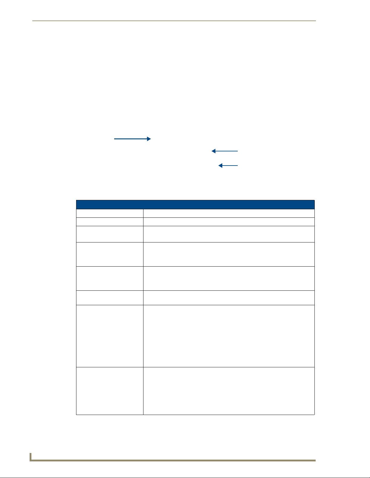
the LED while in sleep mode is enabled:
Navigation Wheel behavior in each Power Mode
Power Mode Power
Status
Awake (Full On) Battery
Power
Awake (Full On) External
Power
Awake (Full On) Charging N/A N/A BLINK BLINK
Sleep (Display
Off)
Sleep (Display
Off)
Sleep (Display
Off)
Battery
Power
External
Power
Charging 1. Display TimeOut
Enters Mode By - Exits Mode By - LED Behavior
(Sleep Blink
Setting)
Enabled Disabled
N/A N/A ON ON
N/A N/A ON ON
1. Display TimeOut
setting reached
2. Sleep Send
Command
1. Display TimeOut
setting reached
2. Sleep Send
Command
setting reached
2. Sleep Send
Command
1.Touch display
2. Press
Navigation Wheel
3. Press
Navigation Wheel
center
4. Apply External
Power
5. WakeUp Send
Command
1. Touch display
2. Press
Navigation Wheel
3. Press
Navigation Wheel
center
4. Apply External
Power
5. WakeUp Send
Command
1. Touch Display
2. Press
Navigation Wheel
3. Press
Navigation Wheel
center
4. Apply External
Power
5. WakeUp Send
Command
OFF OFF External
OFF OFF
BLINK OFF
Notes
Power will
transition
device to
Display On
Mode.
6
MVP-5200i Modero Viewpoint Widescreen Touch Panel
Page 15

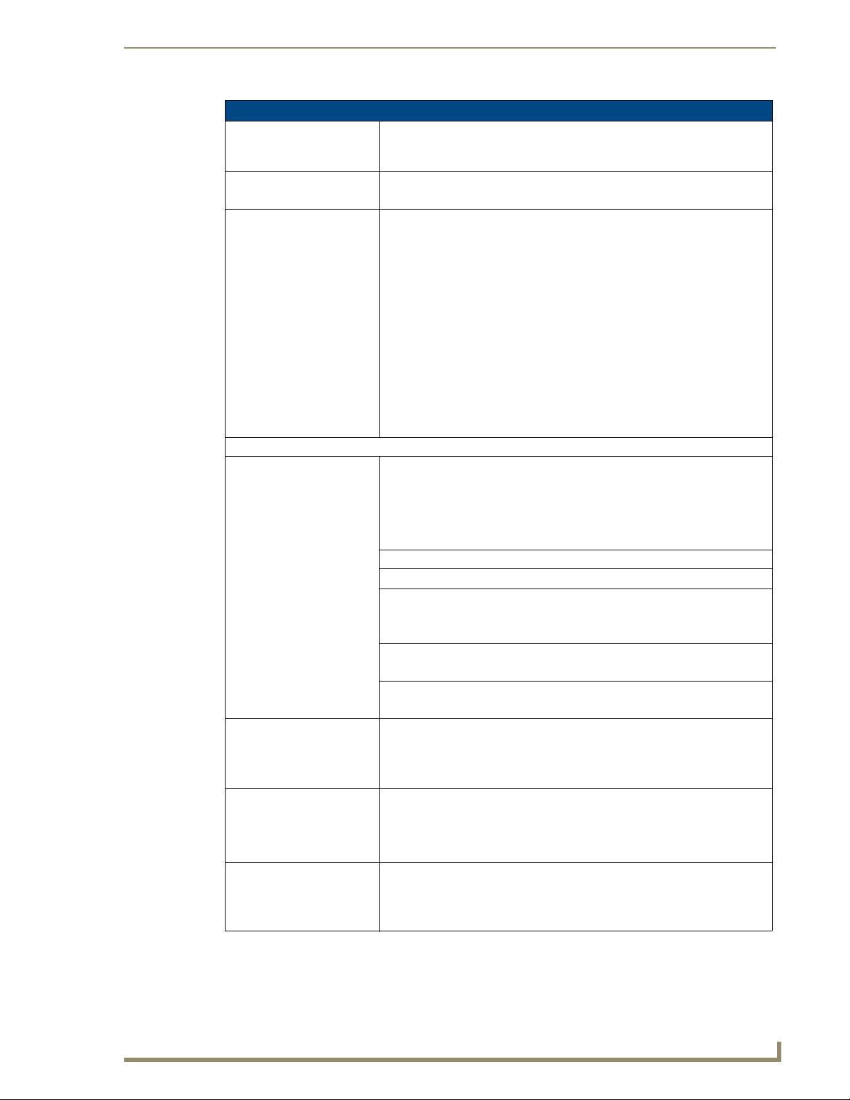
Navigation Wheel behavior in each Power Mode (Cont.)
Power Mode Power
Status
Stand By
(Display Off,
Electronics
halted)
Stand By
(Display Off,
Electronics
halted)
Stand By
(Display Off,
Electronics
halted)
Shut Down (Off) Battery
Shut Down (Off) External
Shut Down (Off) Charging N/A Same as Sleep
Battery
Power
External
Power
Charging N/A Same as Sleep
Power
Power
Enters Mode By - Exits Mode By - LED Behavior
Enabled Advanced
Power Management
1. Display TimeOut
setting reached
2. Sleep Send
Command
N/A Same as Sleep
1. Panel Shutdown
setting reached
2. Panel Shutdown
button pressed
3. Navigation Wheel
button held
N/A Same as Sleep
1. Apply External
Power
2. Touch Display
3. WakeUp Send
Command
Mode
Mode
1. Apply External
Power
2. Press and hold
Navigation Wheel
button
Mode
Mode
Introduction
Notes
(Sleep Blink
Setting)
Enabled Disabled
Off OFF External
Power will
transition
unit to
Sleep Mode
in < 10
seconds.
OFF OFF
OFF OFF
OFF OFF External
Power will
transition
unit to
Awake
Mode after
boot up
OFF OFF
OFF OFF
The navigation wheel may also be programmed to initiate specific commands. For more information,
please see the Programming section on page 103.
Intercom Microphone
The MVP-5200i contains a built-in microphone above the upper lefthand corner of the touch screen for
video and audio conferencing capabilities. This microphone is concealed by the casing.
Stylus
The MVP-5200i comes with a unique touchscreen stylus that slides into a storage groove on the right
side of the device when not in use. Replacement styluses may be ordered in a 3-pack (FG5966-30-xx)
from www.amx.com.
Kick Stand
Since the MVP-5200i device is designed to be a unit used away from its charging station, it has an
extendable "kickstand" on the back of the unit (FIG. 2). This may be opened by physically lifting the free
end of the kick stand away from the device. The device may then be propped up on a flat surface and
accessed in a normal fashion.
MVP-5200i Modero Viewpoint Widescreen Touch Panel
7
Page 16

Introduction
Audio/Video Capabilities
The MVP-5200i has the capability of displaying multiple JPEG and PNG files at one time. The device
also supports streaming motion JPEG video (of the sort used by many IP and Web cameras), as well as
MP3 and WAV audio files.
Power Management
The MVP-5200i utilizes a dual voltage external power supply. It may be recharged through the supplied
PS3.0 Power Supply (FG423-30), as well as through the MVP-TCS-52 Table Charging Station
(FG5966-1X) or the MVP-WCS-52 Wall Charging Station (FG5966-1X). For more information, see the
Accessories section on page 9 for details.
Although the MVP-5200i unit is equipped with a mini-USB port, the device cannot be
powered through the USB port. The port is only used for uploading firmware.
When not in active use, the MVP-5200i conserves battery life between chargings. In its Sleep Mode, the
device’s entire system is shut down, with only wakeup systems powered to detect incoming commands
or touch panel contact. Pressing any of the compass points on the navigation wheel will return the device
to its Active Mode,
For more information on the battery, see the Battery Life and Replacement section on page 157.
Cleaning the Touch Overlay, Case, and Navigation Wheel
Always use a clean cotton cloth and a spray bottle containing water or a vinegar-based cleaner to clean
the MVP-5200i, as alcohol-based cleaners can damage the device’s touch screen overlay. Do not
directly spray the device: instead, spray the cloth to clean the touch screen overlay and navigation
wheel. Do NOT use an abrasive of any type to clean the MVP-5200i, as this may permanently damage or
remove the device’s finish.
8
MVP-5200i Modero Viewpoint Widescreen Touch Panel
Page 17
Accessories
Table Charging Station
The MVP-5200i device comes with the MVP-TCS-52 Table Charging Station (FG5966-1X) (FIG. 5),
which acts both as a charging station and a direct power connection. The charging station is available in
either white (FG5966-10) or black (FG5966-11).
Accessories
FIG. 5 MVP-TCS-52-GB Table Charging Station - Front
MVP-TCS-52 Specifications
Dimensions (HWD): • 8.0” x 4.75” x 3.5” (20.32cm x 12.07cm x 8.89cm)
Weight: • .65 lbs (.29 kg)
Rear Connector: • 5-pin charging connector on bottom of charging cradle.
Operating/
Storage
Environments:
Included
Accessories
Other AMX
Equipment:
• Operating Temperature: 0° C (32° F) to 40° C (104° F)
• Operating Humidity: 20% - 85% RH
• Storage Temperature: -20° C (-4° F) to 60° C (140° F)
• Storage Humidity: 5% - 85% RH
• MVP-TCS-52 Table Charging Station Quick Start Guide
(93-5966-02)
• PS3.0 Power Supply (FG423-44)
• MVP-5200i Modero Viewpoint Widescreen Touch Panel -Gloss Black
(FG5966-01)
• MVP-5200i Modero Viewpoint Widescreen Touch Panel - Gloss White
(FG5966-02)
• MVP-WCS-52: Wall Charging Station (FG5966-1X)
Powering the MVP-TCS-52
The MVP-TCS-52 uses a PS3.0 power supply (included with the MVP-5200i touch panel or available
separately from www.amx.com) to provide direct power for the MVP panel both for standard functions
and for charging its internal battery.
1. Connect the terminal end of the PS3.0 power supply to the PWR connector on the bottom of the
MVP-TCS-52.
2. To prevent wear on the power supply cord and assure that the device’s base is in full contact with the
table surface, press the cord into the locking groove running across the bottom of the device.
3. Provide power to the MVP-TCS by connecting the PS3.0 cord to an external power source.
MVP-5200i Modero Viewpoint Widescreen Touch Panel
9
Page 18

Accessories
4. Place the touch panel in the Charging Station cradle (FIG. 6), guiding it into place with the locking
grooves on each side of the cradle (FIG. 7). When fully seated, the touch panel’s charging station
connector should be in contact with the Charging Station’s charger pins.
MVP-5200i device
Table Charging
Charging station
rear support
FIG. 6 MVP-5200i in MVP-TCS-52-GB Table Charging Station
Station
Connections and Wiring
The PS3.0 is used to supply power to the MVP-5200i by routing incoming power through the connector
pins and charge the device’s internal battery
Recharging
To recharge the MVP-5200i, slide the device into the Table Charging Station cradle bottom-first and
make sure the device is fully seated in the Charging Station. The charger pins in the bottom of the cradle
(FIG. 7) must be in contact with the connector on the bottom of the MVP-5200i for it to start recharging.
The MVP panel will stop recharging automatically once the battery has achieved its maximum charge.
Charging Station cradle
Charger pins
FIG. 7 MVP-TCS-52-GW Table Charging Station - Rear
Cleaning the MVP-TCS-52
You should clean the Table Charging Station after each day’s use to maintain the device’s appearance.
Always use a clean cotton cloth and a spray bottle containing water or a vinegar-based cleaner, as
alcohol-based cleaners can damage the device. Do not directly spray the device: instead, spray the cloth
to prevent moisture from collecting on the charger pins. Do NOT use an abrasive of any type to clean the
Table Charging Station, as this may permanently damage or remove the device’s finish.
10
MVP-5200i Modero Viewpoint Widescreen Touch Panel
Page 19
Accessories
Wall Charging Station
The optional MVP-WCS-52 Wall Charging Station (FG5966-1X) offers the same recharging and
connection features as the Table Charging Station, with the advantage of being placed within accessible
locations where the table station is either inconvenient or impractical (FIG. 8). The Wall Charging
Station is available in either white (FG5966-13) or black (FG5966-12).
MVP-WCS-52
MVP-5200i-GB
Security Release button
FIG. 8 MVP-WCS-52-GB Wall Charging Station - Front
The features of the MVP-WCS-52 include:
Full charging of a docked MVP-5200i in approximately 4.5 hours
Touch panel code lock for security
Integrated docking alignment guides for easy docking
Panel eject design with mechanical or electronically controlled capabilities.
.
MVP-WCS-52 Specifications
Dimensions (HWD): • 8.375" x 6.09" x 2.19" (21.27 cm x 15.46 cm x 5.56 cm)
Note: Always use the cutout/installation dimensions for the MVP-WCS-52 when
installing this unit into various surfaces. This SP engineering drawing is available
online at www.amx.com.
Power Requirements: • 3 A @ 12 VDC (Class II listed power supplemented)
Startup Power
Requirements
Weight: • Without box: 0.85 lbs (0.39 kg)
Available Colors: • MVP-WCS-52-GW (White) - FG5966-13
• Total: 1.7A
• Charging: 1.1A
• Ejection: 0.6A
• With box: 1.30 lbs (0.59 kg)
• MVP-WCS-52-GB (Black) - FG5966-12
MVP-5200i Modero Viewpoint Widescreen Touch Panel
11
Page 20
Accessories
MVP-WCS-52 Specifications
Front Panel
Components:
Operating/Storage
Environments:
Included Accessories • MVP-WCS-52 Wall Charging Station Quick Start Guide (93-5966-12)
Other AMX Equipment: • MVP-TCS-52: Table Charging Station (FG5966-1X)
• Securing Magnets: Prevent MVP touch panel from falling free during ejection.
• Security Latch: Adds the primary layer of security when mounting an MVP touch
panel. When the device is inserted, this latch grabs onto the rear of the touch
panel and secures it to prevent it from being removed.
• Interface Connector Pins: A set of retractable pins (male) that connect to the
underside MVP connector strip. This connection provides both communication
and power between the touch panel and the MVP-WCS-52.
• Support Cradle: This retractable mechanism supports a resting MVP panel and
allows a user to either insert or remove a connected MVP panel.
• Security Release pushbutton: Located on the front of the unit, this pushbutton
toggles an on-screen security keypad (if security is enabled).
- Entering the correct release code allows the MVP-WCS-52 to release the
touch panel from the security latch.
• Operating Temperature: 0° C (32° F) to 40° C (104° F)
• Operating Humidity: 20% - 85% RH
• Storage Temperature: -20° C (-4° F) to 60° C (140° F)
• Storage Humidity: 5% - 85% RH
• Wallmount plastic back box (62-5966-12)
• MVP-WCS-52 Installation Kit - Black (KA 5966-01bl)
• MVP-WCS-52 Installation Kit - White (KA 5966-01wh)
• Wallmount Metal Rough-In Box (FG037-11)
• MVP-5200i Modero Viewpoint Widescreen Touch Panel -Gloss Black
(FG5966-01)
• MVP-5200i Modero Viewpoint Widescreen Touch Panel - Gloss White
(FG5966-02)
• PS3.0 Power Supply (FG423-30)
The MVP-5200i touch panel remains locked in the MVP-WCS-52 until unlocked by the user. This may
be done by entering an appropriate password (please refer to the Password Settings Page section on
page 90 for more information), or by pressing the Security Release button on the front of the device in
emergencies. The station ejects the device top first (FIG. 9). The device uses two neodymium rare-earth
magnets to keep the MVP-5200i from falling out of its cradle when the touch panel is angled forward.
12
MVP-WCS-52-GW Wall Charging Station - Side view
FIG. 9
Wall Charging Station
MVP-5200i
Security Release button
MVP-5200i Modero Viewpoint Widescreen Touch Panel
Page 21

Accessories
Unlocking the touch panel
Once placed within the Wall Charging Station, the MVP-5200i remains secured until the user unlocks it.
A ten-second lag betwen the touch panel being placed in the Wall Charging Station and thesecurity
feature enabling allows the user to remove the touch panel if it is accidentally put into the device. To
release the touch panel from the Wall Charging Station:
1. Press the Security Release button.
2. A password keypad will pop up on the MVP-5200i screen. Enter a password in the password keypad
and press Enter.
3. Wait for the Wall Charging Station to pivot the touch panel away from the wall.
4. The device will remain in the ejected position until the MVP-5200i is removed. Wait until the
device’s ejection door has completely withdrawn before re-installing the MVP-5200i.
Unique passwords may be entered for up to four unique users as well as the
administrator. For more information on setting passwords, please refer to the
Password Settings Page section on page 90.
Recharging
To recharge the MVP-5200i:
1. Slide the device into the Wall Charging Station cradle bottom-first and make sure the device is fully
seated in the Charging Station.
2. Press the top of the MVP-5200i back until it clicks. The touch panel is now locked into the Charging
Station, and the station will automatically charge the device’s battery. (Please refer to the Battery
Settings Page section on page 60 to check on the battery charge status.)
3. To release the touch panel, unlock the touch panel and wait for the Wall Charging Station to pivot
the touch panel away from the wall.
MVP-5200i Modero Viewpoint Widescreen Touch Panel
13
Page 22

Accessories
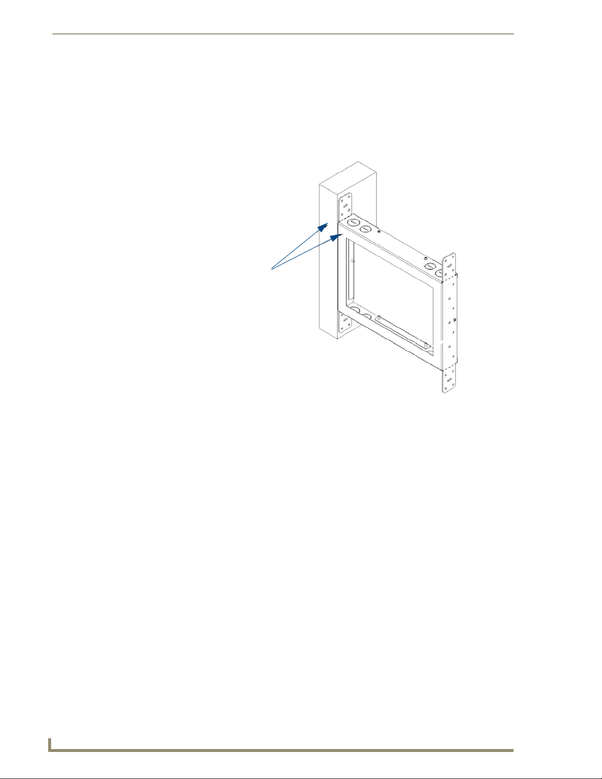
Installing the MVP-WCS-52
Since the Wall Charging Station is intended to be affixed to a wall or other permanent structure, care
must be taken to ensure its proper installation to prevent potential damage to the MVP-5200i placed
within.
Other than wall installation tools, the only tool required for this installation is a #1
Phillips screwdriver.
Installing the plastic Back Box
The plastic back box has two knockouts at the top of the box and four (4) lockdown wings attached to the
box with Phillips-head screws. For ease of installation, the interior of the box contains an "UP" arrow
pointing to the knockouts. The Metal Rough-In Box does not have to be installed beforehand, but it
offers an extra level of support.
To install the Plastic Back Box:
1. Cut a hole into the wall or surface intended to hold the box. The outer lip of the box is sized 8.69
inches (220.66mm) long and 6.0 inches (152.4mm) high, so the hole should be at least 1/4" (6.4mm)
smaller in each dimension (FIG. 10).
8.25"
8.25"
(209.55mm)
(212.7mm
5.56"
5.56"
(141.29mm)
(141.29mm)
8.25"
8.25"
(209.55mm)
(212.7mm)
FIG. 10 Recommended cutout for plastic back box
Make sure to measure the size of the intended hole before starting to cut it.
5.56"
5.56"
(141.29mm)
(141.29mm)
14
2. Select the knockout to be removed from the top of the box. The box has two knockouts, at the top
left and the top right.
MVP-5200i Modero Viewpoint Widescreen Touch Panel
Page 23
Accessories
To assist with wiring, and to avoid mechanical stresses on the wire and the
mechanism of the Wall-Mounted Charging Station, the top right knockout is preferred
for use.
3. Run the power cable through the knockout into the box. Pull out about six inches (15.25cm) of cable
into the box to facilitate installation of the MVP-WCS-52.
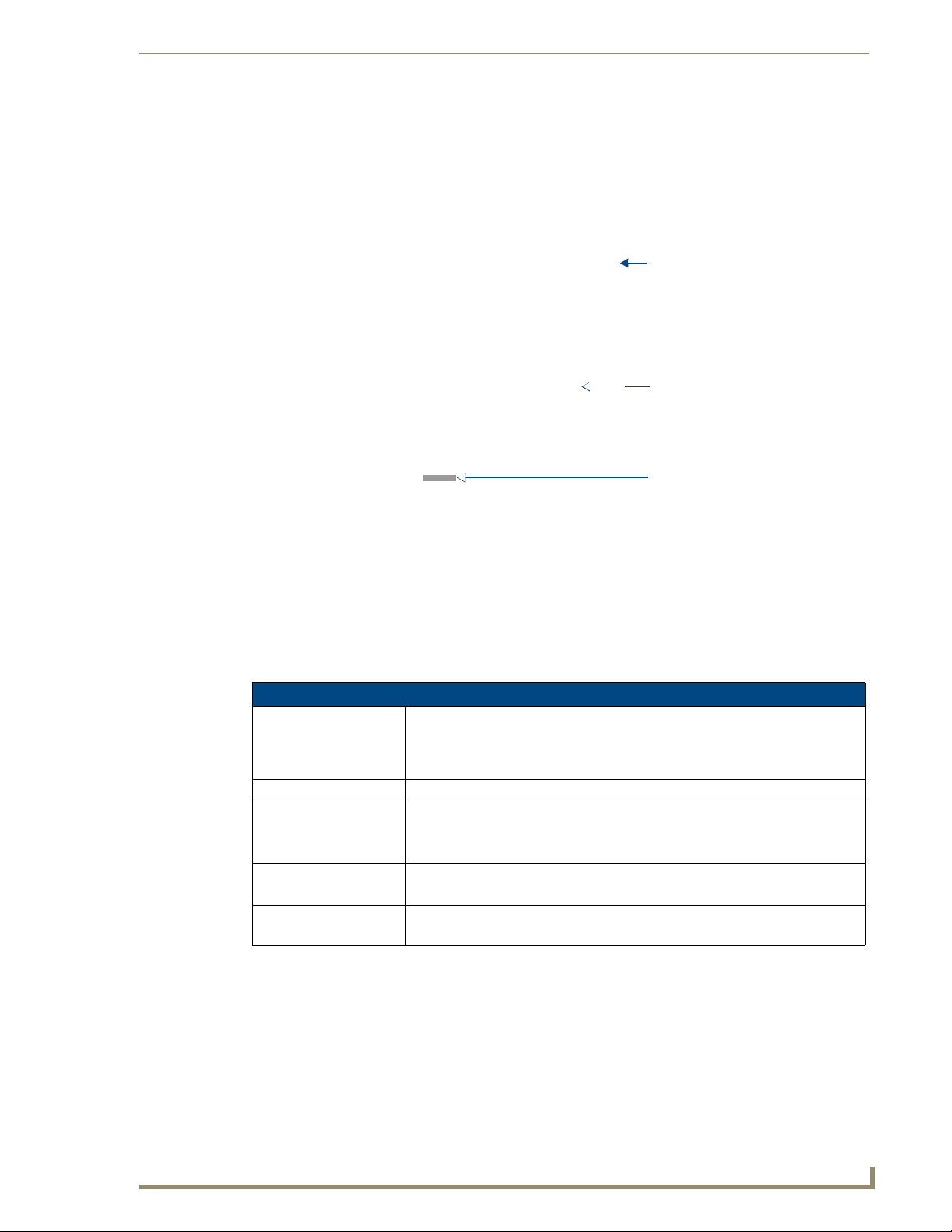
4. Slide the plastic back box into the hole, being careful not to twist or pinch the cable, and set it flush
with the wall (FIG. 11). Make sure that all of the lockdown wings are folded into their slots before
attempting to insert the box. For ease of installation, the inside of the box has the direction "UP"
labeled for reference.
All lockdown wings folded flat during installation
Note Orientation Designator
FIG. 11 Installation of plastic back box
5. Extend the wings on the sides of the box by tightening the screws inside the box. Not all of the
wings must be extended to lock the box in place, but extending a minimum of the top and bottom
wings is highly recommended. Apply enough pressure to the screw head to keep the box flush with
the wall: this ensures that the wing will tighten up against the inside of the wall.
Make absolutely certain that the box is in its intended position. Once the box
lockdown wings are extended within the box’s hole within the wall, removing the box
will be extremely difficult without damaging the wall in the process.
The maximum recommended torque to screw in the wings on the plastic back box is
105 IN-OZ [74 N-CM]. Applying excessive torque while tightening the wing screws,
such as with powered screwdrivers, can strip out the wings or damage the plastic
back box.
6. Prepare the captive wires for the 2-pin 3.55 mm mini-captive wire connector used for the MVP-
WCS-52’s power supply:
Preparing and connecting the captive wires requires the use of a wire stripper and
flat-blade screwdriver.
MVP-5200i Modero Viewpoint Widescreen Touch Panel
15
Page 24

Accessories
Strip 0.25 inch (6.35 mm) of wire insulation off all wires.
Insert each wire into the appropriate opening on the connector.
Turn the screws clockwise to secure the wires in the connector. Do not over-torque the screws;
doing so can bend the seating pins and damage the connector.
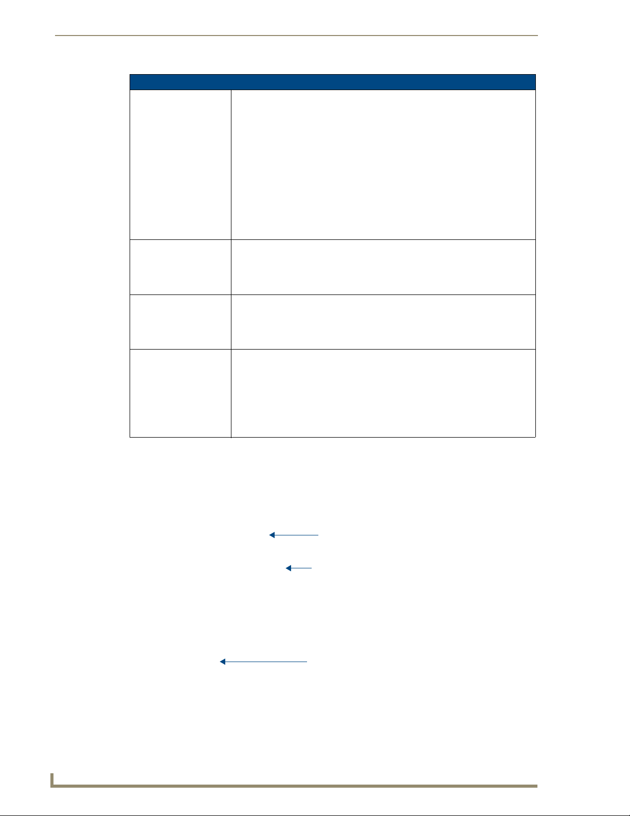
7. Secure the power cable to the device, using either of the two tie-wrap anchors included in the
Installation Kit at the top rear of the device (FIG. 12). Point the head of each tie wrap toward the
center of the device.
Tie-Wrap Anchors
Mini-Captive Wire
Connector Plug
(female)
FIG. 12 MVP- WCS-52 - Rear
8. Firmly seat the mini-captive wire connector to the power connector on the device.
9. Firmly seat the device against the box. Make sure that the tab connector at the top of the device is
locked into the box.
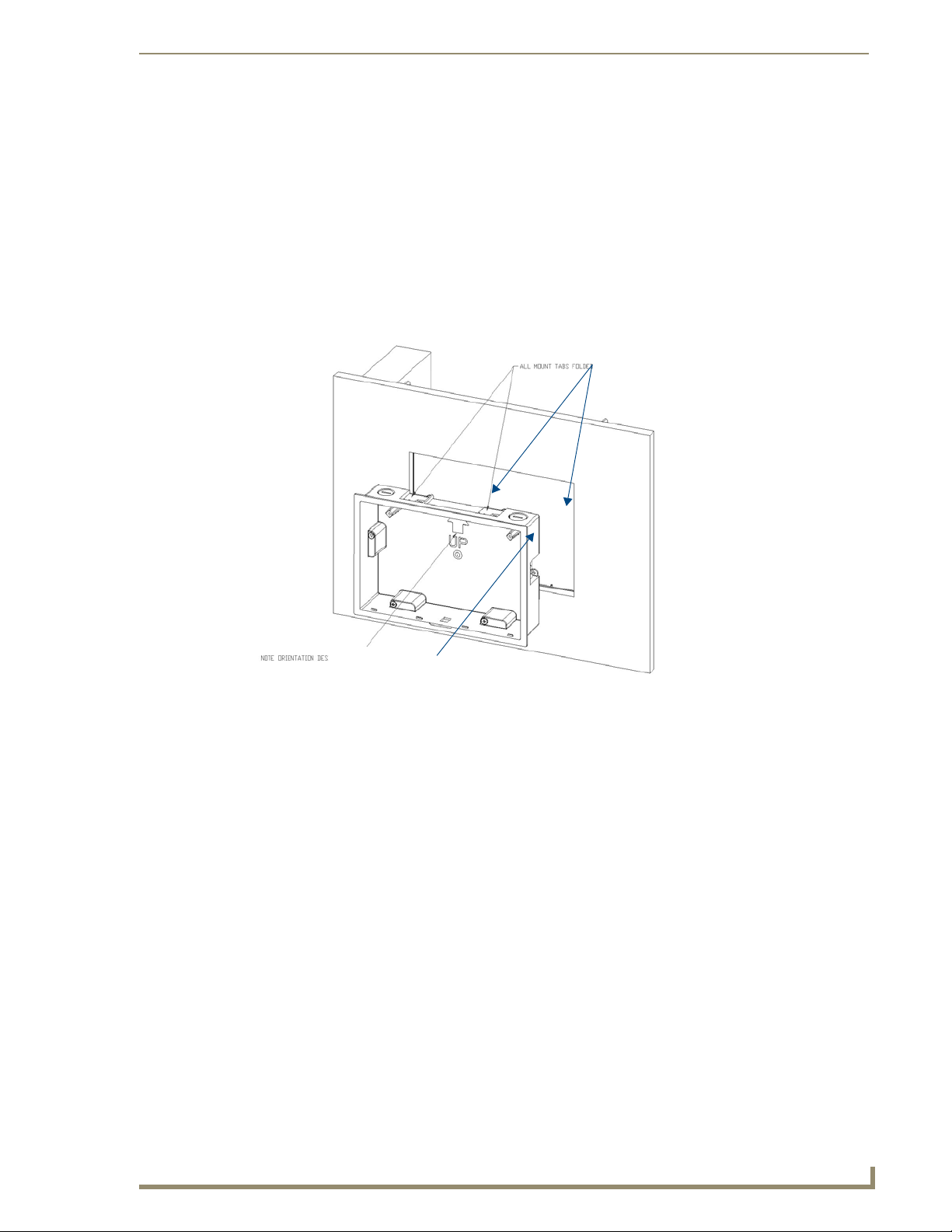
10. Insert the two installation screws from the MVP-WCS-52 Installation Kit into the screw holes in the
interior compartment of the device and tighten them to anchor the device to the box (FIG. 13).
16
MVP-5200i Modero Viewpoint Widescreen Touch Panel
Page 25
Screw holes
Accessories
Plastic back box
Neodymium magnets
MVP-WCS-52
Rubber feet
FIG. 13 Installation of MVP-WCS-52
For ease of installation, put each screw on a neodymium magnet in the device’s
interior compartment to keep them on hand until they are needed.
11. After fully seating the screws, wipe down the area around the screw holes with the alcohol prep pad
from the Installation Kit. Take a rubber foot and remove its adhesive backing. Put the foot, adhesiveside down, in the slot surrounding the screw hole in the Wall Charging Station. Press down firmly to
remove any air bubbles from underneath the foot.
12. Install an MVP-5200i device by placing it into the interior compartment bottom-first. Press the top
of the touch panel until it is flush with the Wall Charging Station. The neodymium magnets will
hold it in place.
13. To remove the MVP-5200i, unlock the touch panel (see the Unlocking the touch panel section on
page 13 for more information) and wait for the touch panel to pull away from the Wall Charging
Station. Once it has been released, grip it by the top of the device, and pull it free from the Charging
Station.
MVP-5200i Modero Viewpoint Widescreen Touch Panel
17
Page 26
Accessories
Installing the Optional Metal Rough-In Box
The optional metal rough-in box (FG037-11) is 10 inches (25.40cm) wide at its widest dimension (wider
than the bezel of the Wall Charging Station), and is only intended for pre construction installations
(FIG. 14). The Metal Rough-In Box is used in conjunction with the Wall Charging Station’s plastic back
box. The Metal Rough-In Box must be located behind 3/8" (0.95cm) to 3/4" (1.91cm) of wall/mounting
surface material.
Install front surface of box
flush with surface of wall stud
FIG. 14 Typical metal Rough-In Box Installation
The metal rough-in box bears a wing on each corner which is intended to bridge gaps between studs and/
or spacers. These wings may be bent carefully in order to fit a particular gap, but may not be so bent as to
allow the box to hang in a vertical position. Once placed in the desired position, put at least one screw
through each wing into the adjoining stud or spacer to secure it.
The interior of the box contains a set of holes on either side, as well as top and bottom, for standard 1/4inch screws. Use these holes to anchor the box to its adjoining studs or spacers.
Ensure that the metal rough-in box is flush with the 2x4 studs. Any overhang will
affect the installation of the covering sheetrock, as well as affect the placement of the
Plastic Back Box.
The box has two sets of knockouts in the top and bottom, one of the set for US wiring and one for
international wiring.
Make sure that the power cable has been pulled through the metal rough-in box by
the resident electrician before continuing the installation.
After completing the installation of the metal rough-in box, install sheet rock or other wall material over
the box, cut a hole matching the size of the inside diameter in the sheet rock, and clean out all dust before
proceeding with the installation of the plastic back box.
18
MVP-5200i Modero Viewpoint Widescreen Touch Panel
Page 27

Accessories
Other MVP-WCS-52 installations
The Wall-Mounted Charging Station is designed to be installed in various different locations, such as
into the face of a wooden podium or the top of a table. Depending upon the ability to wire it to a power
source, Wall-Mounted Charging Stations may be installed on vertical or horizontal surfaces composed of
such materials as wood, brick, and glass.
Installing a Wall-Mounted Charging Station into a solid wall thicker than a standard thickness of
sheetrock is possible, but requires special preparation. If installing into a solid wall of concrete or rock, a
recess must be chiselled or cut out to match the size of the device. The box is sized 8.375 inches
(21.27cm) long and 5.75 inches (14.60cm) high, so the hole should be at least 1/4" (0.64cm) smaller in
these dimensions. To facilitate the full range of movement of the device’s components, the recess must
be at least 2.69 inches (6.83cm) deep.
Ensure that the power cable has been installed in the wall and is accessible by the
installer before chiseling out the recess.
Instead of using the lockdown wings to secure the Plastic Back Box, standard
concrete screws may be inserted through the screw holes after removing the
lockdown wings. However, drill the concrete screw holes into the wall before setting
the screws into the box, as excessive torque applied to the screws will damage the
box. To avoid this, the box may be installed with adhesive. Test an unobtrusive spot
on the back of the box with a sample of the adhesive to check for any adverse
reactions before installing the device.
MVP-5200i Modero Viewpoint Widescreen Touch Panel
19
Page 28

Accessories
20
MVP-5200i Modero Viewpoint Widescreen Touch Panel
Page 29
Configuring Communication
All control for a MVP-5200i touch panel is established through a NetLinx Master. Communication
between the MVP and the Master consists of using either Wireless Ethernet (DHCP, Static IP) or USB.
References to Ethernet in this manual focus on the use of Wireless Ethernet via the MVP’s WiFi Card.
Configuring Communication
Before commencing, verify you are using the latest NetLinx Master and
Modero panel-specific firmware. Verify you are using the latest versions of AMX’s
NetLinx Studio and TPDesign4 programs.
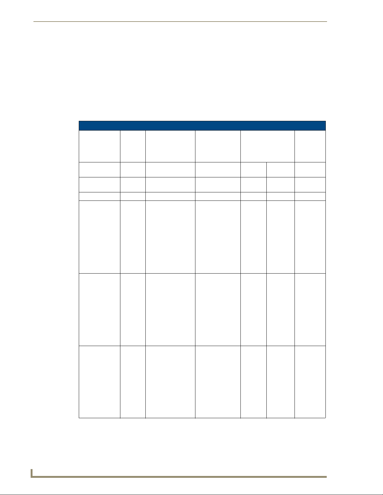
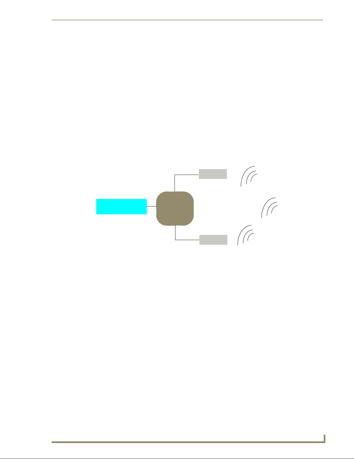
In the example below (FIG. 15), three MVP-5200i devices are shown at varying distances from the two
WAP gateways. As with any other WAP network, the gateways are spaced so as to allow a maximum
wireless coverage for the three devices.
Panel 1
Panel 2
Panel 3
Network Master
FIG. 15 System Deployment Diagram
802.11g WAP
IP
Network
802.11g WAP
When initially installing the MVP-5200i, some basic configuration items, including network settings and
NetLinx settings, will need to be set. For more information, refer to the Protected Setup Pages section on
page 61.
The MVP-5200i defaults to Ethernet and Auto mode for its Master connection.
MVP-5200i Modero Viewpoint Widescreen Touch Panel
21
Page 30

Configuring Communication
IR Communication
In certain situations, the MVP-5200i may be used as an infrared remote device for other AMX
controllers. The device can transmit IR over 20 feet (6.10 m) from the panel at frequencies of 38KHz,
455KHz, and 1.2MHz. IR receivers and transmitters on G4 panels share the device address number of
the panel.
The MVP-5200i includes an IR transmitter for communication between the device and the NetLinx
Master and between separate devices. The transmitter is located behind the IR Emitter Panel on the rear
of the device (FIG. 16).
IR Emitter Panel
FIG. 16 IR transmitter window on the MVP-5200i-GW
22
MVP-5200i Modero Viewpoint Widescreen Touch Panel
Page 31

Configuring Communication
Modero Setup and System Settings
All AMX Modero panels, including the MVP-5200i, feature on-board Setup pages. Use the options in
the Setup pages to access panel information and make various configuration changes.
Accessing the Setup and Protected Setup Pages
At any time, press down and hold the center button of the navigation wheel for 3-5 seconds. This
1.
opens a release notice to release the button immediately to open the Setup page (FIG. 17).
FIG. 17 Setup page
2. Press the Protected Setup button. This opens a keypad for entry of the password to allow access to
the Protected Setup page (FIG. 18). Enter the device’s password and press Done to proceed.
FIG. 18 Protected Setup page
The default password for the Protected Setup page is 1988, but this may be changed
at any time.
For more information on the Setup and Protected Setup pages, refer to the Setup Pages section on
page 51 and the Protected Setup Pages section on page 61.
MVP-5200i Modero Viewpoint Widescreen Touch Panel
23
Page 32

Configuring Communication
Setting the Panel’s Device Number
In the Protected Setup page:
1. Press the Device Number field in the Device ID section to open the Device Number keypad.
2. Enter a unique Device Number assignment for the device, and press Done to return to the Protected
Setup page. The Device Number range is 1 - 32000, and the default is 10001.
3. Press Reboot to reboot the device and apply the new Device Number.
Wireless Settings - Wireless Access Overview
DHCP
When choosing DHCP, a DHCP server must be accessible before the fields are populated.
If the SSID (Network Name) and WEP fields have not previously been configured, the
Wireless Settings page will not work until the panel is rebooted.
The parameters of the wireless card must be set before selecting Ethernet as the Master Connection
Type. The Wireless Access Point communication parameters must match those of the pre-installed
wireless CF card inside the device.
MVP touch panels connect to a wireless network through their use of the pre-installed AMX 802.11g
wireless interface card. This allows users to communicate with a Wireless Access Point (WAP). The
WAP communication parameters must match those of the pre-installed wireless interface card installed
within the panel. This internal card transmits data using 802.11x signals at 2.4 GHz. For a more detailed
explanation of the new security and encryption technology, refer to the Appendix B: Wireless
Technology section on page 166.
For more information on utilizing the AMX Certificate Upload Utility in conjunction with the EAP
security, refer to the AMX Certificate Upload Utility section on page 173.
24
MVP-5200i Modero Viewpoint Widescreen Touch Panel
Page 33

Configuring Communication
Configuring Wireless Network Access
The first step in connecting the MVP-5200i to a wireless network is to configure the wireless
communication parameters within the device’s Wireless Settings page. This page only configures the
card to communicate to a target WAP: the device must still be directed to communicate with the
correct Master. This "pointing to a Master" is done via the System Settings page, which allows
configuration of the IP Address, System Number and Username/Password information assigned to the
target Master.
Step 1: Configure the Device’s Wireless IP Settings
The first step to a successful setup of the internal wireless card is to configure the IP Settings section on
the Wireless Settings page. This section configures the communication parameters from the MVP panel
to the web.
Wireless communication using a DHCP Address
In the Protected Setup page:
1. Select Wireless Settings. Wireless communication is set within the IP Settings section of this page
(FIG. 19).
FIG. 19 Wireless Settings page (IP Settings section)
2. Toggle the DHCP/Static field from the IP Settings section until the choice cycles to DHCP. This
action causes all fields in the IP Settings section, other than Host Name, to be greyed-out.
DHCP will register the unique factory-assigned MAC Address on the panel, and once
the communication setup process is complete, assign IP Address, Subnet Mask, and
Gateway values from the DHCP Server.
3. Press the optional Host Name field to open the Host Name keyboard and enter the host name
information.
4. Press Done after assigning the alpha-numeric string of the host name.
5. The remaining greyed-out fields in the IP Settings section cannot be altered. Once the panel is
rebooted, these values are obtained by the unit and displayed in the DNS fields after power-up.
MVP-5200i Modero Viewpoint Widescreen Touch Panel
Wireless Access Point
Site Survey Button
25
Page 34

Configuring Communication
This information can be found in either the Workspace - System name > Define
Device section of the code that defines the properties for the panel, or in the Device
Addressing/Network Addresses section of the Tools > NetLinx Diagnostics dialog.
6. Set up the security and communication parameters between the wireless card and the target WAP by
configuring the Wireless Settings section on this page. Refer to Step 2: Configure the Card’s
Wireless Security Settings section on page 29 for detailed procedures to setup either a secure or
insecure connection.
Wireless communication using a Static IP Address
From the Protected Setup page, press the Wireless Settings button to open the Wireless Settings
1.
page. Wireless communication is set within the IP Settings section of this page (FIG. 19).
Check with your System Administrator for a pre-reserved Static IP Address to be
assigned to the panel. This address must be obtained before continuing with the
Static assignment of the panel.
2. Toggle the DHCP/Static field from the IP Settings section until the choice cycles to Static.
The IP Address, Subnet Mask, and Gateway fields then turn red, noting that they are now usereditable.
3. Press the IP Address field to open a keyboard and enter the Static IP Address provided by the
System Administrator. Press Done after entering the IP address information and repeat the same
process for the Subnet Mask and Gateway fields.
4. Press the optional Host Name field to open the keyboard and enter the Host Name information.
Press Done after assigning the alpha-numeric string of the host name.
5. Press the Primary DNS field to open a Keyboard, enter the Primary DNS Address (provided by the
System Administrator) and press Done when compete. Repeat this process for the Secondary DNS
field.
6. Press the Domain field to open a Keyboard, enter the resolvable domain Address (this is provided
by the System Administrator and equates to a unique Internet name for the panel), and press Done
when complete.
7. Set up the security and communication parameters between the wireless card and the target WAP by
configuring the Wireless Settings section on this page. Refer to the following section for detailed
procedures to set up either a secure or unsecure connection.
26
MVP-5200i Modero Viewpoint Widescreen Touch Panel
Page 35

Configuring Communication
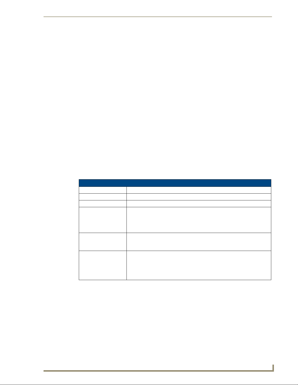
Using the Site Survey tool
This tool allows a user to "sniff out" all transmitting Wireless Access Points within the detection range of
the internal wireless card (FIG. 20). Once the Site Survey button is pressed, the device displays the Site
Survey page, which contains the following categories:
Network Name (SSID) - Wireless Access Point names
Channel (RF) - Channel currently being used by the WAP (Wireless Access Point)
Security Type (if detectable - such as WEP, OPEN and UNKNOWN) - security protocol
enabled on the WAP
Signal Strength - displaying None, Poor, Fair, Good, Very Good, and Excellent
MAC Address - Unique identification of the transmitting Access Point
FIG. 20 Site Survey page
To access the Site Survey Tool:
1. From the Protected Setup page, press the Wireless Settings button to open the Wireless Settings
page.
2. Press the Site Survey button. This action launches the Wireless Site Survey page, which displays a
listing of all detected WAPs in the communication range of the internal card.
The card scans its environment every four seconds and adds any new WAPs found to the list.
Every scan cycle updates the signal strength fields.
Access points are tracked by MAC Address.
If the WAP’s SSID is set as a blank, then N/A is displayed within the SSID field.
If the WAP’s SSID is not broadcast, it will not show up on the Wirel ess Netw orks
screen.
If a WAP is displayed in the list is not detected for 10 scans in a row, it is then
removed from the screen. In this way, a user can walk around a building and track
access points as they move in and out of range.
3.
Sort the information provided on this page by pressing on a column name. This moves the sorting
arrow to that column, where it may be toggled up or down.
Up arrow - indicates that the information is being sorted in an ascending order.
Down arrow - indicates that the information is being sorted in a descending order.
MVP-5200i Modero Viewpoint Widescreen Touch Panel
27
Page 36

Configuring Communication
If the panel detects more than 10 WAPs, the Up/Down arrows at the far right side of
the page become active (blue) and allow the user to scroll through the list of entries.
4. Select a desired Access Point by touching the corresponding row. The up arrow and down arrow
will be grayed out if ten or fewer access points are detected. If more are detected, then they will be
enabled as appropriate so that the user can scroll through the list.
5. With the desired WAP selected and highlighted, click the Connect button to be directed to the
selected security mode’s Settings page with the SSID field filled in. From there, either Cancel the
operation or fill in any necessary information fields and then click Save.
Selecting an Open, WEP, and WPA-PSK Access Point and then clicking Connect will open the
corresponding Settings page. For any other security mode, clicking Connect will only return to the
previous page without any information being entered.
In an Open security mode, after selection and connection to a target WAP, the SSID name of
the selected WAP is saved for the open security mode.
In a Static WEP security mode, after selection and connection to a WEP Access Point, the user
is then redirected back to the Static WEP security screen, where the SSID field is already filled
out. The user is only required to enter in the remaining WEP key settings.
A similar process occurs for WPA-PSK access points. For any other situation, the security
mode switches back to the previous page and security and connection parameters must be
entered in as usual.
28
MVP-5200i Modero Viewpoint Widescreen Touch Panel
Page 37
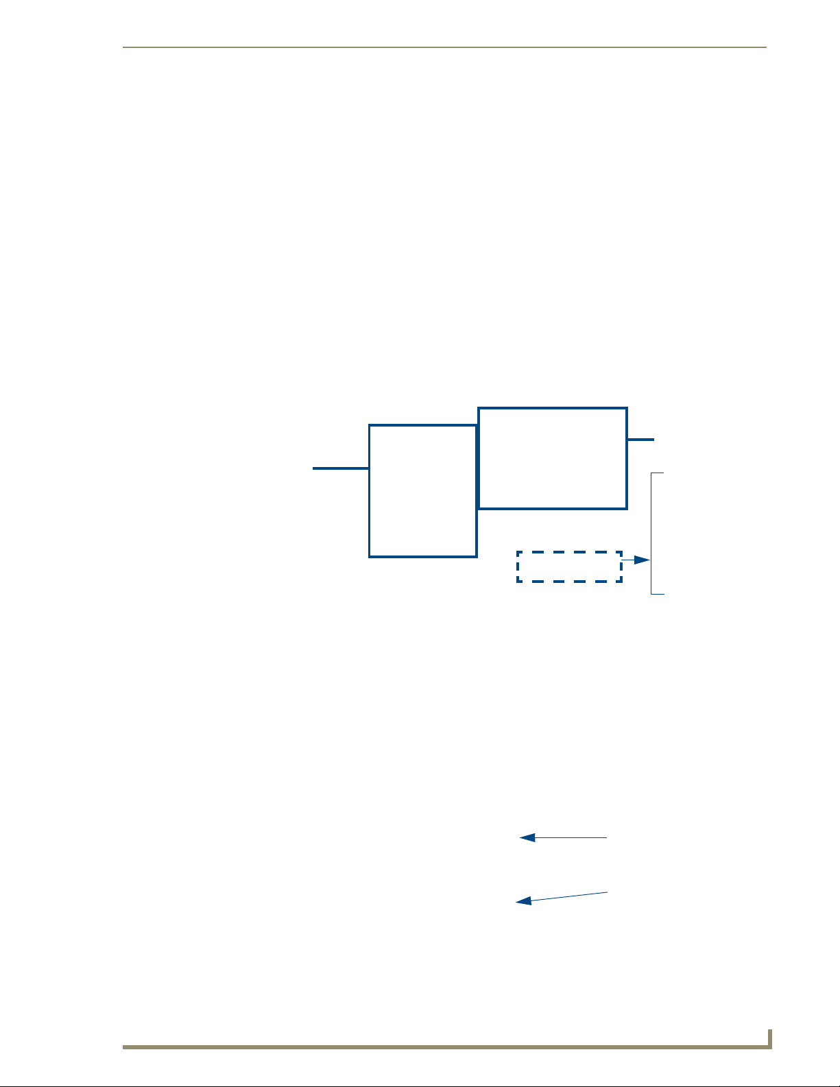
Configuring Communication
Step 2: Configure the Card’s Wireless Security Settings
The second step in setting up the wireless card is to configure the Wireless Settings section of the
Wireless Settings page. This section configures both the communication and security parameters from
the internal wireless card to the WAP. The procedures outlined within the following sections for an
802.11g card facilitate a common security configuration to a target WAP.
Refer to the Appendix B: Wireless Technology section on page 166 for more information on other
security methods.
After setting up the wireless card parameters, configure the communication parameters for the target
Master; see Step 3: Choose a Master Connection Mode section on page 35.
Configuring the device’s wireless card for unsecured access to a WEP
In the Protected Setup page:
1. Press the Wireless Settings button (located on the lower-left) to open the Wireless Settings page
(FIG. 21).
Wireless card
MVP connection
IP info
security settings
FIG. 21 Wireless Settings page (showing a sample unsecured configuration)
2. Enter the SSID information by:
Automatically filling it by pressing the Site Survey button. From the Site Survey page,
choosing an Open WAP from within the Site Survey page and then pressing the Connect
button at the bottom of the page (FIG. 22).
Select an OPEN
(unsecured) WAP
Connecting to the
WAP begins the
communication.
FIG. 22 Site Survey of available WAPS (Unsecured WAP shown selected)
Manually entering the SSID information into the appropriate fields by following steps 7
through 9.
MVP-5200i Modero Viewpoint Widescreen Touch Panel
29
Page 38

Configuring Communication
3. From within the Wireless Security section, press the Open (Clear Text) button to open the Open
(Clear Text) Settings dialog (FIG. 23). An Open security method does not utilize any encryption
methodology, but does require that an alpha-numeric SSID be entered. This method sends out
network packets as unencrypted text.
FIG. 23 Wireless Settings page - Open (Clear Text) security method
4. Press the red SSID field to display an on-screen Network Name (SSID) keyboard.
5. In this keyboard, enter the SSID name used on the target Wireless Access Point (case sensitive).
6. Click Done when complete.
7. From the Open (Clear Text) Settings page (FIG. 23), press the Save button to incorporate the new
information into the device and begin the communication process.
8. Verify the proper configuration in the fields in the IP Settings section. Refer to Step 1: Configure the
Device’s Wireless IP Settings section on page 25 for detailed information.
9. Press the Back button to return to the Protected Setup page and press the on-screen Reboot button
to save any changes and restart the device. Remember that the connection must be configured to a
target Master from the System Settings page.
10. After the panel restarts, return to the Wireless Settings page’s RF Link Info section and verify the
link quality and signal strength:
Required information:
- SSID (Network Name used by the Target WAP)
By default, this field displays the
SSID - AMX
The card should be given the SSID used by the target WAP. If this field is left blank, the unit
will attempt to connect to the first available WAP. By default, all WAP200Gs use AMX as
their assigned SSID value.
One of the most common problems associated with connection to a WAP involves an incorrect
SSID. Make sure to maintain the same case when entering the SSID information. ABC is not
the same as Abc.
The descriptions are None, Poor, Fair, Good, Ver y G o od , and Excellent (FIG. 21).
30
The signal strength field should provide some descriptive text regarding the strength
of the connection to a Wireless Access Point. If no signal or no IP Address is
displayed, configuration of the network could be required.
MVP-5200i Modero Viewpoint Widescreen Touch Panel
Page 39

Configuring Communication
Automatically setting SSID
In the Protected Setup page:
1. Select Wireless Settings.
2. Press the Site Survey button at the bottom of the page.
3. Select a WEP secured WAP from within the Site Survey page, and press the Connect button
(FIG. 24). .
Select a target
WAP with the desired
level of security
Connecting to the WAP
begins the communication
FIG. 24 Site Survey of available WAPs (Secured WAP shown selected)
4. If the security is not handled automatically, the information must be entered manually from the
Wireless Security menu.
Manually setting SSID
From the Protected Setup page:
1. Select Wireless Settings.
2. Locate the Wireless Security menu (FIG. 25).
FIG. 25 Wireless Security page
MVP-5200i Modero Viewpoint Widescreen Touch Panel
31
Page 40

Configuring Communication
3. Press the Static WEP button to open the Static WEP Settings dialog (FIG. 26).
FIG. 26 Wireless Settings page - Static WEP security method
4. Press the SSID field. From the Network Name (SSID) keyboard, enter the SSID name used by the
target Wireless Access Point (case sensitive), and press Done when finished.
5. Toggle the Encryption field (FIG. 26) until it reads either 64 Bit Key Size or 128 Bit Key Size.
The 64/128 selection reflects the bit-level of encryption security. This WEP encryption level must
match the encryption level being used on the WAP.
Requ ire d In for mati on:
- SSI D (Net wor k Nam e u sed by t he Targe t WA P)
- Encryp tion Method
- Passphrase
- WE P Key assi gn me nt
- Auth en ti catio n M et ho d
The card should be given the SSID used by the target WAP. If this field is left blank, the device
will attempt to connect to the first available WAP.
One of the most common problems associated with connection to a WAP arises because of an
improperly entered SSID. The same case must be maintained when entering this information.
ABC is not the same as Abc.
The alpha-numeric string is AMX by default, but can later be changed to any 32-character
entry. This string must be duplicated within the Network Name (SSID) field on the WAP. As an
example, if the SSID is TECHPUBS, this word and the case within must match both the
Network Name (SSID) field on the touch panel’s Network Name SSID field and on the WAP’s
Basic Wireless Configuration page.
32
WEP will not work unless the same Default Key is set on both the panel and the
Wireless Access Point. For example: if the Wireless Access Point has been set to
default key 4 (which was 01:02:03:04:05), the panel’s key 4 must be set to
01:02:03:04:05.
6. Toggle the Default Key field to choose a WEP Key value (from 1- 4) that matches what will be used
on the target. This value MUST MATCH on both devices.
These WEP Key identifier values must match for both devices.
7. With the proper WEP Key value displayed, press the Generate button to launch the WEP
Passphrase keyboard.
If the target WAP is to generate the Current Key, do not press the Generate button. Instead,
continue with Step 13.
MVP-5200i Modero Viewpoint Widescreen Touch Panel
Page 41

Configuring Communication
8. Within the WEP Passphrase keyboard (FIG. 27), enter a character string or word (such as
AMXPanel) and press Done when finished.
FIG. 27 WEP Passphrase Keyboard
For example, enter the word AMXPanel using a 128-bit hex digit encryption. After pressing
Done, the on-screen Current Key field displays a long string of characters, separated by
colons, which represents the encryption key equivalent to the word AMXPanel.
This series of hex digits (26 hex digits for a 128-bit encryption key) should be entered as the
Current Key into both the WAP and onto other communicating Modero panels by using the
WEP Key dialog (FIG. 28).
FIG. 28 WEP Key # Keyboard
9. Write down this Current Key string value for later entry into the WAP’s WEP Key field (typically
entered without colons) and into other communicating panel’s Current Key field.
10. If entering a Current Key generated either by the target WAP or another Modero panel,
within the WEP Keys section, touch the Key # button to launch the WEP Key # keyboard, enter the
characters and press Done when finished.
This Key value corresponds to the Default WEP Key number used on the Wireless Access
Point and selected in the Default Key field.
If the target Wireless Access Point does not support passphrase key generation and
has previously been setup with a manually entered WEP KEY, that same WEP key
must be manually entered on the panel.
11. The remaining Current Key and Authentication fields are greyed-out and cannot be altered by the
user.
MVP-5200i Modero Viewpoint Widescreen Touch Panel
33
Page 42

Configuring Communication
12. Verify that the fields within the IP Settings section have been properly configured. Refer to Step 1:
Configure the Device’s Wireless IP Settings section on page 25 for detailed information.
13. Press the Back button to navigate to the Protected Setup page and press the on-screen Reboot
button to save any changes and restart the panel. Remember that you will need to navigate to the
System Settings page and configure the connection to a target Master.
14. After the panel restarts, return to the Wireless Settings page to verify the Link Quality and Signal
Strength:
The signal strength field provides some descriptive text regarding the strength of the
connection to a Wireless Access Point. Configuration of the network could be
required if there is no signal or no IP Address is displayed.
Configuring multiple wireless touch panels to communicate to a target WEP
For each communicating touch panel, complete all of the steps outlined within the previous section
1.
on page 30.
2. Navigate back to the Wireless Settings page on each panel.
3. Verify that all communicating Modero panels are using the same SSID, encryption level, Default
Key #, and an identical Current Key value.
4. Repeat steps 1 - 3 on each panel. Using the same passphrase generates the same key for all
communicating Modero panels.
The descriptions are None, Poor, Fair, Good, Ver y G o od , and Excellent.
As an example, all panels should be set to Default Key #1 and be using aa:bb:cc.as the
Current Key string value. This same Key value and Current Key string should be used on the
target WAP.
34
MVP-5200i Modero Viewpoint Widescreen Touch Panel
Page 43

Configuring Communication
Step 3: Choose a Master Connection Mode
The MVP-5200i requires a decision on the type of connection to be made between it and the Master.
To establish a Master connection:
1. From the Protected Setup page, select System Settings.
2. Select Type to toggle between the Master Connection Types USB and Ethernet (FIG. 29).
A USB connection is a direct connection from the panel’s mini-USB port to a corresponding
USB port on the PC (acting as a Virtual Master).
A wireless Ethernet connection involves indirect communication from the panel to a Master
via a wireless connection to the network.
Although firmware upgrades can be conducted over wireless Ethernet, transferring
firmware KIT files over a USB connection is recommended, and only when the panel
is connected to a power supply. If battery power or the wireless connection fails
during a firmware upgrade, the panel flash file system may become corrupted.
FIG. 29 System Settings page
Ethernet over USB
The MVP-5200i device is the first G4 device to support a new Ethernet over USB driver for panel
downloads and firmware updates. This means that the device can connect to a host computer for updates
through its Mini USB port instead of through a standard Ethernet port (FIG. 30).
Mini-USB Port
FIG. 30 USB Port on the MVP-5200i
Because of its Ethernet over USB capabilities, the MVP-5200i also follows a different procedure for
downloading firmware than with other G4 devices. Firmware downloads require use of the USB
Programming Cable (FG10-5965) and a computer running Windows XP.
MVP-5200i Modero Viewpoint Widescreen Touch Panel
35
Page 44

Configuring Communication
Touch panel setup
To prepare the MVP-5200i for Ethernet for USB communication:
1. Turn on the MVP-5200i and wait for the device to finish booting up.
2. Insert the mini-USB end of the USB Programming Cable into the mini-USB port on the device.
Insert the other end into the appropriate USB port on the computer containing the files to be
downloaded.
3. If the connection goes well, the Windows XP machine will detect the device as an unsupported USB
device. It then presents a dialogue box that prompts the user for a suitable driver (FIG. 31):
FIG. 31 Found New Hardware Wizard dialogue box
4. Select Yes, this time only and click on Next.
5. In the new window:
- Select Use the following IP Address.
Under IP address, provide an IP address. Ensure that it is in the same subnet as the IP address
given to the usb0 interface on the MVP-5200i, but make sure that it has a different node
number. The IP address cannot be the same as the panel`s USB IP address.
Under Subnet mask, set the suitable subnet mask.
Click OK.
36
MVP-5200i Modero Viewpoint Widescreen Touch Panel
Page 45

6. In the next box (FIG. 32), make sure to:
Select Search for the best driver in these locations
Select Include this location in the search
Click on Browse
Select the folder that contains the 'linux.inf' file
Configuring Communication
FIG. 32 Found New Hardware Wizard Installation Options dialogue box
7. Click on Next.
8. The Windows XP machine now searches for the suitable driver (FIG. 33).
FIG. 33 Found New Hardware Wizard while searching for the driver
MVP-5200i Modero Viewpoint Widescreen Touch Panel
37
Page 46

Configuring Communication
9. Once the system finds the driver, it displays its choice (FIG. 34). Click Finish to complete the driver
installation.
FIG. 34 Completing the Found New Hardware Wizard
When an IP address is assigned to the usb0 interface on the device, Windows XP will make an attempt to
assign an IP address to the corresponding interface on the Windows side. Usually, this IP address is a
random value and in a totally different subnet. The user may set the Windows network properties for the
Ethernet over USB interface to have a specific address whenever the Windows XP system detects an
MVP-5200i with an assigned IP address.
In Windows XP:
1. From the Windows XP desktop, click on Start > Settings > Network Connections. This opens a
window listing the currently active network connections.
2. Select the connection that is specific to AMX USB Device Link.
3. Right click and select Properties.
4. In the Local Area Connection 3 Properties window (FIG. 35) under the General tab, select Internet
Protocol (TCP/IP) and click on Properties.
38
FIG. 35 Local Area Connection 3 Properties
MVP-5200i Modero Viewpoint Widescreen Touch Panel
Page 47

Configuring Communication
5. In the new window:
Select Use the following IP Address.
Under IP address, provide an IP address (ensure that it is in the same subnet as the IP address
given to the usb0 interface on the MVP-5200i).
Under Subnet mask, set the suitable subnet mask.
Click on OK'
6. In the Local Area Connection 3 Properties window, click on OK.
The user should now be able to run any TCP/IP application between the two systems.
Configure a Virtual NetLinx Master using NetLinx Studio
A Virtual NetLinx Master (VNM) is used when the target panel is not actually connected to a physical
NetLinx Master. In this situation, the PC takes on the functions of a Master via a Virtual NetLinx Master.
This connection is made by either using the PC’s Ethernet Address (via TCP/IP using a known PC’s IP
Address as the Master) or using a direct mini-USB connection to communicate directly to the panel.
Before beginning:
1. If using the mini-USB connection, verify the panel has been configured to communicate via USB
within the System Settings page and that the USB driver has been properly configured. Changing the
Master Connection type requires a reboot before the change takes effect.
2. In NetLinx Studio, select Settings > Master Communication Settings, from the Main menu to
open the Master Communication Settings dialog (FIG. 36).
FIG. 36 Master Communications Settings dialog box
MVP-5200i Modero Viewpoint Widescreen Touch Panel
39
Page 48

Configuring Communication
3. Click the Communications Settings button to open the Communications Settings dialog (FIG. 37).
FIG. 37 Communications Settings dialog box
4. Click the NetLinx Master radio button in the Platform Selection section.
5. Click the Virtual NetLinx Master radio button in the Transport Connection Option section.
6. Click the Edit Settings button to open the Virtual NetLinx Master Settings dialog (FIG. 38).
40
FIG. 38 Virtual NetLinx Master Settings dialog box
7. Enter the System number; the default is 1.
8. Click OK on all open dialogs to save your settings.
9. Click the OnLine Tree tab in the Workspace window to view the devices on the Virtual System.
10. Right-click on Empty Device Tree/System and select Refresh System to re-populate the list.
The panel will not appear as a device below the virtual system number (in the Online Tree tab)
until both the system number (default = 1) is entered into the Master Connection section of the
System Settings page and the panel is restarted.
The System Connection status button turns green after a few seconds to indicate an active
USB connection to the PC via the Virtual Master.
If the System Connection icon does not turn green, check the USB connection and
communication settings and refresh the system.
MVP-5200i Modero Viewpoint Widescreen Touch Panel
Page 49

Configuring Communication
Ethernet
When using Wireless Ethernet, press the listed Mode to toggle through the available connection
1.
modes:
Connection Modes
Mode Description Procedures
None No connection None
Auto The device connects to the first master that
responds. This setting requires setting the
System Number.
URL The device connects to the specific IP of a
Master via a TCP connection. This setting
requires setting the Master’s IP.
Listen The device "listens" for the Master to initiate
contact. This setting requires providing the
Master with the device’s IP.
Setting the System Number:
1. Select the System Number to open the keypad.
2. Set your System Number and select Done.
Setting the Master IP:
1. Select the Master IP number to the keyboard.
2. Set the Master IP and select Done.
Confirm that the device IP is on the Master URL
list. Set the Host Name on the device and use it to
locate the device on the Master. Host Name is
particularly useful in the DHCP scenario, where
the IP address can change.
2. Select the Master Port Number to open the keypad and change this value. The default setting for the
port is 1319.
3. Set the Master Port and select Done.
4. If you enabled password security on your Master, set the username and password within the device.
5. Select the blank field Username to open the keyboard.
6. Set the Username and select Done.
7. Select the blank field Pas sw ord to open the keyboard.
8. Set the Password and select Done.
9. Press the Back button to return to the Protected Setup page.
10. Press the Reboot button to reboot the device and confirm changes.
MVP-5200i Modero Viewpoint Widescreen Touch Panel
41
Page 50

Configuring Communication
Master Connection to a Virtual Master via Ethernet
When configuring the panel to communicate with a Virtual Master on your PC via
wireless Ethernet, the Master IP/URL field must be configured to match the IP
Address of the PC. Make sure to use the Virtual System value assigned to the Virtual
Master within NetLinx Studio.
Before beginning:
1. Verify that the panel has been configured to communicate with the Wireless Access Point and
confirm that the signal strength quality bargraph is On.
2. In NetLinx Studio, select Settings > Master Communication Settings from the Main menu to
open the Master Communication Settings dialog (FIG. 39).
FIG. 39 Master Communications Settings dialog box
3. Click the Communications Settings button to open the Communications Settings dialog (FIG. 40).
FIG. 40 Communications Settings dialog box
4. Click on the Virtual NetLinx Master radio button (from the Platform Selection section) to indicate
that you are working as a NetLinx Master.
42
MVP-5200i Modero Viewpoint Widescreen Touch Panel
Page 51

Configuring Communication
5. Click on the Virtual NetLinx Master radio box from the Transport Connection Option section to
indicate wanting to configure the PC to communicate with a panel. Everything else, such as the
Authentication, is greyed out because the procedure is not being made through the Master’s UI.
6. Click the Edit Settings button in the Communications Settings dialog to open the Virtual NetLinx
Master Settings dialog (FIG. 41).
IP Addresses of computer
(also obtained by using the
Star t
Run
>
cmd
command)
>
FIG. 41 Virtual NetLinx Master Settings dialog box
7. From within this dialog, enter the System number (default is 1) and note the IP Address of the
target PC being used as the Virtual Master. This IP Address can also be obtained by following these
procedures:
On the PC, click Start > Run to open the Run dialog.
Enter cmd into the Open field and click OK to open the command DOS prompt.
From the C:\> command line, enter ipconfig to display the IP Address of the PC. This
information is entered into the Master IP/URL field on the panel.
8. Click OK to close the open dialogs, save the settings, and return to the main NetLinx Studio
application.
9. Click the OnLine Tree tab in the Workspace window to view the devices on the Virtual System. The
default System value is one.
10. Right-click on the Empty Device Tree/System entry and select Refresh System to re-populate the
list.
11. Place the panel in the Table Charging Station or in the Wall Charging Station and turn the panel On.
12. After the panel powers up, press and hold down the navigation wheel center button for 3 seconds to
continue with the setup process and proceed to the Setup page.
MVP-5200i Modero Viewpoint Widescreen Touch Panel
43
Page 52

Configuring Communication
13. Select Protected Setup > System Settings (located on the lower-left) to open the System Settings
page (FIG. 42).
FIG. 42 Sample System Settings page (for Virtual Master communication)
14. Press the blue Type field (from the Master Connection section) until the choice cycles to the word
Ethernet.
15. Press the Mode field until the choice cycles to the word URL.
16. Press the Master IP/URL field to open a Keyboard and enter the IP Address of the PC used as the
Virtual Master.
17. Click Done to accept the new value and return to the System Settings page.
18. Do not alter the Master Port Number value, as this is the default value used by NetLinx.
19. Press the Back button to open the Protected Setup page.
20. Press the on-screen Reboot button to save any changes and restart the panel.
Th e Sys tem Num b er is
assigned to the Master
with in th e AMX
so ftw ar e ap pl i c ati on
(t hese must ma tch )
Enter the IP Address
information of the PC
used as a Virtual
Master
When using a Virtual Master,
there is no need to enter a
use rnam e an d/o r pas sword
By selecting URL, the System Number field becomes read-only (grey) because the panel pulls
this value directly from the communicating target Master, virtual or not. A Virtual Master
system value can be set within the active AMX software applications such as NetLinx Studio,
TPD4, or IREdit.
44
MVP-5200i Modero Viewpoint Widescreen Touch Panel
Page 53

Configuring Communication
Using G4 Web Control to Interact with a G4 Panel
The G4 Web Control feature allows you to use a PC to interact with a G4-enabled panel via the Web.
This feature works in tandem with the new browser-capable NetLinx Security firmware update (build
300 or higher). G4 Web Control is only available with the latest Modero panel firmware.
Refer to the G4 Web Control Settings Page section on page 87 for more detailed field information.
Verify your NetLinx Master (ME260/64 or NI-Series) has been installed with the latest
firmware KIT file from www.amx.com. Refer to the NetLinx Master instruction
manual for more detailed information on the use of the new Web-based NetLinx
Security.
1. Press and hold the two lower buttons on both sides of the display for 3 seconds to open the Setup
page.
2. Press the Protected Setup button (located on the lower-left of the panel page) to open the Protected
Setup page and display an on-screen keypad.
3. Enter the appropriate password into the Keypad’s password field (1988 is the default password with
a new unit) and press Done.
4. Press the G4 WebControl button to open the G4 Web Control page (FIG. 43).
FIG. 43 G4 Web Control page
5. Press the Enable/Enabled button until it toggles to Enabled and turns light blue.
6. The Network Interface Select field is read-only and displays the method of communication to the
web.
Wireless is used when a wireless card is detected within the internal card slot. This method
provides an indirect communication to the web via a pre-configured Wireless Access Point.
The Network Interface Select field is read-only and defaulted to Wireless, since the
device has no Ethernet cable connection.
7. Press the Web Control Name field to open the Web N a m e keyboard.
MVP-5200i Modero Viewpoint Widescreen Touch Panel
45
Page 54

Configuring Communication
8. From the Web N am e keyboard, enter a unique alpha-numeric string to identify this panel. This
information is used by the NetLinx Security Web Server to display on-screen links to the panel. The
on-screen links use the IP Address of the panel and not the name for communication (FIG. 44).
FIG. 44 Sample relationship between G4 Web Control and Mange WebControl Connections window
9. Assign the alpha-numeric string for the Web Control name and then press Done.
10. Press the Web Control Password field to open the Web Pa s s wo r d keyboard.
11. From the Web Pas s wo rd keyboard, enter a unique alpha-numeric string to be assigned as the G4
Authentication session password associated with VNC web access of this panel.
12. Press Done after assigning the alpha-numeric string for the Web Control password.
13. Press the Web Control Port field to open the Web Po rt N umb e r keypad.
14. Within the keypad, enter a unique numeric value to be assigned to the port on which the VNC Web
Server is running. The default value is 5900. Press Done after entering the value. The remaining
fields within the G4 Web Control Settings section of this page are read-only and cannot be altered.
15. Press the Up/Down arrows on either sides of the G4 Web Control Timeo ut field to increase or
decrease the amount of time the device can remain idle with no cursor movements before the session
is closed and the user is disconnected.
16. Press the Back button to open the Protected Setup page.
17. Press the on-screen Reboot button to save any changes and restart the device.
46
Verify that the NetLinx Master’s IP Address and System Number have been properly
entered into the Master Connection section of the System Settings page.
MVP-5200i Modero Viewpoint Widescreen Touch Panel
Page 55

Configuring Communication
Using the NetLinx Master to control the G4 panel
Refer to the particular NetLinx Master’s instruction manual for detailed information on how to download
the latest firmware from www.amx.com. This firmware build enables SSL certificate identification and
encryption, HTTPS communication, ICSP data encryption, and disables the ability to alter the Master
security properties via a TELNET session.
In order to make full use of the SSL encryption, the web browser used should incorporate an
encryption feature. This encryption level is displayed as a Cipher strength.
Once the Master’s IP Address has been set through NetLinx Studio version 2.x or higher:
1. Launch your web browser.
2. Enter the IP Address of the target Master (example: http://198.198.99.99) into the web browser’s
Address field.
3. Press the Enter key on your keyboard to begin the communication process between the target
Master and your computer.
Initially, the Master Security option is disabled from within the System Security page, and no
username and password is required for access or configuration.
Both HTTP and HTTPS Ports are enabled by default via the Manage System > Server page.
If the Master has been previously configured for secured communication, click OK to accept
the AMX SSL certificate, if SSL is enabled, and then enter a valid username and password
into the fields within the Login dialog.
4. Click OK to enter the information and proceed to the Master’s Manage WebControl Connections
window. This page (FIG. 45) is accessed by clicking on the Manage connections link (within the
Web Control section within the Navigation frame). Once activated, this page displays links to G4
panels running the latest G4 Web Control feature that were previously set up and activated on the
device.
G4 panels
FIG. 45 Manage WebControl Connections page (populated with compatible panels)
MVP-5200i Modero Viewpoint Widescreen Touch Panel
Co m pat ib le
devi ce s fi eld
(sh ow i ng G4
WebControl links)
Compression
Options
47
Page 56

Configuring Communication
5. Click on the G4 panel name link associated with the target panel. A secondary web browser window
appears on the screen (FIG. 46).
FIG. 46 Web Control VNC installation and Password entry screens
6. Click Ye s from the Security Alert popup window to agree to the installation of the G4 WebControl
application on your computer. This application contains the necessary Active X and VNC client
applications necessary to properly view and control the panel pages from your computer.
The G4 Web Control application is sent by the panel to the computer that is used for
communication. Once the application is installed, this popup will no longer appear.
This popup will only appear if you are connecting to the target panel using a different
computer.
7. Some situations might display a Connection Details dialog (FIG. 47) requesting a VNC Server IP
Address. This is the IP Address not of the Master but of the target touch panel. Depending on which
method of communication is being used, it can be found in either:
Wired Ethernet - System Settings > IP Settings section within the IP Address field.
Wireless - Wireless Settings > IP Settings section within the IP Address field.
If this field does not appear, continue to step 9.
IP A ddre ss of tou ch pan el
- obtained from IP Settings section of
th e Wi re le s s Se ttin gs p ag e (M VP)
48
FIG. 47 Connection Details dialog
8. If a WebControl password was set up on the G4 WebControl page, a G4 Authentication Session
password dialog box appears on the screen within the secondary browser window.
MVP-5200i Modero Viewpoint Widescreen Touch Panel
Page 57

Configuring Communication
9. Enter the Web Control session password into the Session Password field (FIG. 47). This password
was previously entered into the Web Control Password field within the G4 Web Control page on the
panel.
10. Click OK to send the password to the panel and begin the session. A confirmation message appears
stating "Please wait, Initial screen loading.".
The secondary window is then populated with the same G4 page being displayed on the target G4 panel.
A small circle appears within the on-screen G4 panel page and corresponds to the location of the mouse
cursor. A left-mouse click on the computer-displayed panel page equates to an actual touch on the target
G4 panel page.
MVP-5200i Modero Viewpoint Widescreen Touch Panel
49
Page 58

Configuring Communication
50
MVP-5200i Modero Viewpoint Widescreen Touch Panel
Page 59

Setup Pages
The MVP-5200i features on-board Setup pages. Use the options in the Setup pages to access panel
information and make various configuration changes.
To access the Setup pages, press the center button of the navigation wheel and hold for 3 to 5 seconds
(FIG. 48).
FIG. 48 Setup Page Access buttons
Setup Pages
Setup Page Access button:
Press and hold for 3 to 5 seconds
to access the Setup pages.
Setup Pages
The Setup page (FIG. 49) allows quick access to several essential panel properties:
FIG. 49 MVP-5200i main Setup page
Features on this page include:
Setup Page
Navigation Buttons: The buttons along on the left side of the page provide access to secondary Setup
pages (see following sections).
Connection Status icon: The icon in the upper-right corner of each Setup page provides a constant visual
indication of current connection status.
Note: a Lock appears on the icon if the panel is connected to a secured NetLinx
Master.
MVP-5200i Modero Viewpoint Widescreen Touch Panel
51
Page 60

Setup Pages
Setup Page (Cont.)
Connection Status: Displays whether the panel is has external communication, as well as the
Display Timeout: Indicates the length of time that the panel can remain idle before activating Sleep
Inactivity Page Flip
Timeout:
Panel Brightness: Sets the display brightness and contrast levels of the panel.
Sleep Blink LED: Enables and disables the blinking of the navigation wheel LED when the device is
encryption status of the Master, the connection type (Ethernet or USB), and to
which System the panel is connected.
• Until a connection is established, the message displayed is: “Attempting via
Ethernet” or "Attempting via USB".
• When a connection is established, the message displayed is either: “Connected
via Ethernet “or “Connected via USB “.
• The word “Encrypted” appears when an encrypted connection is established with
a NetLinx Master.
Note: The panel must be rebooted before incorporating any panel communication
changes and to detect Ethernet connections.
mode, causing the device to power down.
• Press the Up/Down buttons to increase/decrease the Display Timeout setting.
Range = NONE, 10 sec., 15 sec., 20 sec., 25 sec., 30 sec., 5 mins., 15 mins., 30
mins., 60 mins., 2 hrs.
• Set the timeout value to NONE to disable Sleep mode.
Note: Small timeout values maximize the life of the battery charge.
Advanced Power Settings button: Enabling this button disables various peripherals
that would otherwise remain powered while the device is in Sleep mode, including
the navigation wheel. When this button is enabled, pressing the
navigation wheel center will NOT wake up the panel, and only touching the touch
screen will awaken it. This feature is only active when the device is running on
battery power, and is not active when the device is on external power. When
enabled, Advanced Power Savings allows additional battery life of panel availability without recharging.
Disable Timeout On External Power button: When enabled, the display will not go
into Timeout when external power is applied. The display always will go into the
preselected Display Timeout setting when on battery power.
Indicates the length of time that the panel can remain idle before automatically
flipping to a pre-selected page.
• Press the Up/Down buttons to increase/decrease the Inactivity Page Flip
Timeout setting. Range = 0 - 240 (minutes).
• Set the timeout value to 0 to disable Inactivity Page Flip mode.
Note: The touch panel page used for the Inactivity page flip is named within a
small Inactivity Page field below the buttons.
• Press the Brightness Up/Down buttons to adjust the brightness level.
Range = 0 - 100.
NOTE: Be careful not to turn down the brightness too low to be able to see the
Setup page.
in Sleep mode. When enabled, the LED blinks while the device is charging. The
Sleep Blink LED button is enabled by default.
NOTE: This feature will only apply when the device is in Sleep mode. When the
device is active, the state of the LED will match that of the display.
52
MVP-5200i Modero Viewpoint Widescreen Touch Panel
Page 61

Navigation Buttons
The following Navigation buttons (FIG. 50) appear on the left side of the Setup page:
Press to access the Protected Setup pages.
Press to access the Project Information page in order to view information on
the TPDesign file being used, and Panel Information page in order to view
panel specific information such as resolution and memory.
Press to access the Time page in order to alter the time and date settings on
the Master.
Press to access the Audio page in order to adjust audio parameters
on the panel.
Setup Pages
Press to access the
the panel.
FIG. 50 Setup Page Navigation Buttons
Battery
page in order to monitor battery status in
Protected Setup Pages
Information on the Protected Setup pages is available on page 61.
MVP-5200i Modero Viewpoint Widescreen Touch Panel
53
Page 62
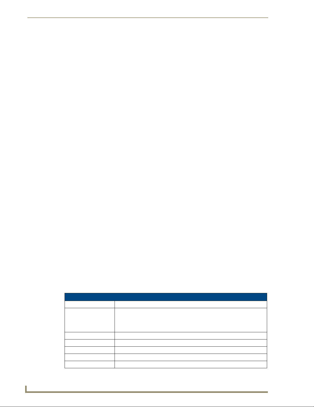
Setup Pages
Information Button
The Information button allows access of both the Project Information page, which contains data on the
TPDesign4 file being used with the MVP-5200i, and the Panel Information page, which contains
detailed information on the panel itself. To access these pages:
1. Press and hold the Information button until the Project Information button and the Panel
Information button slide from the left.
The Project Information and the Panel Information buttons will be displayed for
three seconds before they slide back behind the Information button, whether or not
the Information button is still being pressed.
2. Press the appropriate button for the information required.
3. To return to the Setup page, press the Back button.
Project Information Page
The Project Information page displays the project properties of the TPDesign4 project file currently
loaded on the panel (FIG. 51).
54
FIG. 51 Project Information page
Features on this page include:
Project Information Page
Back: Saves all changes and returns to the previous page.
Connection Status icon: The icon in the upper-right corner of each Setup page provides a constant visual
indication of current connection status.
Note: a Lock appears on the icon if the panel is connected to a secured NetLinx
Master.
File Name: Displays the name of the TPDesign4 project file downloaded to the panel.
Designer ID: Displays the designer information.
File Revision: Displays the revision number of the file.
Dealer ID: Displays the dealer ID number (unique to every dealer and entered in TPD4).
Job Name: Displays the job name.
MVP-5200i Modero Viewpoint Widescreen Touch Panel
Page 63

Setup Pages
Project Information Page (Cont.)
Sales Order: Displays the sales order information.
Purchase Order: Displays the purchase order information.
AMX IR 38K Assigned
Port:
AMX IR 455K Assigned
Port:
IR User Def1 Port: Displays the primary channel port used by the IR receiver on the panel.
IR User Def2 Port: Displays the secondary channel port used by the IR receiver on the panel
Build Number: Displays the build number information of the TPD4 software used to create the
Creation Date: Displays the project creation date.
Revision Date: Displays the last revision date for the project.
Last Save Date: Displays the last date the project was saved.
Blink Rate: Displays the feedback blink rate, in 10-second increments.
Job Comments: Displays any comments associated to the job (from the TPD4 project file).
Cradle Sensor Port: Displays the port used by the charging cradle sensor.
Cradle Sensor Channel: Displays the channel used to broadcast the charging cradle sensor status.
Displays the AMX 38 kHz IR channel port used by the IR Emitter on the panel.
• This information is specified in TPD4 (Project Properties > IR Emitters &
Receivers tab).
• For example, if you set the AMX IR 38K Port to 7 and then put a button on the
panel with a channel code of 5 and a port of 7, it will trigger the IR code in slot 5
of the AMX IR 38K Port.
Displays the AMX 455 kHz IR channel port used by the IR Emitter on the panel.
project file.
IR receivers and transmitters on G4 panels share the device address number of the
panel.
MVP-5200i Modero Viewpoint Widescreen Touch Panel
55
Page 64

Setup Pages
Panel Information Page
The Panel Information page provides detailed panel information (FIG. 52).
FIG. 52 Panel Information page
Features on this page include:
Panel Information Page
Back: Saves all changes and returns to the previous page.
Connection Status icon: The icon in the upper-right corner of each Setup page provides a constant
visual indication of current connection status.
Note: a Lock appears on the icon if the panel is connected to a secured NetLinx
Master.
Panel Type: Displays the model of the panel being used.
Firmware Version: Displays the version number of the G4 firmware loaded on the panel.
Setup Port: Displays the setup port information (value) being used by the panel.
High Port: Displays the high port (port count) value for the panel.
High Address: Displays the high address (address count) value for the panel.
High Channel: Displays the high channel (channel count) value for the panel.
High Level: Displays the high level (level count) value being used by the panel.
Serial Number: Displays the specific serial number value assigned to the panel.
Setup Pages Version: Displays the type and version of the Setup pages being used by the panel.
Screen Width: Displays the screen width (in pixels). MVP-5200i = 640 pixels.
Screen Height: Displays the screen height (in pixels). MVP-5200i = 480 pixels.
Screen Refresh Rate: Displays the video refresh rate applied to the incoming video signal.
Screen Rotation: Displays the degree of rotation applied to the on-screen image.
Power Up Page: Displays the page assigned to display after the panel is powered-up.
Start Up String: Displays the start-up string.
Wake Up String: Displays the wake up string used after an activation from a timeout.
Sleep String: Displays the sleep string used during a panel’s sleep mode.
File System: Displays the amount of Compact Flash memory available on the panel.
RAM: Displays the available RAM (or Extended Memory module) on the panel.
Panel Start Time: Displays the time taken by the panel to wake up from sleep mode.
Bulb Hours: Displays the number of hours elapsed with the display on full power.
56
MVP-5200i Modero Viewpoint Widescreen Touch Panel
Page 65

Setup Pages
Time & Date Settings Page
The options on the Time & Date Settings page (FIG. 53) allows setting and adjusting of time and date
information on the NetLinx Master. If the time and/or date on the Master is modified, all connected
devices will be updated to reflect the new information.
FIG. 53 Time and Date Setup page
The MVP-5200i does not have an on-board clock, so the only way to modify a panel’s
time without altering the Master is via NetLinx Code.
Features on this page include:
Time & Date Setup Page
Back: Saves all changes and returns to the previous page.
Connection Status icon: The icon in the upper-right corner of each Setup page provides a constant visual
indication of current connection status.
Note: a Lock appears on the icon if the panel is connected to a secured NetLinx
Master.
Time Date Refresh/Set: • The Get Time button retrieves Time and Date information from the Master.
• The Set Time button retains and saves any time/date modifications made on the
panel.
Time Display fields: • These fields display the time in three formats: STANDARD, STANDARD AM/PM,
and 24 HOUR.
Date Display fields: • These fields display the calendar date information in several different formats.
Set Date/Time: Use the Up/Down arrow buttons to adjust the Master’s calendar date and time. The
blue icon indicates which field is currently selected.
• Year range = 2000 - 2199
• Month range = 1 - 12
• Day range = 1 - 31
• Hour = 24-hour military
• Minute range = 0 - 59
• Second range = 0 - 59
MVP-5200i Modero Viewpoint Widescreen Touch Panel
57
Page 66

Setup Pages
Audio Settings Page
The Audio Settings page allows adjustment of volume levels and panel sounds settings (FIG. 54).
FIG. 54 Audio Settings pages
Features on these pages include:
Audio Settings Page
Back: Saves all changes and returns to the previous page.
Connection Status icon: The icon in the upper-right corner of each Setup page provides a constant
Master Volume: This section allows you to alter the current master volume level:
Default Panel Sounds: • Activating the Button Hit button plays a default sound when you touch an
Internal Sound Level: Adjusts the volume level on the panel’s internal speaker:
visual indication of current connection status.
Note: a Lock appears on the icon if the panel is connected to a secured NetLinx
Master.
• Use the Up/Down buttons to adjust the volume level in 25-percent increments
(range = 0 - 100).
• The Master Volume bargraph indicates the current volume level. Press the
bargraph to the left or right of the graph marker to adjust the volume level in
one-percent increments (range = 0 - 100), or press the bargraph and hold to
move the graph marker to the desired level.
• The Mute button toggles the Mute feature.
active button.
• Activating the Button Miss button plays a default sound when you touch a
non-active button or any area outside of the active button
•The Play Test Sound button plays a test WAV/MP3 file over the panel’s
internal speakers.
• Use the Up/Down buttons to adjust the volume (range = 0 - 100)
• The Internal Sound Level bargraph indicates the current sound level. Press
the bargraph to the left or right of the graph marker to adjust the volume level
in one-percent increments (range = 0 - 100), or press the bargraph and hold
to move the graph marker to the desired level.
• The Mute button mutes the internal speaker volume
58
MVP-5200i Modero Viewpoint Widescreen Touch Panel
Page 67

Audio Settings Page (Cont.)
Analog
Line In Level: Adjusts the volume level of any analog signal coming into the device:
• Use the Up/Down buttons to adjust the input level (range = 0 - 100)
• The Line In Level bargraph indicates the current input level. Press the
bargraph to the left or right of the graph marker to adjust the volume level in
one-percent increments (range 0 - 100), or press the bargraph and hold to
move the graph marker to the desired level.
• The Mute button mutes the line input.
Intercom
Mic Level: Adjusts the volume level on the intercom’s microphone:
• Use the Up/Down buttons to adjust the microphone level (range = 0 - 100).
Press the bargraph to the left or right of the graph marker to adjust the
volume level in one-percent increments (range 0 - 100), or press the
bargraph and hold to move the graph marker to the desired level.
Intercom Volume: Sets the volume level for intercom calls from another MVP-5200i:
• Use the Up/Down buttons to adjust the Line-In volume level (range = 0 - 100).
• The Line-In Level bargraph indicates the current Line-In level. Press the
bargraph to the left or right of the graph marker to adjust the volume level in
one-percent increments (range 0 - 100), or press the bargraph and hold to
move the graph marker to the desired level.
• The Mute button mutes the Line-In volume.
Audio Output
Audio Output: Enables USB headphone output.
Setup Pages
WAV files - Supported sample rates
The following sample rates for WAV files are supported by MVP-5200i panels:
Supported WAV Sample Rates
• 48000 Hz • 16000 Hz
• 44100 Hz • 12000 Hz
• 32000 Hz • 11025 Hz
• 24000 Hz • 8000 Hz
• 22050 Hz
MVP-5200i Modero Viewpoint Widescreen Touch Panel
59
Page 68

Setup Pages
Battery Settings Page
The options on the Battery Settings page allow setting of power warning preferences and battery status
information, and adjustment of the display times for battery warnings (FIG. 55).
FIG. 55 Battery page
Features on this page include:
Battery Page
Back: Saves all changes and returns to the previous page.
Connection Status icon: The icon in the upper-right corner of each Setup page provides a constant
visual indication of current connection status.
Note: a Lock appears on the icon if the panel is connected to a secured NetLinx
Master.
Low Battery Warning: The Up/Down buttons adjust the time value (in minutes) available on the battery
Panel Shutdown: This value determines the number of minutes that would need to pass before
Battery Charge Status: The Battery Charge Status field indicates the power charge currently available
Battery Level Port: The Battery Level Port field indicates the port being used to report charge
Battery Level: The Battery Level field indicates the level being used to report status levels
Battery Power Brightness
Limit:
(for use) before the panel displays a low battery warning. Range - 10 - 45,
default = 15 min.
the panel automatically shuts down. Once shut down, the device would have to
be restarted. The Up/Down buttons alter the timeout value (in minutes). A value
of 0 disables this feature.
Range = 0 - 240, default = 0.
on the battery.
status levels back to the NetLinx Master (set in TPDesign4).
back to the NetLinx Master (set in TPDesign4).
The DISABLE/DISABLED button acts as a power save feature with two options:
• Disable - Clicking on this button deactivates this power save feature. The
panel will use the Panel Brightness level.
• Disabled - Clicking on this button activates the brightness limit set on the
panel, conserving battery power. Activating this feature causes the panel to
function at 80% of full brightness and overrides the Panel Brightness value
set on the Setup page.
60
MVP-5200i Modero Viewpoint Widescreen Touch Panel
Page 69

Protected Setup Pages
The Protected Setup page (FIG. 56) provides secured access to advanced panel configuration options,
including communication and security settings. The Protected Setup page is accessed through the Setup
page (please refer to the Setup Pages section on page 51).
To access the Protected Setup pages:
1. Press the center button of the navigation wheel and hold for 3 to 5 seconds to access the Setup
pages.
2. Select the Protected Setup button on the left side of the screen.
3. Enter the factory default password (1988) into the password keypad to access the page.
Protected Setup Pages
FIG. 56 Protected Setup page showing default values
Features on the Protected Setup page include:
Protected Setup Page
Navigation Buttons: The buttons along on the left side of the page provide access to secondary
Protected Setup pages (see following sections).
Back: Saves all changes and returns to the previous page.
Connection Status icon: The icon in the upper-right corner of each Protected Setup page provides a
Device Number: Opens a keypad used to view or change the device number of the panel.
Options: • Function Show - toggles the display of the channel port, channel code, level
constant visual indication of current connection status.
Note: a Lock appears on the icon if the panel is connected to a secured NetLinx
Master.
port and level code on all touch panel buttons (see FIG. 57).
• Tel net - enables or disables the panel’s telnet server, allowing or preventing
direct telnet communication to the panel.
• Page Tracking - toggles the page tracking function. When enabled, the panel
reports page data to the NetLinx Master.
• Front Button Setup Access - activates the navigation wheel for accessing
the Setup and Calibration pages (see FIG. 56 on page 61). The default
setting is On.
MVP-5200i Modero Viewpoint Widescreen Touch Panel
61
Page 70

Protected Setup Pages
Protected Setup Page (Cont.)
System Recovery: • Reset System Settings - Deletes all of the current configuration parameters
Reboot/Shutdown Panel: • Pressing the Reboot button causes the panel to reboot after saving any
Docking Station • Dock Status - Illuminates when the panel is docked and communicating with
Channel Code
on the panel (including IP Addresses, Device Number assignments,
Passwords, and other presets). This option invokes a Confirmation dialog,
prompting you to confirm your selection before resetting the panel.
• Remove User Pages - Removes all TPD4 touch panel pages currently on the
panel, including the pre-installed AMX Demo pages. This option invokes a
Confirmation dialog, prompting you to confirm your selection before removing
the panel pages.
Note that the YES button on the Confirmation dialog is disabled for 5 seconds
as additional protection against accidentally resetting the panel or removing
the panel pages.
changes.
• Pressing the Shutdown button causes the panel to shut down after saving
any changes.
the Charging Station.
• Undock Panel - Releases panel from Wall Mounted Charging Station.
Channel Port
0.20
BUTTON
0,8 0,50
Level Port
Channel Code
FIG. 57 Function Show example
Address Port
Address Code
When the Function Show feature is displayed, the Channel Port and Code will appear
in yellow, the Address Port and Code in green, and the Level Port and Channel Code
in purple.
To reboot the panel:
1. Access the Protected Setup page.
2. Press the Reboot button.
3. Wait until the panel completes its reboot.
4. Log back into the Protected Setup page, if necessary.
To shut down the panel:
1. Access the Protected Setup page.
2. Press the Shutdown button.
3. Disconnect any power source plugs or USB connections, if necessary.
62
MVP-5200i Modero Viewpoint Widescreen Touch Panel
Page 71

Protected Setup Pages
Protected Setup Navigation Buttons
The Protected Setup Navigation Buttons (FIG. 58) appear on the left edge of the Protected Setup page.
Press to access the System Settings page, which contains IP Settings and Master
Connection information.
Press to access the Wireless Settings page, which allows configuration of wireless
connection settings.
Press to access the Calibration page, which allows proper calibration of the panel.
Press to access the G4 Web Control page, which enables and disables remote
display and control of the panel via a web-enabled PC running a VNC client.
Press to access the Passwords Setup page, to specify firmware
and user access passwords.
Press to access the Tools page, for panel connection logs, panel statistics,
and the Connection Utility.
FIG. 58 Protected Setup Navigation Buttons
MVP-5200i Modero Viewpoint Widescreen Touch Panel
63
Page 72

Protected Setup Pages
System Settings Page
The System Settings page (FIG. 59) displays sets the NetLinx Master’s communication settings.
FIG. 59 System Settings page
The elements of this page include:
System Settings Page Elements
Back: Saves all changes and returns to the previous page.
Connection Status icon: The icon in the upper-right corner of each Protected Setup page provides a
IP Settings: Switches the IP settings between DHCP and Static . DHCP means that the IP
Master Connection: Sets the NetLinx Master communication values:
constant visual indication of current connection status.
Note: a Lock appears on the icon if the panel is connected to a secured NetLinx
Master.
address and the subnet mask fields are greyed out; in Static, press either of the
fields to open the IP Address and Subnet Mask keypads.
Type Sets the NetLinx Master to communicate with the panel via Ethernet, USB,
Mesh, or ICSNet. This is based on the cable connection from the rear.
• Ethernet is a CAT-5 cable (10/100Base T terminated in an RJ-45 connector)
used to network computers together and is used in most LAN (local area
networks). This description is also used to refer to both wired and wireless
communication. A Wireless Ethernet connection involves indirect
communication from the panel to a Master via a wireless connection to the
network.
•A USB connection is a direct connection from the panel’s mini-USB port to a
corresponding USB port on the PC (acting as a Virtual Master).
64
MVP-5200i Modero Viewpoint Widescreen Touch Panel
Page 73

Protected Setup Pages
System Setting Page Elements (Cont.)
Mode Cycles between the connection modes: URL, Listen, NDP(UDP,) URL(UDP),
System Number Allows entry of a system number. Default value is 0 (zero).
Master IP/URL Sets the Master IP or URL of the NetLinx Master.
Master Port Number Allows entry of the port number used with the NetLinx Master. Default = 1319
Username/Password If the target Master has been previously secured, enter the alpha-numeric string
NDP Name Displays the name of the device connecting to the Master.
and Auto.
(Ethernet Only - disabled when USB is selected)
• URL - In this mode, enter the IP/URL, Master Port Number, and username/
password (if used) on the Master. The System Number field is read-only - the
panel obtains this information from the Master.
• Listen - In this mode, add the panel address into the URL List in NetLinx
Studio and set the connection mode to Listen. This mode allows the Modero
touch panel to “listen” for the Master’s communication signals. The System
Number and Master IP/URL fields are read-only.
• NDP(UDP) - In this mode, The System Number and Master IP/URL fields are
read-only.
• URL(UDP) - In this mode, The System Number and Master IP/URL fields are
read-only.
• Auto - In this mode, enter the System Number and a username/password (if
applicable). Use this mode when both the panel and the NetLinx Master are
on the same Subnet and the Master has its UDP feature enabled. The Master
IP/URL field is read-only.
(ETHERNET in Auto Mode Only - disabled when USB is selected)
(ETHERNET in URL and URL(UDP) Modes Only - disabled when USB is
selected)
(ETHERNET Only - disabled when USB is selected)
(into each field) assigned to a pre-configured user profile on the Master. This
profile should have the pre-defined level of access/configuration rights.
Refer to the Step 3: Choose a Master Connection Mode section on page 35 for more detailed information
on using the System Settings page.
MVP-5200i Modero Viewpoint Widescreen Touch Panel
65
Page 74

Protected Setup Pages
Wireless Settings Page
Use the options on the Wireless Settings page (FIG. 60) to configure communication settings for the
wireless CF card (802.11b/g), and read the device number assigned to the panel.
FIG. 60 Wireless Settings page (reads from and assigns values to the WAP)
Features on this page include:
Wireless Settings Page
Back: Saves all changes and returns to the previous page.
Connection Status icon: The icon in the upper-right corner of each Protected Setup page provides a
constant visual indication of current connection status.
Note: a Lock appears on the icon if the panel is connected to a secured NetLinx
Master.
IP Settings: Sets the IP communication values for the panel:
DHCP/STATIC Sets the panel to either DHCP or Static communication modes.
• DHCP - a temporary IP Addresses is assigned to the panel by a DHCP
server. If DHCP is selected, the other IP Settings fields are disabled (see
below).
• Static IP is a permanent IP Address assigned to the panel. If Static IP is
selected, the other IP Settings fields are enabled (see below).
IP Address Enter the secondary IP address for this panel.
Subnet Mask Enter the subnetwork address for this panel.
Gateway Enter the gateway address for this panel.
Host Name Enter the host name for this panel.
Primary DNS Enter the address of the primary DNS server used by this panel for host name
lookups.
Secondary DNS Enter the secondary DNS address for this panel.
Domain Enter a unique name to the panel for DNS look-up.
MAC Address This unique address identifies the wireless Ethernet card in the panel (read-
Active Roaming on
Channels 1&11
only).
When enabled, connection allows active roaming between WAPs by switching
between channels 1 and 11 if the other channel is unavailable.
66
MVP-5200i Modero Viewpoint Widescreen Touch Panel
Page 75

Protected Setup Pages
Wireless Settings Page (Cont.)
Access Point MAC
Address:
Wireless Security: Sets the wireless security method to be used by the panel to connect to the
Open (Clear Text) This button opens the Open (Clear Text) Settings page (FIG. 62 on page 70).
Static WEP This button opens the Static WEP Settings page (FIG. 63 on page 71).
WPA-PSK This button opens the WPA-PSK Settings page (FIG. 64 on page 73).
EAP-PEAP This button opens the EAP-PEAP Settings page (FIG. 69 on page 79).
EAP-TTLS This button opens the EAP-TTLS Settings page (FIG. 70 on page 81).
This unique address identifies the Wireless Access Point (WAP) used by this
panel for wireless communication (read-only).
• Site Survey button: Launches the Wireless Site Survey page. The options on
this page allow you to detect (“sniff-out”) all WAPs transmitting within range of
the panel’s Wi-Fi card.
Data displayed on the Site Survey page is categorized by:
- Network Name (SSID) - WAP names
- Channel (RF) - channels currently being used by the WAP
- Security Type - security protocol enabled on the WAP, if detectable
- Signal Strength - None, Poor, Fair, Good, Very Good, and Excellent
- MAC Address - Unique identification of the transmitting Access Point
• Refer to the Using the Site Survey tool section on page 27 for more detailed
information on the SIte Survey page.
• When communicating with a NXA- WAP200G, enter the MAC Address
(BSSID) of the target WAP as the Access Point MAC Address. Refer to the
WAP200G Instruction Manual for more information.
network. Selecting any of the connection method buttons invokes the relevant
configuration page, with options that allow you to define parameters specific to
the selected method of connection.
“Open” security does not utilize any encryption methodology, but requires an
SSID (alpha-numeric) entry. This entry must match the Network Name (SSID)
entry of the target WAP so the panel knows what device it is using to
communicate with the network.
• Refer to the Open (Clear Text) Settings section on page 70 for further details.
“Static WEP” security requires that both a target WAP be identified and an
encryption method be implemented prior to establishing communication.
• Refer to the Static WEP Settings section on page 71 for further details.
“WPA-PSK” security is designed for environments where is it desirable to use
WPA or WPA2, but an 802.1x authentication server is not available.
PSK connections are more secure than WEP and are simpler to configure,
since they implement dynamic keys but share a key between the WAP and the
panel (client).
• Refer to the WPA-PSK Settings section on page 73 for further details.
“EAP-PEAP” security is designed for wireless environments where it is necessary to securely transmit data over a wireless network.
• Refer to the EAP-PEAP Settings section on page 79 for further details.
• For information on uploading a certificate file, refer to the AMX Certificate
Upload Utility section on page 173.
“EAP-TTLS” security is designed for wireless environments where having a
Radius server directly validate the identity of the client (panel) is necessary
before allowing it access to the network.
• Refer to the EAP-TTLS Settings
• For information on uploading a certificate file, refer to the AMX Certificate
Upload Utility section on page 173.
section on page 81 for further details.
MVP-5200i Modero Viewpoint Widescreen Touch Panel
67
Page 76

Protected Setup Pages
Wireless Settings Page (Cont.)
Wireless Security (Cont.):
RF Link Info: These options set communication values for the wireless interface card:
EAP-TLS This button opens the EAP-TLS Settings page (FIG. 71 on page 83).
“EAP-TLS” security is designed for wireless environments where securely
transmitting data over a wireless network by adding an additional level of
security protocol is necessary via the use of a private key.
• Refer to the EAP-TLS Settings section on page 83 for further details.
• For information on uploading a certificate file, refer to the AMX Certificate
Upload Utility section on page 173.
EAP-LEAP This button opens the EAP-LEAP Settings page (FIG. 66 on page 75).
“EAP-LEAP” security is designed for wireless environments where it is not
required to have both a client or server certificate validation scheme in place,
yet necessary to securely transmit data over a wireless network.
• Refer to the EAP-LEAP Settings section on page 75.
EAP-FAST This button opens the EAP-FAST Settings page (FIG. 68 on page 77).
“EAP-FAST” security is designed for wireless environments where security and
ease of setup are equally desirable.
• Refer to the EAP-FAST Settings section on page 77 for further details.
SSID Displays the currently used SSID of the target WAP.
Channel The RF channel being used for connection to the WAP (read -only).
Link Quality Displays the quality of the link from the wireless NIC to the Wireless Access
Point (direct sequence spread spectrum) in real time (None, Poor, Fair, Good,
Very Good, and Excellent).
• Even when link quality is at its lowest you still have a connection, and the
ability to transmit and receive data, even if at lower speeds.
Note: “Link Quality” and “Signal Strength” are applicable to RF connections
only. It is possible to have an RF signal to a WAP, but be unable to communicate with it because of either incorrect IP or encryption settings.
Signal Strength This indicator displays a description of the signal strength from the Wireless
Access Point connection in real time (None, Poor, Fair, Good, Very Good, and
Excellent).
SNR (Signal Noise Ratio) is a measure of the relative strength of a wireless RF
connection. Given this value and the link quality above, you can determine the
noise level component of the SNR. For example, if signal strength is high but
the link quality is low, then the cause of the link degradation is noise. However,
if signal strength is low and link quality is low the cause would simply be signal
strength.
68
MVP-5200i Modero Viewpoint Widescreen Touch Panel
Page 77
Protected Setup Pages
Wireless Security
The options on the Wireless Security section (FIG. 61) include the wireless security methods supported
by the NXA-WC80211GCF Wi-Fi card. These security methods incorporate WPA, WPA2, and EAP
technology, some of which require the upload of unique certificate files to a target panel. Refer to the
Appendix B: Wireless Technology section on page 166 for further information.
Some encryption and security features may or may not be supported:
Wireless Security Support
802.11g Wi-Fi CF card: • Open (Clear Text)
• Static WEP (64-bit and 128-bit key lengths)
• WPA-PSK
• EAP security (with and without certificates)
• WAP SIte Survey
Refer to the Configuring Wireless Network Access section on page 25 for more information on
configuring the panel for wireless network access using the various security options.
FIG. 61 Wireless Security section
MVP-5200i Modero Viewpoint Widescreen Touch Panel
69
Page 78

Protected Setup Pages
Open (Clear Text) Settings
Press the Open (Clear Text) button to open the Open (Clear Text) Settings page (FIG. 62).
FIG. 62 Wireless Settings page - Open (Clear Text) Settings
Open security does not utilize any encryption methodology, but requires an SSID (alpha-numeric) entry.
This entry must match the Network Name (SSID) entry of the target WAP so the panel knows what
device it is using to communicate with the network.
Open (Clear Text) Settings
SSID (Service Set Identifier): Opens an on-screen keyboard to enter the SSID name used on the target
WAP. The SSID is a unique name used by the WAP, and is assigned to all
panels on that network. An SSID is required by the WAP before the panel is
permitted to join the network.
• The SSID is case sensitive and must not exceed 32 characters.
• Make sure this setting is the same for all points in your wireless network.
• NXA-WAP200Gs use AMX as their default SSID.
• If this field is left blank, the panel will attempt to connect to the first available
WAP.
Save/Cancel: • Save - store the new security information, apply changes, and return to the
previous page.
• Cancel - discard changes and return to the previous page.
Refer to the Configuring Wireless Network Access section on page 25 and the Using the Site Survey
tool section on page 27 for further details on these security options.
70
MVP-5200i Modero Viewpoint Widescreen Touch Panel
Page 79

Static WEP Settings
Press the Static WEP button to open the Static WEP Settings page (FIG. 63).
FIG. 63 Wireless Settings page - Static WEP Settings
Protected Setup Pages
Static WEP security requires that both a target WAP be identified and an encryption method be
implemented prior to establishing communication. In addition to providing both Open and Shared
Authentication capabilities, this page also supports Hexadecimal and ASCII keys.
Static WEP Settings
SSID (Service Set Identifier): Opens an on-screen keyboard to enter the SSID name used on the target
WEP 64 / WEP 128: Cycles through the available encryption options: 64 or 128 Bit Key Size.
WAP. The SSID is a unique name used by the WAP, and is assigned to all
panels on that network. An SSID is required by the WAP before the panel is
permitted to join the network.
• The SSID is case sensitive and must not exceed 32 characters.
• Make sure this setting is the same for all points in your wireless network.
• NXA-WAP200Gs use AMX as their default SSID.
• If this field is left blank, the panel will attempt to connect to the first available
WAP.
“WEP” (Wired Equivalent Privacy) is an 802.11 security protocol designed to
provide wireless security equivalent to wired networks.
• WEP64 enables WEP encryption using a 64 Bit Key Size. All packets are
transmitted with their contents encrypted using the Default WEP Key.
• WEP128 enables WEP encryption using a 128 Bit Key Size. All packets are
transmitted with their contents encrypted using the Default WEP Key.
• If the key is not the correct size, the system will resize it to match the
number of bits required for the WEP encryption mode selected.
MVP-5200i Modero Viewpoint Widescreen Touch Panel
71
Page 80

Protected Setup Pages
Static WEP Settings (Cont.)
Generate (Passphrase): This button displays an on-screen keyboard which allows you to enter a
Default Key: Cycles through the four available WEP key identifiers to select a WEP key to
WEP Keys: This feature provides another level of security by selecting up to four WEP
Current Key: Displays the current WEP key in use.
Authentication: Toggles between the two authentication modes: Open (broadcast publicly) or
Save/Cancel: • Save - store the new security information, apply changes, and return to the
passphrase. The panel then automatically generates four WEP keys that are
compatible only with Modero panels. Enter these WEP keys into the target
WAP.
When working with multiple panels, WEP Keys must be entered into the WAP
for each panel.
• All Modero panels use the same code key generator. Therefore, this
Passphrase generates identical keys on any Modero panel.
• The Passphrase generator is case sensitive.
Note: This Key generator is unique to Modero panels and does not generate
the same keys as non-AMX wireless devices. For example, a Current Key
string generated anywhere else will not match those created on Modero
panels.
use. As the Default Key value is altered (through selection) the corresponding
“Current Key” is displayed. Each Current Key corresponds to a WEP key.
This feature is useful for accessing different networks without having to
re-enter that networks’ WEP key. It is also sometimes used to set up a
rotating key schedule to provide an extra layer of security.
Keys.
Push any of the four buttons to open an on-screen keyboard. Both ASCII and
HEX keys are supported. Up to four keys can be configured for both.
• An ASCII key utilizes either 5 or 13 ASCII characters
• A HEX key utilizes either 10 or 26 Hexidecimal characters
Press Done to accept any changes and save the new value.
Note: A 64-bit key will be 10 characters in length while a 128-bit key will be
26 characters in length. The length of the key entered determines the level of
WEP encryption employed (64 or 128-bit). 128-bit keys may be used if
supported by the internal wireless card.
• When working with a single panel and a single WAP, manually entering the
Current Key from the WAP into the selected WEP Key is recommended.
• When working with a single WAP and multiple panels, generating a Current
Key using the same passphrase on all panels and then entering the
panel-produced WEP key manually into the Wireless Access Point is
recommended.
• Keys may also be examined by touching the key buttons and noting the
keyboard initialization text.
• Use the on-screen keyboard’s Clear button to erase stored key information.
Shared (encrypted).
•An Open network allows connections from any client without authentication.
•A Shared network requires the client to submit a key which is shared by the
network WAP before it is given permission to associate with the network. In
this case the key is the same as the WEP encryption key.
In either case, if WEP encryption has been enabled, the client will still require
the WEP key to encrypt and decrypt packets in order to communicate with the
network.
previous page.
• Cancel - discard changes and return to the previous page.
72
Refer to the Configuring Wireless Network Access section on page 25 and the Using the Site Survey
tool section on page 27 for further details on these security options.
MVP-5200i Modero Viewpoint Widescreen Touch Panel
Page 81

Protected Setup Pages
WPA-PSK Settings
Press the WPA-PSK button to opens the WPA-PSK dialog (FIG. 64).
FIG. 64 Wireless Settings page - WPA-PSK Settings
WPA-PSK security is designed for environments where using WPA or WPA2 is desirable, but an 802.1x
authentication server is not available. PSK connections are more secure than WEP and are simpler to
configure, since they implement dynamic keys but share a key between the WAP and the panel (client).
Using WPA-PSK, the encryption on the WAP could either be WPA or WPA2. The firmware in the panel
will automatically connect to the WAP using the correct encryption. The WPA encryption type is
configured on the WAP, not in the firmware.
WAPs do not display “WPA” or “WPA2” on their configuration screens:
WPA is normally displayed as TKIP.
WPA2 is normally displayed as AES CCMP.
The following fields are required: SSID and Password/Pass Phrase.
Enter the SSID of the WAP.
Enter a pass phrase with a minimum of 8 characters and a maximum of 63.
The exact same pass phrase (including capitalization) must be entered in the access point.
WPA-PSK Settings
SSID (Service Set Identifier): Opens an on-screen keyboard to enter the SSID name used on the target
WAP. The SSID is a unique name used by the WAP, and is assigned to all
panels on that network. An SSID is required by the WAP before the panel is
permitted to join the network.
• The SSID is case sensitive and must not exceed 32 characters.
• Make sure this setting is the same for all points in your wireless network.
• NXA-WAP200Gs use AMX as their default SSID.
• If this field is left blank, the panel will attempt to connect to the first available
Password/Pass Phrase: Opens an on-screen keyboard to enter a passphrase (password).
• This alpha-numeric string must use a minimum of 8 characters and a
• The exact pass phrase string (including capitalization) must be entered on
MVP-5200i Modero Viewpoint Widescreen Touch Panel
WAP.
maximum of 63.
the target WAP.
73
Page 82

Protected Setup Pages
WPA-PSK Settings (Cont.)
Save/Cancel: • Save - store the new security information, apply changes, and return to the
EAP Security & Server Certificates - Overview
The following EAP types all support a server certificate:
All three of these certificate-using security methods are documented in the following sections. EAP
Authentication goes a step beyond simply encrypting data transfers, but also requires that a set of
credentials be validated before the client (panel) is allowed to connect to the rest of the network
(FIG. 65). Please note that no user intervention is necessary during this process, as it proceeds
automatically based on the configuration parameters entered into the panel.
previous page.
• Cancel - discard changes and return to the previous page.
Refer to the Configuring Wireless Network Access section on page 25 for details on these
security options.
Refer to the Using the Site Survey tool section on page 27 for more information on using this
tool.
EAP-PEAP
EAP-TTLS
EAP-TLS
LAN
802.1x
(EAP over Wireless)
Client - Panel
(supplicant)
FIG. 65 EAP security method in process
Authenticator
(Wireless Access Point)
Authentication Server
(RADIUS Server)
A server certificate file uses a certificate installed in a panel so that the RADIUS server can be validated
before the panel tries to connect to it. The field name associated with this file is Certificate Authority.
If a server certificate is used, it should first be downloaded into the panel and the Certificate Authority
field should then be set to the name of that certificate file. No file path should be used for this setting, as
all certificates are stored in a specific directory that the user cannot control or change. The most secure
connection method uses a server certificate.
If no server certificate will be used, this field should be left blank. If the field contains a file name, then a
valid certificate file with the same file name must be previously installed on the panel. Otherwise the
authentication process will fail.
74
MVP-5200i Modero Viewpoint Widescreen Touch Panel
Page 83

EAP-LEAP Settings
Press the EAP-LEAP button to open the EAP-LEAP Settings page (FIG. 66).
Protected Setup Pages
FIG. 66 Wireless Settings page - EAP-LEAP Settings
EAP (Extensible Authentication Protocol) is an Enterprise authentication protocol that can be used in
both wired and wireless network environments. EAP requires the use of an 802.1x Authentication
Server, also known as a Radius server. The configuration fields described below take variable length
strings as inputs. An on-screen keyboard is opened when these fields are selected.
LEAP (Lightweight Extensible Authentication Protocol) was developed to transmit authentication
information securely in a wireless network environment.
LEAP does not use client (panel) or server (RADIUS) certificates, and is therefore
one of the least secure EAP security methods. However, it can be utilized
successfully by implementing sufficiently complex passwords.
EAP-LEAP security is designed for wireless environments where having a client or server certificate
validation scheme in place is not required, yet necessary to transmit data securely over a wireless
network.
MVP-5200i Modero Viewpoint Widescreen Touch Panel
75
Page 84

Protected Setup Pages
EAP-LEAP Settings
SSID (Service Set Identifier): Opens an on-screen keyboard to enter the SSID name used on the target
Identity: Opens an on-screen keyboard. Enter an EAP Identity string (used by the
Password: Opens an on-screen keyboard. Enter the network password string specified
Save/Cancel: • Save - store the new security information, apply changes, and return to the
WAP.
The SSID is a unique name used by the WAP, and is assigned to all panels
on that network. An SSID is required by the WAP before the panel is
permitted to join the network.
• The SSID is case sensitive and must not exceed 32 characters.
• Make sure this setting is the same for all points in the wireless network.
• NXA-WAP200Gs use AMX as their default SSID.
• With EAP security, the SSID of the WAP must be entered. If it is left blank,
the panel will try to connect to the first access point detected that supports
EAP. However, a successful connection is not guaranteed because the
detected WAP may be connected to a RADIUS server, which may not
support this EAP type and/or have the proper user identities configured.
panel to identify itself to an Authentication (RADIUS) Server).
Note: This information is similar to a username used to login to a secured
server or workstation. This works in tandem with the Password string which is
similar to the password entered to gain access to a secured workstation.
Typically, this is in the form of a username such as jdoe@amx.com.
for the user entered within the Identity field (used by the panel to identify itself
to an Authentication (RADIUS) Server)
Note: This information is similar to the password entered to gain access to a
secured workstation.
previous page.
• Cancel - discard changes and return to the previous page.
Refer to the EAP Authentication section on page 170 for further details on these security
options.
Refer to FIG. 67 for an example of how a typical EAP-LEAP system configuration page
should appear.
76
FIG. 67 EAP-LEAP sample Cisco System Security page
MVP-5200i Modero Viewpoint Widescreen Touch Panel
Page 85

EAP-FAST Settings
Press the EAP-FAST button to open the EAP-FAST Settings dialog (FIG. 68).
FIG. 68 Wireless Settings page - EAP-FAST Settings
Protected Setup Pages
EAP-FAST (Flexible Authentication via Secure Tunneling) security was designed for wireless
environments where security and ease of setup are equally desirable. EAP-FAST uses a certificate file,
however it can be configured to download the certificate automatically the first time the panel attempts to
authenticate itself. Automatic certificate downloading is convenient but slightly less secure, since its the
certificate is transferred wirelessly and could theoretically be “sniffed-out”.
EAP-FAST Settings
SSID (Service Set Identifier): Opens an on-screen keyboard to enter the SSID name used on the target
Identity: Opens an on-screen keyboard to enter an EAP Identity string (used by the
WAP.
The SSID is a unique name used by the WAP, and is assigned to all panels
on that network. An SSID is required by the WAP before the panel is
permitted to join the network.
• The SSID is case sensitive and must not exceed 32 characters.
• Make sure this setting is the same for all points in the wireless network.
• NXA-WAP200Gs use AMX as their default SSID.
• With EAP security, the SSID of the WAP must be entered. If it is left blank,
the panel will try to connect to the first access point detected that supports
EAP. However, a successful connection is not guaranteed because the
detected WAP may be connected to a RADIUS server, which may not
support this EAP type and/or have the proper user identities configured.
panel to identify itself to an Authentication (RADIUS) Server).
Note: This information is similar to a username used to login to a secured
server or workstation. This works in tandem with the Password string which is
similar to the password entered to gain access to a secured workstation.
Typically, this is in the form of a username such as: jdoe@amx.com.
MVP-5200i Modero Viewpoint Widescreen Touch Panel
77
Page 86

Protected Setup Pages
EAP-FAST Settings (Cont.)
Anonymous Identity: Opens an on-screen keyboard to enter an IT provided alphanumeric string
Password: Opens an on-screen keyboard. Enter the network password string specified
Automatic PAC
Provisioning:
PAC File Location: This field is used when the previous Automatic PAC Provisioning option has
Save/Cancel: • Save - store the new security information, apply changes, and return to the
which (similar to the username) is used as the identity, but that does not
represent a real user.
This information is used as a fictitious name which might be seen by sniffer
programs during the initial connection and setup process between the panel
and the Radius server. In this way the real identity (username) is protected.
Typically, this is in the form of a fictitious username, such as
anonymous@amx.com
for the user entered within the Identity field (used by the panel to identify itself
to an Authentication (RADIUS) Server)
Note: This information is similar to the password entered to gain access to a
secured workstation.
This selection toggles PAC (Protected Access Credential) Provisioning Enabled (automatic) or Disabled (manual).
• If Enabled is selected, the following PAC File Location field is disabled,
because the search for the PAC file is done automatically.
• If Disabled is selected, the user is required to manually locate a file
containing the PAC shared secret credentials for use in authentication. In
this case, the IT department must create a PAC file and then transfer it into
the panel using the AMX Certificate Upload application.
Note: Even when automatic provisioning is enabled, the PAC certificate is
only downloaded the first time that the panel connects to the RADIUS server.
This file is then saved into the panel's file system and is then reused from
then on. It is possible for the user to change a setting, such as a new Identity,
that would invalidate this certificate. In that case, the panel must be forced to
download a new PAC file. To do this, set Automatic PAC Provisioning to
Disabled and then back to Enabled. This forces the firmware to delete the old
file and request a new one.
been Disabled.
• When pressed, the panel displays an on-screen PAC File Location
keyboard which allows you to enter the name of the file containing the PAC
shared secret credentials for use in authentication.
• This field is only valid when the automatic PAC provisioning feature has
been enabled via the previous field.
previous page.
• Cancel - discard changes and return to the previous page.
78
Refer to the EAP Authentication section on page 170 and the Using the Site Survey tool section on
page 27 for further details on these security options.
MVP-5200i Modero Viewpoint Widescreen Touch Panel
Page 87

EAP-PEAP Settings
Press the EAP-PEAP button to open the EAP-PEAP Settings page (FIG. 69).
FIG. 69 Wireless Settings page - EAP-PEAP Settings
Protected Setup Pages
PEAP (Protected Extensible Authentication Protocol) was developed as a way to securely transmit
authentication information, such as passwords, over a wireless network environment. PEAP uses only
server-side public key certificates and therefore does not need a client (panel) certificate which makes
the configuration and setup easier.
There are two main versions of the PEAP protocol supported by panel’s DeviceScape Wireless Client:
PEAPv0
PEAPv1
PEAP uses inner authentication mechanisms supported by the DeviceScape Wireless Client, the most
common of which are:
MSCHAPv2 with PEAPv0
GTC with PEAPv1
MVP-5200i Modero Viewpoint Widescreen Touch Panel
79
Page 88

Protected Setup Pages
EAP-PEAP security is designed for wireless environments where it is necessary to transmit data securely
over a wireless network.
EAP-PEAP Settings
SSID (Service Set Identifier): Opens an on-screen keyboard to enter the SSID name used on the target
Identity: Opens an on-screen keyboard to enter an EAP Identity string (used by the
Password: Opens an on-screen keyboard to enter the network password string specified
Certificate Authority: When pressed, the panel displays an on-screen Certificate Authority (CA)
PEAP Version: When pressed, this field cycles through the choices of available PEAP:
Inner Authentication Type: When pressed, this field cycles through the choices of available Inner
Save/Cancel: • Save - store the new security information, apply changes, and return to the
WAP. The SSID is a unique name used by the WAP, and is assigned to all
panels on that network. An SSID is required by the WAP before the panel is
permitted to join the network.
• The SSID is case sensitive and must not exceed 32 characters.
• Make sure this setting is the same for all points in the wireless network.
• NXA-WAP200Gs use AMX as their default SSID.
• With EAP security, the SSID of the WAP must be entered. If it is left blank,
the panel will try to connect to the first access point detected that supports
EAP. However, a successful connection is not guaranteed because the
detected WAP may be connected to a RADIUS server, which may not
support this EAP type and/or have the proper user identities configured.
panel to identify itself to an Authentication (RADIUS) Server).
Note: This information is similar to a username used to login to a secured
server or workstation. This works in tandem with the Password string, which
is similar to the password entered to gain access to a secured workstation.
Typically, this is in the form of a username such as jdoe@amx.com.
for the user entered within the Identity field (used by the panel to identify itself
to an Authentication (RADIUS) Server)
Note: This information is similar to the password entered to gain access to a
secured workstation.
File Location keyboard, which allows you to enter the name of the certificate
authority file which is used to validate the server certificate.This field is
optional.
If a server certificate is used, it should first be downloaded into the panel and
the Certificate Authority field should then be set to the name of that certificate
file. No file path should be used for this setting as all certificates are stored in
a specific directory that the user cannot control or change.
Use the on-screen keyboard’s Clear button to erase completely any
previously stored network path information.
PEAPv0, PEAPv1, or PEAPv1 w/peaplabel=1.
Authentication mechanisms supported by the Devicescape Secure Wireless
Client. The most commonly used are: MSCHAPv2 and GTC.
• MSCHAPv2 (used with PEAPv0)
•GTC (used with PEAPv1)
•OTP
•MD5
previous page.
• Cancel - discard changes and return to the previous page.
80
Refer to the EAP Authentication section on page 170 and the Using the Site Survey tool section on
page 27 for further details on these security options.
MVP-5200i Modero Viewpoint Widescreen Touch Panel
Page 89

EAP-TTLS Settings
Press the EAP-TTLS button to opens the EAP-TTLS Settings page (FIG. 70).
Protected Setup Pages
FIG. 70 Wireless Settings page - EAP-TTLS Settings
TTLS (EAP Tunneled Transport Layer Security) is an authentication method that does not use a client
certificate to authenticate the panel. However. this method is more secure than PEAP because it does not
broadcast the identity of the user. Setup is similar to PEAP, but differs in the following areas:
An anonymous identity must be specified until the secure tunnel between the panel and the
Radius server is setup to transfer the real identity of the user.
There is no end-user ability to select from the different types of PEAP.
Additional Inner Authentication choices are available to the end-user.
EAP-TTLS security is designed for wireless environments where the Radius server needs to validate
directly the identity of the client (panel) before allowing it access to the network. This validation is done
by tunneling a connection through the WAP and directly between the panel and the Radius server. Once
the client is identified and then validated, the Radius server disconnects the tunnel and allows the panel
to access the network directly via the target WAP.
EAP-TTLS Settings
SSID (Service Set Identifier): Opens an on-screen keyboard to enter the SSID name used on the target
WAP.
The SSID is a unique name used by the WAP, and is assigned to all panels
on that network. An SSID is required by the WAP before the panel is
permitted to join the network.
• The SSID is case sensitive and must not exceed 32 characters.
• Make sure this setting is the same for all points in the wireless network.
• NXA-WAP200Gs use AMX as their default SSID.
• With EAP security, the SSID of the WAP must be entered. If it is left blank,
the panel will try to connect to the first access point detected that supports
EAP. However, a successful connection is not guaranteed because the
detected WAP may be connected to a RADIUS server, which may not
support this EAP type and/or have the proper user identities configured.
MVP-5200i Modero Viewpoint Widescreen Touch Panel
81
Page 90

Protected Setup Pages
EAP-TTLS Settings (Cont.)
Identity: Opens an on-screen keyboard. Enter an EAP Identity string (used by the
Anonymous Identity: Opens an on-screen keyboard. Enter an IT provided alpha-numeric string
Password: Opens an on-screen keyboard. Enter the network password string specified
Certificate Authority: When pressed, the panel displays an on-screen Certificate Authority (CA)
Inner Authentication Type: When pressed, this field cycles through the choices of available Inner
Save/Cancel: • Save - store the new security information, apply changes, and return to the
panel to identify itself to an Authentication (RADIUS) Server).
Note: This information is similar to a username used to login to a secured
server or workstation. This works in tandem with the Password string which is
similar to the password entered to gain access to a secured workstation.
Typically, this is in the form of a username such as: jdoe@amx.com.
which (similar to the username) used as the identity, but that does not
represent a real user.
This information is used as a fictitious name which might be seen by sniffer
programs during the initial connection and setup process between the panel
and the Radius server. In this way the real identity (username) is protected.
Typically, this is in the form of a fictitious username such as:
anonymous@amx.com
for the user entered within the Identity field (used by the panel to identify itself
to an Authentication (RADIUS) Server)
Note: This information is similar to the password entered to gain access to a
secured workstation.
File Location keyboard which allows you to enter the name of the certificate
authority file which is used to validate the server certificate. This field is
optional.
If a server certificate is used, it should first be downloaded into the panel and
the Certificate Authority field should then be set to the name of that certificate
file. No file path should be used for this setting as all certificates are stored in
a specific directory that the user cannot control or change.
Use the on-screen keyboard’s Clear button to completely erase any
previously stored network path information.
Authentication mechanism supported by the Devicescape Secure Wireless
Client:
• EAP-MSCHAPv2
• EAP-GTC
• EAP-OTP
• EAP-MD5
• MSCHAPv2
• MSCHAP
•PAP
• CHAP
previous page.
• Cancel - discard changes and return to the previous page.
82
Refer to the EAP Authentication section on page 170 and the Using the Site Survey tool section on
page 27 for further details on these security options.
MVP-5200i Modero Viewpoint Widescreen Touch Panel
Page 91

EAP-TLS Settings
Press the EAP-TLS button to open the EAP-TLS Settings page (FIG. 71).
Protected Setup Pages
FIG. 71 Wireless Settings page - EAP-TLS Settings
TLS (Transport Layer Security) was the original standard wireless LAN EAP authentication protocol.
TLS requires additional work during the deployment phase, but provides additional security since even a
compromised password is not enough to break into an EAP-TLS protected wireless network
environment.
EAP-TLS security is designed for wireless environments where it is necessary to securely transmit data
over a wireless network by adding an additional level of security protocol via the use of a private key.
EAP-TLS Settings
SSID (Service Set Identifier): Opens an on-screen keyboard for entering the SSID name used on the target
WAP. The SSID is a unique name used by the WAP, and is assigned to all
panels on that network. An SSID is required by the WAP before the panel is
permitted to join the network.
• The SSID is case sensitive and must not exceed 32 characters.
• Make sure this setting is the same for all points in the wireless network.
• NXA-WAP200Gs use AMX as their default SSID.
• With EAP security, the SSID of the WAP must be entered. If it is left blank,
the panel will try to connect to the first access point detected that supports
EAP. However, a successful connection is not guaranteed because the
detected WAP may be connected to a RADIUS server, which may not
support this EAP type and/or have the proper user identities configured.
Identity: Opens an on-screen keyboard for entering an EAP Identity string (used by
the panel to identify itself to an Authentication (RADIUS) Server).
Note: This information is similar to a username used to login to a secured
server or workstation. This works in tandem with the Password string, which
is similar to the password entered to gain access to a secured workstation.
Typically, this is in the form of a username such as: jdoe@amx.com.
MVP-5200i Modero Viewpoint Widescreen Touch Panel
83
Page 92

Protected Setup Pages
EAP-TLS Settings (Cont.)
Certificate Authority: When pressed, the panel displays an on-screen Certificate Authority (CA)
Client Certificate: Opens an on-screen keyboard for entering the name of the file containing the
Private Key: When pressed, the panel displays an on-screen Client Private Key File
Private Key password: This field should only be used if the Private Key is protected with a password.
Save/Cancel: • Save - store the new security information, apply changes, and return to the
File Location keyboard, for entering the name of the certificate authority file
which is used to validate the server certificate.
This field is optional.
If a server certificate is used, it should first be downloaded into the panel and
the Certificate Authority field should then be set to the name of that certificate
file. No file path should be used for this setting, as all certificates are stored in
a specific directory that the user cannot control or change.
• Use the on-screen keyboard’s Clear button to completely erase any
previously stored network path information.
client (panel) certificate for use in certifying the identity of the client (panel).
• Refer to the Client certificate configuration section on page 85 for
information regarding Client Certificates and their parameters.
Location keyboard for entering the name of the file containing the private key.
• Use the on-screen keyboard’s Clear button to completely erase any
previously stored network path information.
If no password protection is associated with the Private Key, then this field
should be left blank.
• When pressed, the panel displays an on-screen Private Key Password
keyboard which allows you to enter an alpha-numeric password string.
• Use the on-screen keyboard’s Clear button to completely erase any
previously stored network path information.
previous page.
• Cancel - discard changes and return to the previous page.
Refer to the EAP Authentication section on page 170 for further details on these security
options.
Refer to the Using the Site Survey tool section on page 27 for more information on using this
feature.
84
MVP-5200i Modero Viewpoint Widescreen Touch Panel
Page 93
Protected Setup Pages
Client certificate configuration
A client certificate can be configured by an IT department in several ways. The client certificate and
private key can both be incorporated into one file or split into two separate files. In addition, the file
format used by these files could be PEM, DER, or PKCS12. These formats are described later in this
section. The following table describes how to fill in the fields for each possible case.
Client Certificate Configuration
Certificate Configuration Client Certificate Field Private Key Field
Single file contains both the client certificate and
the private key. Format is: PEM or DER.
First file contains the client certificate, second file
contains the private key. Format is: PEM or DER.
Single file contains both the client certificate and
the private key. Format is: PKCS12
First file contains the client certificate, second file
contains the private key. Format is: PKCS12
AMX supports the following security certificates
PEM (Privacy Enhanced Mail)
DER (Distinguished Encoding Rules)
PKCS12 (Public Key Cryptography Standard #12)
Enter the file name Enter the same file name
Enter the first file name Enter the second file name
Leave this field blank Enter the file name
Not supported Not supported
PKCS12 files are frequently generated by Microsoft certificate applications.
Otherwise, PEM is more common.
Certificate files frequently use 5 file extensions. It can be confusing because there is not a one to one
correspondence. The following table shows the possible file extension used for each certificate type:
Certificates and their Extensions
Certificate Type Possible File Extensions
PEM .cer
.pem
.pvk
DER .cer
.der
PKCS12 .pfx
Please note which certificate types are supported by the different certificate fields used on the
configuration screens (PEAP, TTLS, and TLS). The following table outlines the firmware fields and their
supported certificate types.
Certificate Types Supported by the Modero Firmware
Configuration Field Name Certificate File Type Supported
Certificate Authority field PEM and DER
Client Certificate field PEM and DER
Private Key field .PEM, DER, and PKCS12
MVP-5200i Modero Viewpoint Widescreen Touch Panel
85
Page 94

Protected Setup Pages
Calibration Page
The Calibration page (FIG. 72) allows you to calibrate the touch panel for accurate button selection.
FIG. 72 Calibration page
1. Press and hold the center button on the navigation wheel for 6 seconds to access the Calibration
page (see FIG. 56).
2. Press the crosshairs in turn. If the crosshairs are not touched within ten seconds, the MVP-5200i
will return to the Protected Setup page.
3. The page will read "Calibration Successful. Touch to continue." Touch anywhere on the screen to
return to the Protected Setup page.
If the screen is not touched at that point, the device will automatically return to the
Protected Setup page within 10 seconds.
Always calibrate the panel before its initial use, and after downloading new firmware.
86
MVP-5200i Modero Viewpoint Widescreen Touch Panel
Page 95

Protected Setup Pages
G4 Web Control Settings Page
An on-board VNC (Virtual Network Computing) server allows the panel to connect to any remote PC
running a VNC client. Once connected, the client can view and control the panel remotely. The options
on this page allow you to enable/disable G4 Web Control functionality(FIG. 73).
FIG. 73 G4 Web Control page
Features on this page include:
G4 Web Control Page
Back: Saves all changes and returns to the previous page.
Connection Status icon: The icon in the upper-right corner of each Protected Setup page provides a
constant visual indication of current connection status.
Note: a Lock appears on the icon if the panel is connected to a secured NetLinx
Master.
G4 Web Control Settings: Sets the IP communication values for the touch panel:
Enable/Enabled The Enable/Enabled button toggles between the two G4 activation settings:
• Enable - deactivates G4 Web Control on the panel.
• Enabled - activates G4 Web Control on the panel.
Network Interface Select Toggles between the two network interface options:
• Wireless - the panel is communicating via a Wireless Access Point (WAP).
• Wired - the panel is communicating via its mini-USB port.
Web Control Name Use this field to enter a unique alpha-numeric string to be used as the panel’s
display name within the Manage WebControl Connections window of the
NetLinx Security browser window.
Web Control Password Use this field to enter the G4 Authentication session password required for
Web Control Port Use this field to enter the number of the port used by the VNC Web Server.
Maximum Number of
Connections
Current Connection Count Displays the number of users currently connected to this panel via VNC.
G4 Web Control Timeout: Sets the length of time (in minutes) that the panel can remain idle, detecting no
VNC access to the panel.
Default = 5900.
Displays the maximum number of users that can be simultaneously connected
to this panel via VNC. Default = 1.
cursor movements, before the G4 Web Control session is terminated.
• Minimum value = 0 minutes (panel never times out)
• Maximum value = 240 minutes (panel times out after 240 minutes)
MVP-5200i Modero Viewpoint Widescreen Touch Panel
87
Page 96

Protected Setup Pages
Refer to the Using G4 Web Control to Interact with a G4 Panel section on page 45 for
instructions on using the G4 Web Control page with the web-based NetLinx Security
application.
88
MVP-5200i Modero Viewpoint Widescreen Touch Panel
Page 97

Protected Setup Pages
Other Settings
Press the Other Settings button to display the two settings options for Cache and Password. Press one
of the options within three seconds, or the two options buttons will slide back behind the Other Settings
button.
Cache Settings Page
The options on the Cache Settings page (FIG. 74) allow setting and clearing of the flash memory cache,
as well as viewing the status of the current cache settings. Since image files take up a significant amount
of the MVP-5200i’s flash memory, being able to examine the current limits and contents is useful in
deciding whether to increase or decrease the total flash cache size.
FIG. 74 Cache Settings Page
Cache Settings Page
Back: Saves all changes and returns to the previous page.
Connection Status icon: The icon in the upper-right corner of each Protected Setup page provides a
constant visual indication of current connection status.
Note: a Lock appears on the icon if the panel is connected to a secured NetLinx
Master.
Image Cache Settings
Flash Cache Size: Use the Up/Down buttons to increase or decrease the total size of the flash
Cache Expires: Use the Up/Down buttons to control the amount of time elapsed before the
Enable: Saves any changes made to the Flash Cache Size or Cache Expires fields.
Clear Cache: Clears all files previously stored in the flash memory cache.
Image Cache Status
RAM Max Size: The maximum size allocated to the RAM cache.
RAM Current Size: The size of the current RAM cache contents.
RAM Hit Rate: The number of times the RAM cache was referenced since the last cache
Items In Cache (RAM): The total number of cached images in the RAM cache.
Flash Current Size: The maximum size allocated to the flash cache.
Flash Hit Rate: The number of times the flash cache was referenced since the last cache
Items in Cache (Flash): The total number of cached images in the flash cache.
memory cache, up to a maximum of 171MB.
panel automatically deletes its cache, with increments of 2 hours, 8 hours, 1
day, 2 days, 5 days, and "NEVER".
clearing.
clearing.
MVP-5200i Modero Viewpoint Widescreen Touch Panel
89
Page 98

Protected Setup Pages
Password Settings Page
The options on the Password Settings page (FIG. 75) allow assignment of passwords required for users
to access the Protected Setup page, and to release the device from a MVP-WCS-52 Charging Station.
FIG. 75 Password Setup page
Features on this page include:
Password Setup Page
Back: Saves all changes and returns to the previous page.
Connection Status icon: The icon in the upper-right corner of each Protected Setup page provides a
In Panel Password
Change:
User Access: Lists all previous password users, in the order in which they accessed the
Enable/Enabled: When enabled, this button notes that all password entry attempts will be
Report: When enabled, this button sends a report to the Master on any attempts or
constant visual indication of current connection status.
Note: a Lock appears on the icon if the panel is connected to a secured NetLinx
Master.
Accesses the alphanumeric values associated to particular password sets.
• The PASSWORD 1, 2, 3, 4 and 5 (protected) buttons open a keyboard to
enter alphanumeric values associated to the selected password group.
Note: Clearing Password #5 removes the need to enter a password before
accessing the Protected Setup page.
device.
recorded.
successes at entering a password.
To change a previously established password:
1. In the Password Settings page, press the button in the In Panel Password Change section for the
particular password to be changed.
90
Password 5 is protected, and can only be changed by the Administrator.
2. In the Pass word keyboard, enter the new alphanumeric password.
3. Press Done when complete.
MVP-5200i Modero Viewpoint Widescreen Touch Panel
Page 99

Protected Setup Pages
The User Access section allows the Administrator to control access of all individuals using or attempting
to use the MVP-5200i. From this section, new users may be given access rights to the device; however,
they will NOT be given access to the Protected Settings page.
Only one of the main passwords may be used to access the Protected Settings page.
An individual user password may not be used to access the Protected Settings page
unless it matches one of the main passwords.
To list a new user within the User Access section:
1. Press a blank button in the User Access section.
2. In the Name keyboard, enter the user’s name or nickname and press Done when finished.
3. In the Passw ord keyboard, enter the selected alphanumeric password and press Done when finished.
4. The new user’s name will appear in the left column of User Access section. The password will also
appear in the right column, but its characters will be replaced with asterisks.
No matter how many characters are in an actual password, the Password column in
the User Access section will always show five asterisks.
To change a User Access password:
1. Press the button corresponding to the user’s name in the User Access section.
2. In the Pass word keyboard, enter the user’s password and press Done.
3. Press the password button in the right column of the User Access section.
4. Enter the new password into the Passw ord keyboard and press Done.
To view all previous instances of users accessing the device:
1. From the Password Settings page, press the Enable button to highlight it. The MVP-5200i will
record all successful and unsuccessful attempts to access the touch panel.
2. Press the Record button to send a record to the network Master of all recorded attempts to access
the device. This record may be retrieved from the Master at any time.
MVP-5200i Modero Viewpoint Widescreen Touch Panel
91
Page 100

Protected Setup Pages
Tools
Press and hold the Tools button to access the MVP-5200i’s Panel Logs, Panel Statistics, and
Connection Utility buttons (FIG. 76). Each of these buttons opens a separate page, covered in detail
below.
FIG. 76 Tools button menu
The Tools button menu will remain visible for three seconds, regardless of whether
or not the button continues to be held.
Panel Connection Logs Page
The Panel Connection Logs page (FIG. 77) chronicles all previous connections between the device and
the network.
92
FIG. 77 Panel Connection Logs Page
Panel Connection Logs Page
Back: Saves all changes and returns to the previous page.
Connection Status icon: The icon in the upper-right corner of each Protected Setup page provides a
constant visual indication of current connection status.
Note: a Lock appears on the icon if the panel is connected to a secured NetLinx
Master.
Clear: Clears all connection logs.
Refresh: Refreshes displayed log information.
Page: Displays the current log page number. Use the Up/Down arrows to select log
pages.
MVP-5200i Modero Viewpoint Widescreen Touch Panel
 Loading...