

Page 1
QUICK START GUIDE
MT-2002 20.3” Modero G5 Panoramic Tabletop Touch Panel
Overview
The MT-2002 20.3” Modero G5 Panoramic Tabletop Touch Panel
(FG5969-35) features the G5 Graphics Engine to provide fast and smooth
animations and transitions, as well as a Quad Core Processor.
The MT-2002 features a panoramic capacitive multi-touch screen that
provides users access to multiple applications with minimal navigation. The
distinctive, low-prole design is engineered to sit perfectly on a table without
obstructing views.
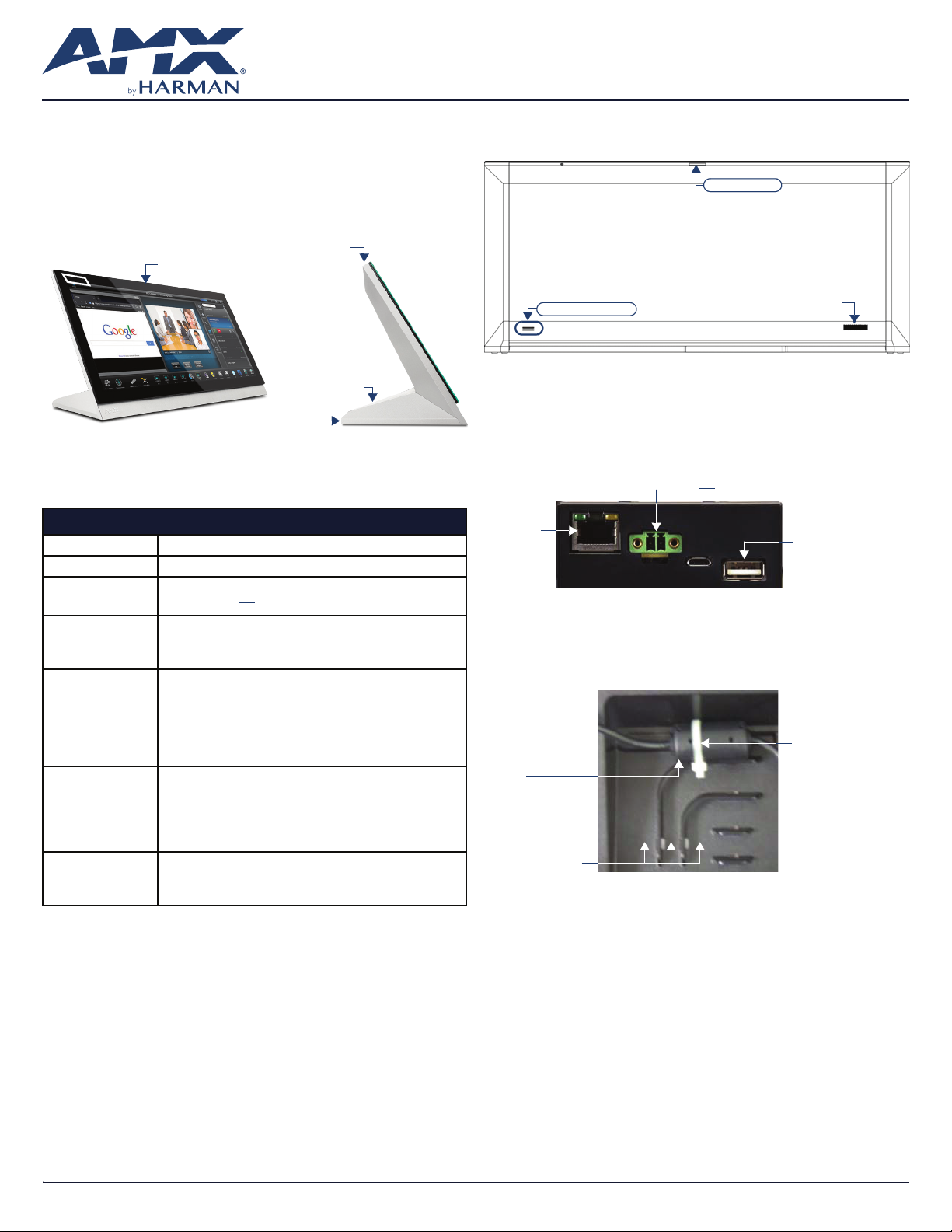
Sleep button
Sleep button
USB Ports (2)
Cable slot
FIG. 1 MT-2002
Product Specifications
MT-2002 SPECIFICATIONS
Dimensions (HWD) 9 3/16” x 20 3/8” x 5 7/8” (235 mm x 519 mm x 150 mm)
Weight 12.3 lbs (5.58 Kg)
Power
Consumption
External Power
Supply Required
Certications • FCC Part 15 Class B
Environmental • Temperature (Operating): 32°F to 104°F (0°C to 40°C)
Included
Accessories
Full-On: 35 W (12V
Standby: 7 W (12V
Requires one of these AMX power sources (not included):
• PSR5.4 Power Supply, 12 VDC, 5.4A, 3.5mm Phoenix Connector with
Retention Screws (FG423-48)
• MXA-MPL Modero X/S Series Multi Preview Live (FG5968-10)
• C-Tick CISPR 22 Class B
• CE EN 55022 Class B and EN 55024
• CB Scheme IEC 60950-1
• IC
• IEC/EN-60950
• UL 60950-1
• RoHS/WEEE compliant
• Temperature (Storage): 4°F to 140°F (-20°C to 60°C)
• Humidity (Operating): 20% to 85% RH
• Humidity (Storage): 5% to 85% RH
• Power (“Heat”) Dissipation:
On: 119.4 BTU/hr
Standby: 23.9 BTU/hr
• Locking 2-pin Phoenix connector (41-0002-SA)
• MXA-USB-C, USB Port Cover Kit (FG5968-18)
• HPG-10-10K, 3/4” Mini-Grommet (FG570-01)
• MXA-CLK, Modero X/S Series Cleaning Kit (FG5968-16)
..., 2.6A)
..., 0.52A)
Connector Locations
Two Type A USB ports are located on the rear right corner of the device (FIG. 2).
Sleep button
Type A USB Ports
FIG. 2 MT-2002-REAR VIEW
USB peripherals (mouse, keyboard, etc.) may be connected to either of the two
USB ports on the rear of the device.
The power and Ethernet connectors, as well as an additional USB port are
located on the bottom of the device (FIG. 3).
The underside USB port, as well as the two rear USB ports, may be used with a
ash drive for page transfers or rmware upgrades.
12V
... Power Port
Ethernet
10/100 Port
FIG. 3 MT-2002 UNDERSIDE CONNECTORS
The MT-2002 does not have individual channels on the base of the device
to allow passage of cables from underneath the base. Instead, it has one slot at
the base to allow options on cable conguration, with channels for securing
power and Ethernet cables (FIG. 4).
Ferrite
Tie-wrap channels
FIG. 4 TIE-WRAP FOR POWER CONNECTOR FERRITE
Each channel side has slots for attaching tie-wraps to secure each cable. The
ferrite on the power cable must be secured with the included tie-wrap during
installation to prevent the possibility of the panel not sitting ush on the table.
Other cables may be secured with tie-wraps if desired, but this is not necessary.
Speaker
Type A USB Port
Tie-wrap
Wiring Guidelines
The MT-2002 uses a 12V ... -compliant power supply to provide power to
the panel via the 2-pin 3.5 mm captive wire PWR connector.
The incoming PWR and GND wires from the power supply must be connected to
the corresponding locations within the PWR connector.
Note: Apply power to the panel only after installation is complete.
Note: Connecting power to the MT-2002 should be done using the included
2-pin 3.5mm captive wire connector included with the device. This connector
is retained within its port with locking screws instead of the pins on each side of
standard captive wire connectors, and using force to insert a standard captive
wire connector may damage the device.
AV FOR AN IT WORLD
®
Page 2
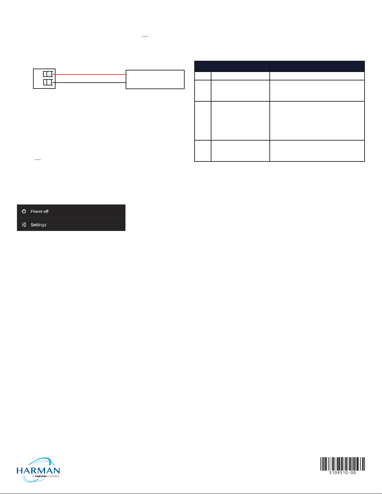
Wiring a Power Connection
To use the 2-pin 3.5 mm captive wire connector with a 12V ... -compliant power
supply, the incoming PWR and GND wires from the external source must be
connected to their corresponding locations on the connector (FIG. 5).
The connector uses locking screws to insure a connection to the device, so
make sure to insert and tighten the screws before applying power.
PWR +
GND -
Power Supply
To the Touch Panel
FIG. 5 NETLINX POWER CONNECTOR WIRING DIAGRAM
1. Insert the PWR and GND wires on the terminal end of the 2-pin 3.5 mm
captive wire cable.
Match the wiring locations of the +/- on both the power supply and the
terminal connector.
2. Tighten the clamp to secure the two wires. Do not tighten the screws
excessively; doing so may strip the threads and damage the connector.
3. Verify the connection of the 2-pin 3.5 mm captive wire to the external
12V
... -compliant power supply and apply power.
Powering On/Off Modero G5 Panels
Modero G5 touch panels may be powered on by touching and holding the
Sleep button. To power off the panel, press and hold the Sleep button, and
select Power Off on the on-screen menu (FIG. 6):
FIG. 6 SLEEP BUTTON - PRESS AND HOLD TO ACCESS POWER OFF/SETTINGS OPTIONS
Configuration and Programming
Modero G5 touch panels are equipped with a Settings menu that provides the
ability to congure various features on the panels. To access the Settings menu,
press and hold the Sleep button, and select Settings.
Note: Information on the Settings menu, panel conguration, and programming
is provided in the Modero G5 Programming Guide, available at www.amx.com.
Connecting to a NetLinx Master
To establish the type of connection to make between the panel and the
NetLinx Master:
1. In the NetLinx page, press Mode to choose the connection mode (URL,
Listen or Auto):
CONNECTION MODES
Mode Description Procedures
URL The device connects to the target
Master’s IP address via a TCP
connection.
Listen This mode allows the panel
to“listen” for the Master’s
communication signals.
Note that in this mode, the System
Number and Master IP/URL elds
are read-only.
Auto Use this mode when both the
panel and the NetLinx Master are
on the same Subnet.
2. If password security is enabled on the target Master, enter the Username
and Password:
a. Select Username to open the NetLinx window.
b. Enter the Username and Password required by the Master.
1. Select URL in the Mode menu.
2. Enter the Master IP/URL, Master Port Number, and
Username/Password (if required by the Master).
3. Press OK to save changes.
1. Select Listen in the Mode menu.
2. Conrm the panel’s IP address is on the Master’s
URL list (via NetLinx Studio).
3. Press OK to save changes.
Note: The Host Name (set on the Ethernet page), can
be used to locate the panel on the Master (particularly
useful for DHCP connections where the IP address
can change).
1. Select Auto in the Mode menu.
2. Enter the System Number and Username and
Password (if applicable).
3. Press OK to save changes.
c. Press OK to save changes and return to the NetLinx page.
Related Software and Additional Documentation
(at www.amx.com)
• Programming the Modero G5 touch panel requires the use of either Rapid
Project Maker (RPM) or the latest version of Netlinx Studio and TPDesign5,
both available to download at www.amx.com. Refer to the NetLinx Studio
and TPDesign5 online help for information.
• For information on designing touch panel pages intended to optimize the
Modero G5 experience, refer to the G5 Considerations Guide.
• For additional information on the MT-2002 panel, refer to the Modero G5
Touch Panel Instruction Manual.
• For detailed information on the Settings menu as well programming
information and instructions on upgrading rmware, refer to the Modero G5
Programming Guide.
• Detailed specications drawings for the MT-2002 are available to download
from www.amx.com.
Setting the Panel’s Device Number and Device Name
1. In the Settings menu, select NetLinx. This opens a password keypad.
2. Enter the panel password into the keypad (the default is 1988) and select
OK to access the NetLinx page.
3. Press Device Number to open the NetLinx editing window.
4. Enter a unique Device Number assignment for the panel and press OK.
5. Enter a unique Device Name assignment for the panel and press OK.
Configuring the Panel’s IP Address
The rst step is to congure the panel’s IP address. Note that this only congures
the panel to communicate with a network; it is still necessary to connect to the
NetLinx Master (see Connecting to a NetLinx Master below).
Network Communication via DHCP
1. In the Ethernet page, press DHCP/Static eld to open the DHCP/Static
window. Note that DHCP is the default setting.
2. Select Host Name, enter the new host name
3. Press OK to save changes.
Network Communication via Static Address
1. In the Ethernet page, press DHCP/Static to open the DHCP/Static window.
2. Select Static to open the Static IP window.
3. Press any eld to open a keypad or keyboard (depending on the eld), and
enter the appropriate network address information.
4. Press OK to save your changes and return to the Ethernet page.
© 2018 Harman. All rights reserved. Modero X and Modero X Series, AMX, AV FOR AN IT WORLD, and HARMAN, and their respective logos are
registered trademarks of HARMAN. Oracle, Java and any other company or brand name referenced may be trademarks/registered trademarks
of their respective companies. AMX does not assume responsibility for errors or omissions. AMX also reserves the right to alter specications
without prior notice at any time. The AMX Warranty and Return Policy and related documents can be viewed/downloaded at www.amx.com.
3000 RESEARCH DRIVE, RICHARDSON, TX 75082 AMX.com | 800.222.0193 | 469.624.8000 | +1.469.624.7400 | fax 469.624.7153
AMX (UK) LTD, AMX by HARMAN - Auster Road, Clifton Moor, York, YO30 4GD United Kingdom • +44 1904-343-100 • www.amx.com/eu/
LAST REVISED: 09/12/2018
 Loading...