

Page 1
QUICK START GUIDE
Last Revised: 3/31/2016
93-2265-26 REV: B
MSD-701-L/2
Touch Panel
RJ-45 Connector
Cable
Replacement RJ-45
Connector Cable
Old RJ-45
Connector Cable
Sleeve
Length
Sleeve
Length
(ECA2265-05)
Touch Panel (bottom)
RJ-45 Connector Cable
Cable Connector
Any Mount Kit
Back Box
Path of
Connector Cable
Wall Surface
Modero S Series Any Mount Kit Replacement Guide
IMPORTANT: READ THIS FIRST!
This guide includes additional instructions for the installation of the MSA-AMK/2-07
and MSA-AMK/2-10 Modero S Series Any Mount Kits. This guide should be read first
before continuing the installation of the Any Mount Kit.
IMPORTANT: You should have already installed the Any Mount Kit back box before
starting this installation. For more information, please refer to the MSA-AMK/2-xx Quick
Start Guide, available from www.amx.com.
Installation
The MSD-701-L/2, MSD-1001-L/2 Modero S Series wall-mount touch panels and
RMBK-701 and RMBK-1001 AMX RoomBook Scheduling Touch Panels use a RJ-45
cable to provide both power and connectivity to the touch panel (FIG. 1).
In some panels, the insulator sleeve on the connector cable may be too long, preventing
proper flexing of the cable and ultimately binding between the touch panel and the Any
Mount Kit back box (FIG. 2).
The MSA-AMK/2-07 and MSA-AMK/2-10 Any Mount Kits come with an alternate RJ-45
connector cable (ECA2265-05), in order to replace the connector cable, if necessary
and facilitate installation of the touch panel into the Any Mount Kit.
MSD-701-L/2 Wall Mount Touch Panel (rear)
FIG. 1
The new RJ-45 connector cable may be recognized bo th by the length of the insulation
sleeve, but also by the tag with the cable’s part number at the end of the sleeve (FIG. 2).
2. Carefully install the cable connector on the new RJ-45 connector cable to the
outlet on the touch panel.
3. Pull suff icient Ethernet cable from the gang box to allow you to connect the
Ethernet cable to the connector cable.
4. Test the incoming wiring by applying power. Verify that the panel is receiving
power and functioning properly to prevent repetition of the installation.
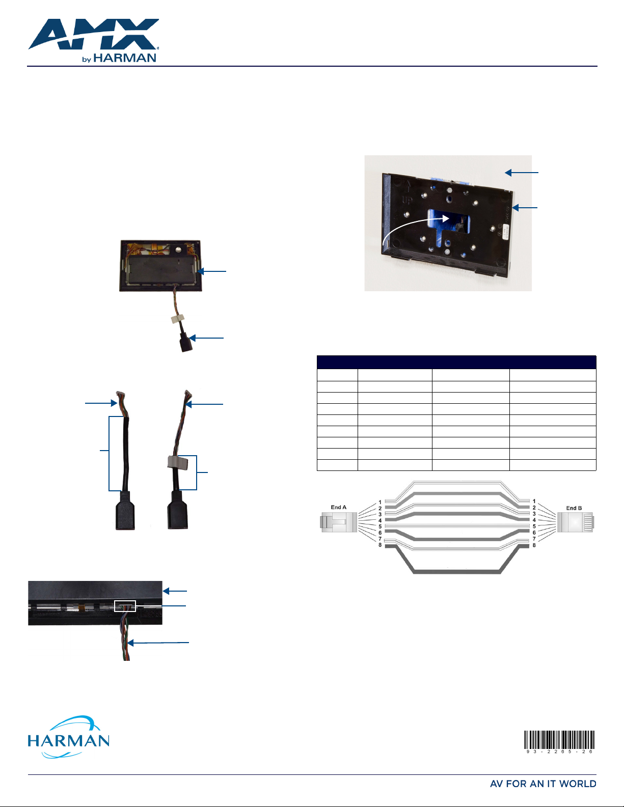
5. Make certain that the path of the RJ-45 connector cable goes straight through the
center hole in the Any Mount Kit back box (FIG. 4). Insure that the connector
cable will not fold up or bind in the slot below the center hole.
FIG. 4 MSA-AMK/2-701 Any Mount Kit back box, path of connector cable
6. Continue with the installation of the touch panel onto the Any Mount Kit back box.
Ethernet/RJ-45 Connections and Wiring
The following table lists the pinouts, signals, and pairing for the Ethernet RJ-45
connector.
Ethernet RJ-45 Pinouts and Signals
Pin Signals Connections Pairing
1 TX + 1 --------- 1 1 --------- 2
2 TX - 2 --------- 2
3 RX + 3 --------- 3 3 --------- 6
4 PoE power 4 --------- 4
5 PoE power 5 --------- 5 4 --------- 5
6 RX - 6 --------- 6
7 PoE power 7 --------- 7 7 --------- 8
8 PoE power 8 --------- 8
FIG. 2 RJ-45 connector cables, old and new
Replacing the RJ-45 Connector Cable
1. From the bottom of the touch panel, gently remove the male cable connector
from its outlet (FIG. 3).
FIG. 3 RJ-45 connector cable inserted into MSD-701-L/2 connector
© 2016 Harman. All rights reserved. Modero, Modero S Series, AMX, AV FOR AN IT WORLD, HARMAN, and their respective logos are registered
trademarks of HARMAN. Oracle, Java and any other company or brand name referenced may be trademarks/registered trademarks of their
respective companies.
AMX does not assume responsibility for errors or omissions. AMX also reserves the right to alter specifications without prior no tice at any time.
The AMX Warranty and Return Policy and related documents can be viewed/downloaded at www.amx.com.
3000 RESEARCH DRIVE, RICHARDSON, TX 75082 AMX.com | 800.222.0193 | 469.624.8000 | +1.469.624.7400 | fax 469.624.7153
AMX (UK) LTD, AMX by HARMAN - Unit C, Auster Road, Clifton Moor, York, YO30 4GD United Kingdom • +44 1904-343-100 • www.amx.com/eu/
RJ-45 wiring diagram
FIG. 5
Additional Documentation
• For information on installing the MSA-AMK/2-07 and MSA-AMK/2-10 Modero S
Series Any Mount Kits, refer to the MSA-AMK/2-xx Quick Start Guide.
• For information on Installing Modero S Series touch panels, refer to the Modero S
Series Instal lation and Hardware Refere nce Guide.
• For information on installing AMX RoomBook Scheduling Panels, refer to the AMX
RoomBook Scheduling Touch Panels Instruction Manual.
 Loading...