

Page 1
Quick Start Guide
Mio R-3 Remote Control Device
Overview
The Mio R-3 remote (FG148-03) provides custom control features, contained in
an elegant handheld rechargeable device. The Mio R-3 communicates with a
NetLinx master via a wireless ZigBee® network.
You need VisualArchitect and KeypadBuilder to properly program this device.
The application and documentation are available from www.amx.com.
1
1
3
2
6957
8
45
10
8
13
16
2
19
11
12
23
25
26
4
11
12
6
9
10
15
14
17
3
7
18
15
21
20
13
16
22
14
24
26
28
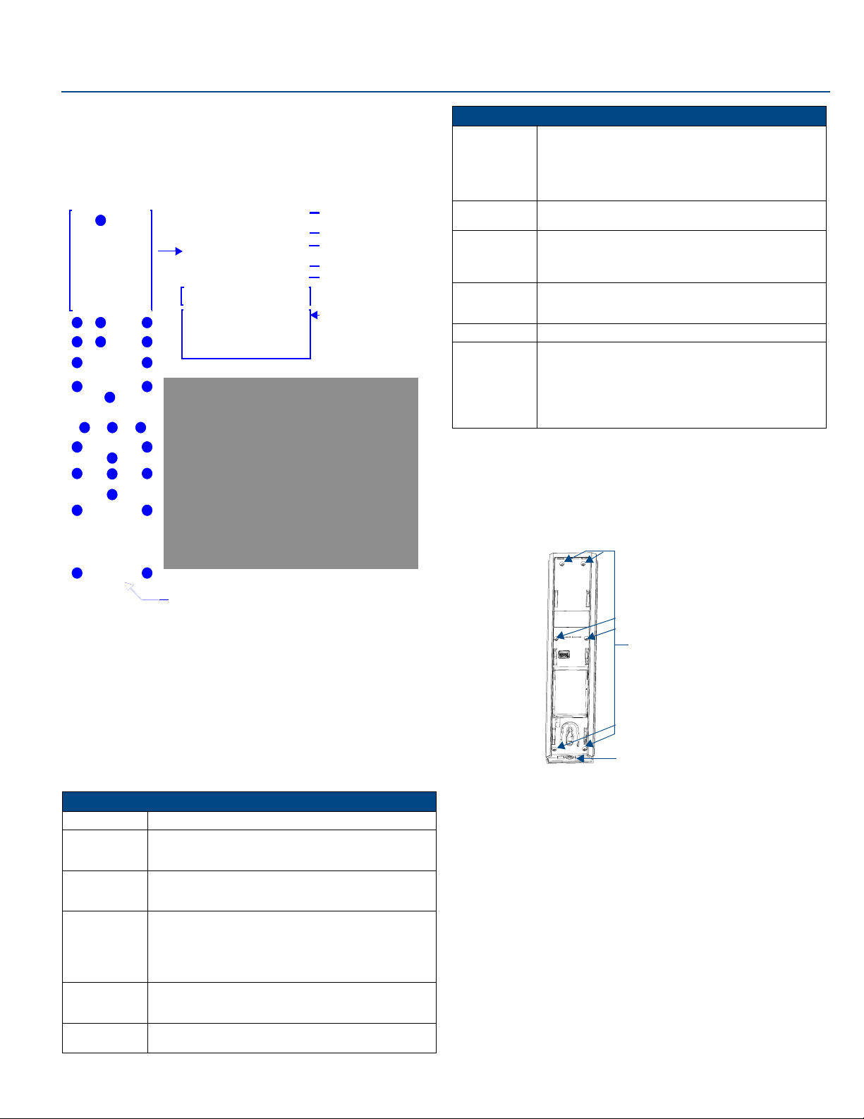
1 - Power
2 - Record
3 - Pause
4 - Stop
5 - Rewind
6 - Play
7 - Fast Forward
8 - Skip Back
9 - Skip Forward
10 - Menu
11 - I nfo
12 - Move Up
13 - Move Left
Numeral Keypad
Power
Transmission Mode
Current Menu
Battery Meter
Custom Macro Buttons
Custom Mode Options
14 - Select
15 - Move Right
16 - Guide
17 - Exit
18 - Move Down
19 - Volume Up
20 - Last Selected
21 - Channel Up
22 - Mute
23 - Volume Down
24 - Channel Down
25 - Input
26 - Enter
Mio R-3 (FG148-03) Specifications (Cont.)
Supported
Languages
Weight • .45 lbs (20 g) without batteries
Certifications • FCC ID: CWU-ZMO
Operating
Environment
Included Items • Mio-RBP Rechargeable Lithium-ion Battery (FG147-10)
Other AMX
Equipment
• English
•French
• German
• Greek
• Italian
• Japanese
• .55 lbs (25 g) with batteries
•CE
• IEC-60950
•TELEC
• Operating Temperature: 0° to 40° C (32° to 104° F)
• Storage Temperature: -20° to 70° C (-4° to 158° F)
• Relative Humidity: 5% to 85%
• DB-9 extension cable (FG10-727)
• Programming Cable - a 3 wire, 2.5 mm stereo jack (FG10-817)
• Custom engraving (FG147-01)
• Mio-RCC Kit (FG147-03K)
• Mio-RCC Charging Base (FG147-02)
•NXR-ZGW (FG5791-01)
•NXR-ZRP (FG5791-02)
• Korean
• Simplified Chinese
• Portuguese
• Russian
• Spanish
• Other languages supported by Glyphs
Installing Your Custom Buttons
1. Flip and turn the Mio R-3 device so that the buttons are facing away from
you and the device is upside down.
2. Holding the device in both hands, place your thumbs on the battery door
and push up to slide the battery door free. The battery door will slide in the
direction of the bottom end of the device.
3. Unscrew the 6 screw points indicated in FIG. 2.
FIG. 1 The Mio R-3 Device
Touch And Tilt Sensor
The Mio R-3 wakes up upon touching either the chrome side rails or pressing a
button. When the remote times out while holding it, you can reawaken the device
by tilting it. Errant jostling such as a bumped table will not wake the device
unless you are holding it.
Specifications
The Mio R-3 device specifications are as follows:
Mio R-3 (FG148-03) Specifications
Battery Rechargeable Lithium-Ion
Transmission
Frequencies
Transmission
Range
Top Components • LED - blue backlit buttons indicate device is awake
Rear Component • Programming Port - 2.5 mm stereo female conductor jack
Dimensions
(HWD)
• Zigbee RF wireless network
• IR 38 Khz
• IR 455 Khz
• ZigBee: 100 feet (30.48m)
• IR 38 Khz: 100 feet (30.48m)
• IR 455 Khz: 50 feet (15.24m)
• Display (OLED) - 128 x 32 pixels, active area is 29.42mm x
7.98mm
• Pushbuttons - the power button is red backlit; the rest are blue
backlit buttons. 45 buttons; 9 custom buttons (3 macro and 6
device).
• Battery Door
• Rechargeable Battery Connection
9.50 x 2.00 x .74 (241.3 mm x 50.8 mm x 18.80 mm)
6 Screw Points
Programming Jack
Internal Mio R-3 Components
FIG. 2
4. Turn the unit over so the buttons are facing you.
5. Lift the top assembly away from the PCB.
6. If necessary, push out the standard buttons from the front of the top assembly.
7. Drop on your custom button pad and verify the alignment with the guide
posts on the PCB.
8. Place the top assembly back down on the PCB and return the unit over,
exposing the 6 screw points.
9. Tighten the 6 screw points.
10. Place the battery door back on the device, and slide the door upwards to
lock it in place.
Page 2
Inserting the Lithium-Ion Battery into The Mio R-3
To install your Lithium-Ion battery into the Mio R-3 remote:
1. Flip and turn the device so that the buttons are facing away from you and
the device is upside down.
2. Holding the device in both hands, place your thumbs on the battery door
and slide the battery door free. The battery door should slide toward the
bottom end of the device.
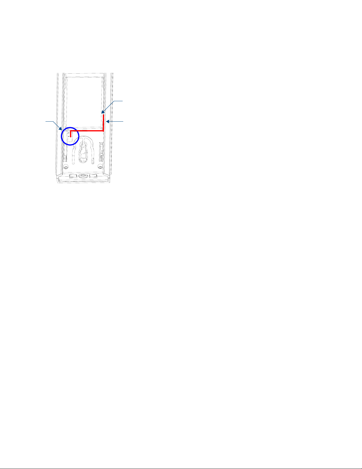
3. Connect the terminal end of the Lithium-Ion battery to the port as shown
in FIG. 3. It may be necessary to use a thin, blunt non-conductive object
to seat the battery connector fully within its port.
Lithium-Ion Battery
Rechargeable
Battery
Port Connection
FIG. 3 Rechargeable Battery Port on The Mio R-3 Remote
Correct path for
battery wires and
connector
Battery Low Indicator
When the battery charge level is too low to sustain continuous operation, the
LCD flashes "Battery Low" and the device shuts down.
Setup Mode
The Setup mode allows you to set the following device features.
Entering
1. Press and hold the STOP button and the INPUT button. The two buttons
2. Press the EXIT key when you are finished.
Note: Your settings will not be lost in the event of battery removal or failure.
Transmit Mode
Press button 1 to select from one of the different available transmit modes. The
transmit mode changes each time 1 is pressed. The predetermined modes are
IR 38 Khz, IR 455 Khz, ZigBee Mode, IR 38 + Zig, and IR 455 + Zig. The
display indicates the selected mode.
Timeout Adjustment
Press button 2 on the remote to change the sleep timeout from the default.
Each time 2 is pressed, the sleep timeout raises incrementally. The predetermined sleep timeouts are 3, 6, 9, and 12 seconds. The display indicates
the selected sleep timeout.
Download Mode
In order to download new firmware or a new configuration or font file to the Mio
R-3 remote using the remote's program port, the remote must first be placed
into Download mode. Press 3 on the remote to toggle the Download mode OFF
and ON. The Download mode must be ON before you can download a file to
the Mio R-3. While the Download mode is ON, the device will not go to sleep.
Once the download is complete, this setting must be returned to Download Off.
A firmware download will cause the remote to reset and this will automatically
reset the remote to Download Off.
Debug Mode
Pressing button 4 on the remote toggles Debug mode between ON and OFF.
Pressing the button toggles to the new mode; 2 seconds after selecting the
mode, the menu returns to Setup mode. The remote will remain in the last
mode selected until Setup mode is once again entered and this mode is
changed by pressing the 4 button.
Setup
mode
must be pressed within 0.1 seconds of each other and held down for 2
seconds. The device indicates you are now in Setup mode. See below for
available modes.
For full warranty information, refer to the AMX Instruction Manual(s) associated with your Product(s).
©2007 AMX. All rights reserved. AMX and the AMX logo are registered trademarks of AMX.
3000 RESEARCH DRIVE, RICHARDSON, TX 75082 • 800.222.0193 • fax 469.624.7153 • technical support 800.932.6993 • www.amx.com
AMX reserves the right to alter specifications without notice at any time.
4/07
Firmware Version
Pressing button 5 on the remote displays the remote and ZigBee firmware
versions currently loaded on the remote. To view the available firmware
versions, press the Move Up arrow on the scroll wheel to scroll up. and
pressing the Move Down arrow will scroll down. When finished, press Exit to
save the changed firmware information and leave Setup mode.
Device ID
Pressing button 6 displays the device’s Device ID number. To change the
Device ID number, press the Move Up arrow on the scroll wheel to scroll up.
and pressing the Move Down arrow will scroll down. To move the cursor to the
next number, use the Move Left or Move Right arrows on the scroll wheel to
change positions.
After all numbers have been configured as desired, pressing the center button
on the scroll wheel will store the entered Device ID into memory. After the
Device ID is stored into memory, the display will return to Setup mode.
LED Awake Brightness
Pressing button 7 on the remote toggles the Power LED Brightness mode from
LOW to MED and then HIGH. The display indicates the selected mode.
LED Sleep Mode Brightness
Pressing button 8 on the remote toggles the Sleep Brightness mode from OFF
to LOW and then MED. The Sleep brightness is the state the Mio R-3 assumes
while in the charging cradle.
ZigBee ID PAN, Channel and System Connection
Pressing the 9 button will display the current ZigBee Personal Area Network
(PAN) ID and channel for the device. In order to display the NetLinx Master IP
and ZigBee gateway EUI addresses, press the Move Up arrow on the scroll
wheel to scroll up. and pressing the Move Down arrow will scroll down. When
finished, press Exit to save the PAN ID and channel information and leave
Setup mode.
Site Survey
Pressing the 0 button makes the Mio R-3 scan all frequencies and store all
active PAN IDs and Channels in memory. The display will show the first
accessible PAN ID and Channel.
To display other PAN IDs and Channels found in the area, press the Move Up
or Move Down arrows on the scroll wheel until the remote displays the desired
PAN ID and Channel.
To connect to a particular PAN ID, pressing the center button on the scroll
wheel will initiate the remote to connect to a network.
If no networks were found, the display will read SCAN FAIL before returning to
Setup mode.
Programming The Mio R-3 Using KeypadBuilder
Most functionality of the Mio R-3 is handled using the KeypadBuilder
application. Go to www.amx.com for the supporting documentation.
The Mio R-3 recognizes a select number of Serial Commands and
SEND_COMMANDs. For a full list and descriptions, consult the Programming
section of the Mio R-3 instruction manual at www.amx.com.
Using the Programming Jack on The Mio R-3
The programming jack (see FIG. 2) is used for communication between the
device and KeypadBuilder. The programming jack uses a three-wire, 2.5mm
stereo jack, and you can order the programming cable (FG10-817) from AMX if
you do not currently possess one.
To download KeypadBuilder Configuration Files:
1. Set the Mio R-3 Download mode to ON.
2. Flip and turn the device so that the buttons are facing away from you and
the device is upside down.
3. Holding the device in both hands, place your thumbs on the battery door
and slide the battery door free. The battery door will slide in the direction
of the bottom end of the device.
4. Connect the 2.5mm stereo plug (male) end of the programming cable
(FG10-817) into the programming jack on the bottom side of the remote
device.
5. If necessary, connect the DB-9 end of the programming cable to the
female DB-9 connector on the DB-9 extension cable (FG10-727).
6. Connect the female DB-9 terminal end of the extension cable to the port
on the back of your computer.
7. Configure the communication parameters in KeypadBuilder.
93-0148-03 REV: A
 Loading...