

Page 1
QUICK START GUIDE
MD-702 7” Modero G5 Wall Mount Touch Panel
Overview
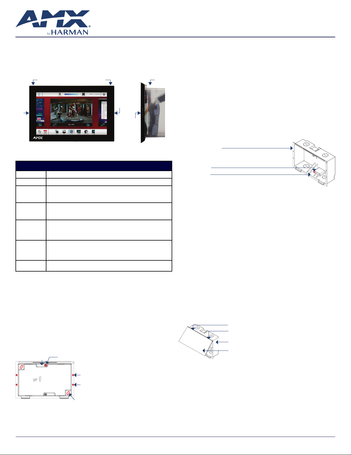
The MD-702 (FG5969-55BL) 7” Modero G5 Wall Mount Touch Panel features
the G5 Graphics Engine, Quad Core Processor, and a capacitive multi-touch
display. This panel now supports two operational modes: as a customizable
Modero panel to be congured with RPM or TPDesign5/Netlinx Studio, or as
an Acendo Book scheduling panel which connects directly to popular room
scheduling software.
Left
LED
FIG. 1 MD-702
Sleep button Backbox
Optional Microphone
Right
LED
Side
LED
(side view)
Product Specifications
MD-702 SPECIFICATIONS
Dimensions (HWD) 4 7/8” x 7 3/8” x 2 1/4” (123.9mm x 187.5mm x 58mm), with Backbox
Weight 1.05 lbs (.680 Kg), with Backbox / 0.8 lbs (.363 Kg), without Backbox
Power
Consumption
External Power
Supply Required
Certications • FCC Part 15 Class B
Environmental • Temperature (Operating): 32°F to 104°F (0°C to 40°C)
Included
Accessories
• Full-On: 11.5W maximum
• Standby: 5.8W
• Shutdown: 1W
• Start-Up Inrush Current: Not applicable due to PoE standard
Optimal performance requires use of one of the following AMX PoE power supplies (not
included):
• PS-POE-AF-TC, PoE Injector, 802.3AF Compliant (FG423-83)
• NXA-ENET8-POE+, Gigabit PoE Ethernet Switch (FG2178-64)
• AUS/NZ
• EN 55032:2012/AC:2013 Class B
• CISPR32:2015
• Brazil InMetro
• Temperature (Storage): 4°F to 140°F (-20°C to 60°C)
• Humidity (Operating): 20% to 85% RH
• Humidity (Storage): 5% to 85% RH
• Power (“Heat”) Dissipation: On: 27.3 BTU/hr, Standby: 10.9 BTU/hr
• Installation Template, 7” Wall Mount (68-2265-02)
• Backbox, Wall Mount, 7” (60-2265-39)
• IEC/EN-60950
• KN32 Class B
• CAN-ICES-3(B)/NMB-3(B)
• UL 60950-1
• RoHS/WEEE compliant
MD-702 Installation
The MD-702 can be installed via several mounting options: Use the included
clear plastic Backbox to attach the panel to most standard wall materials. Other
optional AMX mounting solutions include the MSA-MMK2-07 Multi Mount Kit, the
MSA-AMK2-07 Any Mount Kit, CB-MXSA-07 Rough-In Box and the MSA-RMK-07
Rack Mount Kit. Refer to the Quick Start Guide included with each mounting kit
for instructions.
Power Over Ethernet
Power for the MD-702 is supplied via Power Over Ethernet (PoE), utilizing an
AMXcertied PoE injector such as the PS-POE-AF-TC PoE Injector (FG423-83).
Connect the incoming Ethernet cable to the RJ-45 port on the MD-702.
Plastic Backbox
The MD-702 comes with a clear plastic Backbox (FIG. 2). This Backbox can be
used to mount the touch panel into most standard wall materials. The Backbox
can also used to mount the panel into other mounting options.
Locking Tab (x2)
Locking Tab screw (x2)
Mounting holes (X4) for use with mounting screws
(not included)
Use these mounting holes to install the Backbox
into thin walls (less than 0.5” thick) or solid
surfaces
Mounting holes for installing the Backbox into a Rough-In Box (screws not included)
FIG. 2 7” BACKBOX (FRONT VIEW)
STEP 1: Install the Plastic Backbox
Use the included Installation Template to determine the placement of the
Backbox in the mounting surface. The outside edges of the template are the
same dimensions as the touch panel, which allows you to troubleshoot possible
conicts with wall edges, doors, and other potential obstacles.
1. After ensuring proper placement, cut an opening in the mounting surface
for the Backbox, using the included Installation Template as a guide
Note: Consider making the actual cutout opening slightly smaller than the
provided dimensions. This provides a margin of error if the opening needs to be
expanded. Too little wall material removed is always better than too much.
2. Thread the incoming cables (Ethernet and Micro-USB) from their terminal
locations through the surface opening, leaving enough slack in the wiring to
accommodate any re-positioning of the panel.
3. Remove the Backbox knockouts and thread incoming cables through
the knockouts.
4. Gently push the Backbox into the mounting surface.
• This Backbox uses two Locking Tabs to secure the Backbox to the wall.
For typical mounting surfaces, such as drywall, the locking tabs are the
primary method for securing the Backbox to the wall.
• To ensure a stable installation, the thickness of the wall material must be a
minimum of .50 inches (1.27cm) and a maximum of .875 inches (2.22cm).
The mounting surface should also be smooth and at. For thin walls or
solid surfaces, use mounting screws (not included) - see FIG. 2.
5. Extend the Locking Tabs by tightening the Locking Tab screws until snug (FIG. 3):
7” Wall Mount Backbox
Locking Tab screw (x2) - tighten to
extend both of the Locking Tabs
(max torque = 5 IN-LB)
Locking Tab (x2)
FIG. 3 7” BACKBOX - LOCKING TAB AND LOCKING TAB SCREW (X2)
CAUTION: The maximum recommended torque to screw in the locking
tabs on the plastic Backbox is 5 IN-LB [56 N-CM]. Excessive torque on the
tab screws can strip out the locking tabs or damage the Backbox.
• Extend the Locking Tabs only AFTER the Backbox is inserted into the wall.
• When installing the Backbox, make sure that it is positioned correctly.
• The Backbox is clear to allow visual conrmation that the tabs have been
extended and are gripping the wall, as well as in assisting with removal
if necessary.
STEP 2: Insert Connectors on the Touch Panel
1. Before installing the touch panel into the Backbox, connect the Ethernet
and USB cables to the rear of the panel.
2. Remove power at the terminal end before continuing with the installation.
Note: Do not disconnect the connectors from the touch panel. The unit must
be installed with the attached connectors before being inserted into the
mounting surface.
STEP 3: Secure the Touch Panel To the Backbox
The Backbox uses notches on the front edges (top and bottom) to secure the
panel into place. Follow the steps below to install the panel into the Backbox,
starting the upper edge of the touch panel:
UPPER TABS FIRST
1. Center the top edge of the touch panel against the upper outside edge of the
Backbox and latch the top of the panel onto the Backbox top-hooks (FIG. 4):
Use the top-hooks on the top edge of the Backbox to
latch the top of the touch panel into place
Plastic Backbox
MD-702 Touch Panel
FIG. 4 ENGAGING THE TOP EDGE OF THE PANEL WITH THE TOP HOOKS ON THE BACKBOX
2. Gently press the top edge of the touch panel into place to engage the
panel’s notches and the top-hooks on the Backbox.
LOWER TABS- Gently Press Into Place
1. Swing the bottom edge of the touch panel into position until it rests against
the lower outside edge of the Backbox.
Note: If a gap is observed between the panel and the Backbox, or binding is
felt while locking down the panel, stop and verify there are no cables in the
way. Do not force the panel into position, or the touch screen or the panel
electronics may be damaged.
2. Gently press the bottom edge of the panel gently but rmly and ONLY IN
THE PLACES INDICATED BELOW until the tabs click into place to secure the
panel (FIG. 5):
AV FOR AN IT WORLD
®
Page 2
MD-702 Touch Panel
Plastic Backbox
Gently press the bottom edge of the touch panel in these places
(simultaneously to snap the bottom edge of the panel into place
and secure the panel in the Backbox) SEE NOTES BELOW
FIG. 5 SNAPPING THE BOTTOM EDGE OF THE PANEL INTO THE BACKBOX
3. Reconnect the terminal Ethernet and USB to their respective locations on
either the Ethernet port or NetLinx Master.
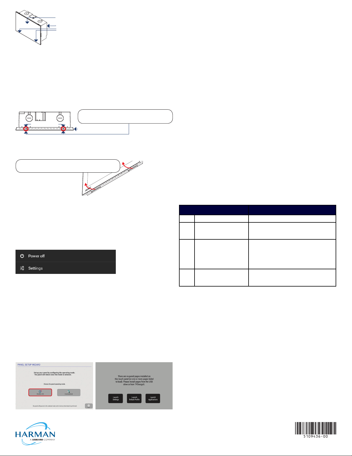
Removing the MD-702 from the Backbox
The tabs on the bottom edge of the Backbox lock down the MD-702 and must
be unlatched in order to remove the touch panel from the Backbox. To do this,
you’ll need a small athead screwdriver.
1. With a small athead screwdriver, carefully press straight into the access
holes on the bottom of the bezel (near the center of the bottom tabs) to
disconnect the two bottom clips (FIG. 6):
Backbox (bottom view)
2.
Bottom Clips
Insert screwdriver straight into access holes to push the
bottom clips in andaway from the panel to release
the bottom edge
Bezel (bottom edge)
FIG. 6 MD-702/BACKBOX ASSEMBLY - BOTTOM VIEW
2. Grasp the bottom of the panel and pull gently outward until the side of the
panel is free of the snap. Use your other hand to stabilize the front of the
touch panel (FIG. 7):
Lift the bottom edge of the panel by the plastic bezel
and gently rotate up and away from the base
Note: To avoid damaging the panel,
always pull on the plastic bezel - do
not pull on the glass.
FIG. 7 MD-702/BACKBOX ASSEMBLY (RELEASING THE BOTTOM EDGE OF THE PANEL)
Note: Always pull on the frame of the touch panel. NEVER pull on the glass edge.
3. With the edge of the touch panel free, carefully lift up and out to remove
the touch panel from the Backbox. Be careful not to pull on the cables or
connectors.
Note: Hold the panel to
prevent it from falling once
the bottom edge is free
Powering On/Off Modero G5 Panels
Modero G5 touch panels may be powered on by touching and holding the
Sleep button. To power off the panel, press and hold the Sleep button, and
select Power Off on the on-screen menu (FIG. 8):
FIG. 8 SLEEP BUTTON - PRESS AND HOLD TO ACCESS POWER OFF/SETTINGS OPTIONS
Selecting Modero Or Acendo
MD-702/MD-1002 panels will be congured in the eld to operate as either a
Modero G5 panel or as an Acendo Book scheduling panel.
Upon rst boot, a wizard application allows the user to select the operating
mode for the device to run – either Modero G5 or Acendo Book
Once the operating mode is congured, that operating mode will be set from then on.
In order to change operating mode after one was selected, a Factory Data
Reset will reset the operating mode back to a point to which the user can select
the operating mode using the wizard application.
Select Operational Mode
Select either Modero G5 or Acendo
Book mode (will prompt panel reboot).
This option is presented for brand new
units or a unit that is reset to factory
settings. (FIG. 9)
When Modero G5 is selected (in Fig
9), this is the default screen until a UI is
loaded via USB or TPDesign5.
Configuration and Programming
Modero G5 touch panels are equipped with a Settings menu that provides the
ability to congure various features on the panels. To access the Settings menu,
press and hold the Sleep button, and select Settings.
Note: Information on the Settings menu, panel conguration, and programming
is provided in the Modero G5 Programming Guide, available at www.amx.com.
Setting the Panel’s Device Number and Device Name
1. In the Settings menu, select NetLinx. This opens a password keypad.
2. Enter the panel password into the keypad (the default is 1988) and select
OK to access the NetLinx page.
3. Press Device Number to open the NetLinx editing window.
4. Enter a unique Device Number assignment for the panel and press OK.
5. Enter a unique Device Name assignment for the panel and press OK.
Configuring the Panel’s IP Address
These steps congure the panel to communicate with a network; it is still necessary
to connect to the NetLinx Master (see Connecting to a NetLinx Master below).
Network Communication via DHCP
1. In the Ethernet page, press DHCP/Static eld to open the DHCP/Static
window. Note that DHCP is the default setting.
2. Select Host Name, enter the new host name
3. Press OK to save changes.
Network Communication via Static Address
1. In the Ethernet page, press DHCP/Static to open the DHCP/Static window.
2. Select Static to open the Static IP window.
3. Press any eld to open a keypad or keyboard (depending on the eld), and
enter the appropriate network address information.
4. Press OK to save your changes and return to the Ethernet page.
Connecting to a NetLinx Master
To establish the type of connection to make between the panel and the
NetLinx Master:
1. In the NetLinx page, press Mode to choose the connection mode (URL,
Listen or Auto):
CONNECTION MODES
Mode Description Procedures
URL The device connects to the target
Master’s IP address via a TCP
connection.
Listen This mode allows the panel to“listen”
for the Master’s communication
signals.
Note that in this mode, the System
Number and Master IP/URL elds are
read-only.
Auto Use this mode when both the panel
and the NetLinx Master are on the
same Subnet.
2. If password security is enabled on the target Master, enter the Username
and Password:
a. Select Username to open the NetLinx window.
b. Enter the Username and Password required by the Master.
c. Press OK to save changes and return to the NetLinx page.
1. Select URL in the Mode menu.
2. Enter the Master IP/URL, Master Port Number, and
Username/Password (if required by the Master).
3. Press OK to save changes.
1. Select Listen in the Mode menu.
2. Conr m the panel’s IP address is on the Master’s URL list
(via NetLinx Studio).
3. Press OK to save changes.
Note: The Host Name (set on the Ethernet page), can be
used to locate the panel on the Master (particularly useful for
DHCP connections where the IP address
can change).
1. Select Auto in the Mode menu.
2. Enter the System Number and User name and Password
(if applicable).
3. Press OK to save changes.
Related Software and Additional Documentation
(at www.amx.com)
• Programming the Modero G5 touch panels requires the use of either Rapid
Project Maker (RPM) or the latest version of Netlinx Studio and TPDesign5,
both available to download at www.amx.com. Refer to the NetLinx Studio
and TPDesign5 online help for information.
• For information on designing touch panel pages intended to optimize the
Modero G5 experience, refer to the G5 Considerations Guide.
• For additional information on the MD-702 panel, refer to the Modero G5
Touch Panel Instruction Manual.
• For detailed information on the Settings menu as well programming
information and instructions on upgrading rmware, refer to the Modero G5
Programming Guide.
• Detailed specications drawings for the MD-702 are available to download
from www.amx.com.
FIG. 9 OPERATING MODE SELECTION
© 2018 Harman. All rights reserved. Modero X and Modero X Series, AMX, AV FOR AN IT WORLD, and HARMAN, and their respective logos are
registered trademarks of HARMAN. Oracle, Java and any other company or brand name referenced may be trademarks/registered trademarks
of their respective companies. AMX does not assume responsibility for errors or omissions. AMX also reserves the right to alter specications
without prior notice at any time. The AMX Warranty and Return Policy and related documents can be viewed/downloaded at www.amx.com.
3000 RESEARCH DRIVE, RICHARDSON, TX 75082 AMX.com | 800.222.0193 | 469.624.8000 | +1.469.624.7400 | fax 469.624.7153
AMX (UK) LTD, AMX by HARMAN - Auster Road, Clifton Moor, York, YO30 4GD United Kingdom • +44 1904-343-100 • www.amx.com/eu/
FIG. 10 MODERO G5 DEFAULT SCREEN
LAST REVISED: 10/09/2018
 Loading...