

Page 1
QUICK START GUIDE
NCITE-813AC 8:1x3 Digital Video Presentation System
Overview
This guide applies to the Incite NCITE-813AC 8:1x3 Presentation System (FG1901-
16). The purpose of this document is to illustrate how to set up a device in its
simplest conguration by a trained technician.
What?s in the Box?
The following items are included with the NCITE-813AC:
•(1) Power Cord, Universal
• (2) Rack Ear Mounting Brackets (2 RU)
• (8) #6-32 x 1/4” screws
• (4) rubber feet
• (1) Commoning Strip, Cypher, 8 Pos., 3.5 mm, Phoenix Connector
• (2) 2-pin 5mm connectors
• (14) 5-pin connectors
• (2) 3-pin connectors
• (1) 4-pin 3.5mm connector
• (1) 6-pin 3.5mm connector
• (2) 8-pin 3.5mm connectors
• (1) 10-pin 3.5mm connector
• (2) CC-NIRC, IR Emitter with 3.5mm Phoenix Connector (FG10-000-11)
Environmental Requirements
The environmental requirements for the NCITE-813AC are as follows:
• Operating Temperature: 32° F (0° C) to 104° F (40° C)
• Storage Temperature: 4° F (-15° C) to 140° F (60° C)
• Operating Humidity: 5% to 85% RH
Getting Connected
Once the NCITE-813AC is powered on, you can connect to it through its IP
address.
Using the Front Panel Buttons
You can access the conguration settings for the device by using the MENU
ON/OFF, SELECT, and navigational buttons on the front panel of the device.
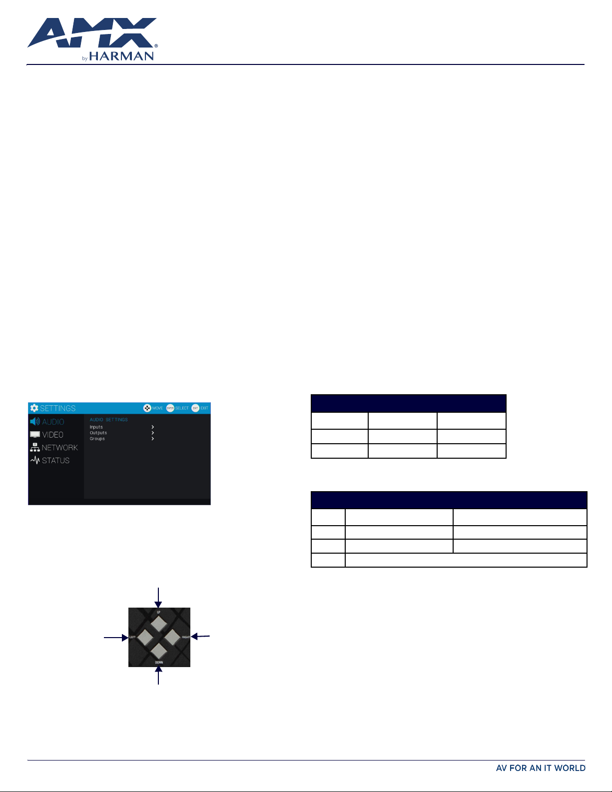
Pressing the MENU ON/OFF button opens the On-Screen menu (FIG. 1) on the
connected output device.
FIG. 1 ON-SCREEN MENU
Locating the IP Address of the NCITE-813AC
You can locate the IP address of the NCITE-813AC by using the buttons on the
front panel of the unit. You can nd the IP address in the On-Screen Menu (OSM)
on the video output connected to the presentation system. Perform these steps
to locate the IP address of the unit:
1. Press the MENU ON/OFF button on the front panel of the unit to open the
On-Screen menu.
2. Use the UP and DOWN navigational arrow buttons to navigate to the
Network menu.
3. Arrow right once to access the options under the Network menu and view
the IP address. Note the IP address for future reference.
NOTE: You can use the Network menu to verify current TCP/IP settings using the
UP and DOWN navigational buttons.
Changing the IP Address Once You Are Connected
Perform these steps to change the IP address once you are connected to the
controller:
NOTE: Ensure the PC you are using to connect to the controller has the latest
version of NetLinx Studio 4.0 installed on it.
1. Set the IP address on your PC to the same network the controller is currently
on.
2. In NetLinx Studio, select Diagnostics > Network Addresses from the menu
bar to open the Network Addresses dialog.
3. Click Get IP Information to enable the elds for editing.
4. Enter the System, Device (0 for NetLinx Masters), and Host Name
information.
5. To specify a network IP address, select Specify IP Address.
6. Enter the IP parameters into the available elds.
7. Click Set IP Information to retain the pre-reserved IP Address to the Master.
8. Click Reboot Device to nish assigning the IP address to the Master, and
click OK to close the dialog.
Default Settings
The following sections list the default settings for the controller.
Default User Names and Passwords
The following table lists the default user names and passwords for accessing the
presentation system through NetLinx Studio or the WebConsole.
Press the SELECT button to change an audio/video setting while you are using
the
On-screen menu on the selected output device. When using the on-screen
menu, use the navigational buttons to cycle through audio and video settings
(depending on the menu.)
Use the Navigational buttons to traverse the available options and change their
values. FIG. 2 displays the navigational function of each button.
Move up to next menu conguration parameter
Decrease value, or
change the state of
the selected parameter
Increase value, or
change the state of the
selected parameter
Move down to next menu conguration parameter
FIG. 2 NAVIGATION BUTTONS
DEFAULT USER NAMES AND PASSWORDS
NetLinx Studio netlinx password
WebConsole administrator password
User Name Password
Default IP Addresses
The following table lists the default IP addresses for the presentation system.
DEFAULT IP ADDRESSES
Static IP 192.168.1.3 255.255.255.0
ICSLAN 198.18.0.1 255.255.0.0
Link-local 169.254.x.y, where x and y are the least signicant two octets of the MAC address.
IP Address Subnet
Configuration
All items in this section require accessing the front panel of the presentation
system.
Accessing the WebConsole
The NCITE-813AC has a built-in WebConsole that allows you to make various
conguration settings via a web browser on any PC with access to the device.
The WebConsole consists of a series of web pages that are collectively called the
“Master Conguration Manager”. Refer to the
trollers WebConsole & Programming Guide
any PC with access to the LAN that the target presentation system resides on:
1. Open a web browser and type the IP Address of the target presentation
system in the Address Bar.
NX Series NetLinx Integrated Con-
for details on the WebConsole. From
Page 2
2. Press Enter to access WebConsole for the presentation system. The initial
view is the WebControl page.
FIG. 3 WEBCONSOLE (MAIN PAGE) Selecting an Audio Test Tone
Selecting a test tone for your input source can help determine if you have your
audio devices connected correctly. Perform these steps to select a test tone:
1. Connect to your Presentation System via WebConsole.
2. Select the Switcher tab.
3. On the Switcher page, select the Conguration tab. Select an output on the
left side of the WebConsole.
4. Click the Audio Out tab.
5. In the Port-Specic area, select Enable under Test Tone Enable.
Selecting a Video Test Pattern
Selecting a test pattern for your input source can help determine if the displays
are connected correctly. Perform these steps the select a test pattern:
1. Connect to your Presentation System via WebConsole.
2. Pass your pointer device over the Switcher tab so the drop-down menu
appears, then select Conguration. The Conguration page opens, and the
Video Out tab appears by default.
3. In the Display Settings section, use the Logo/Test Pattern drop-down menu
to select a test pattern or logo image to display on the video output.
Enabling Security To enable security:
1. Select the Security tab on the WebConsole. The System Security Details
appear.
2. Click the Enabled check box to enable security and activate the Access
options.
3. Select the Access options which you want to require a login and password.
4. Congure users and groups as necessary.
Wired 802.1x Security
The NCITE-813AC supports wired 802.1x, an IEEE Standard for Port-based Network
Access Control. To enable wired 802.1x, you must load an 802.1x certicate le
to your controller using NetLinx Studio. Once you add the certicate le to your
workspace, NetLinx Studio transfers the le to the appropriate directory on the
controller.
1. Click to select (highlight) a System (in the Workspace tab of the Workspace
Bar).
2. Right-click on the Other folder to access the Other File Folder context menu,
and select Add Existing Other File.
3. In the Add Existing Other File dialog, locate and select the certicate le
(.crt) that you want to add to the selected System. Change the Files of Type
option to All Files (*.*) to look for other le types, if necessary.
4. Click Open to access the File Properties dialog, where you can view/edit
general le information for the selected le.
5. Click OK to add the le to the selected System. The le should now appear
in the Other folder under the selected System.
Hardware Information
This section lists important hardware information for the NCITE-813AC.
Port Numbers
The following table lists the port numbers for the NCITE-813AC:
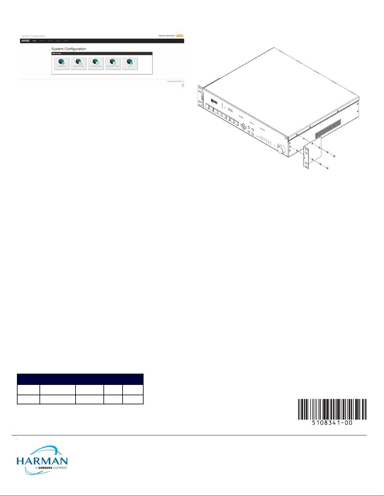
Mounting the NCITE-813AC into an Equipment Rack
The NCITE-813AC occupies two rack units (2 RU) in a standard equipment rack.
Install the included rack mounting brackets using the supplied mounting screws
prior to securing the unit in the rack (FIG. 4).
FIG. 4 ATTACHING THE MOUNTING BRACKETS TO THE NCITE-813AC
CAUTION: The NCITE-813AC should not be installed in enclosed spaces. ALWAYS ensure
that the rack enclosure is adequately ventilated. Do not block any ventilation openings.
It is recommended that you leave 1 RU of space above the device when you install it in
a rack. DO NOT stand other units directly on top of the device when it is rack mounted, as
this will place excessive strain on the mounting brackets.
ALWAYS ensure that the rack enclosure is adequately ventilated. Do not block any
ventilation openings. Sucient airow must be achieved (by convection or forced-air
cooling) to satisfy the ventilation requirements of all the items of equipment installed
within the rack.
NOTE: Connect the LAN port to a LAN with DHCP before powering up the device.
Additional Documentation
Additional documentation for this device is available at www.amx.com.
• Refer to the
additional details on installing, wiring, and updating the rmware for your
device.
• Refer to the
Programming Guide
Incite Digital Video Presentation Systems Instruction Manual
NX Series NetLinx Integrated Controllers WebConsole &
for detailed conguration instructions.
for
NCITE-813AC PORT NUMBERS
RS-232 RS-422/485 IR/Serial I/O Relay
2-4 1 11-14 22 21
© 2018 Harman. All rights reserved. AMX, AV FOR AN IT WORLD, HARMAN, and their respective logos are registered trademarks of HARMAN.
Oracle, Java and any other company or brand name referenced may be trademarks/registered trademarks of their respective companies.
AMX does not assume responsibility for errors or omissions. AMX also reserves the right to alter specications without prior notice at any time.
The AMX Warranty and Return Policy and related documents can be viewed/downloaded at www.amx.com.
3000 RESEARCH DRIVE, RICHARDSON, TX 75082 AMX.com | 800.222.0193 | 469.624.8000 | +1.469.624.7400 | fax 469.624.7153 AMX (UK) LTD, AMX
by HARMAN - Unit C, Auster Road, Clifton Moor, York, YO30 4GD United Kingdom ? +44 1904-343-100 ? www.amx.com/eu/
REV: A
Initial Release: 03/31/2018
 Loading...