

Page 1
Quick Start Guide
Mio Modero DMS Conduit Box
Overview
For more detailed installation, configuration, programming, and operating
instructions, refer to the Mio Modero DMS & Mio Modero DMS Pinnacle
instruction manual available on-line at www.amx.com.
Mio Modero DMS Conduit Box (FG039-11) Specifications
Dimensions (HWD) 6.25 (158.8 mm) x 3.08 (78.3 mm) x 3.50 (88.9 mm)
Weight • Conduit box - .85 lbs (.39 kg)
Included
Accessories:
Other AMX
Equipment:
• Magnetic Post Housing - .10 lbs (.05 kg) (MA2408-01)
• 4 screws, #2-56 X .250 (800105)
• 1 ground screw, #8-32 X 3/8 wafer head, green (80-0149)
• Mounting template (68-2408-01)
• Mio Modero DMS (FG2408-01xx)
• Mio Modero DMS Pinnacle (FG2408-02xx)
xx indicates color
Installation
It is recommended that you cutout the surface slightly smaller than what is
outlined in the installation drawings so that you can make any necessary cutout
adjustments.
Before you begin, if you are using the 2-pin power connector, verify that the
terminal end of the power cable is not connected to a power source.
Note: The device and conduit box must have an Earth ground.
If assembled, pull the Mio Modero DMS from the conduit box.
Rough-in Installation of the Conduit Box
1. Remove the tabs for the expansion clip installation from the conduit box by
bending back and forth with pliers. See FIG. 1.
2. Use screws through the rough-in tabs to the stud. The conduit box is 3.5"
(8.89 cm) deep. The front of the conduit box should be flush with the front
surface of the sheetrock. While the conduit box can be recessed it should
never stand proud to the surface.
3. Run 12V or CAT5/6 cable and an Earth ground wire into the conduit box.
Locations to run power wiring into the conduit box are shown in FIG. 1.
Expansion clip
Rough-in
installation tabs
Earth
ground
point
Keyhole CAT5/6
and 12V access
installation tabs
Expansion Clip Installation of the Conduit Box
The expansion clip installation method can be used for podium or other flat
surface installations.
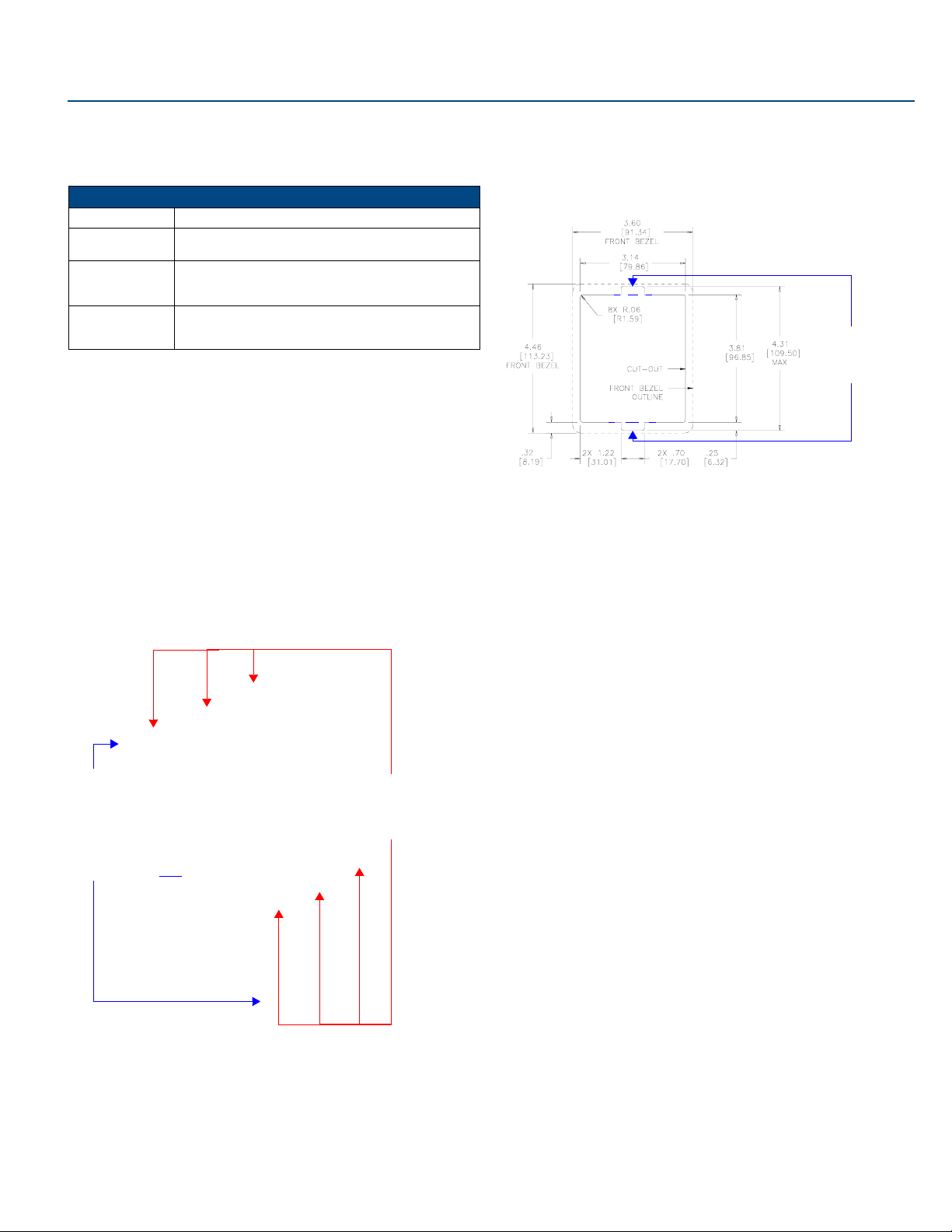
1. Cut out the surface for the Mio Modero DMS conduit box using the
dimensions shown in FIG. 2. A template is included to help you determine
dimensions.
Notches are only
required for
expansion clip
installations
FIG. 2
Mio Modero DMS Cutout Installation Dimensions
2. Remove the tabs for the rough-in installation from the conduit box by
bending back and forth with pliers. See FIG. 1.
3. Thread the CAT5/CAT6, the Earth ground wire and, if necessary, the power
cables through one of the provided breakaway access points on the
conduit box. Leave enough slack in the wiring to accommodate any
re-positioning of the unit.
4. Thread the 2 drywall screws through the 2 locations center on both top and
bottom of the conduit box (FIG. 1) and then through the expansion clips.
5. Insert the conduit box and expansion clips into the cutout until the rim of the
conduit box is flush against the wall.
6. Tighten the 2 drywall clip sets (screws and clips) until the conduit box is
flush against the wall.
7. Insert the provided cardboard paint shield into the conduit box if the Mio
Modero DMS will not be installed at this time.
Installing the Conduit Box without the Use of Tabs
A brick and mortar installation environment is a great example where no tabs are
required.
1. Remove both the tabs for the rough-in installation and expansion clip
installation from the conduit box by bending back and forth with pliers. See
FIG. 1.
2. Thread the CAT5/CAT6, the Earth ground wire and, if necessary, the power
cables through one of the provided breakaway access points on the
conduit box. Leave enough slack in the wiring to accommodate any
re-positioning of the unit.
3. Insert the provided cardboard paint shield into the conduit box.
4. While conducting this installation, confirm nothing gets into the conduit box,
i.e., mortar.
FIG. 1
Mio Modero DMS Conduit Box
4. Insert the cardboard paint shield into the conduit box if the Mio Modero
DMS will not be installed at this time.
Page 2
Mounting the Magnetic Post Housing on a Mio Modero DMS
If the Mio Modero does not already have the magnetic post housing attached,
follow these steps. The Mio Modero DMS will not stay in the conduit box
without the magnetic post housing. Only the new conduit box can be used with
the magnetic posts.
To avoid any damage to the electronic component, installation must be
performed in an ESD safe environment.
1. If in the wall, remove the Mio Modero DMS from the conduit box. Place a
flathead screwdriver between the tab of the conduit box and the notch of
the Mio Modero DMS and pop the two apart. Pull the bottom of the unit
out (pivoting on the top clip) until it seems to bind against the shielding;
while keeping the unit at this angle, pull the top of the unit away from the
top clip.
2. Place the Mio Modero DMS unit face down on a flat surface.
3. Unscrew the 4 points illustrated in FIG. 3.
4 screws
Screw points for
magnetic mounting.
(Side view)
FIG. 5 Rear and side view of magnetic housing
7. Insert the provided cardboard paint shield into the conduit box if the Mio
Modero DMS will not be installed at this time.
FIG. 3 Rear View of Mio Modero DMS
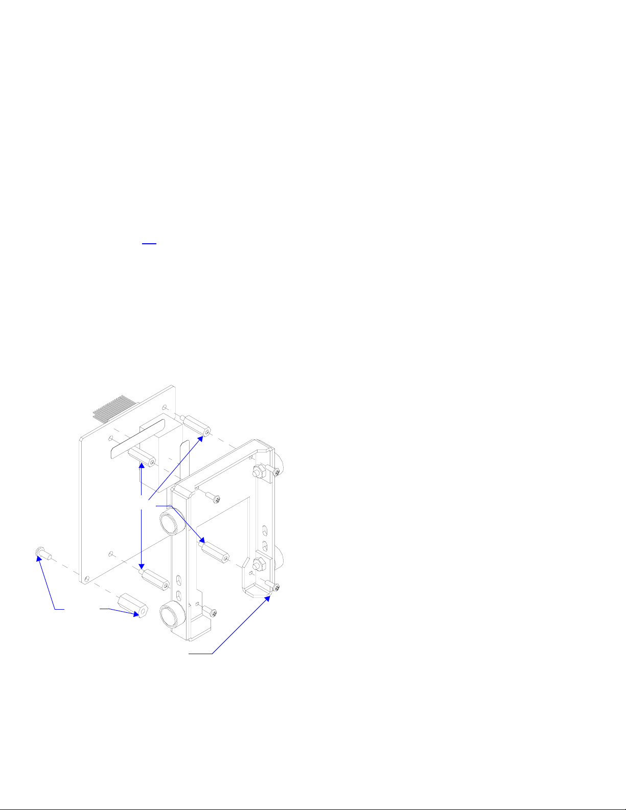
4. Screw 4 standoffs provided with the conduit box kit into the holes from the
previous step.
5. Place the hex post over the hole illustrated in FIG. 4 and fasten it down
with the screw on the bottom side of the board.
4
standoffs
Hex Post
and
Screw
Magnetic Post Housing
FIG. 4 4 Standoffs and Hex Post locations
6. Place and fasten the magnetic housing onto the standoffs as illustrated in
FIG. 5. Note the orientation of the cutout on the magnetic housing in
relation to the Mio Modero DMS board, it should not be mounted in any
other fashion. Use either the 4 screws removed in step #3 or the 4
screws provided with the kit (for those that already lost the other 4
screws).
For full warranty information, refer to the AMX Instruction Manual(s) associated with your Product(s).
©2006 AMX. All rights reserved. AMX and the AMX logo are registered trademarks of AMX.
3000 RESEARCH DRIVE, RICHARDSON, TX 75082 • 800.222.0193 • fax 469.624.7153 • technical support 800.932.6993 • www.amx.com
AMX reserves the right to alter specifications without notice at any time.
037-004-2985 8/06
93-2408-20 REV: A
 Loading...