

Page 1
Operation/Reference Guide
ViewStat
Color Communicating Thermostat
ENV-VST-C
HVAC Controls
Last Updated: 12/12/2008
Page 2

AMX Limited Warranty and Disclaimer
All products returned to AMX require a Return Material Authorization (RMA) number. The RMA number is
obtained from the AMX RMA Department. The RMA number must be clearly marked on the outside of each
box. The RMA is valid for a 30-day period. After the 30-day period the RMA will be cancelled. Any shipments
received not consistent with the RMA, or after the RMA is cancelled, will be refused. AMX is not responsible
for products returned without a valid RMA number.
Warranty Repair Policy
• AMX will repair any defect due to material or workmanship issues during the applicable warranty period at no cost to the AMX
Authorized Partner., provided that the AMX Authorized Partner is responsible for in-bound freight and AMX is responsible for
out-bound ground freight expenses.
• The AMX Authorized Partner must contact AMX Technical Support to validate the failure before pursuing this service.
• AMX will complete the repair and ship the product within five (5) business days after receipt of the product by AMX. The AMX
Authorized Partner will be notified if repair cannot be completed within five (5) business days.
• Products repaired will carry a ninety (90) day warranty or the balance of the remaining warranty, whichever is greater.
• Products that are returned and exhibit signs of damage or unauthorized use will be processed under the Non-Warranty Repair
Policy.
• AMX will continue to provide Warranty Repair Services for products discontinued or replaced by a Product Discontinuance
Notice.
Non-Warranty Repair Policy
• Products that do not qualify to be repaired under the Warranty Repair Policy due to age of the product or Condition of the product may be repaired utilizing this service.
• The AMX Authorized Partner must contact AMX Technical Support to validate the failure before pursuing this service.
• Non-warranty repair is a billable service.
• Products repaired under this policy will carry a ninety (90) day warranty on material and labor.
• AMX will notify the AMX Authorized Partner with the cost of repair, if cost is greater than the Standard Repair Fee, within five (5)
days of receipt.
• The AMX Authorized Partner must provide a Purchase Order or credit card number within five (5) days of notification, or the
product will be returned to the AMX Authorized Partner.
• The AMX Authorized Partner will be responsible for in-bound and out-bound freight expenses.
• Products will be repaired within ten (10) business days after AMX Authorized Partner approval is obtained.
• Non-repairable products will be returned to the AMX Authorized Partner with an explanation.
• See AMX Non-Warranty Repair Price List for minimum and Standard Repair Fees and policies.
Page 3

Software License and Warranty Agreement
• LICENSE GRANT. AMX grants to Licensee the non-exclusive right to use the AMX Software in the manner described in this
License. The AMX Software is licensed, not sold. This license does not grant Licensee the right to create derivative works of the
AMX Software. The AMX Software consists of generally available programming and development software, product documentation, sample applications, tools and utilities, and miscellaneous technical information. Please refer to the README.TXT file on
the compact disc or download for further information regarding the components of the AMX Software. The AMX Software is subject to restrictions on distribution described in this License Agreement. AMX Dealer, Distributor, VIP or other AMX authorized
entity shall not, and shall not permit any other person to, disclose, display, loan, publish, transfer (whether by sale, assignment,
exchange, gift, operation of law or otherwise), license, sublicense, copy, or otherwise disseminate the AMX Software. Licensee
may not reverse engineer, decompile, or disassemble the AMX Software.
• ACKNOWLEDGEMENT. You hereby acknowledge that you are an authorized AMX dealer, distributor, VIP or other AMX authorized entity in good standing and have the right to enter into and be bound by the terms of this Agreement.
• INTELLECTUAL PROPERTY. The AMX Software is owned by AMX and is protected by United States copyright laws, patent
laws, international treaty provisions, and/or state of Texas trade secret laws. Licensee may make copies of the AMX Software
solely for backup or archival purposes. Licensee may not copy the written materials accompanying the AMX Software.
• TERMINATION. AMX RESERVES THE RIGHT, IN ITS SOLE DISCRETION, TO TERMINATE THIS LICENSE FOR ANY REASON UPON WRITTEN NOTICE TO LICENSEE. In the event that AMX terminates this License, the Licensee shall return or
destroy all originals and copies of the AMX Software to AMX and certify in writing that all originals and copies have been
returned or destroyed.
• PRE-RELEASE CODE. Portions of the AMX Software may, from time to time, as identified in the AMX Software, include PRERELEASE CODE and such code may not be at the level of performance, compatibility and functionality of the GA code. The
PRE-RELEASE CODE may not operate correctly and may be substantially modified prior to final release or certain features may
not be generally released. AMX is not obligated to make or support any PRE-RELEASE CODE. ALL PRE-RELEASE CODE IS
PROVIDED "AS IS" WITH NO WARRANTIES.
• LIMITED WARRANTY. AMX warrants that the AMX Software (other than pre-release code) will perform substantially in accordance with the accompanying written materials for a period of ninety (90) days from the date of receipt. AMX DISCLAIMS ALL
OTHER WARRANTIES, EITHER EXPRESS OR IMPLIED, INCLUDING, BUT NOT LIMITED TO IMPLIED WARRANTIES OF
MERCHANTABILITY AND FITNESS FOR A PARTICULAR PURPOSE, WITH REGARD TO THE AMX SOFTWARE. THIS LIMITED WARRANTY GIVES LICENSEE SPECIFIC LEGAL RIGHTS. Any supplements or updates to the AMX SOFTWARE,
including without limitation, any (if any) service packs or hot fixes provided to Licensee after the expiration of the ninety (90) day
Limited Warranty period are not covered by any warranty or condition, express, implied or statutory.
• LICENSEE REMEDIES. AMX's entire liability and Licensee's exclusive remedy shall be repair or replacement of the AMX Software that does not meet AMX's Limited Warranty and which is returned to AMX in accordance with AMX's current return policy.
This Limited Warranty is void if failure of the AMX Software has resulted from accident, abuse, or misapplication. Any replacement AMX Software will be warranted for the remainder of the original warranty period or thirty (30) days, whichever is longer.
Outside the United States, these remedies may not available. NO LIABILITY FOR CONSEQUENTIAL DAMAGES. IN NO
EVENT SHALL AMX BE LIABLE FOR ANY DAMAGES WHATSOEVER (INCLUDING, WITHOUT LIMITATION, DAMAGES
FOR LOSS OF BUSINESS PROFITS, BUSINESS INTERRUPTION, LOSS OF BUSINESS INFORMATION, OR ANY OTHER
PECUNIARY LOSS) ARISING OUT OF THE USE OF OR INABILITY TO USE THIS AMX SOFTWARE, EVEN IF AMX HAS
BEEN ADVISED OF THE POSSIBILITY OF SUCH DAMAGES. BECAUSE SOME STATES/COUNTRIES DO NOT ALLOW
THE EXCLUSION OR LIMITATION OF LIABILITY FOR CONSEQUENTIAL OR INCIDENTAL DAMAGES, THE ABOVE LIMITATION MAY NOT APPLY TO LICENSEE.
• U.S. GOVERNMENT RESTRICTED RIGHTS. The AMX Software is provided with RESTRICTED RIGHTS. Use, duplication, or
disclosure by the Government is subject to restrictions as set forth in subparagraph ©(1)(ii) of The Rights in Technical Data and
Computer Software clause at DFARS 252.227-7013 or subparagraphs ©(1) and (2) of the Commercial Computer Software
Restricted Rights at 48 CFR 52.227-19, as applicable.
• SOFTWARE AND OTHER MATERIALS FROM AMX.COM MAY BE SUBJECT TO EXPORT CONTROL. The United States
Export Control laws prohibit the export of certain technical data and software to certain territories. No software from this Site may
be downloaded or exported (i) into (or to a national or resident of) Cuba, Iraq, Libya, North Korea, Iran, Syria, or any other country to which the United States has embargoed goods; or (ii) anyone on the United States Treasury Department's list of Specially
Designated Nationals or the U.S. Commerce Department's Table of Deny Orders. AMX does not authorize the downloading or
exporting of any software or technical data from this site to any jurisdiction prohibited by the United States Export Laws.
This Agreement replaces and supersedes all previous AMX Software License Agreements and is governed by
the laws of the State of Texas, and all disputes will be resolved in the courts in Collin County, Texas, USA. For
any questions concerning this Agreement, or to contact AMX for any reason, please write: AMX License and
Warranty Department, 3000 Research Drive, Richardson, TX 75082.
Page 4

Page 5

Table of Contents
Table of Contents
Introduction ........................................................................................................1
System Components ................................................................................................. 1
Installation and Wiring ........................................................................................3
Disconnecting Power to All HVAC Equipment.......................................................... 3
Selecting the Thermostat Location ........................................................................... 3
Stand-Alone Thermostat Mounting Criteria .................................................................... 3
Remote Temperature Sensors......................................................................................... 3
Removing the Faceplate from the Base .......................................................................... 4
Mounting the Base to a Wall........................................................................................... 4
Wiring the Thermostat .............................................................................................. 5
Wiring Terminals ............................................................................................................. 6
Communication and Equipment Terminal Wiring Definitions.......................................... 7
Preparing Captive Wires ................................................................................................. 7
Wiring Guidelines............................................................................................................ 8
Wiring for AxLink ............................................................................................................ 8
Wiring Diagrams ....................................................................................................... 9
Single Stage Furnace and Single Stage A/C.................................................................... 9
Dual Stage Furnace and Dual Stage A/C....................................................................... 10
Roof Top Unit with Dual Stage Heat and Dual Stage Cool............................................ 10
Boiler and A/C with Separate Transformers .................................................................. 11
Single Stage Heat Pump ............................................................................................... 11
Two Stage Heat Pump .................................................................................................. 12
First Stage Radiant Floor Heat, Second Stage Furnace with Single Stage Cooling....... 13
Installing a Remote Sensor ..................................................................................... 14
Installing the Indoor/Outdoor Remote Sensor.............................................................. 14
Installing the Indoor Flush Mount Sensor...................................................................... 16
Programming ....................................................................................................19
Send Commands ..................................................................................................... 19
Color ViewStat Thermostat Commands .................................................................. 20
5-Day Forecast Commands............................................................................................ 20
AxLink Commands......................................................................................................... 22
AxLink Channels...................................................................................................... 25
AxLink Levels .......................................................................................................... 27
Weather Duet Module ............................................................................................ 28
i!-Weather Setup Pages................................................................................................. 30
Entering Location by Zip Code...................................................................................... 32
Entering Location by Station ID .................................................................................... 32
ViewStat Color Communicating Thermostat
i
Page 6

Table of Contents
Changing Temperature Units ........................................................................................ 32
Changing Wind Speed Units.......................................................................................... 32
Changing Pressure Units ............................................................................................... 32
Auto Refresh Interval Select.......................................................................................... 33
ii
ViewStat Color Communicating Thermostat
Page 7
V
Introduction
The ViewStat Color Communicating Thermostat enables you to completely control your heating,
ventilation, and air-conditioning (HVAC) system. The thermostat provides the current temperature (from
an on-board sensor, a remote sensor, or an average of the on-board and remote sensors), controls and
displays humidity, and displays the current outdoor temperature. The ViewStat Color Thermostat
displays this information on a 3.5" (8.89 cm) color display. In addition, the ViewStat Color Thermostat
provides the current day's weather forecast along with a five-day forecast. The forecast information is
driven from AMX’s i!-Weather application. The thermostat receives the forecast information from a
NetLinx Master, with an internet-enabled IP connection, via AxLink. A three-year subscription to
i!-Weather is included with purchase of the thermostat.
System Components
The following table lists the specifications for the ViewStat Color Communicating Thermostat:
ViewStat Color Thermostat Specifications
Control Voltage 24 VAC (interfaces with a power supply through the R-C terminals)
Switched Voltage 18 – 30 VAC, 57-63 Hz
Maximum Operating Current 2 amps total at rated voltage, through all outputs.
Maximum Surge Current 2.0 A
Internal Battery CR2032 for maintaining real-time clock settings during a power loss.
Control Accuracy ±1.0° F (± 0.56° C)
Temperature Range Maximum displayable indoor temperature: 40° – 99° F (5° – 37° C)
Operating Range 32° – 122° F (0° – 50° C)
Front Panel Components:
Main LCD display 3.5" (8.89 cm) color QVGA (320 x 240) Thin Film Transistor Liquid Crystal
Navigation buttons The Navigation buttons are used to change various parameters on the
Mode/Select button The Mode/Select button is used to navigate through the various thermostat
Circuit Board Components:
Communication and HVAC
Equipment connectors
Enclosure:
Material White plastic and removable front panel. Panel can be painted to match wall
Dimensions (HWD) 5.31" x 3.93" x 1.18" (13.48 cm x 9.98 cm x 2.99 cm)
Introduction
Warning: Exceeding the control voltage may cause damage to the thermostat.
1 amps through any one output.
±3% relative humidity
Maximum displayable outdoor temperature: -40° – 120° F (-40° – 49° C)
Display (TFT-LCD). The main display provides the mode status, temperature,
and system status information.
thermostat, including the temperature setpoints. These buttons are located
beneath the display.
screens, including the weather screens. This button is located beneath the
display.
Terminals with captive-wire connectors that connects to the thermostat, HVAC
equipment, control system, remote sensors, and power supply. See the
Communication and Equipment Terminal Wiring Definitions section on page 7
for more information.
decor.
Warning: If you paint the panel, do not paint over the exposed thermistor.
Doing so can cause the external temperature sensor to work improperly.
iewStat Color Communicating Thermostat
1
Page 8

Introduction
ViewStat Color Thermostat Specifications (Cont.)
Weight 5.29 oz. (150 grams)
Included Accessories ENV-VST-C ViewStat Color Communicating Thermostat Installation Guide
(93-2050-01)
ENV-VST-TSO ViewStat Indoor/Outdoor Temperature sensor (FG2050-22)
Duet i!-Weather application (FG3005-20), three-year subscription
Optional Accessories ENV-VST-TSF ViewStat Indoor Flush Mount Temperature Sensor (FG2050-21)
2
ViewStat Color Communicating Thermostat
Page 9
V
Installation and Wiring
This section covers the installation and wiring of a ViewStat Color Communicating Thermostat system.
120 volts may cause serious injury from electrical shock. Disconnect electrical power to the HVAC
system before starting installation. This system is a low-voltage system.
Improper installation may cause serious injury from electrical shock. This system must be installed
by a qualified contractor in accordance with NEC Standards and applicable local and state codes.
Disconnecting Power to All HVAC Equipment
Since the thermostats wire directly to the HVAC equipment, you must shut off the power at the
equipment. You can generally accomplish this by turning off the disconnect switch located near the
equipment. If an obvious disconnect switch is unavailable, you need to remove the circuit breaker or
shut down the fuse serving the equipment.
Failure to disconnect power could result in damage to the HVAC equipment or thermostats. Leave
the power disconnected until you have made all other electrical connections and checked them for
accuracy.
Installation and Wiring
Selecting the Thermostat Location
Determine if the thermostat will be operating alone, or with remote temperature sensors. If the unit is
stand-alone there are certain measures that must be taken to ensure accurate temperature control.
Stand-Alone Thermostat Mounting Criteria
Mount on an interior wall.
In a room frequently occupied.
At least 18 inches (45.72 cm) from any outside wall.
Approximately 5 feet (1.52 m) above the floor. Check with local building codes for height
requirements in commercial applications.
DO NOT locate the thermostat:
Behind doors, in corners or other dead air spaces.
In direct sunlight or near lamps, appliances or other sources of radiant heat.
On an outside wall or wall exposed to an unconditioned space (i.e. garage, etc.).
In the flow path of a supply register, in stairways or near outside doors.
On a wall where concealed pipes and/or duct work will affect the thermostat.
Near sources of electrical interference such as arcing relay contacts.
Remote Temperature Sensors
When choosing a installation location for the remote sensor, follow the guidelines for placement of the
thermostat, and locate the sensor where its operating range (see the ViewStat Color Thermostat
Specifications table on page 1) will not be violated (i.e. do not install in a cold garage or hot equipment
room). See the Installing a Remote Sensor section on page 14 for details.
iewStat Color Communicating Thermostat
3
Page 10
Installation and Wiring
Removing the Faceplate from the Base
No tools are required to disassemble the thermostat—simply use your hands to pull the front panel off of
the base.
Loss of internal programs may result from static discharge to the thermostat circuit board. Touch a
grounded metal object to discharge any static charge before handling the circuit board.
Mounting the Base to a Wall
You should only mount the ViewStat Color Communicating Thermostat onto a sheetrock wall with the
anchors and screws provided with the unit. There are four screw holes located on the base of the
thermostat.
1. Place the base over the wire hole opening in the wall. Level the base (leveling required for
2. Using the supplied wall anchors, drill 1/4" hole in the center of the marked locations, and tap the
Minimize the wire entry hole size and seal. Drafts from inside the wall could affect temperature
readings.
appearance only) and mark the screw hole mounting locations.
wall anchors into the holes. If using the supplied screws only, drill a 3/32" hole in the center of the
marked locations.
3. Fasten the base to the wall with the supplied screws.
4. Seal the wire entry with caulk, drywall putty, or insulation.
4
ViewStat Color Communicating Thermostat
Page 11

Installation and Wiring
V
Wiring the Thermostat
A qualified HVAC technician should perform these steps to ensure proper termination.
1. Make sure the HVAC system power is off.
2. Strip 1/4" (0.63 cm) of insulation from each wire you are using.
3. Secure the wires into the terminals on the base according to the appropriate wiring diagram, as
described in the following table. Refer to the Wiri n g Diag rams section on page 9. Use color-coding
practices (i.e. white wire to W terminal) whenever possible.
• Single Stage Furnace and Single Stage A/C Refer to the
• Dual Stage Furnace and Dual Stage A/C Refer to the
• Roof Top Unit with Dual Stage Heat and Dual
Stage Cool
• Boiler with A/C with Separate Transformers Refer to the
• Single Stage Heat Pump Refer to the
• Two Stage Heat Pump Refer to the
• First Stage Radiant Floor Heat, Second Stage
Furnace One Stage of Cooling
Single Stage A/C
Stage A/C
Refer to the
Heat and Dual Stage Cool
page 10
Transformers
Pump
on page 12
Refer to the
Second Stage Furnace with Single Stage
Cooling
Single Stage Furnace and
section on page 9
Dual Stage Furnace and Dual
section on page 10
Roof Top Unit with Dual Stage
section on
Boiler and A/C with Separate
section on page 11
Single Stage Heat
section on page 11
Two Stage Heat Pump
First Stage Radiant Floor Heat,
section on page 13
4. Check each wire to ensure it is securely fastened, not broken, and any exposed wires are not
touching each other.
section
iewStat Color Communicating Thermostat
5
Page 12
Installation and Wiring
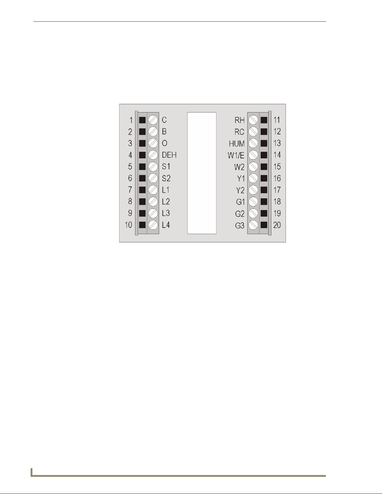
Wiring Terminals
ViewStat Color Communicating Thermostats are equipped with terminals RC, RH, C, Y, W, G, O, B, S1,
S2, L1, L2, L3, and L4. You can use terminals S1 and S2 to accommodate a remote temperature sensor
(see the Installing a Remote Sensor section on page 14 for more information). Terminals L1-L4 connect
to the AxLink cable. The remaining terminals are used to control various types of heating and cooling
systems detailed in the following sections. FIG. 1 displays the layout of the terminals on the thermostat’s
motherboard.
FIG. 1 Terminal Layout
6
ViewStat Color Communicating Thermostat
Page 13
Installation and Wiring
V
Communication and Equipment Terminal Wiring Definitions
The following table lists the communication and equipment terminal wiring definitions.
Communication and Equipment Terminal Wiring Definitions
RH 24 VAC in
RC 24 VAC in for AC relays. If a separate 24 VAC is not supplied
to the RC terminal, you should install a jumper from RH to
RC.
C 24 VAC common
G1 Fan on 1. If you are using a single speed fan, you should
connect it to the G1 terminal. On a multi-speed fan, G1 is the
lowest speed.
G2 Fan on 2. On a multi-speed fan, G2 is the medium speed.
G3 Fan on 3. On a multi-speed fan, G3 is the highest speed.
W1 1st stage heat
W2 2nd stage heat
Y1 1st stage compressor
Y2 2nd stage compressor
B Reversing valve (heat)
O Reversing valve (cool)
DEH Dehumidify
HUM Humidify
S1 External thermistor. The Color ViewStat supports only one
external sensor.
S2 External thermistor. The Color ViewStat supports only one
external sensor.
L1 AxLink PWR
L2 AxLink AxP
L3 AxLink AxM
L4 AxLink GND
Preparing Captive Wires
Follow these steps to connect the wiring into a captive-wire connector:
1. Strip 1/4 inch off the wire insulation for all four wires.
2. Tin 2/3 of the exposed wire.
3. Insert each wire into the appropriate captive-wire connector up to the insulation.
4. Tighten the captive screws to secure the fit in the connector.
iewStat Color Communicating Thermostat
7
Page 14

Installation and Wiring
Wiring Guidelines
The ViewStat Color Communicating Thermostat accepts configuration and weather information from a
NetLink Integrated master via an AxLink bus. Use 18 AWG wire to connect terminals L1-L4 on the
ViewStat to the AxLink device. See the Communication and Equipment Terminal Wiring
Definitions section on page 7 for more information on the terminals on the ViewStat.
The ViewStat Color Communicating Thermostat interfaces with a 24 VAC power supply from the
heating/cooling unit through its RC terminal. You should not connect the power wiring from the
AxLink device to the thermostat with the intent of using the AxLink device to provide power to the
thermostat.
The L1 terminal on the thermostat can accept the AxLink +12VDC wire and you can connect the
wire to the terminal if you want to assure there are no loose wires inside the thermostat, but you
should not power the thermostat by running a jumper to the RC pin.
Wiring for AxLink
Connect the AxLink wiring from the thermostat to the connector on the AxLink device as shown in
FIG. 2.
FIG. 2 AxLink wiring
You can connect the AxLink device to a NetLinx Master by following the instructions in the AxLink
device’s instruction manual.
8
ViewStat Color Communicating Thermostat
Page 15

Installation and Wiring
V
Wiring Diagrams
The following sections display wiring diagrams for the types of HVAC systems that are compatible with
the thermostat:
Single Stage Furnace and Single Stage A/C
FIG. 3 Single Stage Furnace and Single Stage A/C wiring
The thermostat automatically defaults to One Stage Furnace for the HVAC System setting when you
install it. For information about changing the HVAC System setting, consult the ViewSta t C o l o r
Communicating Thermostat User Guide.
iewStat Color Communicating Thermostat
9
Page 16
Installation and Wiring
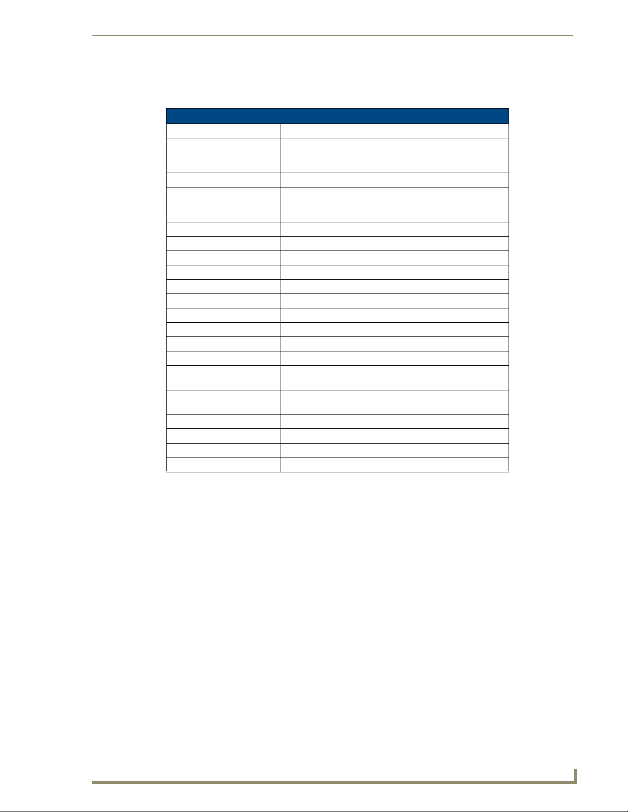
Dual Stage Furnace and Dual Stage A/C
FIG. 4 Dual Stage Furnace and Dual Stage A/C wiring
Roof Top Unit with Dual Stage Heat and Dual Stage Cool
FIG. 5 Roof Top Unit with Dual Stage Heat and Dual Stage Cool wiring
10
ViewStat Color Communicating Thermostat
Page 17
V
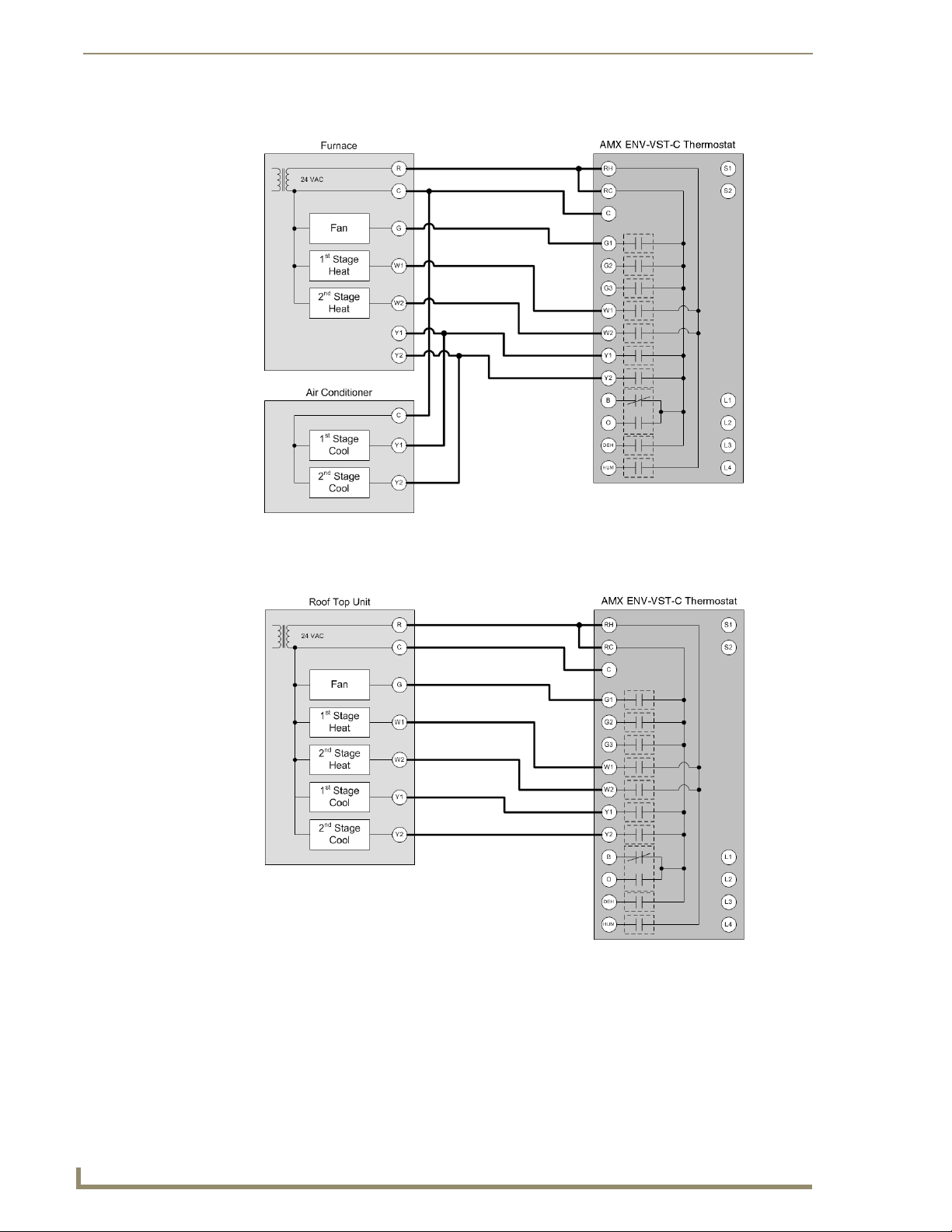
Boiler and A/C with Separate Transformers
Installation and Wiring
FIG. 6 Boiler and A/C with Separate Transformers wiring
Single Stage Heat Pump
FIG. 7 Single Stage Heat Pump wiring
iewStat Color Communicating Thermostat
11
Page 18
Installation and Wiring
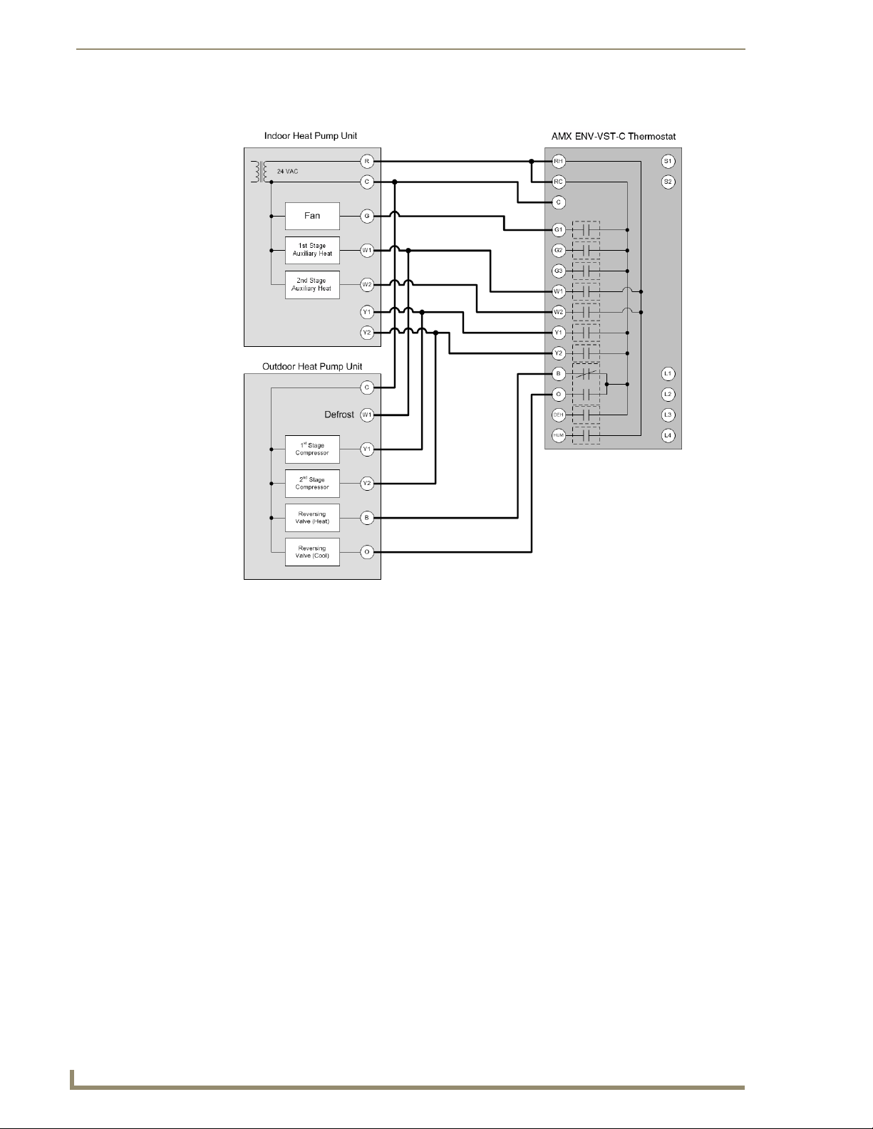
Two Stage Heat Pump
FIG. 8 Two Stage Heat Pump wiring
12
ViewStat Color Communicating Thermostat
Page 19
Installation and Wiring
V
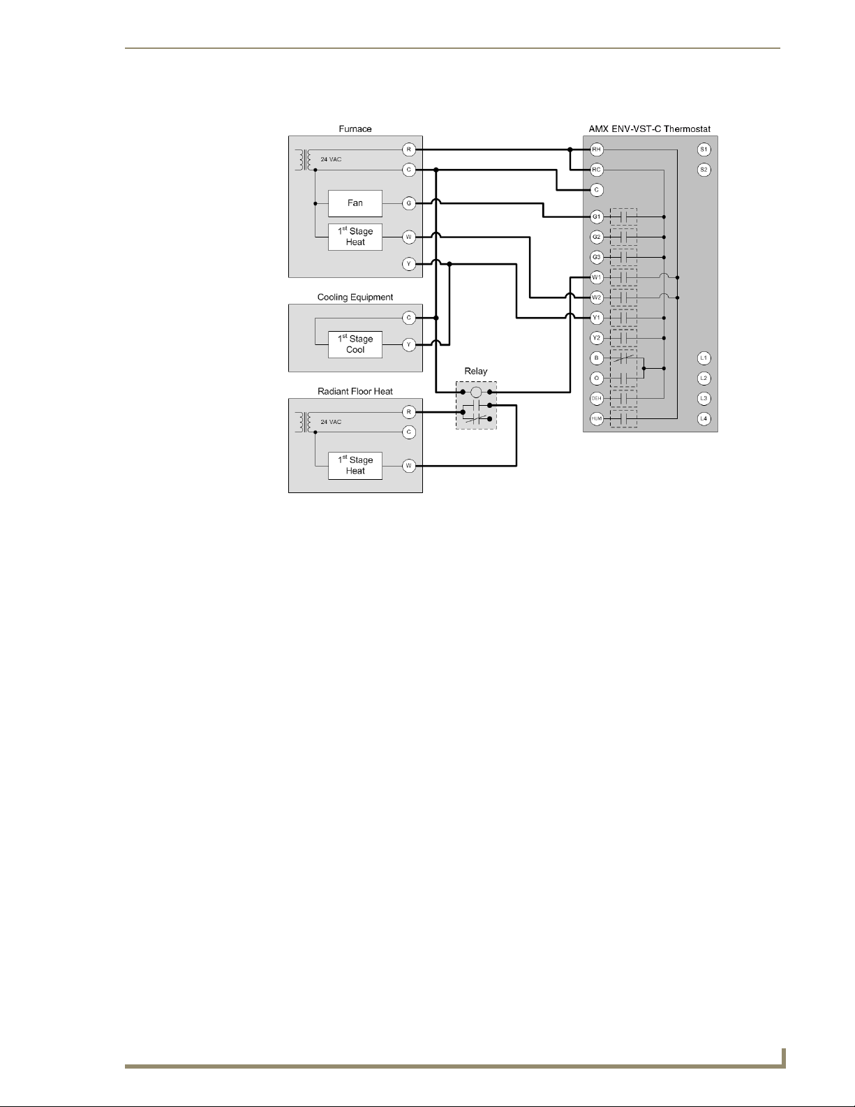
First Stage Radiant Floor Heat, Second Stage Furnace with Single Stage Cooling
FIG. 9 First Stage Radiant Floor Heat, Second Stage Furnace with Single Stage Cooling wiring
iewStat Color Communicating Thermostat
13
Page 20
Installation and Wiring
Installing a Remote Sensor
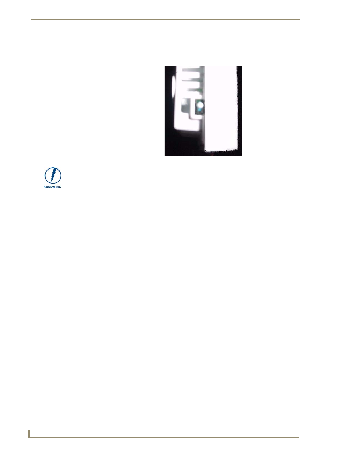
The ViewStat Color Communicating Thermostat has an onboard temperature sensor that can read and
report the temperature at the location of the unit (see FIG. 10).
Do not paint or tape over the onboard temperature sensor. Doing so can cause the sensor to work
improperly.
Onboard
temperature
sensor
FIG. 10 Onboard temperature sensor
You can install an additional remote sensor to get a temperature reading from a location away from the
thermostat. If you install a remote sensor, you can use the temperature reading as the main reported
temperature, or you can use the temperature reading with the reading from the onboard sensor to report
an average temperature for the zone. The ViewStat Color Communicating Thermostat supports only one
installed remote sensor. The sensor connects to the S1 or S2 terminal on the ViewStat. See the
Communication and Equipment Terminal Wiring Definitions section on page 7 for more information on
the terminals on the thermostat.
You can install the indoor/outdoor temperature sensor that ships with the unit, or you can install an
indoor flush mount sensor (FG2050-21), available for purchase separately. You can use either sensor
with the thermostat, but not both at the same time, as the thermostat supports only one external sensor.
Refer to the ViewStat Color Communicating Thermostat User Guide for information on enabling or
disabling each sensor.
Installing the Indoor/Outdoor Remote Sensor
FIG. 11 displays the indoor/outdoor remote sensor. You can install this sensor outdoors for a reading of
the outdoor temperature that the sensor reports back to the thermostat. You can also install this sensor
indoors for an extra indoor temperature reading. You can use the indoor reading with the reading from
the on-board temperature sensor on the thermostat to report an average indoor temperature.
14
ViewStat Color Communicating Thermostat
Page 21

Installation and Wiring
V
The sensor has a 1" head that protrudes from the wall and a connected wire that plugs into a port on the
thermostat. You can use a maximum of 300 ft (91.44 m) of wire for connecting the indoor/outdoor
remote sensor to the thermostat.
Sensor head
Connecting wires
FIG. 11 Indoor/Outdoor Remote Sensor
Follow these steps to install the indoor/outdoor remote sensor:
1. Drill a 1/4" hole into the surface where you want to install the sensor.
2. Fish the cable that connects to the sensor through the 1/4" hole in the wall until the edge of the
sensor, where the cord meets the sensor, is flush against the wall.
3. Apply caulk, drywall putty, insulation, or any other appropriate sealant to the hole in the wall
around the sensor to seal the hole.
4. Attach the connecting wires from the sensor to the S1 and S2 terminals on the thermostat (see
FIG. 12). It does not matter which wire you connect to either terminal.
Sensor wires
FIG. 12 Indoor/outdoor sensor wiring to S1 and S2 terminals
iewStat Color Communicating Thermostat
15
Page 22
Installation and Wiring
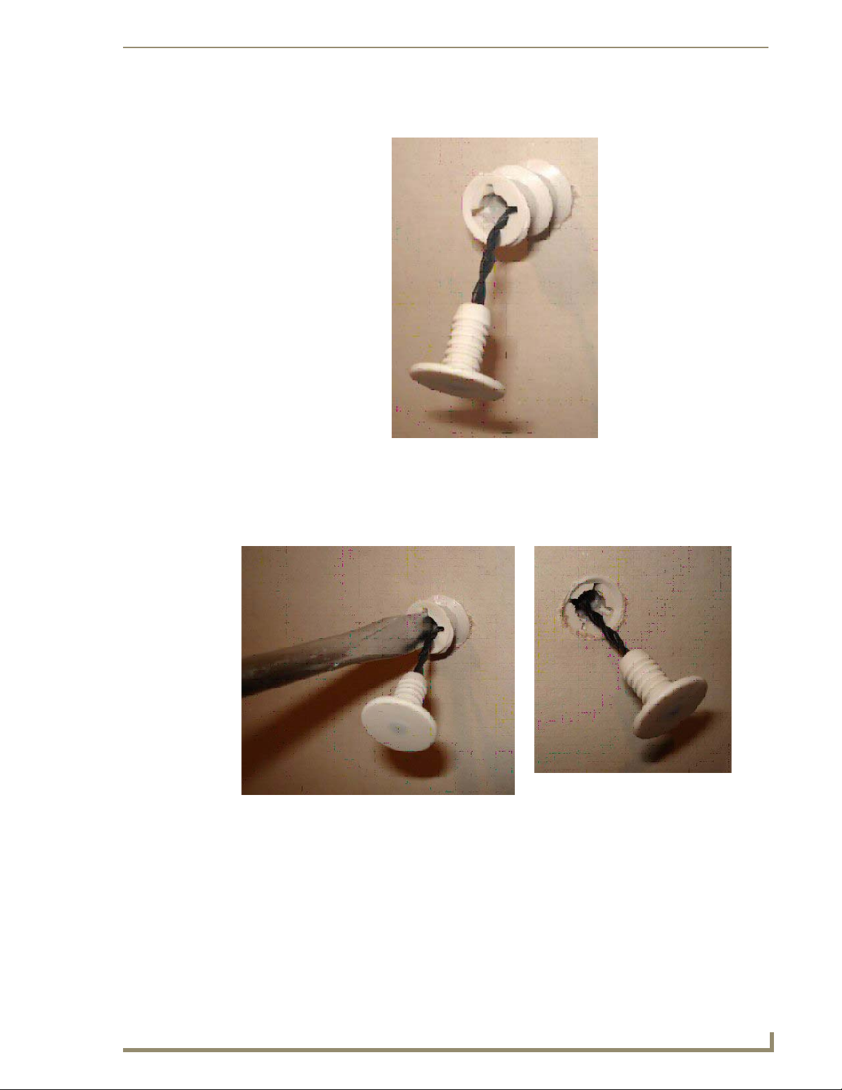
Installing the Indoor Flush Mount Sensor
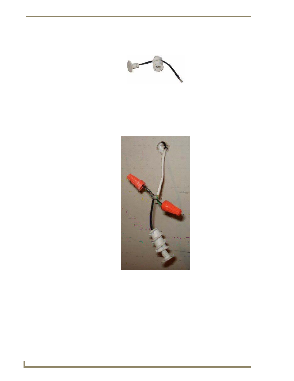
FIG. 13 displays the two pieces of the indoor flush mount sensor. The two pieces are the sensor body
with the connected wire and the threaded outer case of the sensor.
Follow these steps to install the indoor flush mount sensor:
1. Drill a ½" hole into the drywall where you want to install the sensor.
2. Fish the cable that connects to the sensor from behind the drywall and out through the ½" hole so
3. Feed the sensor wire through the center of the threaded outer case of the sensor and connect it to the
FIG. 13 Indoor Flush Mount Sensor
that 6" - 12" of the cable hangs through the hole.
cable that is hanging through the hole in the wall as shown in FIG. 14.
16
FIG. 14 Sensor wire connected to cable
ViewStat Color Communicating Thermostat
Page 23
Installation and Wiring
V
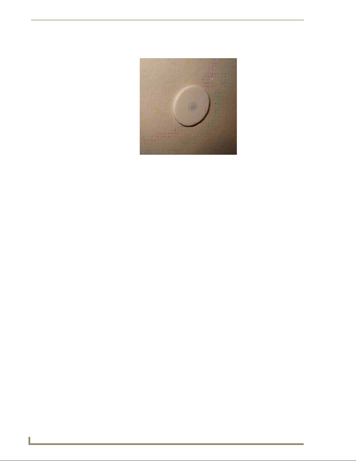
4. Carefully feed the wires and wire-nuts through the ½" hole and into the wall. Use your hands to
lightly screw the threaded outer case into the hole in the wall as shown in FIG. 15.
FIG. 15 Outer case screwed into wall
5. Use a screwdriver to screw the threaded outer case of the sensor the rest of the way into the ½" hole
in the drywall. Be careful to not pinch the wire while you are screwing in the case. Screw the case
into the wall until the front surface of the case is inserted just past the surface of the drywall (see
FIG. 16).
FIG. 16 Screwing the outer case into the wall
iewStat Color Communicating Thermostat
17
Page 24
Installation and Wiring
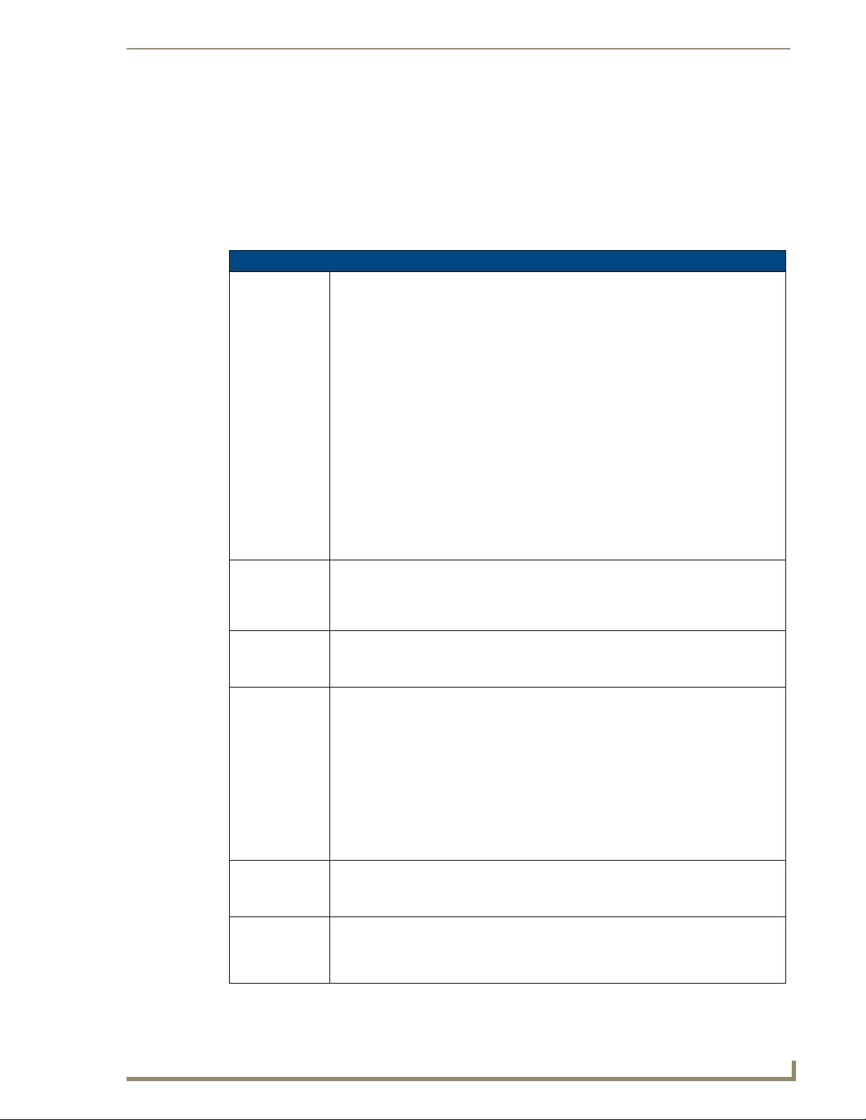
6. Use your thumb to carefully push the sensor body into the threaded outer case until the face of the
7. Attach the connecting wires from the sensor to the S1 and S2 terminals on the thermostat (see
sensor body is flat against the drywall (see FIG. 17).
FIG. 17 Sensor installed in wall
FIG. 12). It does not matter which wire you connect to either terminal.
18
ViewStat Color Communicating Thermostat
Page 25
V
Programming
The ViewStat Color Communicating Thermostat supports the commands listed below. All commands
supported by the thermostat are common and expected from all AxLink devices.
Send Commands
Send Commands
CLOCK
Sets the
thermostat’s date
and time.
RESET
Cycles power to
the device.
SLEEP
Activates screen
saver mode.
VER
Requests
firmware version.
WAKE
Activates the
display.
ZAP!
Resets thermostat
to factory default
configuration.
Programming
Includes the current date and time in 24-hour format. Uses the current date and time to
compute the current day of the week.
Syntax:
SEND_COMMAND ’CLOCK <mm-dd-yy> <hh:mm:ss>’
Variable:
dd-mm-yy = 8 bytes with values separated by the character ’-’
dd = day with values 01-31
mm = month with values 01-12
yy = year with values 00-99
hh:mm:ss = 8 bytes with values separated by the character ’:’
hh = hours with values 00-23
mm = minutes with values 00-59
ss = seconds with values 00-59
Examples:
SEND_COMMAND ’CLOCK 03-28-07 05:30:07’
Sets the date and time to March 28, 2007 5:30:07 AM.
Cycles power to the device so the user does not have to be physically present to reboot
the device.
Syntax:
SEND_COMMAND ’RESET’
Sets the display to inactive brightness.
Syntax:
SEND_COMMAND ’SLEEP’
Sent by the Master to request the thermostat’s firmware version. The thermostat responds
to the Master with a command in the form of ’vX.XX’ (e.g. v1.02)
Syntax:
SEND_COMMAND ’VER’
Example:
SEND_COMMAND ’VER’
Master requests version number of the device.
SEND_COMMAND ’v1.02’
Device response with version 1.02.
Sets the display to active brightness.
Syntax:
SEND_COMMAND ’WAKE’
Restores the unit to its factory defaults, but does not change its AxLink address.
Syntax:
SEND_COMMAND ’ZAP!’
iewStat Color Communicating Thermostat
19
Page 26

Programming
The Color ViewStat thermostat does not support string messages. A command message either
does not have a response, or another command responds to it, but it never receives a string
response.
Color ViewStat Thermostat Commands
This section lists commands that are specific to the Color ViewStat Thermostat.
5-Day Forecast Commands
The 5-Day Forecast commands, FH, FL, and FK, give the 5-Day Forecast sent in three separate
messages, one for each of the following:
Expected high temperatures, FH
Expected low temperatures, FL
Expected weather conditions keywords, FK
The data always starts with the current day's information. Temperatures are be reported in the same scale
as set on the thermostat, in Fahrenheit or Celsius. The Weather Condition Keywords have been shortened
to accommodate for the AxLink 64 character message limit. The Weather Condition Keywords include
the following:
BLZ for Blizzard
BLSN for Blowing Snow
CLEAR
CLDY for Cloudy
DRZL for Drizzle
FAIR
FOG
FZDRZL for Freezing Drizzle
FZRAIN for Freezing Rain
HAZE
HUMID
ICE
MCLDY for Mostly Cloudy
MSUN for Mostly Sunny
PCLDY for Partly Cloudy
RAIN
RAINSW for Rain Showers
RAINSN for Rain Snow Mix
SLEET
SMOKE
SNOW
SNOWFL for Snow Flurries
SNOWSW for Snow Showers
SUN for Sunny
20
ViewStat Color Communicating Thermostat
Page 27

V
TSTORM for Thunder Storms
UNK for Unknown
VCOLD for Very Cold
WINDY
5-Day Forecast Commands
FH
Forecasted 5-day
high temperatures
FL
Forecasted 5-day
low temperature
FK
Forecasted 5-day
weather
conditions
Syntax:
FH <HT1> <HT2> <HT3> <HT4> <HT5>
Variable:
HTx = The high temperature in degrees expected for day x, where x = 1 is the current
day, 2 is the next day, etc.
Example:
SEND_COMMAND ’FH 78 82 85 84 85’
Five-day high temperatures.
Syntax:
FL <LT1> <LT2> <LT3> <LT4> <LT5>
Variable:
LTx = The low temperature in degrees expected for day x, where x = 1 is the current day,
2 is the next day, etc.
Example:
SEND_COMMAND ’FL 37 39 40 41 38’
Five-day low temperatures.
Syntax:
FK <KY1> <KY2> <KY3> <KY4> <KY5>
Variable:
KYx = The weather condition expected for day x, where x = 1 is the current day, 2 is the
next day, etc.
Example:
SEND_COMMAND ’FK SNOW ICE SNOWSW SNOWFL SLEET’
Five-day weather condition forecast.
Programming
iewStat Color Communicating Thermostat
21
Page 28

Programming
AxLink Commands
This section contains AxLink commands that are specific to the ViewStat Color Thermostat. For
additional AxLink programming commands specific to a particular AxLink device, consult the manual
for the AxLink device you are using.
AxLink Commands
BK
Sets the backlight
timeout value and
active and
inactive
brightness.
CD
Retrieves and
sets the security
code
configuration.
CF
Displays the
current forecast.
Syntax:
BK [T<SEC>] [A<ABVAL>] [I<IBVAL>]
Variable:
SEC = An integer with a value between 10 and 300 in values evenly divisible by 10.
ABVAL = A single character with a value of L, M, or H, where L=Low, M=Medium, and
H=High
IBVAL = A single character with a value of D or O, where D=Dim and O=Off
Example:
SEND_COMMAND ’BK T20 IO’
Sets the timeout to 20 seconds and Inactive Brightness to OFF.
SEND_COMMAND ’BK T10 AL’
Sets the timeout to 10 seconds and Active Brightness to ON.
Syntax:
CD <Code>
Variable:
Code = A 4-character integer.
Example:
SEND_COMMAND ’CD 1988’
Changes the security code to 1988.
Syntax:
CF F<Temp> W<Direct> S<Speed> H<HRead> D<DewPT>
Variable:
Temp = The wind chill or heat index that denotes what the temperature feels like outside.
The temperature is reported in the same scale as set on the thermostat: Fahrenheit (F)
or Celsius (C).
Direct = A single character noting the wind direction (N, S, E, or W).
Speed = The wind speed in either miles per hour (mph) or kilometers per hour (kph),
depending on the temperature scale.
HRead = The current percent humidity reading with a range of 0 to 100%.
DewPT = The current dew point temperature reported in the same scale as set on the
thermostat: F or C.
Example:
SEND_COMMAND ’CF F40 WN S25 H35 D55’
Reports the forecast as Wind Chill: 40F, Wind Direction: North, Wind Speed: 25 mph,
Humidity: 35%, Dew Point: 55F.
22
ViewStat Color Communicating Thermostat
Page 29

V
AxLink Commands (Cont.)
FM
Sets or changes
the thermostat’s
scale, date, or
time format.
LK
Configures button
lockout settings
for temperature,
mode, and fan
speed
Syntax:
FM [S<TSCL>] [D<DFMT>] [T<TFMT>]
Variable:
TSCL = A single character: F for Fahrenheit or C for Celsius
DFMT = A single character: D for DD/MM/YYYY, M for MM/DD/YYYY, or
Y for YYYY/MM/DD
TFMT = A single character: 1 for 12-hour or 2 for 24-hour clock.
Example:
SEND_COMMAND ’FM SF’
Sets the thermostat scale to Fahrenheit.
SEND_COMMAND ’FM DD T2’
Sets the date format to DD/MM/YYYY and the time format to 24-hour clock.
You can completely block anyone from using the buttons on the front of the unit to change
the hold temperature, mode, or fan speed changes, or restrict them by time. You can also
restrict hold temperature changes by range. If you configure a time limit, the hold
temperature, mode, or fan speed reverts to the original settings after the set time expires.
If you configure a range, the hold temperature may not be set higher or lower than the set
temperature +/- the range.
Syntax:
LK [MR<State>] [MT<Time>] [FR<State>] [FT<Time>] [TR<State>]
[TT<Time>] [RR<Range>]
Variable:
State = An integer value, 0 for disable and 1 for enable.
Time = An integer representing the number of minutes a change is enabled.
Range = An integer representing the number of degrees a temperature is allowed to be
changed. Degrees are in the same scale as set on the thermostat.
MR = Mode Restriction, State=1: disable all changes to Mode. State=0: restrictions to
Mode determined by MT, Mode Time Restriction.
MT = Time Restriction placed on changes to TSTAT Mode
FR = Fan Speed Restriction, State=1: disable all changes to Fan Speed. State=0:
restrictions to Fan Speed determined by FT, Fan Speed Time Restriction.
FT = Time Restriction placed on changes to Fan Speed
TR = Temperature Restriction, State=1: disable all changes to Temperature Heat and
Cool Setpoints. State=0: restrictions to Temperature Heat and Cool Setpoints
determined by TT, Temperature Time Restriction, and TR, Temperature Range
Restriction.
TT = Time Restriction placed on changes to Temperature
RR = Range Restriction placed on changes to Temperature
Examples:
SEND_COMMAND ’LK MR1 TR3’
Configures the lockout to completely block changes to Mode and restrict changes to the
temperature setting to ±3 degrees.
SEND_COMMAND ’LK TT90 FT90’
Configures the lockout to allow changes to the temperature and fan speed for 90 minutes
before reverting to the original settings.
Programming
iewStat Color Communicating Thermostat
23
Page 30

Programming
AxLink Commands (Cont.)
MD
Sets or changes
the thermostat’s
mode.
PG
Sets the 7-day
program.
Supported thermostat modes include Program, Vacation, or Hold Temperature. Vacation
mode includes the heat, cool, humidify, and dehumidify setpoints to maintain, and the
duration of the Vacation mode in days and hours. Hold Temperature mode includes the
specified heat and cool setpoints to maintain. Temperatures in the message are in the
same temperature scale as set on the thermostat: F or C.
Syntax:
MD M<Mode> [H<HSP> C<CSP> U<HUSP> D<DUSP> Y<Days> R<Hours>]
Variable:
Mode = P, V, H, or O for Program, Vacation, Hold, or Off. If you are setting Hold mode,
you must establish settings for HSP and CSP. If you are setting Vacation mode, you
must establish settings for all variables.
HSP = The heat setpoint to maintain in degrees in the scale set on the thermostat.
CSP = The cool setpoint to maintain in degrees in the scale set on the thermostat.
HUSP = The humidify setpoint to maintain in % RH.
DUSP = The dehumidify setpoint to maintain in % RH.
Days = The number of days to maintain Vacation mode.
Hours = The number of hours to maintain Vacation mode.
Examples:
SEND_COMMAND ’MD MP’
Sets the mode to Program.
SEND_COMMAND ’MD MV H60 C85 U40 D65 Y3 R6’
Sets the mode to Vacation with settings of heat setpoint: 60F, cool setpoint: 85F, humidify
setpoint: 40%, and dehumidify setpoint: 65% for 3 days and 6 hours.
SEND_COMMAND ’MD MH H72 C75’
Sets the mode to Hold with settings of heat setpoint: 72F and cool setpoint: 75F.
The Master sends the ?PG command to request the value of a program configuration
setpoint.
Syntax:
PG D<Day> SP<DaySP> HT<HeatSP> C<CoolSP> HM<HSP> DM<DSP>
Variable:
Day = Day of the week. An integer with a value of 0-6 where 0 = Sunday, 1 = Monday,
etc.
DaySP = Time of day for a setpoint. An integer with a value of 1-4 where 1 = Wake,
2 = Leave, 3 = Return, and 4 = Sleep.
HeatSP = Heat setpoint for this day and setpoint. An integer with a value in degrees
reported in the set temperature scale, F or C.
CoolSP = Cool setpoint for this day and setpoint. An integer with a value in degrees
reported in the set temperature scale, F or C.
HSP = Humidify setpoint for this day and setpoint with a range of 0-100.
DSP = Dehumidify setpoint for this day and setpoint with a range of 0-100.
Example:
SEND_COMMAND ’PG D0 SP3 HT68 C72 HM30 DM50’
Sunday night setpoint, heat setpoint: 68F, cool setpoint: 72F, humidify setpoint: 30% RH,
dehumidify setpoint: 50% RH.
SEND_COMMAND ’?PG DM4 SP1’
The Master requesting the program configuration for the Thursday Wake setpoint.
24
ViewStat Color Communicating Thermostat
Page 31

V
AxLink Commands (Cont.)
?SERIAL
Retrieves the
16-byte serial
number set on the
thermostat.
SP
Sets or changes
the humidify and
dehumidify set
points.
ST
Queries for the
thermostat system
configuration.
The Master sends the ?SERIAL command to request the thermostat’s serial number.
Syntax:
?SERIAL
Example:
SEND_COMMAND ’?SERIAL’
The Master requesting the thermostat’s serial number.
SEND_COMMAND ’SERIAL 1234567890123456’
The thermostat returns the serial number 1234567890123456.
Syntax:
SP H<HSP> D<DSP>
Variable:
HSP = The new humidify setpoint with a range of 0 to 100.
DSP = The new dehumidify setpoint with a range of 0 to 100.
Example:
SEND_COMMAND ’SP H75 D20’
Sets the humidify setpoint to 75% and the dehumidify setpoint to 20% RH.
When received the thermostat reports its configured humidify and dehumidify set points,
thermostat mode, and temperature scale.
Syntax:
SEND_COMMAND ’ST’
Programming
AxLink Channels
Each AXLink device contains 255 channels numbered 1-255. The AxLink Channels for the thermostat
are defined in the table below. The Type column indicates who initiates the channel change. The Master
directs the thermostat to change its state through channels with type CMD. The thermostat informs the
Master of state changes through channels with type FDBK. Some channels can be used for both CMD
and FDBK.
AxLink Channels
Channel Type Function Description
1-138 Not Used
139 CMD Weather Alert A Weather Alert is active while the channel is
140 CMD Increment Cool Set Point Increases the cool set point by one step per
141 CMD Decrement Cool Set Point Decreases the cool set point by one step per
142 Not Used
143 CMD Increment Heat Set Point Increases the heat set point by one step per
144 CMD Decrement Heat Set Point Decreases the heat set point by one step per
145-147 Not Used
148 CMD Increment Humidify Set
Point
ON. To clear an active Weather Alert set the
channel to OFF.
pulse while the channel is active (ON).
pulse while the channel is active (ON).
pulse while the channel is active (ON).
pulse while the channel is active (ON).
Continue to increment the humidify set point
while the channel is active, ON, as if the
increment button were being pushed.
iewStat Color Communicating Thermostat
25
Page 32
Programming
AxLink Channels (Cont.)
Channel Type Function Description
149 CMD Decrement Humidify Set
Point
150 CMD Increment Dehumidify Set
Point
151 CMD Decrement Dehumidify Set
Point
152-208 Not Used
209 CMD Fan Speed Low Set the Fan Speed to Low when the channel
210 CMD Fan Speed Medium Set the Fan Speed to Medium when the
211 CMD Fan Speed High Set the Fan Speed to High when the channel
212 CMD/FDBK Lock Out State Source ? Master: Set the Lock Out Mode
213 Not Used
214 CMD Fan State On Set the Fan state to On while the channel is
215 CMD Fan State Auto Set the Fan state to Auto while the channel
216 FDBK Fan Status Feedback, Fan Status changed, Fan status
217-218 Not Used
219 CMD HVAC State Auto Set the HVAC state to auto while the channel
220 CMD HVAC State Cool Set the HVAC state to cool while the channel
221 CMD HVAC State Heat Set the HVAC state to heat while the channel
222 CMD HVAC State Off Set the HVAC state to off while the channel
223 CMD HVAC State Emergency
Heat
224 FDBK HVAC Cool Status Feedback, HVAC Cool Status changed
225 FDBK HVAC Heat Status Feedback, HVAC Heat Status changed
226 Not Used
Continue to decrement the humidify set point
while the channel is active, ON, as if the
decrement button were being pushed.
Continue to increment the dehumidify set
point while the channel is active, ON, as if
the increment button were being pushed.
Continue to decrement the dehumidify set
point while the channel is active, ON, as if
the decrement button were being pushed.
is ON.
channel is ON.
is ON.
: TStat: FDBK, Lock Out Mode
Changed
Channel ON: Lock Out Mode Enabled,
Channel OFF: Lock Out Mode Disabled.
ON.
is ON.
is controlled by the TSTAT.
Channel ON: Fan is On,
Channel OFF: Fan is Off.
is active, ON.
is active, ON.
is active, ON.
is active, ON.
Set the HVAC state to Emergency Heat
while the channel is active, ON.
Channel ON: A/C is On,
Channel OFF: A/C is Off.
Channel ON: Heat is On,
Channel OFF: Heat is Off.
26
ViewStat Color Communicating Thermostat
Page 33
Programming
V
AxLink Channels (Cont.)
Channel Type Function Description
227 FDBK HVAC Emergency Heat
Status
228 CMD Humidify State Auto Set the humidify state to auto while the
229 CMD Humidify State Dehumidify Set the humidify state to dehumidify while
230 CMD Humidify State Humidify Set the humidify state to humidify while the
231 CMD Humidify State Off Set the humidify state to off while the
232 FDBK Dehumidify Status Feedback, Dehumidify Status changed
233 FDBK Humidify Status Feedback, Humidify Status changed
234-255 Not Used
Feedback, HVAC Emergency Heat Status
changed
Channel ON: Emergency Heat is On,
Channel OFF: Emergency Heat is Off.
channel is active, ON.
the channel is active, ON.
channel is active, ON.
channel is active, ON.
Channel ON: Dehumidifier is On,
Channel OFF: Dehumidifier is Off.
Channel ON: Humidifier is On,
Channel OFF: Humidifier is Off.
AxLink Levels
Each AXLink device contains 8 levels numbered 1-8. Levels are a means of applying a value to a
physical element on the device.
When a device is online for the first time, the Master assumes the device is at the default level status with
all levels set to 0. However, the thermostat may not be in this default state and needs to tell the Master
the value of any non-zero level. After a 'LEVON' command is received from the Master, the thermostat
sends a level update for any levels that are non-zero.
If the level represents a temperature, then the level value is equivalent to the degree reading plus 120.
The temperature reading is reported in the set temperature scale, F or C. For example, if the temperature
scale is F and the temperature reading is -10 then the level value would be 110. If the temperature scale
is C and the temperature reading is 25 then the level value would be 145.
If the level represents a humidity reading, then the level value is equivalent to the humidity reading. The
valid range of a level associated with a humidity reading is 0-100. Therefore, levels with values between
0-100 are valid representing humidity readings of 0% to 100%, and level values from 101-255 are
invalid.
In the Level table below, Type column denotes who initiates the level change. The Master directs the
thermostat to change its state through Level of type CMD. The thermostat informs the Master of state
changes through Levels of type FDBK.
iewStat Color Communicating Thermostat
27
Page 34
Programming
AxLink Levels
Level Type Function Description
1 FDBK Indoor Temperature The current indoor temperature reading from
the thermostat sensors. Level value is
equivalent to the degree reading plus 120.
2 FDBK Indoor Humidity The current indoor humidity reading from the
thermostat sensors. Valid level values are
0-100% relative humidity.
3 FDBK Current Heat Set Point The current heat set point from the
thermostat sensors. Level value is
equivalent to the degree reading plus 120.
4 FDBK Current Cool Set Point The current cool set point from the
thermostat sensors. Level value is
equivalent to the degree reading plus 120.
5 CMD Outdoor Temperature The current outdoor temperature reading
from the Master. Level value is equivalent to
the degree reading plus 120.
6 CMD Barometric Pressure The current outdoor barometric pressure
reading from the Master. Value is in inches or
centimeters, depending on temperature
scale.
7 CMD High Forecast Temperature The current high temperature forecast from
the Master. Level value is equivalent to the
degree reading plus 120.
8 CMD Low Forecast Temperature The current low temperature forecast from
the Master. Level value is equivalent to the
degree reading plus 120.
Weather Duet Module
A weather Duet Module communicates with the AMX i!-Weather internet service to gather the current
forecast. The Duet Module retrieves current weather conditions and forecasts from the AMX i!-Weather
service and displays the current weather information on the thermostat.
With each thermostat, you receive a certificate for a three-year subscription to the i!-Weather service.
While you receive one subscription service per thermostat, you only need to use one subscription per
Master, even if you have multiple thermostats connected to the Master.
Subscriptions are not stackable. If you are using multiple thermostats on a single Master, you
cannot use the subscription on one of the additional thermostats once the subscription on the first
thermostat expires.
Follow these steps to download, install, and configure the Weather Duet Module.
1. Open a web browser, and access the InConcert
on the main page.
2. Locate the i!-Weather Duet Module and download the AMX_iWeather_Comm_dr1_0_0.jar file
(FIG. 18).
®
section on www.amx.com, located under Partners
28
ViewStat Color Communicating Thermostat
Page 35

Programming
V
Duet Module
.jar file
FIG. 18 InConcert window
3. Copy the AMX_iWeather_Comm_dr1_0_0.jar file into the same project folder as the
AMX_ENV-VST-C_Comm_dr1_0_0.jar file on the NetLinx Master.
4. Add the AMX_iWeather_Comm_dr1_0_0.jar file name to the thermostat’s project files in the
NetLinx Studio Workspace, so it will be downloaded with the thermostat files.
5. Define virtual device and real (IP) device numbers for the Weather module, and place a
DEFINE_MODULE statement for the module into the thermostat’s NetLinx program. FIG. 19
displays sample code using the DEFINE_MODULE statement. (For more information, consult the
NetLinx Programming Language Reference Guide.) These statements appear as commented lines in
the thermostat’s Main.axs file.
FIG. 19 Define Module code
The Weather module starts, and the thermostat module automatically finds and uses it. No additional
NetLinx code is required.
iewStat Color Communicating Thermostat
29
Page 36
Programming
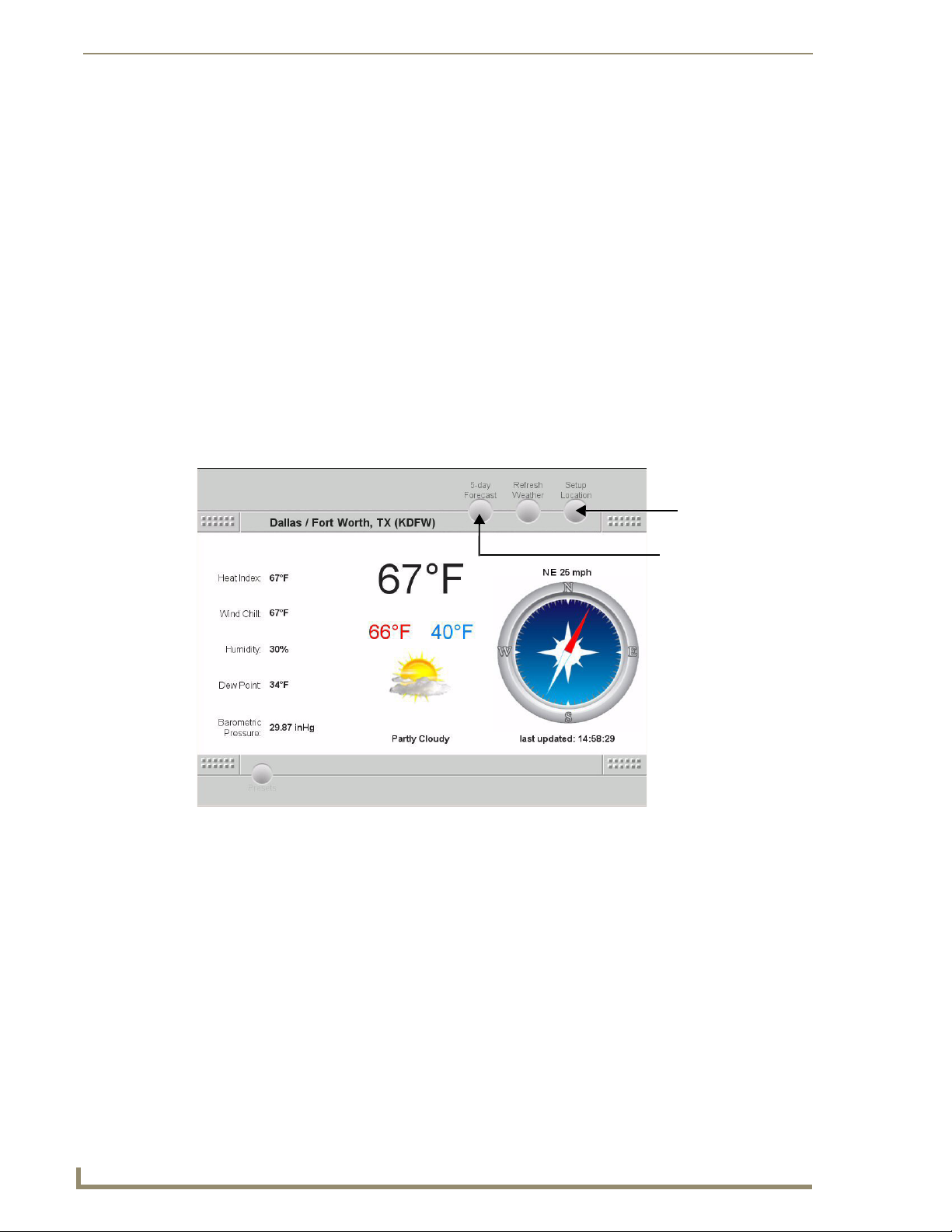
i!-Weather Setup Pages
The i!-Weather application enables you to retrieve and display current weather with 5-day forecasting
from AMX’s weather provider on your touch panel. The Main page (FIG. 20) displays the following
current weather content:
City name for current weather
Current Heat Index
Current Temperature
Current Wind Chill
Wind Direction
Current Humidity
Wind Speed
Current Dew Point
Current Conditions
Current Barometric Pressure
Setup Location
FIG. 20 i!-Weather Main page
5-day Forecast
30
ViewStat Color Communicating Thermostat
Page 37
V
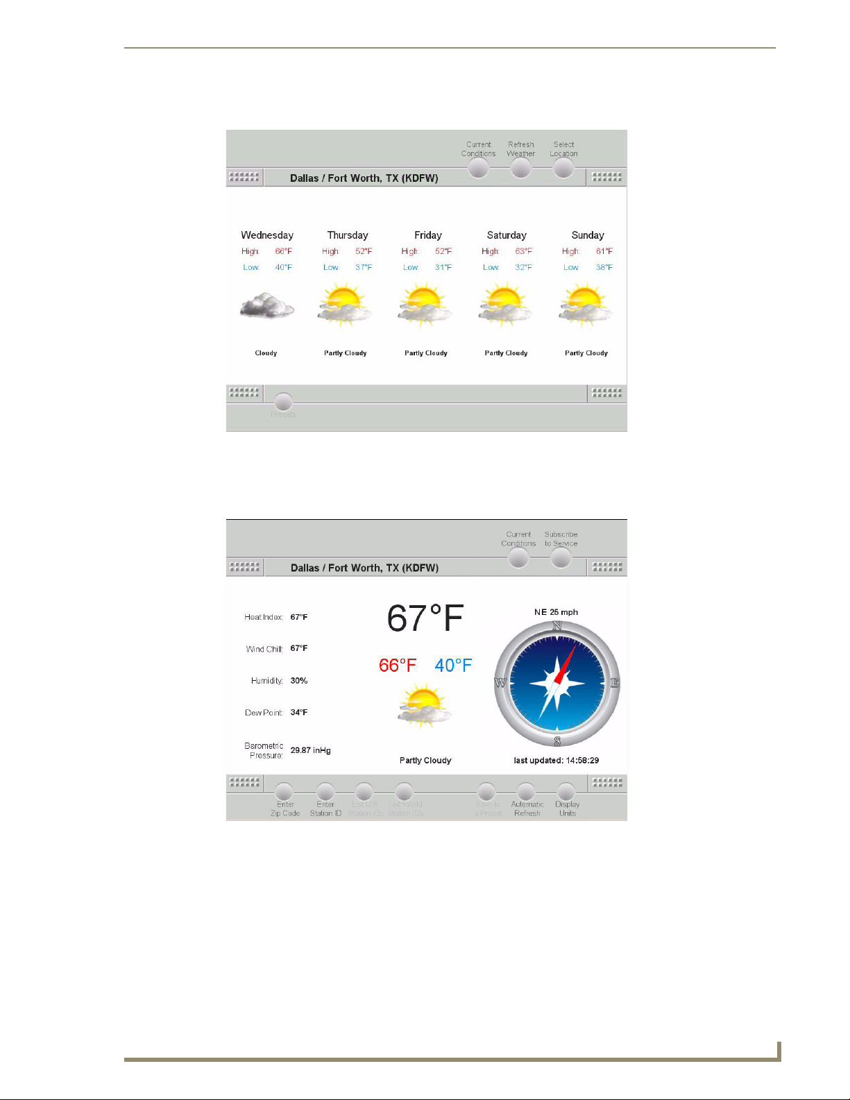
You can access the 5-Day Forecast screen by pressing 5-day Forecast on the Main page.
FIG. 21 5-Day Forecast screen
Programming
You can return to the Main page by pressing Current Conditions.
You can adjust your location, station ID, and unit settings by pressing Setup Location on the Main page.
FIG. 22 Setup Location screen
iewStat Color Communicating Thermostat
31
Page 38

Programming
Entering Location by Zip Code
To enter a location by Zip code:
1. Press Setup Location on the Main page to navigate to the Select Location page (FIG. 22).
2. Select Enter Zip Code. A pop-up screen opens.
3. Enter the 5-digit zip code.
4. Press Done.
Pressing Done returns you to the Select Location page and displays the corresponding city at the top of
the page.
Entering Location by Station ID
To enter a location by Station ID:
1. Press Setup Location on the Main page to navigate to the Select Location page (FIG. 22).
2. Select Enter Station ID. A pop-up screen opens.
3. Enter the 4-character Station ID.
4. Press Done.
Pressing Done returns you to the Select Location page and displays the corresponding city at the top of
the screen.
Changing Temperature Units
To change temperature units:
1. Press Setup Location on the Main page to navigate to the Select Location page (FIG. 22).
2. Select Display Units. The Unit Selection menu opens with a series of options.
3. Select Fahrenheit or Celsius.
Next time a weather refresh occurs the units will be updated.
Changing Wind Speed Units
To change wind speed units:
1. Press Setup Location on the Main page to navigate to the Select Location page (FIG. 22).
2. Select Display Units. The Unit Selection menu opens with a series of options.
3. Select Miles per hour (mph), Kilometers per hour (kph), or Knots.
Next time a weather refresh occurs the units will be updated.
Changing Pressure Units
To change pressure units:
1. Press Setup Location on the Main page to navigate to the Select Location page (FIG. 22).
2. Select Display Units. The Unit Selection menu opens with a series of options.
3. Select Inches of Mercury (inHg), Millimeters of Mercury (mmHg), or Millibars.
Next time a weather refresh occurs the units will be updated.
32
ViewStat Color Communicating Thermostat
Page 39

Programming
V
Auto Refresh Interval Select
To select an auto refresh interval:
1. Press Setup Location on the Main page to navigate to the Select Location page (FIG. 22).
2. Select Automatic Refresh. The Refresh Interval menu opens with a series of options.
3. Select desired auto refresh time interval.
If you select Off, the weather can only be refreshed manually.
Auto Refresh refreshes weather data for the current weather location.
iewStat Color Communicating Thermostat
33
Page 40

Programming
34
ViewStat Color Communicating Thermostat
Page 41

Programming
iewStat Color Communicating Thermostat
35
Page 42

It’s Your World - Take Control™
3000 RESEARCH DRIVE, RICHARDSON, TX 75082 USA • 800.222.0193 • 469.624.8000 • 469-624-7153 fax • 800.932.6993 technical support • www.amx.com
2008 AMX. All rights reserved. AMX and the AMX logo are registered trademarks of AMX. AMX reserves the right to alter specifications without notice at any time.
©
12/08
 Loading...