

Page 1
DXLink™ Multi-Format Decor Style Wallplate Transmitter (US)
Both available
in white (WH)
and black (BL)
Enova DGX 16
Twisted pair cable
HDMI cable
DXLink
Source device
DXLink
Input Board
Multi-Format
Wallplate TX
(Front) (Rear)
DIP switch
EU flush mount inside wall
US flush mount inside wall
UK flush mount inside wall
UK surface mount exterior wall or
Wallplate TX
Use screw holes indicated with “X”s below:
mounting bracket
Overview
The DXLink Multi-Format Wallplate TX and DXLink Multi-Format Decor Style Wallplate
TX are used in conjunction with switchers that support DXLink Technology for
transmission of HDMI or analog video over twisted pair cable. Both Transmitters are
compatible with the DXLink HDMI RX and support InstaGate Pro® Technology. The
Instruction Manual – DXLink Twisted Pair Transmitters /Receiver contains complete
documentation (including full specifications and supported input and output
resolutions); for details, see www.amx.com.
Quick Start Guide
DXLink™ Multi-Format Wallplate Transmitter and
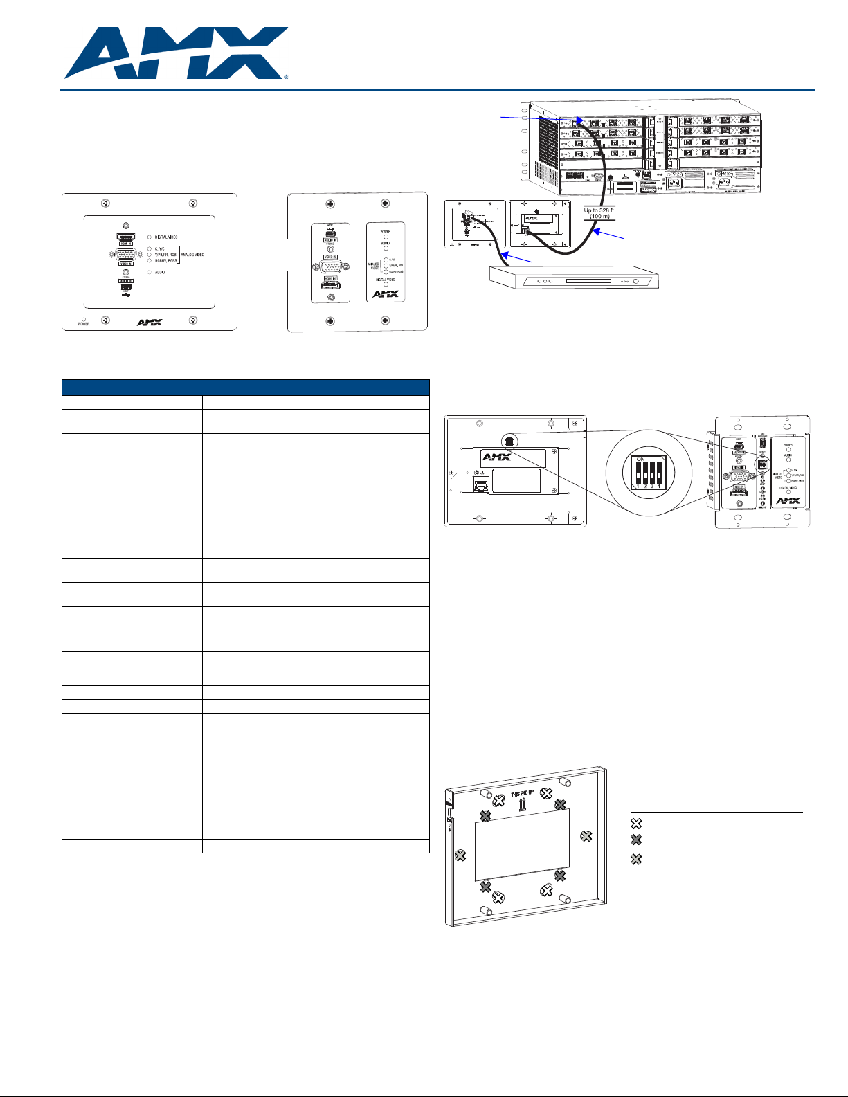
FIG. 2 Wallplate TX (front and rear) used with DXLink input board in an Enova DGX 16
FIG. 1
Wallplate TX – FG1010-320-WH (left) and Decor TX– FG1010-325-WH (right)
General Specifications
General Specifications
Approvals CE, cUL, FCC Class A, RoHS
Power Consumption,
Enova DXLink Supplied (max.)
DXLink Power
Note: For Wallplate use in an
Enova DGX system, use the
Enova DGX Configuration Tool
located at www.amx.com/enova
to determine power requirements of a configuration and
whether any DXLink units should
be powered with local power.
Thermal Dissipation,
Enova DXLink Supplied (max.)
Operational Temperature
Storage Temperature
Operational Humidity
Storage Humidity
Dimensions:
• Wallplate TX
• Decor Wallplate TX
Weight / Shipping Weight
• Wallplate TX
• Decor Wallplate TX
MTBF 381,000 hours
Compatible Formats HDMI (HDCP), DVI (DVI requires conversion cable)
Analog Signal RGBHV, RGBS, RGB, Y/Pb/Pr, Y/c, composite
Supported Twisted Pair Cable
Types
Supported Twisted Pair Cable
Length – Up to 328 ft. (100 m)
Compatible Products Enova DGX 8/16/32; some Enova DVX Solutions
* “Common building” is defined as: Where the walls of the structure(s) are physically
connected and the structure(s) share a single ground reference.
7 W
• Power must be supplied by a DXLink Power sourcing
device such as an Enova DGX 8/16/32 or
compatible Enova DVX (3155HD or 2155HD) or
PDXL-2 (FG1090-170) or PS-POE-AT-TC
(FG423-84). AMX does not support the use of any
other PoE injectors as these may potentially damage
the DXLink equipment.
• To use PDXL-2 or PS-POE-AT-TC as a power
source, Wallplates require firmware v1.2.40 or later.
24 BTU/hr.
• 32° F to 104° F (0° C to 40° C)
• -22° F to 158° F (-30° C to 70° C)
5% to 85% RH (non-condensing)
0% to 90% RH (non-condensing)
• Depth 1.31 in. (3.33 cm); width 5.98 in. (15.20 cm);
height 4.69 in. (11.90 cm)
• Depth 2.25 in. (5.72 cm); width 3.48 in. (8.84 cm);
height 40.6 in. (10.31 cm)
• 1.4 lb. (0.64 kg) / shipping 2.0 lb. (0.91 kg)
• 0.75 lb. (0.34 kg) / shipping 1.35 lb. (.61 kg)
Shielded Cat6, Cat6A, Cat7
Note: For more details and helpful cabling information,
reference the white paper titled “Cabling for Success
with DXLink” at www.amx.com or contact your AMX
representative.
Up to 328 ft. (100 m)
Important: DXLink twisted pair cable runs for DXLink
equipment shall only be run within a common
building.*
DIP Switch #3 Toggle
Before mounting the Transmitter – If a network connection is required, DIP
switch #3 Toggle must be set to ON. #3 Toggle is shipped in the OFF position. When
flipped ON (up), the Transmitter will attempt a DHCP connection. Flipping the #3
Toggle ON is the only way to access the Wallplate TX and Decor TX in NetLinx Studio.
For both types of Transmitters, #1, #2, and #4 Toggles are non-functional (must
remain OFF).
FIG. 3 DIP switch on rear of Wallplate TX (left); on front of Decor TX (right)
IP Addressing Modes
DHCP Mode (enabled when #3 Toggle is flipped ON)
In DHCP Mode, the Transmitter attempts to get a DHCP lease (consisting of an IP
address, gateway, and other network parameters). If the attempt fails, the Transmitter
configures itself for a link-local address, but periodically re-tries DHCP and re-assigns
the IP to a valid DHCP grant if successful. At any time, if the Transmitter determines
that its IP address has changed, it will disconnect and reconnect to the Master.
Static IP Mode (set with ID button or Telnet command)
With #3 Toggle set to ON, press ID for 10 seconds to assign an address of 192.168.1.2
or use a Telnet command to set unit to Static IP Mode (see the Instruction Manual).
Mounting the Wallplate TX and Decor Wallplate TX
Wallplate TX –
accommodate a variety of gang boxes using 2 or 4 screws (standard and metric are
provided). Be sure to orient the mounting bracket as shown in FIG. 4.
The holes in the Wallplate TX mounting bracket are designed to
Installation
System Setup
These Transmitters receive an HDMI signal (or DVI via a cable adapter) or an analog
video signal plus an audio signal from the source device. The audio can be either
digital audio embedded with the HDMI signal or analog stereo audio. Both the video
and audio are transmitted over twisted pair cable to a DXLink Input Board in a switcher
that supports DXLink Technology (see the example in FIG. 2). From the Input Board,
the signal can be routed through an output board. If the output board is a DXLink
Output Board, a DXLink HDMI RX is required between the board and the destination.
FIG. 4 Wallplate TX mounting bracket
Decor Wallplate TX – The Decor Wallplate TX mounts into a standard US double-
gang back box. Decor style front cover plate is customer provided.
Technical Ground
If the system is experiencing problems with delivery of DXLink signals to/from an
Enova DGX Digital Media Switcher or Enova DVX Solution, adding a ground wire from
the TX/RX to the switcher may improve performance (see FIG. 7). Technically this type
of grounding is only required when a DXLink Transmitter or Receiver is connected to
an ungrounded device, but this added grounding measure can be used at the
discretion of the installer (for instructions, see the product manual).
Page 2
93-1010-320 REV: G
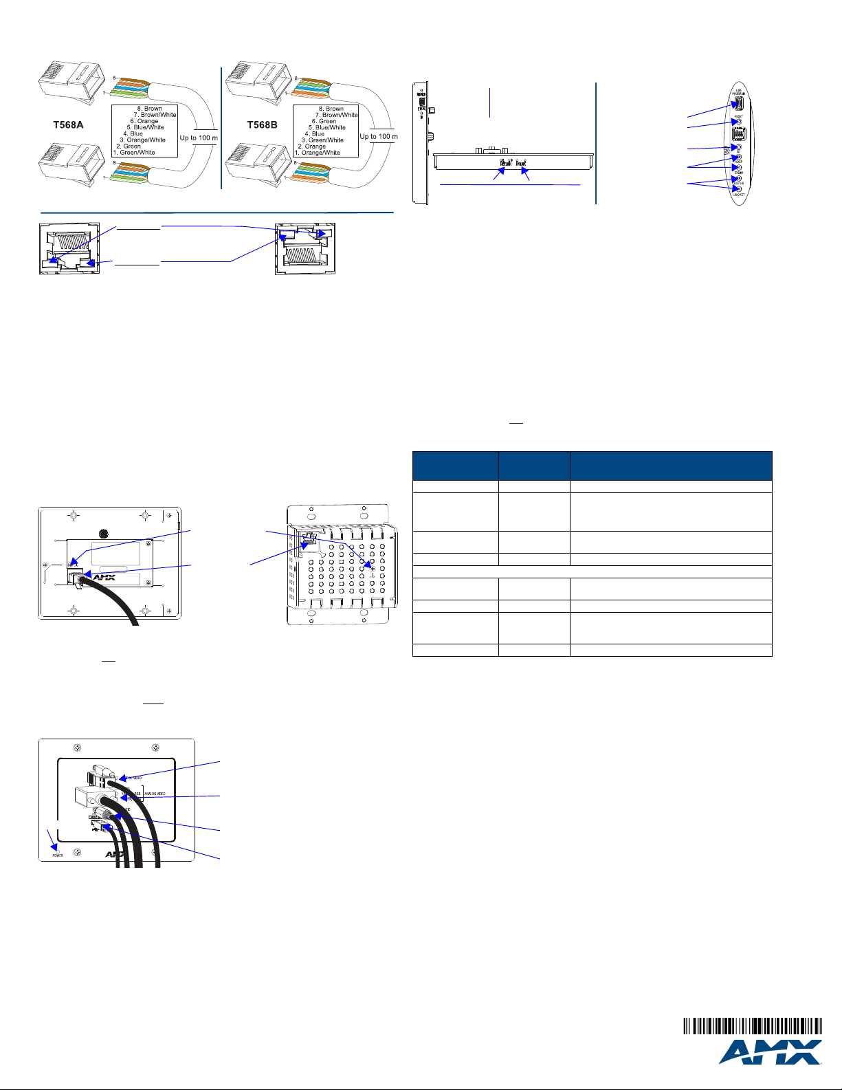
Twisted Pair Cable Pinouts and RJ-45 LEDs
Yellow LED
Green LED
On - Authenticated HDCP
Off - No Video
Blinking - Video active; no HDCP
On - Connection is active
Off - Connection is not active
Decor Wallplate TX
Wallplate TX
DXLink output
Wallplate TX
Ground screw (see
on previous page)
Decor Wallplate TX
connector
“Technical Ground”
USB Host
HDMI Input and
Stereo Audio Input
HD-15 Input and
Analog Video LEDs
and Audio LED
Digital Video LED
Power LED
Note: Connector
arrangement
differs between
the Wallplate TX
and Decor TX.
Wallplate TX - Bottom edge
NetLinx LEDs
DXLink LEDs
Program port
Reset button
ID button
Wallplate TX - Left edge
NetLinx LEDs
DXLink LEDs
Program port
Reset button
ID button
Decor Wallplate TX - Front
The DXLink port (RJ-45 connector) on the rear of the Transmitters uses twisted pair
cable. FIG. 5 shows two pinouts that can be used. FIG. 6 shows LEDs for the port.
FIG. 5
RJ-45 connector pinouts
FIG. 6 DXLink port LEDs
Before installing the Transmitter:
Wallplate TX – remove mounting bracket.
If a network connection is required, set #3 Toggle to ON.
If the gang box is not already installed, install it now (see previous page).
To install the Wallplate TX:
1. Attach the Wallplate TX mounting bracket to the gang box.
2. Attach a twisted pair cable from the DXLink Input Board on the switcher through
the mounting bracket to the DXLink connector on rear of Wallplate TX (FIG. 7).
3. Reattach the unit to the mounting bracket.
To install the Decor Wallplate TX:
1. Attach a twisted pair cable from the DXLink Input Board on the switcher to the
DXLink connector on the rear of the Decor Wallplate TX.
2. Attach unit to back box with four screws through the large screw holes.
3. Check LEDs for normal display (see table in right-hand column).
4. Attach customer provided decor style front cover plate to the unit.
FIG. 7 Connect twisted pair cable to DXLink connector on rear of TX (Wallplate TX shown)
Important: Do not
standard Ethernet Network. Use this connector for signal transport only.
use the RJ-45 connector on rear of the Transmitter to connect to a
Attaching Signal and Control Cables
Important: Transmitters must be securely mounted and connected to the switcher
before attaching the remaining cables.
To attach cables to the Transmitter:
USB Host Port Provides HID Support
The USB Host (mini-B) port on the front enables USB keyboard and mouse signals
from a DXLink RX to be sent to a connected PC.
Additional Buttons and Port
FIG. 9 Wallplate TX (left) and Decor Wallplate TX (right)
Reset Button
The Reset button resets the Transmitter’s CPU (see the Instruction Manual).
Program Port
This USB mini-B port supports DGX Configuration Software for programming a
custom EDID.
ID Button
The ID button can be used to toggle between static and DHCP IP addressing, assign
a device address, reset the factory defaults, and restore the factory firmware image
(see the Instruction Manual).
Powering the Wallplate TX and the Decor Wallplate TX
The switcher provides power for the TXs over twisted pair cable. Approved DXLink
power sourcing devices are listed in the Specifications table on the previous page.
Important: AMX does not
potentially damage the DXLink equipment.
support the use of any other PoE injectors as these may
This table shows LED states on initial power up. If not normal, check connections.
LED Power Up -
Indicates
Normal State
Digital Video* Green Configured to pass HDMI with embedded audio
Analog Video* One
Audio* Green Configured to pass analog audio (coupled with digital or
Power Green Power is applied
Wallplate TX LEDs (on bottom edge) and Decor Wallplate TX LEDs (front center)
NetLinx - L, Link/Act
NetLinx - S, Status Green Unit status
DXLink - Yellow, HDCP
DXLink - Green Green DXLink connection is established
* The LEDs for Digital Video, Analog Video, and Audio each indicate the configured state of
the connectors, not necessarily the presence of signals through the Transmitter.
** When an analog video signal is being received from the source device, only one of the
three analog video LEDs will be green at any time.
of the three LEDs
is Green**
Green Active LAN connection to an AMX Network
Yellow
Flashing
Off
Configured to pass analog video:
• C (composite) or Y/c (two component)
• Y/Pb/Pr or RGB (three component)
• RGBHV (five component) or RGBS (four component)
analog video path)
(Blinking = #3 Toggle OFF)
• Authenticated HDCP
• Video is active; no HDCP
•No Video
Tip: If the Wallplate TX’s location makes the bottom edge difficult to see, slide a white
piece of paper or a small mirror under the edge to view LED status.
Signal Precedence
With cables attached to each input on the Transmitters (see FIG. 8), the default
precedence for signal transmission is for HDMI with embedded digital audio. To
transmit either analog video or analog audio without detaching the HDMI connector,
the Transmitter’s precedence settings must be changed using SEND_COMMANDs.
For information, see the Instruction Manual.
FIG. 8 Attach signal and control cables (Wallplate TX shown)
1. HDMI input – Attach an HDMI cable from the source to HDMI In connector.
2. Analog video input – Attach HD-15 cable from source to analog video connector.
3. Stereo jack (optional) – Insert analog audio cable from source into Stereo jack.
4. USB Host (optional) – Attach USB cable from PC to USB (mini-B) port.
5. If necessary, set the video and audio formats using SEND_COMMANDs (see
the Instruction Manual).
6. Check LEDs for normal display (see table in right-hand column).
Note: Use DVI cable via an adapter (advanced HDMI audio support not available).
3000 RESEARCH DRIVE, RICHARDSON, TX 75082 • 800.222.0193 • fax 469.624.7153 • technical support 800.932.6993 • www.amx.com
©2013 AMX. All rights reserved. AMX and the AMX logo are registered trademarks of AMX.
For warranty information, see www.amx.com.
AMX reserves the right to alter specifications without notice at any time.
08/2013
Troubleshooting
Try the following and check the Instruction Manual before calling technical support.
Check all power connections in the system.
Check the RJ-45 (DXLink) cable connection between the Transmitter and
the switcher.
Check the source and destination devices to ensure that they function correctly.
Additional Information Covered in Instruction Manual
For information on the following, see the Instruction Manual – DXLink Twisted Pair
Transmitters/Receiver at www.amx.com:
• Pinouts for VGA, component, S-Video, and composite
• NetLinx control and programming commands, Telnet commands
• IR file transfers, upgrading firmware image, restoring factory default settings
 Loading...