

Page 1

1
Dual Stage Routing Systems
Technical Support
Dual Stage Routing Systems
Overview
A Dual Stage Routing (DSR) System is an Extended Routing System (ERS) with more inputs than
outputs, consisting of two or more distribution matrices that are linked and configured together.
DSR Systems are created for installations that require a large number of inputs and a considerably
smaller number of outputs. A DSR System has one or more (up to 16) pre-stage routers and one finalstage router. The number of inputs equals the total number of inputs used on all of the pre-stage routers,
plus any inputs on the final stage router that are not connected to the outputs from the pre-stage routers.
The number of outputs equals the number of outputs used on the final-stage router.
Additional input and output boards (besides the ones that are configured to route as the DSR System) can
be included on any of the routers in a DSR System; however, the additional boards on any individual
router must be configured on a separate virtual matrix and can only be used for routing inputs to outputs
on that router.
Technical Support
Important: The hardware and the distribution matrices used must
DSR System Setup – Example 1
The first DSR System setup example is for a 368x48 DSR System (see FIG. 1 on page 2) consisting of
the following three routers:
256x48 Epica-256 – used as the first pre-stage router
112x48 Epica-128 – used as the second pre-stage router
96x48 Epica-128 – used as the final-stage router
support dual stage routing.
Page 2
Technical Support
2
Dual Stage Routing Systems
LINK
STATUS
COMM
PORT 1
PORT 2
POWER
STATUS
110 - 220 V~ 50/60 Hz
300 W MAX EACH SUPPLY
450 W TOTAL FOR UNIT
5A 250V
70437
Conforms
UL Std. 1950
POWER
STATUS
110 - 220 V~ 50/60 Hz
300 W MAX EACH SUPPLY
450 W TOTAL FOR UNIT
5A 250V
70437
Conforms
UL Std. 1950
POWER
STATUS
110 - 220 V~ 50/60 Hz
300 W MAX EACH SUPPLY
450 W TOTAL FOR UNIT
5A 250V
70437
Conforms
UL Std. 1950
TO DISCONNECT POWER,
TURN OFF ALL POWER AND
UNPLUG ALL POWER CORDS.
POWER
STATUS
110 - 220 V~ 50/60 Hz
300 W MAX EACH SUPPLY
450 W TOTAL FOR UNIT
5A 250V
70437
Conforms
UL Std. 1950
POWER
STATUS
110 - 220 V~ 50/60 Hz
300 W MAX EACH SUPPLY
450 W TOTAL FOR UNIT
5A 250V
70437
Conforms
UL Std. 1950
POWER
STATUS
110 - 220 V~ 50/60 Hz
300 W MAX EACH SUPPLY
450 W TOTAL FOR UNIT
5A 250V
70437
Conforms
UL Std. 1950
TO DISCONNECT POWER,
TURN OFF ALL POWER AND
UNPLUG ALL POWER CORDS.
LINK
STATUS
COMM
PORT 1
PORT 2
POWER
STATUS
110 - 220 V~ 50/60 Hz
300 W MAX EACH SUPPLY
450 W TOTAL FOR UNIT
5A 250V
70437
Conforms
UL Std. 1950
POWER
STATUS
110 - 220 V~ 50/60 Hz
300 W MAX EACH SUPPLY
450 W TOTAL FOR UNIT
5A 250V
70437
Conforms
UL Std. 1950
POWER
STATUS
110 - 220 V~ 50/60 Hz
300 W MAX EACH SUPPLY
450 W TOTAL FOR UNIT
5A 250V
70437
Conforms
UL Std. 1950
TO DISCONNECT POWER,
TURN OFF ALL POWER AND
UNPLUG ALL POWER CORDS.
LINK
STATUS
COMM
PORT 1
PORT 2
Pre-Stage
Final-Stage
Termination
Termination
Ethernet
Control Link Cable
Control Link Cable
Pre-Stage
Router
Router
Router
Connector
Connector
x 48
x 48
48 DSR Outputs
48 User Outputs
1st 48 DSR Inputs
2nd 48 DSR Inputs
48 DSR Outputs
112 User Inputs
Routed as
Inputs 257 - 368
256 User Inputs
Routed as
Inputs 1 - 256
Connector
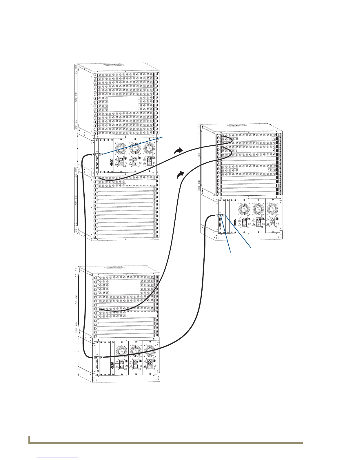
DSR Systems have one or more pre-stage routers and one final-stage router. FIG. 1 shows the outputs
from two pre-stage routers connected to the inputs on a final-stage router for a 368x48 DSR System.
FIG. 1 also shows the control link connections.
FIG. 1 Dual Stage Routing System – 368x48
Page 3

Technical Support
3
Dual Stage Routing Systems
LINK
STATUS
COMM
PORT 1
PORT 2
POWER
STATUS
110 - 220 V~ 50/60 Hz
300 W MAX EACH SUPPLY
450 W TOTAL FOR UNIT
5A 250V
70437
Conforms
UL Std. 1950
POWER
STATUS
110 - 220 V~ 50/60 Hz
300 W MAX EACH SUPPLY
450 W TOTAL FOR UNIT
5A 250V
70437
Conforms
UL Std. 1950
POWER
STATUS
110 - 220 V~ 50/60 Hz
300 W MAX EACH SUPPLY
450 W TOTAL FOR UNIT
5A 250V
70437
Conforms
UL Std. 1950
TO DISCONNECT POWER,
TURN OFF ALL POWER AND
UNPLUG ALL POWER CORDS.
Pre-Stage
256 User Inputs
Routed as
Inputs 1 - 256
64 DSR Outputs
Router
Final-Stage
Router
x 64
Termination
Connector
Control
Link Cable
Ethernet
Connector
Termination
Connector
192 User Inputs
Routed as
Inputs 257 - 448
64 User Outputs
64 DSR Inputs
DSR System Setup – Example 2
The second DSR system setup example is for a 448x64 DSR System (see FIG. 2), which only has one
pre-stage router. The outputs from the pre-stage router are connected to the inputs on the final-stage
router. FIG. 2 also shows the control link connections.
FIG. 2 Dual Stage Routing System – 448x64
Note: In FIG. 2, the 64 outputs on the pre-stage router are connected to the last 64 inputs on
the final-stage router. This allows the inputs on the pre-stage router to be configured and
routed as Inputs 1 through 256. The first 192 inputs on the final-stage router are then
configured and routed as Inputs 257 through 448.
Page 4

Technical Support
4
Dual Stage Routing Systems
Installation Procedure
Follow the instructions in the matrix switcher’s Instruction Manual to install the enclosures in racks.
Follow the guidelines below to link the enclosures for control (communication) and to attach the inputs
and outputs.
Linking Enclosures
All of the enclosures in a DSR System must be linked together for control. As long as all of their
communication ports are linked, the order they are linked is not important. For example, the pre-stage
routers can be linked from one to another, and then the last one can be linked to the final-stage router
(see FIG. 1). Or in the case of two pre-stage routers, they can both be linked to the final-stage router.
Important: When linking enclosures, be sure to attach 50 ohm termination connectors to the
open ends of all T-connectors.
Attaching Inputs & Outputs
The outputs on the pre-stage router(s) are connected to the inputs on the final-stage router. For
information on cabling specific types of connectors, see the router’s Installation Guide. When attaching
the input and output signal cables, refer to the sheet labeled “AutoPatch Connector Guide” shipped with
the product. The guide shows you where to attach each signal cable on the rear of each enclosure. (The
enclosure number is normally located on one of the expansion plates.) Follow the guide exactly; the
system was programmed at the factory to operate only as indicated on the “Connector Guide.”
System Control
Available Inputs & Outputs
The number of inputs and outputs available for switching depends on the configuration size of the DSR
System.
Inputs = Total number of inputs used on all pre-stage routers, plus any inputs on the final-stage
router that are not connected to the outputs from the pre-stage routers
Outputs = Number of outputs used on the final-stage router
For example (see FIG. 1), a DSR system consisting of a 256x48 pre-stage, a 112x48 pre-stage, and a
96x48 final-stage has the following available for switching:
Inputs = 368 (256 + 112)
Outputs = 48
The 48 outputs from each of the pre-stage routers are connected to the 96 inputs on the final-stage router.
Control
For control purposes, the numbering of the inputs starts on the first pre-stage router and continues on
each subsequent pre-stage router. Therefore, enclosures in a DSR System are controlled as if they were a
single router. For example, on the 368x48 DSR System in FIG. 1, the first pre-stage router switches
Inputs 1 though 256 and the second pre-stage router switches Inputs 257 though 368.
Remember, additional input or output boards (besides the ones being used for DSR System routing) can
be included in the system but must be switched on separate virtual matrices (VMs) that were created to
do so.
Page 5

Technical Support
5
Dual Stage Routing Systems
System Configuration
If the enclosures were ordered as a DSR System, the configuration file stored in the system is ready for
dual stage routing.
If you are creating a DSR System with existing equipment, the hardware must support dual stage routing
(to verify, contact technical support; see page 6) and the configuration file must be reconfigured and
loaded before the DSR System will work. If the configuration file needs to be reconfigured for DSR
System routing, we strongly recommend contacting technical support to request a modified file.
N
Caution: Use X
Connect only if you need to modify or customize your system’s configuration
from the original specifications. Be sure to make duplicate copies of the file before and after it is
modified and provide a copy of the modified file to technical support for future support.
A DSR System is created by combining each enclosure’s existing virtual matrices (VMs) in the
N
configuration (.xcl) file using X
Connect. The VMs that make up a DSR System are called constituent
VMs. The individual constituent VMs are not accessible for control purposes.
Tip: If you want to customize the channel names for a DSR System in the configuration file, do
so after the system has been created.
Creating a DSR Virtual Matrix
The simplest way to create a DSR System configuration is to use the Discover Hardware option in
N
Connect, create a constituent VM for each router, and then create the DSR VM using the constituent
X
VMs.
Tip: If additional VMs will be added to the system in the future, we suggest using relatively high
numbers (e.g., 30, 31, and 32) for the constituent VMs. This is because constituent VM
numbers are reserved (i.e., they cannot be reused for additional VMs within the system) and it
is usually easier to keep track of switching on lower numbered VMs.
To create the constituent VMs for DSR Systems:
1.
From the File menu, select Discover Hardware Only.
2. Create the final-stage VM using all of the inputs and outputs used in the final-stage router (see
“Creating a New Virtual Matrix” in the Help file).
3. Create a pre-stage VM using all of the pre-stage router’s inputs and a number of outputs that is
equal to the number of outputs used in the final-stage router.
4. Optional – Repeat Step 3 for each additional pre-stage VM.
Page 6

Technical Support
6
Dual Stage Routing Systems
To create a DSR VM:
From the Virtual Matrix menu, select Add DSR VM.
1.
The Configure a Dual Stage Routing System dialog box opens.
2. Under Available Virtual Matrices, select the VM for the final-stage router and click
Add Final-Stage VM.
3. Select a VM for one of the pre-stage routers and click Add Pre-Stage VM.
4. Repeat Step 3 for all remaining pre-stage VMs.
5. Check the DSR VM Dimensions at the bottom center of the dialog box to be sure that the
number of inputs and outputs are correct.
6. Click OK.
7. The DSR VM displays in the Virtual Matrix view (see the Note below).
8. Load the configuration to the system.
Note: From the Edit menu, under Advanced Parameters, select Nest Meta_VM Constituents
in Tree View to display all of the VMs in the DSR System. The default is “off” (do not display)
because the VMs that make up the DSR System are not accessible for control purposes.
Technical Support
Before contacting technical support with a question, please consult this supplement. If you still have
questions, contact your AMX representative or technical support. Have your serial numbers (normally
located on the rear of the enclosures) ready.
We recommend recording your serial numbers in an easily accessible location.
AMX Contact Information
3000 Research Drive, Richardson, TX 75082
800.222.0193
469.624.8000
Fax 469.624.7153
Technical Support 800.932.6993
www.amx.com
12/07 93-28-052 Rev: B
 Loading...