

AMX DGX800-ENC, DGX1600-ENC, DGX-I-HDMI, DGX-I-HDMI-4K, DGX-O-HDMI Hardware Reference Manual
...Page 1
HARDWARE REFERENCE MANUAL
ENOVA® DIGITAL MEDIA SWITCHERS
ENOVA DGX 100 SERIES ENCLOSURES
ENOVA DGX INPUT BOARDS
ENOVA DGX OUTPUT BOARDS
ENOVA DGX EXPANSION BOARDS
Page 2
IMPORTANT SAFETY INSTRUCTIONS
1. READ these instructions.
2. KEEP these instructions.
3. HEED all warnings.
4. FOLLOW all instructions.
5. DO NOT use this apparatus near water.
6. CLEAN ONLY with dry cloth.
7. DO NOT block any ventilation openings. Install in accordance with the manufacturer's instructions.
8. DO NOT install near any heat sources such as radiators, heat registers, stoves, or other apparatus (including amplifiers) that produce heat.
9. DO NOT defeat the safety purpose of the polarized or grounding type plug. A polarized plug has two blades with one wider than the other. A
grounding type plug has two blades and a third grounding prong. The wider blade or the third prong are provided for your safety. If the provided plug
does not fit into your outlet, consult an electrician for replacement of the obsolete outlet.
10. PROTECT the power cord from being walked on or pinched, particularly at plugs, convenience receptacles, and the point where they exit from the
apparatus.
11. ONLY USE attachments/accessories specified by the manufacturer.
12. USE ONLY with a cart, stand, tripod, bracket, or table specified by the manufacturer, or sold with the apparatus. When a cart is used, use caution
when moving the cart/apparatus combination to avoid injury from tip-over.
13. UNPLUG this apparatus during lightning storms or when unused for long periods of time.
14. REFER all servicing to qualified service personnel. Ser vicing is required when the apparatus has been damaged in any way, such as power-supply cord
or plug is damaged, liquid has been spilled or objects have fallen into the apparatus, the apparatus has been exposed to rain or moisture, does not
operate normally, or has been dropped.
15. DO NOT expose this apparatus to dripping or splashing and ensure that no objects filled with liquids, such as vases, are placed on the apparatus.
16. To completely disconnect this apparatus from the AC Mains, disconnect the power supply cord plug from the AC receptacle.
17. Where the mains plug or an appliance coupler is used as the disconnect device, the disconnect device shall remain readily operable.
18. DO NOT overload wall outlets or extension cords beyond their rated capacity as this can cause electric shock or fire.
The exclamation point, within an equilateral triangle, is intended to aler t the user to the presence of important operating and maintenance (ser vicing) instructions in
the literature accompanying the product.
The lightning flash with arrowhead symbol within an equilateral triangle is intended to alert the user to the presence of uninsulated "dangerous voltage" within the
product's enclosure that may be of sufficient magnitude to constitute a risk of electrical shock to persons.
ESD Warning: The icon to the left indicates text regarding potential danger associated with the discharge of static electricity from an outside source (such as human
hands) into an integrated circuit, often resulting in damage to the circuit.
WARNING: To reduce the risk of fire or electrical shock, do not expose this apparatus to rain or moisture.
WARNING: No naked flame sources - such as lighted candles - should be placed on the product.
WARNING: Equipment shall be connected to a MAINS socket outlet with a protective earthing connection.
WARNING: To reduce the risk of electric shock, grounding of the center pin of this plug must be maintained.
COPYRIGHT NOTICE
AMX© 2018, all rights reserved. No part of this publication may be reproduced, stored in a retrieval system, or transmitted, in any form or by any means, electronic,
mechanical, photocopying, recording, or otherwise, without the prior written permission of AMX. Copyright protection claimed extends to AMX hardware and software and
includes all forms and matters copyrightable material and information now allowed by statutory or judicial law or herein after granted, including without limitation, material
generated from the software programs which are displayed on the screen such as icons, screen display looks, etc. Reproduction or disassembly of embodied computer
programs or algorithms is expressly prohibited.
LIABILITY NOTICE
No patent liability is assumed with respect to the use of information contained herein. While ever y precaution has been taken in the preparation of this publication, AMX
assumes no responsibility for error or omissions. No liability is assumed for damages resulting from the use of the information contained herein. Further, this publication and
features described herein are subject to change without notice.
AMX WARRANTY AND RETURN POLICY
The AMX Warranty and Return Policy and related documents can be viewed/downloaded at www.amx.com.
Page 3
3
Enova Digital Media Switchers - Hardware Reference Manual
WARNING: This product is intended to be operated ONLY from the voltages listed on the back panel or the recommended, or
included, power supply of the product. Operation from other voltages other than those indicated may cause irreversible damage to
the product and void the products warranty. The use of AC Plug Adapters is cautioned because it can allow the product to be
plugged into voltages in which the product was not designed to operate. If the product is equipped with a detachable power cord,
use only the type provided with your product or by your local distributor and/or retailer. If you are unsure of the correct operational
voltage, please contact your local distributor and/or retailer.
BATTERY INSTRUCTIONS
THIS PRODUCT CONTAINS A LITHIUM PACK OR COIN/BUTTON CELL BATTERY. IF MISUSED OR ABUSED THIS CAN RESULT IN:
•Smoke or gas hazard
• Heat hazard
•Fire hazard
•Explosion hazard
WARNING: Do not place batteries in mouth or ingest. Chemical burn hazard. Keep new and used batteries out of reach of children and
pets. If swallowed, it can cause severe internal burns in just 2 hours and can lead to death.
If you think batteries might have been swallowed or placed inside any part of the body, seek immediate medical attention.
WARNING: If battery compartment does not close securely, stop using the product and keep it away from children and pets.
WARNING: Do not handle leaking or damaged Lithium batteries.
WARNING: Risk of leakage. Only use the specified type of batteries. Never mix new and used batteries.
Observe correct polarity. Remove batteries from products that are not in use for extended periods of time. Store batteries in a dry place.
WARNING: Batteries (battery pack or batteries installed) shall not be exposed to excessive heat such as sunshine, fire or the like.
WARNING: Danger of explosion if battery is incorrectly replaced. Replace only with the same or equivalent type.
Dispose of used batteries according to the instructions.
WARNING: Do not recharge non-rechargeable batteries.
WARNING: Avoid exposure to extreme heat or cold.
Please dispose of any used batteries properly, following any local regulations. Do no t incinerate.
EU COMPLIANCE INFORMATION
Eligible to bear the CE mark; Conforms to European Union Low Voltage Directive 2014/35/EU; European Union EMC Directive
2014/30/EU; European Union Restriction of Hazardous Substances Recast (RoHS2) Directive 2011/65/EU; European Union WEEE
(recast) Directive 2012/19/EU; European Union Eco-Design Directive 2009/125/EC; European Union Registration, Evaluation,
Authorization and Restriction of Chemicals (REACH) Regulation (EC) 1907/2006.
You may obtain a free copy of the Declaration of Conformity by visiting http://www.amx.com/techcenter/certifications.asp.
WEEE NOTICE
This appliance is labeled in accordance with European Directive 2012/19/EU concerning waste of electrical and electronic equipment
(WEEE). This label indicates that this product should not be disposed of with household waste. It should be deposited at an appropriate
facility to enable recovery and recycling.
US FCC COMPLIANCE NOTICE - CLASS A
NOTE: This equipment has been tested and found to comply with the limits for a Class A digital device, pursuant to part 15 of the FCC
Rules. These limits are designed to provide reasonable protection against harmful interference when the equipment is
operated in a commercial environment. This equipment generates, uses, and can radiate radio frequency energy, and if it is
not installed and used in accordance with the instruction manual, it may cause harmful interference to radio communications.
Operation of this equipment in a residential area is likely to cause harmful interference, in which case the user will be required
to correct the interference at his own expense.
US FCC AND CANADA EMC COMPLIANCE INFORMATION:
This device complies with part 15 of the FCC Rules. Operation is subject to the following two conditions:
(1) This device may not cause harmful interference, and (2) this device must accept any interference received, including
interference that may cause undesired operation.
CANADA ICES INFORMATION
ICES (Interference-Causing Equipment Standard): CAN ICES-3 (A)/NMB-3(A)
Page 4

4
Enova Digital Media Switchers - Hardware Reference Manual
ESD WARNING
To avoid ESD (Electrostatic Discharge) damage to sensitive components, make sure you are properly grounded before touching any
internal materials.
When working with any equipment manufactured with electronic devices, proper ESD grounding procedures must be followed to make sure
people, products, and tools are as free of static charges as possible. Grounding straps, conductive smocks, and conductive work mats are
specifically designed for this purpose.
Anyone performing field maintenance on AMX equipment should use an appropriate ESD field service kit complete with at least a
dissipative work mat with a ground cord and a UL listed adjustable wrist strap with another ground cord.
These items should not be manufactured locally, since they are generally composed of highly resistive conductive materials to safely d rain
static charges, without increasing an electrocution risk in the event of an accident.
LICENSE NOTICES AND TRADEMARK ACKNOWLEDGMENTS
Java® is a registered trademark of Oracle and/or its affiliates.
Manufactured under license from Dolby Laboratories. Dolby
Laboratories.
®
DTS
, the Symbol, DTS-HD®, and DTS® or DTS-HD® and the Symbol together are registered trademarks of DTS, Inc., and all other
®
DTS
logos are trademarks of DTS, Inc.
®
Windows
Google Chrome
Firefox
Safari
Opera
UL
3M
Ethernet
ENERGY STAR
and Internet Explorer® are registered trademarks of Microsoft Corporation in the United States and other countries.
®
®
is a registered trademark of the Mozilla Foundation.
®
is a registered trademark of Apple Inc.
®
is a registered trademark of Opera Software ASA.
®
and the UL logo are trademarks of UL LLC.
®
, Desco®, Richmond Technology®, and Plastic Systems® are registered trademarks.
®
is a registered trademark of Google Inc.
is a registered trademark of the Xerox Corporation.
®
is a registered trademark of the U.S. Department of Energy and the U.S. Environmental Protection Agency.
Other products mentioned herein may be the trademarks of their respective owners.
®
and the double-D symbol are registered trademarks of Dolby
TRADEM A RK L O GO S
Page 5

5
Enova Digital Media Switchers - Hardware Reference Manual
CHINA MARKINGS (ONLY FOR INSTALLATIONS LOCATED IN CHINA)
该设备的设计和测试是在海拔 2000 米高度以下进行的 , 它只适用在海拔 2000 米以下的地区 .在海拔 2000 米以上使用可能会导致潜
在的安全隐患 .
This symbol denotes that the device is not to be used at altitudes exceeding 2000 meters.
该设备的设计和测试是在非热带气候条件进行的 , 它只适用在非热带气候的地区 . 在热带气候地区使用可能会导致潜在的安全隐患 .
This symbol denotes that the device is only to be used in climate regions that are not-tropical.
Page 6

6
Enova Digital Media Switchers - Hardware Reference Manual
Table of Contents
Enova DGX 100 Series - Overview ..........................................................................................25
Applicability Notice....................................................................................................................... 25
DGX Digital Media Switchers & Standard Video Input and Output Boards..................................... 25
Enova DGX HDMI 4K60 Boards............................................................................................................... 25
Enova DGX HDMI Boards ....................................................................................................................... 25
Enova DGX DVI Boards........................................................................................................................... 25
Enova DGX DXLink Twisted Pair Boards ................................................................................................ 25
Enova DGX DXLink Twisted Pair 4K Boards........................................................................................... 26
Enova DGX DXLink Fiber Boards ........................................................................................................... 26
Input and Output Boards and Signal Types ............................................................................................ 26
Input and Output Board Connectors ...................................................................................................... 26
Connectors and Signal Types ................................................................................................................ 27
Enova DGX Expansion Boards....................................................................................................... 27
Audio Switching Board (ASB-DAN and ASB) Sets (page 164)................................................................. 27
Enova DGX Audio Insert/Extract Board (page 175) ................................................................................ 27
Important Notes on Using Expansion Boards..................................................................................................... 28
Integrated NetLinx NX Master Functionality ................................................................................ 28
Network Connection .............................................................................................................................. 28
DHCP Server ......................................................................................................................................... 28
Opening Public LAN and ICS LAN Sockets from Code............................................................................ 28
Integrated NetLinx NX Master Features ............................................................................................... 28
The integrated NetLinx NX Master supports the following features:................................................................ 28
Automatic Configuration of AMX Devices via ICS LAN ........................................................................... 28
Link-local Fallback in DHCP Mode (IPv4 Only) ...................................................................................... 29
Wired 802.1x Support............................................................................................................................ 29
Support for IPv6 Network Addressing................................................................................................... 29
ID Pushbutton........................................................................................................................................ 29
Case Sensitive File System.................................................................................................................... 29
USB Program Port Driver...................................................................................................................... 29
Differences in DEFINE_PROGRAM Execution........................................................................................ 29
Enova DGX NetLinx and Control Specifications ............................................................................ 30
Configuration Information and Control Options............................................................................ 30
Switching Configuration Information .................................................................................................... 30
Embedded Audio Signals ....................................................................................................................... 30
Available Levels (Virtual Matrices) ....................................................................................................... 31
Audio Switching Boards......................................................................................................................... 31
Board Configuration Information .......................................................................................................... 31
Control Options ..................................................................................................................................... 31
Integrated NetLinx NX Central Control Processor.............................................................................................. 31
Control Panel.......................................................................................................................................................... 31
AMX Control Devices............................................................................................................................................. 31
BCS (Basic Control Structure) Protocol .............................................................................................................. 31
Third-Party Controllers.......................................................................................................................................... 31
Enova DGX 100 Series and Enova DGX 8/16/32/64: Differences ................................................... 32
System Diagnostic Options ........................................................................................................... 33
System Configuration Interface - Status Page ...................................................................................... 33
DGX_SHELL Commands ........................................................................................................................ 33
InstaGate Pro Technology............................................................................................................. 34
Page 7

7
Enova Digital Media Switchers - Hardware Reference Manual
DGX 800 .................................................................................................................................35
Front Panel................................................................................................................................... 35
Power Indicator LED Behavior .............................................................................................................. 35
Rear Panel.................................................................................................................................... 35
Power Supplies (x2) .............................................................................................................................. 35
Specifications ............................................................................................................................... 36
DGX 1600 ...............................................................................................................................37
Front Panel................................................................................................................................... 37
Power Indicator LED Behavior .............................................................................................................. 37
Rear Panel.................................................................................................................................... 37
Power Supplies (x2) .............................................................................................................................. 37
Specifications ............................................................................................................................... 38
DGX 3200 ...............................................................................................................................39
Front Panel................................................................................................................................... 39
Power Indicator LED Behavior .............................................................................................................. 39
Rear Panel.................................................................................................................................... 39
Power Supplies (x2) .............................................................................................................................. 39
Specifications ............................................................................................................................... 40
DGX 6400 ...............................................................................................................................41
Front Panel................................................................................................................................... 41
Power Indicator LED Behavior .............................................................................................................. 41
Rear Panel.................................................................................................................................... 42
Power Supplies (x4) .............................................................................................................................. 42
Specifications ............................................................................................................................... 43
Installation and Setup ...........................................................................................................44
DGX Enclosure MAC Address / Serial Number ............................................................................ 44
DXLink Fiber Boards..................................................................................................................... 44
Safety Recommendations for Laser Products .............................................................................. 44
General Hazard Precautions......................................................................................................... 44
Elevated Operating Temperature .......................................................................................................... 44
Airflow Restriction ................................................................................................................................ 44
Mechanical (Rack) Loading.................................................................................................................... 45
Circuit Overloading ............................................................................................................................... 45
Reliable Earthing (Grounding)............................................................................................................... 45
Site Recommendations................................................................................................................. 45
Environment.......................................................................................................................................... 45
Chassis Accessibility ............................................................................................................................. 45
Power .................................................................................................................................................... 45
System Setup with Transmitters and Receivers ........................................................................... 45
Options for System Setup with DXLink Twisted Pair ............................................................................. 45
Options for System Setup with DXLink Twisted Pair 4K ........................................................................ 46
Options for System Setup with DXLink Fiber......................................................................................... 46
Unpacking..................................................................................................................................... 46
Unpacking Tips ...................................................................................................................................... 46
Rack Installation and System Setup ............................................................................................. 47
Required Items ....................................................................................................................................................... 47
Optional Items ........................................................................................................................................................ 47
Recommendations ................................................................................................................................................. 47
Installation Procedure .......................................................................................................................... 47
Page 8

8
Enova Digital Media Switchers - Hardware Reference Manual
Rack-Mounting Enova DGX 100 Series Enclosures ....................................................................... 48
Rack-Mounting DGX 6400 Enclosures ................................................................................................... 48
Rack-Mounting DGX 800/1600/3200 Enclosures ................................................................................... 49
Installing Boards, Connecting Devices and Powering up the DGX Enclosure ........................................ 49
Special Information for Audio Expansion Boards .................................................................................. 49
Installation Options................................................................................................................................................ 50
Attaching Cable Management Bars ....................................................................................................... 50
Attaching Video Input and Output Cables...................................................................................... 51
Enova DGX 800....................................................................................................................................... 51
Enova DGX 1600..................................................................................................................................... 51
Enova DGX 3200..................................................................................................................................... 51
Enova DGX 6400..................................................................................................................................... 51
Cabling Specific Connector Types ......................................................................................................... 51
Input and Output Signal Cables ............................................................................................................. 51
Wiring Audio Inputs and Outputs .................................................................................................. 52
System Setup for Using the Integrated NetLinx NX Master .......................................................... 52
System Setup Overview ......................................................................................................................... 52
RJ-45 Ports ........................................................................................................................................... 53
RJ-45 Port LEDs ..................................................................................................................................................... 53
ICS LAN 10/100 and LAN 100/1000 Indicator LEDs .......................................................................................... 53
Cable Requirements and Pinouts......................................................................................................................... 53
T568A....................................................................................................................................................................... 53
T568B....................................................................................................................................................................... 54
ICS LAN 10/100 Port............................................................................................................................................... 54
LAN 100/1000 Port.................................................................................................................................................. 54
IP Protocols Used by the Enova DGX Integrated Controller................................................................... 54
Avoiding Network (Ethernet) Loops.............................................................................................. 55
Connecting an Enova DGX to a Public LAN via the LAN 100/1000 Port .................................................. 56
Confirming Board Versions .......................................................................................................... 56
System Configuration Interface Setup.......................................................................................... 57
System Requirements............................................................................................................................................ 57
Logging On To the System Configuration Interface and Executing a Test Switch .................................. 57
Additional Setup Options ...................................................................................................................................... 57
Audio Control and Signal Processing Options............................................................................... 58
Audio Switching Boards (ASB)............................................................................................................... 58
System Configuration Interface............................................................................................................................ 58
ICSP Commands .................................................................................................................................................... 58
Control Panel.......................................................................................................................................................... 58
BCS Commands ..................................................................................................................................................... 58
Establishing Serial Communication with a PC via the Program Port ............................................ 58
Program Port ........................................................................................................................................ 58
Cable Requirements............................................................................................................................................... 58
Program Port LEDs – Modes and LED Blink Patterns ..................................................................................... 58
Attaching an AxLink Device .......................................................................................................... 59
AxLink LED ............................................................................................................................................ 59
Using the AxLink Connector for Data and Power................................................................................... 59
AxLink Device Numbering ..................................................................................................................... 59
Setting an AxLink Device Address......................................................................................................... 60
AxLink Power Measurement and Control.............................................................................................. 60
AxLink Port Diagnostics ........................................................................................................................ 60
Using the ID Pushbutton ............................................................................................................... 60
Toggling Between DHCP and Static IP Addressing ................................................................................ 60
Page 9

9
Enova Digital Media Switchers - Hardware Reference Manual
Resetting the Factory Default Settings: ................................................................................................ 60
Restoring the Factory Firmware Image and Factory Default Settings .................................................. 61
Program Run Disable (PRD) Mode ................................................................................................ 61
Setting the Config DIP Switch To Place the Integrated Master in PRD Mode ......................................... 61
Troubleshooting and Technical Support....................................................................................... 61
Troubleshooting .................................................................................................................................... 61
Enova DGX Switcher Hardware Troubleshooting............................................................................................... 61
Video and Audio Troubleshooting........................................................................................................................ 62
AMX Software Troubleshooting............................................................................................................................ 62
Contacting Technical Support................................................................................................................ 62
AMX Contact Information ...................................................................................................................................... 62
Applying Power and Startup ..................................................................................................63
Overview....................................................................................................................................... 63
Power Budget Planning for Systems with DXLink Twisted Pair Boards ....................................... 63
Complete Power Redundancy Setup............................................................................................. 63
Power-Up Sequence .............................................................................................................................. 63
Applying Power ............................................................................................................................ 64
Indicator Lights at Startup .................................................................................................................... 64
Redundant Power Supply (RPS).................................................................................................... 65
Power Supply Troubleshooting ............................................................................................................................ 65
CPU/Control Board (all DGX 100 Series Enclosures) ............................................................66
Overview....................................................................................................................................... 66
Control Panel ........................................................................................................................67
Overview....................................................................................................................................... 67
Control Keys and Dial ............................................................................................................... 67
Input and Output Keys .................................................................................................................. 68
Function Menus and Modes ................................................................................................................... 68
Enova DGX Control Panel - Basic Tasks ............................................................................................................. 69
Labeling Input and Output Keys............................................................................................................. 69
Creating and Installing Custom Labels for Input and Output Keys ........................................................ 69
Executing Switches....................................................................................................................... 70
Executing a Test Switch......................................................................................................................... 70
Controlling Switches on Systems with Audio Switching Boards............................................................ 70
Changing the Virtual Matrix.......................................................................................................... 71
Changing the Virtual Matrix .................................................................................................................. 71
Disconnecting Switches ................................................................................................................ 71
Disconnecting Inputs and Outputs ......................................................................................................... 71
Verifying Signal Status ................................................................................................................. 72
Defining and Executing Global Presets......................................................................................... 72
Systems without Audio Switching Boards (ASB or ASB-DAN) ............................................................... 73
Systems with Audio Switching Boards (ASB or ASB-DAN) .................................................................... 73
Defining a Global Preset........................................................................................................................ 73
Executing a Global Preset ..................................................................................................................... 73
Locking and Unlocking.................................................................................................................. 74
Locking the Control Panel ..................................................................................................................... 74
Unlocking the Control Panel.................................................................................................................. 74
Adjusting Audio (Systems with Audio Switching Boards Only)...................................................... 74
Audio Adjustments on the Control Panel ............................................................................................................ 75
Adjusting Volume .................................................................................................................................. 75
Page 10

10
Enova Digital Media Switchers - Hardware Reference Manual
Muting and Unmuting Outputs ............................................................................................................... 75
Unmuting an Output While In Mute Mode .............................................................................................. 76
Adjusting Input Gain .............................................................................................................................. 76
Setup Options ............................................................................................................................... 76
Software Version................................................................................................................................... 77
Checking Software Version Information................................................................................................ 77
Master Info ............................................................................................................................................ 77
Checking Integrated Master Info ........................................................................................................... 77
Default Virtual Matrix............................................................................................................................ 78
Reload Config ........................................................................................................................................ 78
Setting the Password ............................................................................................................................ 79
System Error Codes and Troubleshooting.................................................................................... 79
Enabling Error Code Reporting ............................................................................................................. 80
Turning Error Code Reporting Off ......................................................................................................... 80
Error Code Troubleshooting ................................................................................................................. 80
4K60 HDMI Input & Output Boards ........................................................................................81
Overview....................................................................................................................................... 81
Signal Routing .............................................................................................................................. 81
DGX Board Compatibility ....................................................................................................................... 81
4K60 Signal Routing .............................................................................................................................. 82
Video Signal Tiers Support .................................................................................................................... 82
3rd Party Equipment Requirements for DGX 4K60 HDMI Boards .......................................................... 82
Enova DGX 4K60 4:4:4 HDMI Input Board - Specifications ............................................................ 83
Enova DGX 4K60 4:4:4 HDMI Output Board - Specifications ......................................................... 84
4K60 HDMI Board Default EDID Resolutions Supported through Local DDC................................. 85
4K HDMI DTD (Detailed Timing Descriptor) ...................................................................................... 85
4K HDMI CTA Video Information Code (VIC) Formats ............................................................................ 85
Audio Data Block.................................................................................................................................................... 86
4K60 HDMI Board EDID Resolutions - 50 Hz and 60 Hz Modes ...................................................... 86
Detailed Timings ................................................................................................................................ 86
HDMI VICs ............................................................................................................................................. 86
Short Video Descriptors ....................................................................................................................... 86
4K HDMI Standard Timings ................................................................................................................... 87
4K HDMI Established Timings ............................................................................................................... 87
Standard Timings ................................................................................................................................. 87
Established Timings ............................................................................................................................. 87
Audio Data Block.................................................................................................................................................... 87
Attaching HDMI Connectors.......................................................................................................... 88
Executing a Test Switch for an HDMI Board.................................................................................. 88
HDCP Support on Enova DGX 4K60 Switchers............................................................................... 88
Video Troubleshooting.................................................................................................................. 89
Audio Troubleshooting ................................................................................................................. 91
Determining the DxLink Transmitter Source Audio Port ................................................................................... 94
Audio Format Support on Enova DGX Boards ........................................................................................ 94
HDMI Input & Output Boards .................................................................................................95
Overview....................................................................................................................................... 95
Signal Routing .............................................................................................................................. 95
4K Signal Routing .................................................................................................................................. 95
InstaGate Pro and SmartScale .............................................................................................................. 96
Page 11

11
Enova Digital Media Switchers - Hardware Reference Manual
Enova DGX HDMI Input Board - Specifications ............................................................................. 96
Enova DGX HDMI Output Board - Specifications ........................................................................... 99
HDMI Board EDID Resolutions Supported via Local DDC ............................................................ 100
Standard Timings (Default Shipping EDID)........................................................................................... 100
Established Timings ............................................................................................................................. 100
HDMI CTA Video Information Code (VIC) Formats................................................................................. 101
Audio Data Block .................................................................................................................................. 101
4K HDMI Board EDID Resolutions Supported through Local DDC ............................................... 101
4K HDMI DTD (Detailed Timing Descriptor ........................................................................................... 101
4K HDMI Standard Timings................................................................................................................... 102
4K HDMI Established Timings .............................................................................................................. 102
4K HDMI CTA Video Information Code (VIC) Formats ........................................................................... 102
Audio Data Block .................................................................................................................................. 102
Attaching HDMI Connectors........................................................................................................ 103
Executing a Test Switch for an HDMI Board................................................................................ 103
HDCP Support on Enova DGX Switchers ..................................................................................... 103
HDMI System Conditions ...................................................................................................................... 103
Steps in the Content Protection Process .............................................................................................. 103
Supported Number of Sinks ................................................................................................................. 104
HDCP Source Device ........................................................................................................................................... 104
Enova DGX Switcher............................................................................................................................................ 104
Unsuccessful Transmission in System ................................................................................................. 104
Video Troubleshooting................................................................................................................ 104
Audio Troubleshooting ............................................................................................................... 105
Audio Format Support on Enova DGX Boards ....................................................................................... 105
DVI Input & Output Boards ...................................................................................................106
Overview..................................................................................................................................... 106
Signal Routing ............................................................................................................................ 106
InstaGate Pro and SmartScale ............................................................................................................. 106
Audio Support on DVI Boards ............................................................................................................... 107
Enova DGX DVI Boards - Specifications....................................................................................... 107
EDID Resolutions Supported through Local DDC ........................................................................ 108
Standard Timings (Default shipping EDID) ........................................................................................... 108
Established Timings ............................................................................................................................. 108
CTA Video Information Code (VIC) Formats .......................................................................................... 109
Audio Data Block .................................................................................................................................. 109
Connecting DVI Inputs and Outputs............................................................................................. 109
DVI Pinout................................................................................................................................... 110
Troubleshooting Video................................................................................................................ 110
Troubleshooting Audio ............................................................................................................... 111
Audio Format Support on Enova DGX Boards ....................................................................................... 111
DXLink Twisted Pair Input and Output Boards .................................................................... 112
Overview..................................................................................................................................... 112
Signal Routing ............................................................................................................................ 112
HDCP Compliance................................................................................................................................. 112
InstaGate Pro Technology .................................................................................................................... 113
DXLink - Twisted Pair Boards Specifications.............................................................................. 113
Compatible AMX DXLink - Twisted Pair Transmitters and Receiver .................................................... 113
Page 12

12
Enova Digital Media Switchers - Hardware Reference Manual
Compatible AMX Solecis Digital Switchers (1 Output per Switcher)..................................................... 113
EDID Resolutions Supported through Local DDC ........................................................................ 114
Standard Timings (Default Shipping EDID)........................................................................................... 114
Established Timings ............................................................................................................................. 115
CTA Video Information Code (VIC) Formats .......................................................................................... 115
Audio Data Block.................................................................................................................................................. 115
System Setup with DXLink Transmitters and Receivers............................................................. 116
Options for DXLink System Setup ......................................................................................................... 116
DXLink Transmitter/Receiver Grounding ............................................................................................. 116
Example of Typical Setup with DXLink Transmitter and Receiver........................................................ 116
Functions of DXLink Transmitters and Receivers ................................................................................ 117
Important Power Considerations for Enova DGX 3200 Endpoint Systems ............................................ 118
Power Budget Planning for Enova DGX 3200 with DXLink Boards .............................................. 118
Power Budget Calculation .................................................................................................................... 118
Foregoing Power Supply Redundancy.................................................................................................. 118
In the Event of a Power Supply Failure................................................................................................. 118
Connecting Switching Systems with DXLink Connectors...................................................................... 119
Avoiding Network (Ethernet) Loops ..................................................................................................... 119
Important Twisted Pair Cabling Requirements and Recommendations ............................................... 119
Twisted Pair Cable Pinouts .................................................................................................................. 119
Connecting Sources and Destinations to DXLink Inputs and Outputs via TX/RX ................................... 119
DXLink Connector LEDs........................................................................................................................ 120
Configuring DXLink Endpoints for Communication with a Master .............................................. 120
Best Practices for Configuration .......................................................................................................... 120
DIP Switch Toggles............................................................................................................................... 120
Auto-setup.................................................................................................................................. 121
Need to Know for Auto-setup ............................................................................................................... 121
Disabling Auto-setup Mode .................................................................................................................. 121
Enabling Auto-setup Mode ................................................................................................................... 121
Enable Auto-setup Mode via DGX_SHELL Commands.................................................................................... 121
Telnet Access to Endpoints in Auto-setup Mode................................................................................... 121
Telnet Access to DXLink Endpoints ...................................................................................................... 122
Serial Data Transfer and IR Flow Control................................................................................... 122
DXLink Twisted Pair / DXLink Twisted Pair 4K Compatibility ..................................................... 122
Troubleshooting Audio ............................................................................................................... 122
DXLink Twisted Pair 4K Input and Output Boards ...............................................................123
Overview..................................................................................................................................... 123
Signal Routing ............................................................................................................................ 123
HDCP Compliance................................................................................................................................. 124
InstaGate Pro Technology .................................................................................................................... 124
DXLink Twisted Pair 4K Boards Specifications ........................................................................... 124
Compatible AMX DXLink- Twisted Pair 4K Transmitters and Receivers: ............................................. 124
Compatible AMX Solecis 4K Digital Switchers (1 Output per Switcher):............................................... 124
EDID Resolutions Supported through Local DDC ........................................................................ 125
DTD (Detailed Timing Descriptor)......................................................................................................... 125
Standard Timings ................................................................................................................................. 126
Established Timings ............................................................................................................................ 126
CTA Video Information Code (VIC) Formats .......................................................................................... 126
Audio Data Block .................................................................................................................................. 127
System Setup with DXLink Twisted Pair 4K Transmitters and Receivers................................... 127
Page 13

13
Enova Digital Media Switchers - Hardware Reference Manual
Options for DXLink System Setup ......................................................................................................... 127
Example of Typical Setup with DXLink Twisted Pair 4K Transmitter and Receiver.............................. 127
Functions of DXLink Transmitters and Receivers ................................................................................ 128
Important Power Considerations for Enova DGX 3200 Endpoint Systems ............................................ 128
Power Budget Planning for Enova DGX 3200 with DXLink Boards .............................................. 129
Power Budget Calculation .................................................................................................................... 129
Foregoing Power Supply Redundancy.................................................................................................. 129
In the Event of a Power Supply Failure................................................................................................. 129
Connecting Switching Systems with DXLink Connectors...................................................................... 129
Avoiding Network (Ethernet) Loops ..................................................................................................... 130
Important DXLink Twisted Pair 4K Cabling Requirements and Recommendations.............................. 130
Twisted Pair Cable Pinouts .................................................................................................................. 130
Connecting Sources and Destinations to DXLink Inputs and Outputs via TX/RX ................................... 130
DXLink Connector LEDs........................................................................................................................ 131
Configuring DXLink Endpoints for Communication with a Master .............................................. 131
Best Practices for Configuration .......................................................................................................... 131
DIP Switch Toggles............................................................................................................................... 131
Auto-setup.................................................................................................................................. 132
Need to Know for Auto-setup ............................................................................................................... 132
Disabling Auto-setup Mode .................................................................................................................. 132
Enabling Auto-setup Mode ................................................................................................................... 132
Telnet Access to Endpoints in Auto-setup Mode................................................................................... 132
Telnet Access to DXLink Twisted Pair 4K Receivers............................................................................. 132
DXLink Twisted Pair / DXLink Twisted Pair 4K Compatibility ..................................................... 133
Troubleshooting ................................................................................................................................... 133
DXLink Fiber Input & Output Boards ...................................................................................134
Overview..................................................................................................................................... 134
DXLink Fiber Boards, Duplex ............................................................................................................... 134
DXLink Fiber Boards, Simplex.............................................................................................................. 134
Warning: Optical Fiber Products ................................................................................................ 135
OSHA Directive ..................................................................................................................................... 135
Signal Routing ............................................................................................................................ 135
HDCP Compliance................................................................................................................................. 135
InstaGate Pro Technology .................................................................................................................... 135
DXLink Fiber Hardware Compatibility ........................................................................................ 135
Compatible DXLink Fiber Transmitters and Receivers ........................................................................ 135
DXLink Fiber Directional Modes ................................................................................................. 136
Bidirectional Mode ............................................................................................................................... 136
Unidirectional Mode ............................................................................................................................. 136
Data Link-lost Mode ............................................................................................................................. 136
Enova DGX DXLink Fiber Boards Specifications.......................................................................... 136
EDID Resolutions Supported through Local DDC ........................................................................ 138
Standard Timing Identification (Default Shipping EDID)....................................................................... 138
Established Timing............................................................................................................................... 138
CTA Video Information Code (VIC) Formats .......................................................................................... 138
Audio Data Block ................................................................................................................................. 139
System Setup with DXLink Fiber, Duplex and Simplex Units...................................................... 139
Destination Device Support Problems .................................................................................................. 140
Connecting Switching Systems with DXLink Fiber Connectors................................................... 140
Attaching Cables......................................................................................................................... 140
Page 14

14
Enova Digital Media Switchers - Hardware Reference Manual
OSHA Directive ..................................................................................................................................... 140
Wiring for Directional Modes ............................................................................................................... 140
Fiber Optic Cable Wiring for Bidirectional Mode – Duplex Only (Default)...................................................... 140
Fiber Optic Cable Wiring for Unidirectional Mode – Simplex (Default) or Duplex (Configurable)................ 141
Fiber Optic Cable Wiring for Data Link-lost Mode – Duplex Only ................................................................... 141
Fiber Optic Transceivers ...................................................................................................................... 141
Board Types / Cable Types / Cable Runs........................................................................................................... 141
Fiber Optic Cable Requirements .......................................................................................................... 141
Connecting DXLink Fiber Inputs and Outputs ....................................................................................... 141
Fiber Optic Transceiver LEDs in Duplex and Simplex Hardware ................................................ 142
Transceiver LEDs in Bidirectional Mode - Duplex Only ........................................................................ 142
Transceiver LEDs in Unidirectional Mode - Simplex (Default) or Duplex (Configurable) ..................... 143
Duplex Hardware Directional Mode Configuration ..................................................................... 143
Hardware Configuration....................................................................................................................... 143
Configuring DXLink Duplex Hardware for Unidirectional Communication ........................................... 143
DXLink Fiber Inputs or Outputs.......................................................................................................................... 144
Units Connected to DXLink Board Connectors................................................................................................. 144
Configuring DXLink Duplex Hardware for Bidirectional Communication ............................................. 144
DXLink Fiber Inputs or Outputs.......................................................................................................................... 144
Units Connected to DXLink Board Connectors................................................................................................. 144
Checking DXLink Fiber, Duplex Hardware Directional Mode Settings ................................................. 144
Configuring DXLink Endpoints for Communication with a Master .............................................. 144
Auto-setup ........................................................................................................................................... 144
DIP Switch Toggles............................................................................................................................... 144
Auto-setup.................................................................................................................................. 145
Disabling Auto-setup Mode .................................................................................................................. 145
Enabling Auto-setup Mode ................................................................................................................... 145
Telnet Access to Endpoints in Auto-setup Mode................................................................................... 145
Telnet Access to DXLink Endpoints ...................................................................................................... 145
Serial Data Transfer and IR Flow Control................................................................................... 146
Replacing an SFP+ Fiber Optic Transceiver................................................................................ 147
Items Required..................................................................................................................................... 147
Multimode SFP+ Fiber Optic Transceiver............................................................................................. 147
Single Mode SFP+ Fiber Optic Transceiver........................................................................................... 147
Fiber Transceiver Replacement ........................................................................................................... 147
Removing/Replacing SFP+ Fiber Optic Transceivers ........................................................................... 148
DXLink Fiber Troubleshooting.................................................................................................... 148
General Signal Problems ..................................................................................................................... 148
Audio Problems.................................................................................................................................... 148
Audio not present or intermittent with good video:.......................................................................................... 148
Other audio problems:......................................................................................................................................... 148
Video Problems .................................................................................................................................... 148
Verify Optical Signal - Multimode Transceivers Only ........................................................................... 148
Verify Bidirectional Mode Fiber Path - Duplex Only ............................................................................. 149
Verify Unidirectional Mode Fiber Path ................................................................................................. 149
Verify Auto-setup Mode........................................................................................................................ 149
Dante Audio Switching Boards ............................................................................................150
Overview..................................................................................................................................... 150
Dante Technology................................................................................................................................. 150
Dante Network Configuration Considerations .................................................................................................. 150
Dante Audio Switching Boards Rules for System Setup ....................................................................... 150
Page 15

15
Enova Digital Media Switchers - Hardware Reference Manual
Enova DGX Model Specific Dante Audio Switching Board Location....................................................... 151
Dante Audio Switching Boards Specifications............................................................................. 152
System Examples ....................................................................................................................... 153
Daisy Chain Topology (Default)............................................................................................................. 153
Star Topology without Redundancy ...................................................................................................... 155
Star Topology with Redundancy ........................................................................................................... 155
Dante Audio Switching Board Numbering Overlays.................................................................... 156
Applying Dante ASB Overlays to Numbering Plates ............................................................................. 156
Dante Audio Switching Board Overlay Placement............................................................................................ 156
Enova DGX Dante ASB to Dante Subscription Mapping ............................................................... 157
Enova DGX 800 Path Mapping .............................................................................................................. 157
Enova DGX 1600 Path Mapping ............................................................................................................ 157
Enova DGX 3200 Path Mapping ............................................................................................................ 157
Enova DGX 6400 Path Mapping ............................................................................................................ 158
Attaching Cables......................................................................................................................... 158
Dante Audio Switching Board Connectors ............................................................................................ 158
Dante Audio Switching Board LEDs ...................................................................................................... 159
Attaching the HSSI SMA (Sub-miniature version A) Cable.................................................................... 159
Routing Audio Signals................................................................................................................. 160
Audio Routing Capability ...................................................................................................................... 160
System Configuration interface - Audio Virtual Matrix (VM 2) .............................................................. 160
Audio Matrix I/O Paths.......................................................................................................................... 160
Testing/Checking Audio Signal Routing...................................................................................... 161
Digital Signal Processing (DSP).................................................................................................. 161
Input and Output Digital Signal Processing ........................................................................................ 161
down-mix Audio Input................................................................................................................. 162
Dante Audio Switching Board down-mix Input ..................................................................................... 162
Supported down-mix Input Formats................................................................................................................... 162
Routing the down-mix Input ................................................................................................................. 162
down-mix SEND_COMMANDs ............................................................................................................................ 162
Dante Audio Switching Board Troubleshooting .......................................................................... 162
Switching speed or command response slows after adding Dante ASBs to the enclosure: ....................... 162
Cannot find the Dante Audio Switching Board in Dante Controller:............................................................... 162
To determine which physical Dante device corresponds to an entry in Dante Controller: .......................... 162
Down-mixed audio is not present or is intermittent with good video:............................................................ 163
Dante Audio Switching Board defaults to "Embedded" rather than "Switched" audio: ............................... 163
If you lose audio at destinations and in Dante Virtual Soundcard / Dante Via: ............................................. 163
ASB Audio Switching Boards ...............................................................................................164
Overview..................................................................................................................................... 164
Rules for System Setup .............................................................................................................. 164
Enova DGX Model Specific Audio Switching Board Location ....................................................... 165
Enova DGX Audio Switching Boards - Specifications................................................................... 166
System Examples ....................................................................................................................... 167
Embedded Audio - Replacing Embedded Audio on Video Signals ......................................................... 167
Audio Only - Audio Only from Source to Destination Device ................................................................. 167
All Audio (Embedded or Audio Only) - Routing to Differing Types of Destination Devices.................... 168
Audio Switching Board Numbering Overlays .............................................................................. 168
Applying ASB Overlays to Numbering Plates ....................................................................................... 168
Audio Switching Board Overlay Placement ...................................................................................................... 169
Attaching Wires/Cables.............................................................................................................. 169
Page 16

16
Enova Digital Media Switchers - Hardware Reference Manual
Audio Switching Board Connectors ...................................................................................................... 169
Attaching Terminal Block Audio Connectors ........................................................................................ 169
Important to Know When Wiring Audio Switching Board Terminal Block Connectors ................................ 169
Wiring Audio Connectors...................................................................................................................... 169
Options for Wiring ASB Boards to Source and Destination Devices.............................................................. 170
Attaching the HSSI SMA (Sub-miniature version A) Cable.................................................................... 171
Routing Audio Signals................................................................................................................. 171
Audio Routing Capability ...................................................................................................................... 171
System Configuration interface - Audio Virtual Matrix (VM 2) .............................................................. 171
Audio Matrix I/O Paths.......................................................................................................................... 171
Testing/Checking Audio Signal Routing...................................................................................... 172
Digital Signal Processing (DSP).................................................................................................. 172
Input and Output Digital Signal Processing ........................................................................................ 173
Stereo Audio......................................................................................................................................... 173
down-mix Audio Input................................................................................................................. 173
Audio Switching Board down-mix Input ............................................................................................... 173
Supported down-mix Input Formats................................................................................................................... 173
Routing the down-mix Input ................................................................................................................. 174
down-mix SEND_COMMANDs ............................................................................................................................ 174
Audio Switching Board Troubleshooting .................................................................................... 174
AIE Audio Insert/Extract Boards .........................................................................................175
Overview..................................................................................................................................... 175
Rules for System Setup .............................................................................................................. 175
Enova DGX Model Specific AIE Notes .................................................................................................... 176
Enova DGX Audio Insert/Extract Boards - Specifications ........................................................... 176
System Examples ....................................................................................................................... 177
AIE Board in Left Expansion Board Slot - Extract Function .................................................................. 177
AIE Board in Left Expansion Board Slot - Insert Function .................................................................... 177
AIE Board in Right Expansion Board Slot - Insert Function .................................................................. 177
AIE Board in Right Expansion Board Slot - Extract Function ................................................................ 178
AIE Boards in Both Expansion Board Slots - Insert and Extract Functions........................................... 178
Setting Audio Connectors to Insert or Extract ............................................................................ 178
Removing an AIE Board .............................................................................................................. 179
Setting the DIP Switches............................................................................................................. 180
Enable/Disable DIP Switches ............................................................................................................... 180
Extract/Insert DIP Switches ................................................................................................................. 180
Reinstalling an AIE Board........................................................................................................... 180
Enova DGX 6400 Only - AIE Board Numbering Overlays ............................................................. 181
Applying Overlays to AIE Board Faceplates.......................................................................................... 181
Attaching Wires .......................................................................................................................... 181
Wiring AIE Boards ................................................................................................................................ 181
Wiring Audio Connectors...................................................................................................................... 182
Testing/Checking the Insert/Extract Functionality..................................................................... 182
AIE Board Troubleshooting......................................................................................................... 182
Options for Wiring AIE to Balanced Audio Input Device ........................................................................ 183
Standard Wiring.................................................................................................................................................... 183
If Necessary – Wiring to Eliminate Buzzing....................................................................................................... 183
System Configuration Interface ..........................................................................................184
Overview..................................................................................................................................... 184
Page 17

17
Enova Digital Media Switchers - Hardware Reference Manual
Accessing the System Configuration Interface ........................................................................... 184
Username and Password...................................................................................................................... 184
System Configuration Interface Tips .......................................................................................... 184
Menu Bar .................................................................................................................................... 185
Home Page ................................................................................................................................. 185
Switching Page ........................................................................................................................... 185
Switching Page Components ................................................................................................................ 185
Color-Coded Switch Selection and Switching Orientation .................................................................... 186
Legend Page......................................................................................................................................................... 187
Group Restore to Default - Warning dialog ....................................................................................................... 187
Switch Mode ......................................................................................................................................... 188
Executing a Switch............................................................................................................................................... 188
Configuring/Switching the Down-mix Signal........................................................................................ 188
Designating an Input for Down-mixing (Configuration page) ............................................................... 189
Configuration Page..................................................................................................................... 189
Configuration Page Components.......................................................................................................... 189
Video Input and Output Details Windows.............................................................................................. 190
Video Settings ...................................................................................................................................... 191
Inputs Only - General ............................................................................................................................... 191
Inputs Only - HDCP Setting ........................................................................................................................ 192
Outputs Only - General ................................................................................................................................... 192
Setting a Manual Override for a Scaled Output................................................................................................. 192
Display Settings ............................................................................................................................................. 192
On-Screen Display ................................................................................................................................... 193
Image Adjustments ................................................................................................................................... 193
DXLink Video Settings .......................................................................................................................... 194
................................................DXLink (Twisted Pair or Fiber) Transmitters (for selected video input) 194
DXLink (Twisted Pair or Fiber) Receivers (for selected video output)............................................................ 195
Audio Settings ...................................................................................................................................... 195
Inputs Only - General ...................................................................................................................................... 195
Compression ................................................................................................................................................. 196
Outputs Only - General ................................................................................................................................... 196
Levels & Delay ................................................................................................................................................... 196
10-Band Parametric Equalizer ...................................................................................................................... 197
DXLink Audio Settings .......................................................................................................................... 197
.............................................. DXLink (Twisted Pair or Fiber) Transmitter (for selected audio input) 197
DXLink TX Details ....................................................................................................................................... 198
...............................................DXLink (Twisted Pair or Fiber) Receivers (for selected audio output) 198
DXLink RX Details ...................................................................................................................................... 199
EDID Configuration............................................................................................................................... 199
Setting an Enova Standard EDID For an Input .................................................................................................. 199
Setting a Custom EDID from an Output Sink..................................................................................................... 199
Setting the EDID Mode For an Audio Input........................................................................................................ 199
Loading and Saving EDIDs.................................................................................................................................. 200
Status Page................................................................................................................................. 200
System Configuration Interface Tips.................................................................................................................. 201
NetLinx Studio .....................................................................................................................202
Overview..................................................................................................................................... 202
Installing NetLinx Studio and Connecting to a Master ................................................................ 202
System Requirements .......................................................................................................................... 202
Installing NetLinx Studio...................................................................................................................... 202
Connecting To a NetLinx Master........................................................................................................... 202
Page 18

18
Enova Digital Media Switchers - Hardware Reference Manual
Confirming Board Versions ........................................................................................................ 203
Confirm Board Versions ....................................................................................................................... 203
Sending a Firmware .kit File to the Enclosure............................................................................ 203
Enabling Control Characters in a Terminal or Telnet Session.................................................... 203
NetLinx Studio Tips..................................................................................................................... 203
Integrated Master - NetLinx Programming .........................................................................204
Overview..................................................................................................................................... 204
Device Numbering ................................................................................................................................ 204
Enclosure Port Mapping ............................................................................................................. 205
Enova DGX 800 Port Mapping ............................................................................................................... 205
Enova DGX 1600 Port Mapping ............................................................................................................. 205
Enova DGX 3200 Port Mapping ............................................................................................................. 206
Enova DGX 6400 Port Mapping ............................................................................................................. 207
NetLinx Channels and Levels ..................................................................................................... 208
NetLinx Channels ................................................................................................................................. 208
NetLinx Levels ..................................................................................................................................... 209
Digital Media Switchers: SEND_COMMANDs .............................................................................. 209
Note the following port information: .................................................................................................................. 209
Switcher SEND_COMMANDs ............................................................................................................... 210
AI<input>O<output> ....................................................................................................................................................... 210
?AUTO_SETUP ...................................................................................................................................................................... 210
AUTO_SETUP ........................................................................................................................................................................ 210
CI<input>O<output>........................................................................................................................................................ 210
CL<L#>I<I#>O<O#> .................................................................................................................................................... 210
?EXT_AUD ............................................................................................................................................................................. 210
?FAN_ALARM........................................................................................................................................................................ 211
?FAN_SPEED ........................................................................................................................................................................ 211
?FG........................................................................................................................................................................................ 211
?IFCONFIG............................................................................................................................................................................. 211
IFCONFIG............................................................................................................................................................................... 211
?INPUT .................................................................................................................................................................................. 211
?MODEL................................................................................................................................................................................. 212
?OUTPUT ............................................................................................................................................................................... 212
?POWER_ALARM .................................................................................................................................................................. 212
REBOOT................................................................................................................................................................................. 212
?TEMP ................................................................................................................................................................................... 212
?TEMP_ALARM ..................................................................................................................................................................... 212
VI<input>O<output>........................................................................................................................................................ 212
Standard Input/Output Boards: SEND_COMMANDs ................................................................... 213
Variables for I# and O# ........................................................................................................................ 213
Standard Input SEND_COMMANDs ...................................................................................................... 213
?AUDIN_DIGITAL................................................................................................................................................................... 213
AUDIN_DIGITAL .................................................................................................................................................................... 213
?AUDIN_ENCODING .............................................................................................................................................................. 213
?AUDIN_NAME...................................................................................................................................................................... 213
AUDIN_NAME........................................................................................................................................................................ 213
?AUDIN_STATUS................................................................................................................................................................... 214
?VIDIN_CABLE_CONNECTED................................................................................................................................................ 214
?VIDIN_EDID ......................................................................................................................................................................... 214
VIDIN_EDID ........................................................................................................................................................................... 214
?VIDIN_EDID_DATA .............................................................................................................................................................. 214
VIDIN_EDID_DATA ................................................................................................................................................................ 214
?VIDIN_FORMAT ................................................................................................................................................................... 215
?VIDIN_HDCP ........................................................................................................................................................................ 215
VIDIN_HDCP.......................................................................................................................................................................... 215
?HDCPSTATUS ...................................................................................................................................................................... 215
?VIDIN_NAME ....................................................................................................................................................................... 215
VIDIN_NAME ......................................................................................................................................................................... 215
Standard Output SEND_COMMANDs ................................................................................................... 216
?AUDOUT_ENCODING ........................................................................................................................................................... 216
Page 19

19
Enova Digital Media Switchers - Hardware Reference Manual
?AUDOUT_NAME................................................................................................................................................................... 216
AUDOUT_NAME..................................................................................................................................................................... 216
?VIDIN_PREF_EDID .............................................................................................................................................................. 216
VIDIN_PREF_EDID ................................................................................................................................................................ 216
?VIDIN_RES_REF.................................................................................................................................................................. 216
?VIDIN_STATUS .................................................................................................................................................................... 216
?VIDOUT_ASPECT_RATIO ..................................................................................................................................................... 217
VIDOUT_ASPECT_RATIO ....................................................................................................................................................... 217
?VIDOUT_BLANK................................................................................................................................................................... 217
VIDOUT_BLANK .................................................................................................................................................................... 217
VIDOUT_BLOCKED ................................................................................................................................................................ 217
?VIDOUT_BRIGHTNESS......................................................................................................................................................... 217
VIDOUT_BRIGHTNESS........................................................................................................................................................... 217
?VIDOUT_CABLE_CONNECTED............................................................................................................................................. 217
?VIDOUT_CONTRAST ............................................................................................................................................................ 218
VIDOUT_CONTRAST .............................................................................................................................................................. 218
?VIDOUT_EDID_DATA ........................................................................................................................................................... 218
?VIDOUT_EDID_LIST............................................................................................................................................................. 218
?VIDOUT_FORMAT ................................................................................................................................................................ 218
?VIDOUT_FREEZE ................................................................................................................................................................. 218
VIDOUT_FREEZE ................................................................................................................................................................... 218
?VIDOUT_HDCP_STATUS ...................................................................................................................................................... 218
?VIDOUT_MUTE..................................................................................................................................................................... 219
VIDOUT_MUTE....................................................................................................................................................................... 219
?VIDOUT_NAME .................................................................................................................................................................... 219
VIDOUT_NAME ...................................................................................................................................................................... 219
?VIDOUT_OSD ....................................................................................................................................................................... 219
VIDOUT_OSD ......................................................................................................................................................................... 219
?VIDOUT_OSD_COLOR .......................................................................................................................................................... 219
VIDOUT_OSD_COLOR ............................................................................................................................................................ 220
?VIDOUT_OSD_POS............................................................................................................................................................... 220
VIDOUT_OSD_POS................................................................................................................................................................. 220
?VIDOUT_RES_REF............................................................................................................................................................... 220
VIDOUT_RES_REF................................................................................................................................................................. 220
?VIDOUT_SCALE ................................................................................................................................................................... 220
VIDOUT_SCALE ..................................................................................................................................................................... 220
?VIDOUT_SLEEP ................................................................................................................................................................... 221
VIDOUT_SLEEP ..................................................................................................................................................................... 221
?VIDOUT_SLEEP_DELAY....................................................................................................................................................... 221
VIDOUT_SLEEP_DELAY......................................................................................................................................................... 221
?VIDOUT_STATUS ................................................................................................................................................................. 221
?VIDOUT_TESTPAT ............................................................................................................................................................... 221
VIDOUT_TESTPAT ................................................................................................................................................................. 221
DXLink Input and Output Boards: SEND_COMMANDs................................................................. 222
?AUDIN_FORMAT.................................................................................................................................................................. 222
AUDIN_FORMAT.................................................................................................................................................................... 222
?AUDIN_FORMAT_AUTO....................................................................................................................................................... 222
AUDIN_FORMAT_AUTO......................................................................................................................................................... 222
?AUDOUT_FORMAT............................................................................................................................................................... 222
AUDOUT_FORMAT................................................................................................................................................................. 222
?DXLINKIN_LINK_STATUS ................................................................................................................................................... 222
?DXLINKOUT_LINK_STATUS ................................................................................................................................................ 222
?DXLINKIN_QUALITY ............................................................................................................................................................ 223
?DXLINKOUT_QUALITY ......................................................................................................................................................... 223
?DXLINKIN_QUALITY_ALARM .............................................................................................................................................. 223
?DXLINKOUT_QUALITY_ALARM ........................................................................................................................................... 223
?VIDIN_AUTO_SELECT.......................................................................................................................................................... 223
VIDIN_AUTO_SELECT ........................................................................................................................................................... 223
?VIDIN_HSHIFT ..................................................................................................................................................................... 223
VIDIN_HSHIFT....................................................................................................................................................................... 223
?VIDIN_PHASE ...................................................................................................................................................................... 224
VIDIN_PHASE........................................................................................................................................................................ 224
?VIDIN_VSHIFT ..................................................................................................................................................................... 224
VIDIN_VSHIFT ....................................................................................................................................................................... 224
Audio Switching Boards: SEND_COMMANDs.............................................................................. 225
?AUDIN_COMPRESSION........................................................................................................................................................ 225
AUDIN_COMPRESSION.......................................................................................................................................................... 225
?AUDIN_COMPRESSION_ATTACK......................................................................................................................................... 225
Page 20

20
Enova Digital Media Switchers - Hardware Reference Manual
AUDIN_COMPRESSION_ATTACK .......................................................................................................................................... 225
?AUDIN_COMPRESSION_RATIO............................................................................................................................................ 225
AUDIN_COMPRESSION_RATIO.............................................................................................................................................. 225
?AUDIN_COMPRESSION_RELEASE....................................................................................................................................... 226
AUDIN_COMPRESSION_RELEASE ........................................................................................................................................ 226
?AUDIN_COMPRESSION_THRESH ........................................................................................................................................ 226
AUDIN_COMPRESSION_THRESH .......................................................................................................................................... 226
?AUDIN_GAIN........................................................................................................................................................................ 226
AUDIN_GAIN ......................................................................................................................................................................... 226
?AUDIN_STEREO................................................................................................................................................................... 226
AUDIN_STEREO..................................................................................................................................................................... 226
Audio Output SEND_COMMANDs ....................................................................................................... 227
?AUDOUT_EQ_CF.................................................................................................................................................................. 227
AUDOUT_EQ_CF.................................................................................................................................................................... 227
?AUDOUT_EQ_ENABLE......................................................................................................................................................... 227
?AUDOUT_BALANCE ............................................................................................................................................................. 227
AUDOUT_BALANCE............................................................................................................................................................... 227
?AUDOUT_DELAY.................................................................................................................................................................. 227
AUDOUT_DELAY.................................................................................................................................................................... 227
AUDOUT_EQ_ENABLE........................................................................................................................................................... 228
?AUDOUT_EQ_FT .................................................................................................................................................................. 228
AUDOUT_EQ_FT.................................................................................................................................................................... 228
?AUDOUT_EQ_GAIN .............................................................................................................................................................. 228
AUDOUT_EQ_GAIN................................................................................................................................................................ 228
?AUDOUT_EQ_MODE............................................................................................................................................................. 228
AUDOUT_EQ_MODE .............................................................................................................................................................. 228
?AUDOUT_EQ_Q.................................................................................................................................................................... 229
AUDOUT_EQ_Q...................................................................................................................................................................... 229
?AUDOUT_MAXVOL ............................................................................................................................................................... 229
AUDOUT_MAXVOL................................................................................................................................................................. 229
?AUDOUT_MINVOL................................................................................................................................................................ 229
AUDOUT_MINVOL.................................................................................................................................................................. 229
?AUDOUT_MUTE ................................................................................................................................................................... 229
AUDOUT_MUTE ..................................................................................................................................................................... 230
AUDOUT_RESET_EQ ............................................................................................................................................................. 230
?AUDOUT_STEREO................................................................................................................................................................ 230
AUDOUT_STEREO.................................................................................................................................................................. 230
?AUDOUT_TESTTONE ........................................................................................................................................................... 230
AUDOUT_TESTTONE ............................................................................................................................................................. 230
?AUDOUT_TESTTONE_ENABLE ............................................................................................................................................ 230
AUDOUT_TESTTONE_ENABLE.............................................................................................................................................. 230
Audio Switching Board Down-mix SEND_COMMANDs ......................................................................... 231
?down-mix_DOLBY_DRC ...................................................................................................................................................... 231
down-mix_DOLBY_DRC ........................................................................................................................................................ 231
?down-mix_SOURCE............................................................................................................................................................. 231
down-mix_SOURCE............................................................................................................................................................... 231
?AUDOUT_VOLUME............................................................................................................................................................... 231
AUDOUT_VOLUME................................................................................................................................................................. 231
?HDMIOUT_AUDIO................................................................................................................................................................. 231
HDMIOUT_AUDIO .................................................................................................................................................................. 231
DXLink Endpoint SEND_COMMANDs.................................................................................................... 232
?ENDPOINT_TX_ICSLAN_PORT ............................................................................................................................................ 232
ENDPOINT_TX_ICSLAN_PORT.............................................................................................................................................. 232
?ENDPOINT_RX_ICSLAN_PORT............................................................................................................................................ 232
ENDPOINT_RX_ICSLAN_PORT ............................................................................................................................................. 232
NetLinx NX Master Telnet Commands.................................................................................................. 232
AUTO LOCATE
(ENABLE|DISABLE|STATUS).............................................................................................................................................. 232
DOT1X
(ENABLE|DISABLE|STATUS).............................................................................................................................................. 232
MANAGE FIRMWARE............................................................................................................................................................. 232
PROGRAM
(ENABLE|DISABLE|STATUS).............................................................................................................................................. 232
PROGRAM INFO..................................................................................................................................................................... 233
REBOOT................................................................................................................................................................................. 233
Firmware Upgrade & Info for Network Admin ....................................................................234
Page 21

21
Enova Digital Media Switchers - Hardware Reference Manual
Overview..................................................................................................................................... 234
Preparation Checklist for Firmware Upgrade ............................................................................ 234
Preparation Checklist: ......................................................................................................................... 234
Sending Firmware (*.KIT) Files to the Enova DGX ...................................................................... 234
Master Upgrade .................................................................................................................................................... 236
Enova DGX 100 Series Upgrade (Offline Upgrade)........................................................................................... 236
Changing the Proxy Setting ........................................................................................................ 237
Adding an Exception to the Proxy Settings ........................................................................................... 237
Checking Cache Settings in a Web Browser................................................................................ 238
Appendix A - Adding or Replacing Boards ...........................................................................239
Overview..................................................................................................................................... 239
Input and Output Boards ............................................................................................................ 239
Expansion Boards....................................................................................................................... 240
Procedure Overview ................................................................................................................... 240
Items Required ..................................................................................................................................................... 240
Safety Recommendations for Laser Products ............................................................................ 240
Adding or Replacing a Board ...................................................................................................... 241
To remove and replace an Enova DGX board: ....................................................................................... 241
Board Troubleshooting............................................................................................................... 243
Problems with Board Power Up ........................................................................................................... 243
Appendix B - Replacing Battery on CPU ..............................................................................244
Overview..................................................................................................................................... 244
Removing and Installing the CPU Battery................................................................................... 244
Items Required ..................................................................................................................................................... 244
Removing and Installing an DGX CPU Battery ...................................................................................... 244
Setting the CPU Clock........................................................................................................................... 246
CPU Troubleshooting ........................................................................................................................... 246
Appendix C - DGX_SHELL Commands .................................................................................247
Overview..................................................................................................................................... 247
Entering the DGX_SHELL Terminal Interface............................................................................. 247
Switching Between DGX_SHELL and BCS Interfaces ........................................................................... 248
Product to Board Slot Correspondence................................................................................................ 248
Basic DGX_SHELL Commands .................................................................................................... 249
? ............................................................................................................................................................................................ 249
help ....................................................................................................................................................................................... 249
help -a................................................................................................................................................................................... 249
help -v................................................................................................................................................................................... 249
help <cmd> ........................................................................................................................................................................ 249
exit ........................................................................................................................................................................................ 249
announce............................................................................................................................................................................... 250
bcs......................................................................................................................................................................................... 250
channel ................................................................................................................................................................................. 250
clear...................................................................................................................................................................................... 251
date ....................................................................................................................................................................................... 251
echo ...................................................................................................................................................................................... 251
history................................................................................................................................................................................... 251
ifconfig .................................................................................................................................................................................. 251
log ......................................................................................................................................................................................... 251
logtail.................................................................................................................................................................................... 251
manage ................................................................................................................................................................................. 251
mxlog .................................................................................................................................................................................... 252
ping ....................................................................................................................................................................................... 252
reboot ................................................................................................................................................................................... 252
reset...................................................................................................................................................................................... 253
Page 22

22
Enova Digital Media Switchers - Hardware Reference Manual
sc........................................................................................................................................................................................... 253
set ......................................................................................................................................................................................... 253
show...................................................................................................................................................................................... 254
splash.................................................................................................................................................................................... 254
su .......................................................................................................................................................................................... 254
switch.................................................................................................................................................................................... 254
unset ..................................................................................................................................................................................... 254
version .................................................................................................................................................................................. 254
Appendix D - Telnet Communication with DGX CPU ............................................................256
Overview..................................................................................................................................... 256
Enabling the Telnet Session ....................................................................................................... 256
Enabling the Telnet session via NetLinx Studio:................................................................................... 256
Enabling the Telnet session via DGX_SHELL Commands ..................................................................... 256
Using the Telnet Connection....................................................................................................... 256
Launching the Telnet Session .............................................................................................................. 256
Telnet Default Communication ................................................................................................... 257
Setting the Telnet Connection to Start in BCS ...................................................................................... 257
Setting the Telnet Connection to Start in the DGX_SHELL ................................................................... 257
Confirming the Telnet Session Starting Environment .......................................................................... 257
Disabling the Telnet Session ...................................................................................................... 257
Via NetLinx Studio ................................................................................................................................ 257
Via DGX_SHELL Command ................................................................................................................... 257
Confirming Telnet Session is Enabled/Disabled......................................................................... 258
Via NetLinx Studio ................................................................................................................................ 258
Via Serial Connection ........................................................................................................................... 258
Appendix E - Upgrading/Downgrading the System .............................................................259
Overview..................................................................................................................................... 259
Upgrade Sequence Overview................................................................................................................ 259
Upgrading a Solecis Digital Switcher ................................................................................................... 259
Upgrading the Control Panel ................................................................................................................ 260
Removing Current CPU Board and Installing 100 Series CPU Board ................................................. 261
Important Information for CPU Upgrade from 8/16/32/64 to 100 Series.......................................................... 261
Items Required ..................................................................................................................................................... 262
Removing and Replacing an DGX CPU board assembly: ................................................................................ 262
Audio Switching Boards (ASB and ASB-DAN) - Rules for System Setup............................................... 263
Upgrading the Enclosure (Including Boards) ....................................................................................... 264
Adding Audio Switching Boards (ASB or ASB-DAN) to an Upgraded Enclosure.................................... 265
To enable default settings on the audio sub-system: ...................................................................................... 265
Upgrading DXLink Transmitter/Receiver Endpoints ............................................................................ 265
To reset factory settings and enable the most recent EDIDs on a DXLink Fiber TX via Pushbutton ID: .... 266
Downgrade Sequence Overview ................................................................................................. 266
Downgrading DXLink Endpoint Firmware ............................................................................................ 267
Downgrading Enova DGX 100 Series Enclosures.................................................................................. 267
Downgrading the Front Control Panel.................................................................................................. 267
Removing 100 Series CPU Board and Installing Enova DGX 8/16/32/64 CPU Board............................. 267
Important Information for CPU Downgrade from 100 Series to 8/16/32/64..................................................... 267
Items Required ..................................................................................................................................................... 267
To remove and replace an Enova DGX CPU board assembly: ........................................................................ 268
Troubleshooting ................................................................................................................................... 269
Appendix F - DGX Configuration Software ...........................................................................270
Overview..................................................................................................................................... 270
PC System Requirements for DGX Configuration Software v1.0.6........................................................ 270
Page 23

23
Enova Digital Media Switchers - Hardware Reference Manual
Software Installation on PC and Enova DGX Connection............................................................. 270
To install DGX Configuration Software: ................................................................................................ 270
DGX Configuration Software Setup....................................................................................................... 270
General Notes for Working with DGX Configuration Software ............................................................. 271
Scaler Mode View ....................................................................................................................... 272
Scaler Modes........................................................................................................................................ 272
Auto Mode............................................................................................................................................................. 272
Bypass Mode ........................................................................................................................................................ 272
Manual (Override) Mode ...................................................................................................................................... 272
Changing the Scaler Mode Settings ...................................................................................................... 272
Maintain Aspect Ratio and Stretch to Fit .............................................................................................. 273
Scaler Override View .................................................................................................................. 273
Get Current Timing, Apply, and Save Buttons .................................................................................................. 273
File Menu Options: Open File and Save to File ................................................................................................. 273
Retrieving EDID timings From a Destination Device............................................................................. 273
(A) Setting an EDID Timing That Was Read From The Detected Device .............................................. 274
(B) Setting a Standard EDID Preset .................................................................................................. 275
(C) Setting a Custom Resolution With Optional Advanced Detailed Timing Settings ......................... 276
EDID Programmer View.............................................................................................................. 276
EDID Overview...................................................................................................................................... 276
Digital Media Switchers and EDID ........................................................................................................ 277
Determining the Need for EDID Re-programming................................................................................ 277
Determining if EDID Re-programming Is Necessary ............................................................................ 277
Board Support for DVI and HDMI Signals - Changing the EDID Setting................................................. 277
DVI Boards ............................................................................................................................................................ 278
HDMI Boards......................................................................................................................................................... 278
Options for Re-programming EDIDs..................................................................................................... 278
Reading and Saving EDID Data from a Destination Device .................................................................... 278
Reading and Saving EDID Data........................................................................................................................... 278
Writing EDID Data to DGX DXLink, DVI, or HDMI Input Connector ................................................................. 279
To write EDID data to the EDID chip for an input connector:................................................................. 279
Custom HDMI and DVI EDID Files for Handling Audio/Video Concerns................................................. 279
Files using 1080p (VIC 16) as the preferred and native video resolution:...................................................... 279
Files using 720p (VIC 4) as the preferred and native video resolution: .......................................................... 279
Audio Troubleshooting........................................................................................................................................ 280
Checking for Support........................................................................................................................................... 280
Device Between HDMI Output Board and Monitor....................................................................... 280
Reading EDID Directly From Monitor And Applying Override Values To Output ................................... 280
HDCP Settings View .................................................................................................................... 281
Enabling/Disabling HDCP Support For HDMI, 4K HDMI, or DVI Input ................................................... 281
Terminal View ............................................................................................................................ 281
BCS Commands ................................................................................................................................................... 281
Auxiliary BCS Commands................................................................................................................................... 281
DGX_SHELL Commands ..................................................................................................................................... 281
Sending a Command to the System ...................................................................................................... 282
Saving the Current Data In The Terminal Window To a File ................................................................. 282
Appendix G - External Serial Controllers ............................................................................283
Overview..................................................................................................................................... 283
External Serial Control Options.................................................................................................. 283
BCS Control .......................................................................................................................................... 283
Third-Party Controllers ....................................................................................................................... 283
Page 24

24
Enova Digital Media Switchers - Hardware Reference Manual
External Serial Control via USB Control Port ............................................................................. 283
Attaching a PC To the USB (mini-B) Port and Establishing a Virtual COM Port ..................................... 283
External Serial Control via DB-9 Control Port............................................................................ 286
PC Requirements for Serial Control..................................................................................................... 286
RS-232 Pin Diagram ............................................................................................................................. 286
Establishing External Serial Control Via the Control (DB-9 serial) Port .............................................. 286
Serial Communication Settings .......................................................................................................................... 287
Terminal Emulation via NetLinx Studio ...................................................................................... 287
Appendix H - Supported Output Resolutions .......................................................................288
ICSP Settable Output Resolutions............................................................................................... 288
Digital Video Output Resolution Support .................................................................................... 289
Page 25
25
Enova Digital Media Switchers - Hardware Reference Manual
Enova DGX 100 Series - Overview
Applicability Notice
The information in this manual applies to the following Enova DGX 100 Series Digital Media Switcher enclosures, plus input,
output, and expansion boards, which can be ordered to create custom systems. All of the boards listed in this section are
compatible with the Enova DGX enclosures listed below:
Enova DGX 100 Series Digital Media Switchers - Enclosures
Model Part # Rack Units Configuration Page #
DGX800-ENC FG1061-08 4RU 8x8 Video and up to 16x16 Audio with Audio Switching Boards page 35
DGX1600-ENC FG1061-16 4RU 16x16 Video and up to 24x24 Audio with Audio Switching Boards page 37
DGX3200-ENC FG1061-32 6RU 32x32 Video and up to 40x40 Audio with Audio Switching Boards page 39
DGX6400-ENC FG1061-64 13RU 64x64 Video and up to 80x80 Audio with Audio Switching Boards page 41
All Enova DGX Switchers ship with a standard front control panel. See the Control Panel section on page 67 for details.
DGX Digital Media Switchers & Standard Video Input and Output Boards
Enova DGX 100 Series Switchers currently support four standard Enova DGX input and output board types: HDMI, DVI,
DXLink Twisted Pair, and DXLink Fiber Boards. Each board fills one of the standard I/O board slots and has four connectors.
Within a system, a source device connected to any of the input boards can be routed to any destination device
connected to any of the output boards (check the board chapters for important signal information when routing
between board types).
If a system has empty input or output board slots (which are numbered for additional inputs and outputs), the slots can be
used to expand the system. For information on adding or replacing boards, see "Appendix A – Adding or Replacing
Boards" on page 239.
NOTE: Two types of audio expansion boards are also available (see the Enova DGX Expansion Boards section on
page 27).
Enova DGX HDMI 4K60 Boards
Enova DGX 100 Series - Overview
Type Part # Model
4K60 HDMI Input FG1061-542 DGX-I-HDMI-4K60
4K60 HDMI Output FG1061-552 DGX-O-HDMI-4K60
Enova DGX HDMI Boards
Type Part # Model
HDMI Input FG1058-540 DGX-I-HDMI
4K HDMI Input FG1061-540 DGX-I-HDMI-4K
HDMI Output FG1058-550 DGX-O-HDMI
Enova DGX DVI Boards
Type Part # Model
DVI Input FG1058-600 DGX-I-DVI
DVI Output FG1058-610 DGX-O-DVI
Enova DGX DXLink Twisted Pair Boards
Type Part # Model
DXLink Twisted Pair Input FG1058-570 DGX-I-DXL
DXLink Twisted Pair Output FG1058-580 DGX-O-DXL
NOTE: Enova DXLink Twisted Pair Boards must be used in conjunction with DXLink Twisted Pair Transmitters and Receivers or
other AMX DXLink signal management solutions. For model numbers of compatible Transmitters and Receivers, see
page 112. For system setup information, see page 116.
IMPORTANT: Before connecting a Solecis Digital Switcher to a DXLink Twisted Pair Input Board in an Enova DGX 100 Series
Digital Media Switcher, both the Solecis unit and all DXLink Twisted Pair boards must be upgraded with the latest available
firmware versions. Solecis units must
be upgraded before connecting a unit to an upgraded input board.
Page 26
Enova DGX 100 Series - Overview
26
Enova Digital Media Switchers - Hardware Reference Manual
Enova DGX DXLink Twisted Pair 4K Boards
Type Part # Model
DXLink Twisted Pair 4K Input FG1061-570 DGX-I-DXL-4K
DXLink Twisted Pair 4K Output FG1061-580 DGX-O-DXL-4K
NOTE: Enova DXLink Twisted Pair 4K Boards must be used in conjunction with DXLink Twisted Pair 4K Transmitters and
Receivers or other AMX DXLink signal management solutions. For model numbers of compatible Transmitters and
Receivers, see page 123. For system setup information, see page 127.
Enova DGX DXLink Fiber Boards
Type Part # Model
DXLink Multimode Fiber Input Board, Duplex FG1058-622 DGX-I-DXF-MMD
DXLink Multimode Fiber Output Board, Duplex FG1058-632 DGX-O-DXF-MMD
DXLink Single Mode Fiber Input Board, Duplex FG1058-620 DGX-I-DXF-SMD
DXLink Single Mode Fiber Output Board, Duplex FG1058-630 DGX-O-DXF-SMD
DXLink Multimode Fiber Input Board, Simplex FG1058-623 DGX-I-DXF-MMS
DXLink Multimode Fiber Output Board, Simplex FG1058-633 DGX-O-DXF-MMS
DXLink Single Mode Fiber Input Board, Simplex FG1058-621 DGX-I-DXF-SMS
DXLink Single Mode Fiber Output Board, Simplex FG1058-631 DGX-O-DXF-SMS
NOTE: Enova DXLink Fiber Boards must be used in conjunction with DXLink Fiber Transmitters and Receivers. For model
numbers of compatible Transmitters and Receivers, see page 134. For system setup information, see page 139.
Input and Output Boards and Signal Types
A single enclosure can handle a combination of signals depending on the types of input and output boards.
Input and Output Boards and Supported Signals
I/O Board Types
Signal Types
HDMI w/HDCP
HDMI w/out HDCP
DVI-D w/HDCP
DVI-D w/out HDCP
Embedded Audio
Embedded Audio from
Audio Insert/Extract Board
Analog Video
Discrete Digital Audio
Analog Stereo Audio
3D Video
Deep Color
Input: HDMI and 4K HDMI • • •* •* •• ••
Output: HDMI • • •* •* •• •
Input: DVI • • • • •** •••
Output: DVI • • • • •** ••
Input and Output: DXLink Twisted Pair^ • • ••• ••*** ••• •
Input and Output: DXLink Twisted Pair 4K^ • • ••• ••*** ••• •
Input and Output: DXLink Fiber^^ • • ••• ••*** ••• •
* HDMI Boards require a cable adapter to support single-link DVI signals.
** For a DVI Board to support embedded audio on an HDMI signal, the EDID must be updated.
*** Supported analog video signals include RGBHV, RGBS, RGsB, and Y/Pb/Pr in and RGBHV out.
^ Signals supported by DXLink Twisted Pair Boards depend on the type of DXLink Twisted Pair TXs and RXs used.
^^ Signals supported by DXLink Fiber Boards depend on the type of DXLink Fiber TXs and RXs used.
NOTE: The DXLink Twisted Pair Boards also support embedded power, NetLinx control, and Ethernet. The DXLink Fiber
Boards also support NetLinx control and Ethernet (Duplex units provide this by default; Simplex units require additional
setup).
All signals are automatically converted to the destination device’s format, with DXLink Twisted Pair TXs and RXs used for
transport of signals with DXLink Twisted Pair Boards and DXLink Fiber TXs and RXs used for transport of signals with DXLink
Fiber Boards.
Input and Output Board Connectors
The connectors on the input and output boards are the attachment points for source and destination devices that
connect to the system. Viewed from the rear of the enclosure, the input connectors (for attaching sources) are on the left,
and the output connectors (for attaching destinations) are on the right, with the exception of the DGX 6400 enclosure
which has inputs on top and outputs on bottom.
Page 27
Enova DGX 100 Series - Overview
27
Enova Digital Media Switchers - Hardware Reference Manual
Input and output channel numbers correspond to the connectors and are located as follows:
Enova DGX 800/1600 – on the vertical numbering plate (metal strip) between input and output connectors.
Enova DGX 3200 – on the horizontal numbering plate (metal strip) directly above connectors.
Enova DGX 6400 – on the vertical numbering plate (metal strip) between left and right input and left and right
output connectors.
NOTE: For information on the board connectors on the expansion boards, see the chapter for the specific type of
expansion board.
Connectors and Signal Types
Connector Supported Signals
HDMI • HDMI with or without HDCP or embedded digital audio
DVI • DVI-D (single link) with or without HDCP
DXLink (RJ-45)
(Signal support depends on the type of
DXLink Twisted Pair 4K TXs and RXs used.)
DXLink Fiber (LC Duplex)
(Signal support depends on the type of
DXLink Fiber TXs and RXs used.)
* For a DVI connector to support embedded audio on an HDMI signal, the EDID must be updated.
** For Simplex models – control can be provided if a supplemental independent network connection is used (see
illustration on page 142).
• DVI-D (single link) with or without HDCP (adapter cable required)
• HDMI with or without HDCP or embedded digital audio*
• HDMI with or without HDCP or embedded digital audio
• DVI with or without HDCP or embedded digital audio
• Analog video input (RGBHV, RGBS, RGsB, Y/Pb/Pr)
• Digital audio or analog stereo audio
• Embedded power, NetLinx, and Ethernet
• HDMI with or without HDCP or embedded digital audio
• DVI with or without HDCP or embedded digital audio
• Analog video input (RGBHV, RGBS, RGsB, Y/Pb/Pr)
• Digital audio or analog stereo audio
• NetLinx and Ethernet (DXLink Fiber, Duplex models only)**
Enova DGX Expansion Boards
Expansion boards work in conjunction with HDMI Boards, DVI Boards, DXLink Twisted Pair Boards, DXLink Fiber Boards to
route audio with video and/or breakaway the audio (depending on the board). Enova DGX Switchers support three
types of expansion boards:
Dante Audio Switching Boards (ASB-DAN)
Audio Switching Boards (ASB)
Audio Insert/Extract Board (AIE)
If the expansion board slots in an enclosure are empty, the slots can be used for expansion boards to expand the
functionality of the system.
The procedure for installing/replacing Audio Switching Boards is the same as for the standard input/output boards. The
procedure for the Audio Insert/Extract Board (which needs to be set for insertion or extraction) starts on page 178.
NOTE: Enova DGX expansion boards do not work in standard input or output board slots. Likewise, standard input or
output boards do not work in expansion board slots.
Audio Switching Board (ASB-DAN and ASB) Sets (page 164)
Type Part # Model
Audio Switching Board Set (one I/O pair) for DGX 800/1600 FG1061-716 DGX800/1600-ASB
(ENOVA DGX 800/1600 AUD SWITCH BOARD KIT)
Audio Switching Board Set (one I/O pair) for DGX 3200 FG1061-732 DGX3200-ASB
(ENOVA DGX 3200 AUD SWITCH BOARD KIT)
Audio Switching Board Set (two I/O pairs) for DGX 6400 FG1061-764 DGX6400-ASB
Dante Audio Switching Board Set (one I/O pair) for DGX 800/1600/3200 FG1061-832 DGX3200-ASB-DAN
Dante Audio Switching Board Set (two I/O pairs) for DGX 6400 FG1061-864 DGX6400-ASB-DAN
(ENOVA DGX 6400 AUD SWITCH BOARD KIT)
(DANTE AUD SWITCH BOARD KIT)
(DANTE AUD SWITCH BOARD KIT)
NOTE: Audio Switching Boards will not operate unless the complete board set (one or two I/O pairs, depending on model)
is installed.
Enova DGX Audio Insert/Extract Board (page 175)
Type Part # Model
Audio Insert/Extract FG1058-705 DGX-AIE
Page 28

Enova DGX 100 Series - Overview
28
Enova Digital Media Switchers - Hardware Reference Manual
Important Notes on Using Expansion Boards
ASB-DAN, ASB, and AIE boards are not compatible with one another and cannot be used in the same system.
ASB and AIE boards use terminal block connectors to bring auxiliary audio into the system and/or out of the
system.
ASB-DAN/ASB and AIE numbering overlays are provided, which can be applied to the I/O board numbering plate
(see the relevant board chapter), which is across the top or down the center (depending on the enclosure).
Integrated NetLinx NX Master Functionality
The integrated NetLinx NX Master in Enova DGX enclosures is a NetLinx NX Controller.
Network Connection
The default IP address for the ICS LAN network is 198.18.0.1 with a subnet mask of 255.255.0.0.
The LAN 100/1000 (public network) and ICS LAN (private network) subnets must not overlap. If the LAN 100/1000 port is
configured such that its address space overlaps with the ICS LAN network, the ICS LAN network will be disabled.
The DGX communicates with the 5002 device (and any endpoint in Auto-setup) via ICS LAN. Since those devices have
fixed static IP addresses on the ICS LAN network, you cannot change the 198.18 subnet information on the DGX platform
of processors. You can only change the Host name and DHCP server settings.
Additionally, if connecting the Enova DGXs LAN 100/1000 port to an NX-x200 NX Integrated Controller's ICS LAN port, you
MUST change the NX Master's ICS LAN port settings (via the SET ICSLAN telnet command) to choose a different subnet
than the default 198.18.x.x or else the Enova DGXs 5002 switcher device (and any endpoint in Auto-setup) will not come
online.
DHCP Server
The ICS LAN port has a built-in DHCP server. This DHCP server is enabled by default and will serve IP addresses to any
connected devices set to DHCP mode. The DHCP server can be disabled from a Telnet session with the integrated NetLinx
NX Master with the command: SET ICSLAN. The DHCP address range is fixed.
The server will provide addresses in the range 198.18.0.2 through 198.18.63.254.
Devices using static IP addresses on the ICS LAN network should be set within the reserved static IP address range
of 198.18.64.1 through 198.18.127.254.
Do not use addresses in the range 198.18.128.1 through 198.18.129.254, as they are reserved for future upgrades.
The server supports TX and RX (endpoint) Auto-setup with addresses in the range 198.18.130.1 through
198.18.135.254.
IMPORTANT: The ICS LAN port on the left of the CPU is for communication via Telnet of endpoint devices connected to the
integrated Master in Auto-setup Mode. The ICS LAN allows the DGX to provide Private IP addresses to all connected
endpoints while only consuming a single IP address on the Public LAN. However, that the ICS LAN port serves DHCP
addresses to any connected device. If the ICS LAN is inadvertently connected to the Public LAN, devices also on the
Public LAN may experience DHCP address conflicts.
Opening Public LAN and ICS LAN Sockets from Code
The integrated NetLinx NX Master opens sockets from NetLinx or Java code on whichever network has an IP subnet that
matches the address provided in the command to open the socket. No other indications are provided for which network
is in use, only whether the socket is successfully created.
Integrated NetLinx NX Master Features
The integrated NetLinx NX Master supports the following features:
Automatic configuration of AMX devices via ICS LAN (private network)
Link-local fallback in DHCP mode (IPv4 only)
Wired 802.1x (security for protected networks)
IPv6 network addressing
ID Pushbutton
Case sensitive file system
Differences in DEFINE_PROGRAM execution
USB Program port driver for Windows 7 and Windows 8
Telnet Commands for the Enova DGX 100 Series NetLinx NX Master
Automatic Configuration of AMX Devices via ICS LAN
When an ICS LAN capable endpoint device (e.g., a DXLink Twisted Pair Transmitter connected to a DXLink Twisted Pair
Input Board) is initially connected, the integrated Master sends ICS LAN messages to the device and conducts automatic
configuration (auto-setup), after which the device reboots.
If the Master is set to serve DHCP addresses and the device is set to DHCP addressing mode, a stable connection is
assured. Since these are the factory default settings for the devices, automatic configuration is the expected behavior for
all new equipment.
Even after being automatically configured for a Master in this manner, if the device is disconnected and reconnected to
a different Master, its old configuration will be forgotten and it will establish a new configuration with the new Master to
which it has been connected. Once connected, the device can also be configured for a different connection mode if
desired.
Page 29

Enova DGX 100 Series - Overview
29
Enova Digital Media Switchers - Hardware Reference Manual
Device auto-setup status is discoverable via NetLinx Studio such that Auto-setup device IP addresses reside in the
198.18.x.x space where the first "x" represents either 130 (input side) or 134 (output side) and the second "x" represents an
individual port number.
Transmitter endpoints: 198.18.30.x (where x is the input channel)
Receiver endpoints: 198.18.134.x (where x is the output channel)
Device numbering in NetLinx Studio places auto-setup devices on the input side in the range 45001 to 45999 and devices
on the output side in the range 46001 to 46999.
Link-local Fallback in DHCP Mode (IPv4 Only)
When the integrated Master’s public LAN IP addressing mode is set to DHCP, it will attempt to acquire an IPv4 address
from a DHCP server for approximately one minute after boot. If the Master does not receive a valid DHCP address in that
time (e.g. if a DHCP server is not found), it will fall back to an IPv4 address in the link-local range.
NOTE: Link-local is not an operational mode for the Master; it is a temporary addressing scheme to permit access over the
network so that IP settings can be modified. Do not commission the Master with a link-local IP address.
The default link-local address is 169.254.x.y, where x and y are the least significant two octets of the MAC address. The
Master will first verify that this address is not taken by another device on the network. If the address is taken, the Master
uses a standard algorithm to find an available IP address in the link-local range.
When the Master is using a link-local IP address, the status light will blink once per second. If the Master’s network settings
remain in DHCP mode, it will attempt to acquire a DHCP address every five minutes until successful. After each failed
attempt to acquire a DHCP address, the Master will execute the link-local algorithm and may not fall back to the same
link-local IP address.
Wired 802.1x Support
The integrated NetLinx NX Master supports 802.1X, an IEEE Standard for Port-based Network Access Control (PNAC). The
Master acts as a supplicant (client device) to an 802.1X enabled network and presents customer-provided X.509
certificates to be allowed access to protected networks.
Support for IPv6 Network Addressing
The integrated NetLinx NX Master fully supports IPv6 network addressing. If the LAN 100/1000 port is connected to an IPv6
capable network, it will self-select an appropriate IPv6 address based on the discovered address settings of the network
to which it is attached.
The Master simultaneously supports IPv4 network addressing. This means any Master may have more than one valid IP
address: one IPv4 and one or more IPv6 addresses. When opening sockets from NetLinx or Java code, no unique
command is available to indicate that you are providing an IPv4 or IPv6 network address. As long as the provided IP
address is a valid IPv4 or IPv6 address, the Master will utilize the correct addressing protocol automatically.
ID Pushbutton
The ID Pushbutton functions performed depend on when and for how long the ID Pushbutton is pressed and held. The
integrated Master includes ID Pushbutton functionality for selecting a static or DHCP address, performing a factory default
reset, and restoring the factory firmware image (for instructions, see page 44).
Case Sensitive File System
All file names on the integrated Master are case sensitive. This includes all user files created or used within NetLinx or Java
code. If your legacy code generates an error when accessing a file, it is likely due to inconsistent use of case in the
filename.
IMPORTANT: If you have legacy code that uses files, verify that every reference to each file is consistent with regard to
case.
USB Program Port Driver
The integrated NetLinx NX Master is configurable for communication with a PC over the switcher’s USB Program port. On
Enova DGX 100 Series Switchers, the USB Program port includes pre-loaded drivers for use with a PC running either
Windows 7 or Windows 8.
The integrated NetLinx NX Master utilizes a USB (mini-AB) Program port for configuration and programming via a
connected PC. The required USB driver installs automatically with NetLinx Studio v4.0 or later.
Because a PC COM port can only be used for a single process at a time, having a terminal window open using the COM
port assigned to that USB connection will prevent any other communication to the Master over that same USB
connection, including refreshing the OnLine Tree and transferring files. We recommend using the front control panel to
discover the IP address of the Master, modifying the IP address via the USB Program port if necessary, and then
connecting over Ethernet to the new IP address. For additional information, see page 58.
Differences in DEFINE_PROGRAM Execution
Due to differences in the underlying architecture of the integrated Master, changing variables in the DEFINE_PROGRAM
section of code can negatively impact program performance.
If you have legacy NetLinx code that does change a variable in this section, timing differences very likely will cause your
code to run slower and appear less responsive on the Master.
Page 30
Enova DGX 100 Series - Overview
30
Enova Digital Media Switchers - Hardware Reference Manual
Enova DGX NetLinx and Control Specifications .
Enova DGX NetLinx and Control Specifications
Integrated Controller
LAN 100/1000 Port (RJ-45) • NetLinx on-board Master is an NX Class Controller
ICS LAN Port (RJ-45) Auto-setup and connection for control of endpoint devices
Processor 1600 MIPS
Memory SDRAM 512 MB / NVRAM 1 MB / Flash 8 GB
Program Port (USB) USB Mini-AB connector - used for NetLinx Studio control
ID Pushbutton Sets IP mode or revert to default configuration and firmware
Configuration DIP Switch 2-position PRD Mode Setup
Enclosure Control
Control Port (DB-9) • Bidirectional RS-232
Control Port (USB) USB Mini-B connector
AxLink Port (captive wire) • 4-position 3.5 mm screw terminal provides data and power to external AxLink control devices
USB (HID) keyboard & Mouse Use the Enova DGX Digital Media Switcher in conjunction with DXLink Transmitters and Receivers (twisted
• TCP/IP uplink port (LAN 10/100/1000)
• Supports up to 64-port unmanaged 10/100 Ethernet Switch (cascaded architecture actual
throughput dependent on loading)
• Static IP or DHCP/DNS, SSL, Auto-negotiating, Auto MDI/MDI-X Crossover
• Supports IPv4 and IPv6 networks
• Supports HTTP, HTTPS, Telnet, FTP, TCP/IP, UDP/IP, CIP, SMTP
• Built-in Web server
• Includes support for DXLink™ devices
• Baud rates of 9600, 19200, 38400, 57600, 115200 (default)
•3A Max Load
pair and/or fiber), connect a DXLink TX to a PC and a DXLink RX to a keyboard and mouse, the system
then emulates commands from the receiver back to the PC. The Solecis SDX-510M functions as a DXLink
Transmitter in this scenario.
For a list of HID devices which have been tested and found to be working well with the latest firmware,
please view the document, "DXLink HID keyboard and Mouse Supported Devices" at www.amx.com
the product page for your DXLink Fiber Receiver or DXLink Twisted Pair Receiver.
on
Enova DGX 6400: Worst case per port throughput is 7 Mbps. Best case is 100 Mbps when used with 64 DXLink
Transmitters and 64 DXLink Receivers.
Enova DGX 3200: Worst case per port throughput is 10 Mbps. Best case is 100 Mbps when used with 32 DXLink
Transmitters and 32 DXLink Receivers.
Enova DGX 1600: Worst case per port throughput is 10 Mbps. Best case is 100 Mbps when used with 16 DXLink
Transmitters and 16 DXLink Receivers.
Enova DGX 800: Worst case per port throughput is 10 Mbps. Best case is 100 Mbps when used with 8 DXLink
Transmitters and 8 DXLink Receivers.
For individual board information and specifications, see the specific board chapter in this manual.
Configuration Information and Control Options
Switching Configuration Information
The configuration file stored on the CPU contains routing and control information for the AMX Enova Routing System.
NOTE: The configuration file is automatically generated by the system based on its hardware – input and output boards,
expansion boards, front control panel, CPU, etc. If boards are added during runtime, they are immediately added to the
system’s configuration.
From the factory, the configuration normally contains three virtual matrices (VMs) for switching signals:
VM 0 = default (System Configuration interface - controlled via Switch Mode: A/V)
VM 1 = video signals (System Configuration interface - controlled via Switch Mode: Video)
VM 2 = audio signals (System Configuration interface - controlled via Switch Mode: Audio)
Embedded Audio Signals
Embedded audio signals switch with the video channels.
Through the use of Audio Switching Boards or Dante Audio Switching Boards and the System Configuration
interface or ICSP commands, switched audio can be digitally processed (e.g., gain, volume, balance) and
switched onto another digital signal, becoming embedded audio on that signal. For more information about
Digital Signal Processing (DSP) options, see page 150 for Dante Audio Switching Boards or see page 164 for Audio
Switching Boards,
Through the use of the Audio Insert/Extract Board, embedded audio can be extracted and external audio matrix
switches can be executed (using a separately purchased audio matrix switcher like the Precis DSP) and then
reinserted post-switch on the output side. For more information, see the AIE Board chapter on page 175.
Page 31

Enova DGX 100 Series - Overview
31
Enova Digital Media Switchers - Hardware Reference Manual
Available Levels (Virtual Matrices)
Enova DGX 100 Series systems support three levels for BCS control purposes (below). NetLinx code and ICSP Commands
require the use of the values: ALL, VIDEO, and AUDIO for the corresponding switch levels.
L0 (All) – comprises all available crosspoints for digital video with embedded audio (the standard matrix)
L1 (Video) – comprises all available crosspoints for digital video with embedded audio (the standard matrix)
L2 (Audio) – comprises the embedded audio on the standard matrix, plus auxiliary audio from the Audio Switching
Boards
NOTE: The standard matrix corresponds to the basic switcher size: 8x8, 16x16, 32x32, or 64x64.
Audio Switching Boards
When Audio Switching Boards (ASB or ASB-DAN) are in the system, the Enova DGX 100 Series supports audio breakaway
on VM 2 (via the Audio Switch Mode on the System Configuration interface). The system can route the embedded audio
from any digital video input to any digital video output. Additionally, audio can be routed via the ASB connectors on
VM 2 to/from any of digital video inputs/outputs (the default is for the ASB audio to take precedence), as well as from
Audio Switching Board to Audio Switching Board.
NOTE: If Audio Switching Boards are not in the system, any commands sent to Audio Switch Mode (VM2) shall be NACKed
and no state change will be applied.
Board Configuration Information
The System Configuration Interface can be used for configuring HDMI, DVI, DXLink Twisted Pair, and DXLink Fiber Boards.
This interface can be used to set the Scaler mode, the aspect ratio, and custom resolutions as well as re-program the EDID
on input boards (see page 184).
IMPORTANT: Because signals routed through HDMI, DVI, DXLink Twisted Pair, DXLink Twisted Pair 4K, and DXLink Fiber Boards
in an Enova DGX Switcher normally produce a quality image, you will not
need to use the System Configuration interface
unless the installation has special scaling, EDID, or HDCP requirements.
Control Options
NOTE: For an overview of audio control options and a list of where those options are located within this manual, see the
Installation and Setup section on page 44.
Integrated NetLinx NX Central Control Processor
System Configuration interface – This interface is the Enova DGX 100 Series Switchers’ installation setup tool. It is
used during system setup to manage your system’s network, security, and system needs, as well as configure its
inputs and outputs while executing switches. Note that some devices run on a secured file-system. As such, filesystem operations (e.g., Load and Save operations) may not be supported by the devices default capabilities
and may require downloading a file manager application.
SEND_COMMANDs – The Enova DGX Switcher can be controlled using AMX SEND_COMMANDs. ICSP is the primary
protocol for all system level messaging on integrated NetLinx NX Central Control Processors and is a peer-to-peer
protocol used for both Master-to-Master and Master-to-device communications. For details, see page 211.
Control Panel
The Control Panel is standard on all Enova DGX Switchers (see page 67).
AMX Control Devices
The Enova DGX Switcher is compatible with a number of AMX control devices via Native NetLinx communication. For
control programming information, see the chapter on ICSP commands on page 204 and the manual for the specific AMX
control device.
BCS (Basic Control Structure) Protocol
The Enova DGX Switcher can be controlled with an external serial controller using BCS protocol. For information on BCS
commands, see the BCS (Basic Control Structure) Protocol Programming Guide at www.amx.com
Serial control (sends and receives ASCII characters)
Use the Control (RS-232 serial) port or use the USB Control port (as a virtual COM port); both are located on the CPU
Commands can be entered into a terminal emulation program on a PC
Third-Party Controllers
A third-party controller can be attached to an Enova DGX Switcher via the RS-232 serial port. If using a third-party
controller, see the controller documentation for operating instructions.
.
Page 32

Enova DGX 100 Series - Overview
32
Enova Digital Media Switchers - Hardware Reference Manual
Enova DGX 100 Series and Enova DGX 8/16/32/64: Differences
The Enova DGX 100 Series has incorporated a number of technological advancements which resulted in changes that
may be of interest to users of previous Enova DGX products. In order to assist these users, we have included the table
below which captures some of the main system differences (highlighted cells represent changes that may affect
programming code in existing systems).
Enova DGX 100 Series and Enova DGX 8/16/32/64 Differences
Enova DGX 8/16/32/64 Series Enova DGX 100 Series
NetLinx Programming and Switcher Control
Switcher Control (NetLinx ICSP)
CHANGE
Switcher Control (NetLinx ICSP)
STATUS
Switcher Control (NetLinx ICSP)
DISCONNECT
Serial (COM1) port
USB (COM2) port
Switcher Control (Serial) Standard bcs commands Standard bcs commands
Switcher Control (Web Control
page) http://Master_IP_address
Switcher Control (Telnet
Interface)
Local Presets Local presets configurable via XNConnect Does not support Local Presets
File system Case insensitive Case sensitive (more secure)
DEFINE_PROGRAM execution Standard NetLinx execution Possible timing differences (depends on program
PRD mode Settable via DIP switch on CPU board inside
Device Binding, Addressing, and Network Options
Binding devices to the DGX
Master
Device Addressing Device name given via NDP or specified by
Network addressing • The DGX Master and each endpoint
Telnet to Endpoints Telnet to any point on the Public LAN as long
Internet Protocol Versions and
Network Security
Compatibility and Hardware Support
System Compatibility Please refer to the document:
I/O Board Hardware Support Supports Enova DGX HDMI, DVI, DXLink
Can be sent to Port 2 or 3
Must be sent to Port 1(see page 217)
CIxOyT (default A/V switch)
CL<level>IxOyT (where <level>=0,1)
Can be sent to Port 2 or 3
SIxT
SOyT
Can be sent to Port 2 or 3
DIxT
DOyT
9600 baud, defaults to bcs
(USB uses APBridge driver)
Master Configuration Manager
Device 5002 / IP Control / XBar Controller
BCS Tunnel (telnet to Master on port 15000)
Supports basic bcs commands only
enclosure
Traditional binding only (defaults to NDP) • Defaults to Auto-setup automatic binding of each
user
device consumes an IP address on the
Public LAN
• Endpoint ICSLAN ports pass Public IP
Must be sent to Port 1(see page 217)
Must be sent to Port 1. Uses 0 to disconnect - outputs
ONLY (see page 217).
15200 baud, defaults to <DGX_SHELL> (see page 256).
System Configuration interface
Switcher / Switching or Configuration pages
Telnet interface supports DGX_SHELL (default) and bcs
commands (see page 256)
variables)
Settable via DIP switch on CPU faceplate
device on the Private LAN (page 28)
• Traditional binding supported if Auto-setup is
disabled in the System Configuration interface Status
page
• In Auto-setup, endpoints are given an address per
I/O channel (see page 28)
• With Auto-setup disabled, traditional device address
rules apply
• In Auto-setup, the DGX Master consumes a single
Public IP address but all endpoints are given
predefined Private LAN addresses (see page 28)
• With Auto-setup disabled, each endpoint gets a
Public IP address
• Endpoint ICS LAN ports ONLY pass Public IP
• The Master and switcher always have Private LAN
addresses:
• DGX Master: 198.18.0.1
• DGX Switcher: 198.18.128.1
WARNING: The master Public IP must NEVER use a
198.18.x.x subnet. Doing so will prevent the 5002
device from coming online.
as the PC is on the Public LAN
IPv4 only • IPv4 and IPv6
Enova DGX Input/Output board and
Endpoint Compatibility Instructions.
Twisted Pair, DXLink Fiber Boards, and
compatible Epica DGX SC Optical Boards.
In Auto-setup, can ONLY telnet to endpoints when
connected directly to the endpoint’s ICS LAN port so
that your PC receives an IP address on the Private LAN
• Wired 802.1x security for protected networks
Requires kit v3.0.10 or later for new 100 Series feature
support. Older I/O cards added to a new system must
be upgraded.
Supports all Enova DGX I/O boards.
NOTE: Does not support Epica DGX SC Optical Boards.
NOTE: Does not support DXLink Twisted
Pair 4K Boards or 4K HDMI Boards.
Page 33

Enova DGX 100 Series - Overview
33
Enova Digital Media Switchers - Hardware Reference Manual
Enova DGX 100 Series and Enova DGX 8/16/32/64 Differences
Audio and EDID Functionality
EDID Read/Write Support Use DGX Configuration Software EDID
Audio Expansion Boards
Programmer tab
Audio Insert/Extract (AIE) Boards Only • Audio Insert/Extract Boards (AIE)
NOTE: Only one type of
Expansion Board can be used in
a given enclosure.
Audio Insert/Extract/Routing AIE - DIP settings tie insertion/extraction to
down-mixing Not Supported Audio Switching Boards support one down-mix channel
I/O channels.
No audio breakaway routing
Upgrades, Firmware Resets, and Default Restoration
Web Upgrade Status Web Control Interface link to status page
http://Master_IP_Address/web/upgrade/
systemUpgradeStatus.xml
Failed Upgrade Recovery Rolls back to previous kit version Completes the upgrade to attempted kit version and
Factory Firmware Image Reset
Switcher
Factory Firmware Image Reset
Master and AxLink Controller
Restore system defaults BCS command (
N/A
N/A ID Pushbutton on Master or Telnet to Master and type:
~def!)
NOTE: only resets MCPU
System Components
RJ-45 ports • Left: ENC & ENC
External MicroSD Card Contains system configuration, presets,
Internal MicroSD Card N/A Contains sys configuration, event logs, SRM file, current/
ID Button N/A • Switch between DHCP and Static - 10 sec hold while
Integrated AxLink Control N/A AxLink port for control of AMX AxLink devices
Control Panel Basic control panel functions only. Displays Integrated Master info and provides basic
• Right: Public LAN
event logs, SRM file.
Use System Configuration interface to change/save/
load EDID. Changes can be made to either Video or
Audio EDID or a Custom file loaded
• Audio Switching Boards (ASB)
NOTE: ASB must be installed as a pair.
• AIE - DIP settings tie insertion/extraction to I/O
channels.
• ASB and ASB-DAN - Independent I/O channels for
audio switching, breakaway, and down-mix.
NOTE: Switched audio also supports DSP functionality.
Outputs utilizing ASB audio must be set to SWITCHED
audio.
(the last audio input) which down-mixes any input
channel and can be routed to any output
System Configuration interface System/Devices page,
select the Switcher Update Status button
identifies any mismatch in I/O cards that failed to
update.
This is shown in the OnLine Tree, the System
Configuration interface, and
DGX_SHELL> manage firmware then select "F" for
Factory
manage firmware then select the device to reset
0 or 5001)
(
DGX_SHELL command
• resets whole system
• Left: ICSLAN (Private LAN - DHCP Server)
•Right: Public LAN
• Contains no files or data
• Only for file transfer to/from Internal SD Card
previous/factory firmware, EDID Library
running
• Factory Reset (Master) - 10 sec hold on power up
• Factory Firmware Reset (Master) - 20 sec hold on
power up
audio support (for embedded audio only)
DGX_SHELL> show.
(reset factory)
System Diagnostic Options
The two system diagnostic options for the Enova DGX 100 Series are the Status page in the System Configuration interface
and DGX_SHELL commands.
System Configuration Interface - Status Page
The Status page in the System Configuration interface (Switcher/Status) displays status for the power supplies, fans, CPU,
I/O boards, and expansion boards (see page 141). For complete information, see the WebConsole & Programming Guide
– NetLinx NX Central Controllers at www.amx.com
DGX_SHELL Commands
The Enova DGX 100 Series supports a number of shell (command-line interpreter) commands for a variety of functions,
both basic and advanced (see "Appendix C" on page 273).
.
Page 34

Enova DGX 100 Series - Overview
34
Enova Digital Media Switchers - Hardware Reference Manual
InstaGate Pro Technology
InstaGate Pro Technology eliminates latency (time required for authentication) in the switcher for HDCP negotiations with
the displays in a system. The latency is typically experienced when HDCP authenticates HDMI source and destination
devices every time a new switching combination between a source device and display occurs. With InstaGate Pro
Technology, when a source requires HDCP encrypted content, the inputs and compliant downstream devices are
automatically authenticated – it just works. key limitations on source devices are also eliminated by allowing them to see
only a single sink key from the HDMI Input Board’s input connection.
NOTE: Some destination devices have a longer lag time than others between receiving a signal and displaying that signal.
Although InstaGate Pro significantly reduces the latency associated with HDCP authentication, it cannot reduce the
inherent lag time of a device a s it syncs up to the newly switched video image.
Page 35

35
Enova Digital Media Switchers - Hardware Reference Manual
DGX 800
LCD
Control Panel
Input keys
Output keys
Power Indicator LED
(Control keys/Dial)
Power supplies (x2)
CPU/Control board
Expansion slot
(with expansion
board installed)
Expansion slot
(with expansion
board installed)
Numbering plate
Input board
slots (x2)
Input board
slots (x2)
AC LED
DC LED
AC: Green light indicates power is good
DC: Green light indicates power is good
Amber light indicates temperature is above normal
Red light indicates that the power supply is in a fault state
Front Panel
The front panel of DGX 800 Enclosures features an LCD screen, Control Panel, Input and Output keys and Power Indicator
LED (FIG. 1):
FIG. 1 DGX 800 - Front Panel Components
Power Indicator LED Behavior
DGX 800
Green – both power supplies are powered on
Red – one of the power supplies is not receiving power or has failed
Off – neither power supply is receiving power
Rear Panel
Enova DGX 800 enclosures have four horizontal I/O board slots - two slots each for input and output boards with four
connectors each, allowing for a maximum configuration of 8x8. FIG. 2 shows the rear panel of an DGX 800 enclosure, fully
loaded for 8x8 switching:
FIG. 2 DGX 800 - Rear Panel Components
NOTE:
If the enclosure has an empty input or output board slot (which is numbered for an additional board), it can be used to expand
the system, to a maximum of 2 input and 2 output boards. The blank plates under the input and output board slots cannot be removed.
Power Supplies (x2)
The ENC 800 has two power supply units. Each of the power supply units has a power receptacle that will accept all major
international standard power sources. (US power cords are included with all enclosures shipped within the US.) Maximum
power specifications are provided on the power supply receptacles.
FIG. 3 ENC 800 Power Supply
NOTE:
For information on applying power, see page 63.
Page 36

36
Enova Digital Media Switchers - Hardware Reference Manual
Specifications
DGX 800 Specifications
Parameter Value
Approvals UL 60950-1, CSA 60950-1, IEC 60950-1, IEC 62368-1, CE EN 60950-1,
AC Power per Supply 100-240 +/-10% VAC single phase, 50/60 Hz
Power Capacity (max.) 977 Watts (110 VAC and 230 VAC)
Power Consumption (max.) 562 Watts, fully loaded DXLink Power enclosure with redundancy
Power Consumption (typical) 139 Watts, fully loaded 4K60 HDMI enclosure with redundancy
Thermal Dissipation Full Capacity (max.) 3334 BTU/hr.
Thermal Dissipation (max.) 1917 BTU/hr, fully loaded DXLink Power enclosure with redundancy
Thermal Dissipation (typical) 475 BTU/hr, fully loaded 4K60 HDMI enclosure with redundancy
Power Factor Correction (PFC) Supported, complies with EN60555-2 and EN61000-3-2
Operational Temperature 32° F to 104° F (0° C to 40° C)
Storage Temperature -22° F to 158° F (-30° C to 70° C)
Operational Humidity 5% to 85% RH (non-condensing)
Storage Humidity 0 to 90% RH (non-condensing)
MTBF 640,715 hrs
Dimensions • 15 in. (38.1 cm) depth; 16 in. (40.64 cm) depth with extractors
Weight Approximately 35 lb. (15.9 kg) per loaded enclosure
Shipping Weight Approximately 45 lb. (20.4 kg) per loaded enclosure
Per Channel Aggregate Data Rate (max.) 26 Gbps
Noise Level <52.5 dBA @ 1 m (typical @ 25° C)
Airflow Forced air (inlet on side; exhaust on side)
Compatible DXLink™ Twisted Pair Transmitters and
Receivers
Compatible DXLink™ Twisted Pair 4K Transmitters
and Receivers
Compatible DXLink™ Fiber Transmitters and
Receivers
Compatible Solecis Digital Switchers • Solecis 4x1 HDMI Digital Switcher with DXLink Output
Compatible Solecis 4K Digital Switchers • Solecis 4x1 4K HDMI Digital Switcher with DXLink Output
CE EN 55022 Class A, CE EN 55024, FCC CFR Title 47 Part 15 Subpart B Class A,
ICES-003 Class A, RoHS, WEEE
• 19 in. (48.26 cm) width including integral rack mounting ears
• 6.84 in. (17.37 cm) height (4 RU)
• DXLink Multi-Format Transmitter Modules
• DXLink Multi-Format Wallplate Transmitters
• DXLink Multi-Format Decor Style Wallplate Transmitters (US)
• DXLink HDMI Receiver Modules
• DXLink 4K HDMI Decor Style Wallplate Transmitters (US)
• DXLink HDMI 4K Receiver Modules
• DXLink Multi-Format MM Fiber TX, Duplex/Simplex
• DXLink Multi-Format SM Fiber TX, Duplex/Simplex
• DXLink HDMI MM Fiber RX, Duplex/Simplex
• DXLink HDMI SM Fiber RX, Duplex/Simplex
• Solecis 5x1 Multi-Format Digital Switcher with DXLink Output
• Solecis 8x1 HDMI Digital Switcher with DXLink Output
• Solecis 5x1 4K Multi-Format Digital Switcher with DXLink Output
DGX 800
Page 37

37
Enova Digital Media Switchers - Hardware Reference Manual
DGX 1600
LCD
Control Panel
Input keys
Output keys
Power Indicator LED
(Control keys/Dial)
Input board
Power supplies (x2)
CPU/Control board
Expansion slot
(with expansion
board installed)
Expansion slot
(with expansion
board installed)
slots (x4)
Output board
slots (x4)
Numbering plate
AC: Green light indicates power is good
DC: Green light indicates power is good
Amber light indicates temperature is above normal
Red light indicates that the power supply is in a fault state
AC LED
DC LED
Front Panel
The front panel of DGX 1600 Enclosures features an LCD screen, Control Panel, Input and Output keys and Power Indicator
LED (FIG. 4):
FIG. 4 DGX 1600 - Front Panel Components
Power Indicator LED Behavior
DGX 1600
Green – both power supplies are powered on
Red – one of the power supplies is not receiving power or has failed
Off – neither power supply is receiving power
Rear Panel
Enova DGX 1600 enclosures have eight horizontal I/O board slots (four slots each for input and output boards with four
connectors each), allowing for a maximum configuration of 16x16. FIG. 5 shows the rear panel of an DGX 1600 enclosure,
fully loaded for 16x16 switching:
FIG. 5 DGX 1600 - Rear Panel Components
Power Supplies (x2)
The ENC 1600 has two power supply units. Each of the power supply units has a power receptacle that will accept all
major international standard power sources. (US power cords are included with all enclosures shipped within the US.)
Maximum power specifications are provided on the power supply receptacles.
FIG. 6 ENC 1600 Power Supply
NOTE:
For information on applying power, see page 63.
Page 38

38
Enova Digital Media Switchers - Hardware Reference Manual
Specifications
DGX 1600 Specifications
Parameter Value
Approvals UL 60950-1, CSA 60950-1, IEC 60950-1, IEC 62368-1, CE EN 60950-1,
AC Power per Supply 100-240 +/-10% VAC single phase, 50/60 Hz
Power Capacity (max.) 977 Watts (110 VAC and 230 VAC)
Power Consumption (max.) 953 Watts, fully loaded DXLink Power enclosure with redundancy
Power Consumption (typical) 182 Watts, fully loaded 4K60 HDMI enclosure with redundancy
Thermal Dissipation Full Capacity (max.) 3334 BTU/hr.
Thermal Dissipation (max.) 3251 BTU/hr, fully loaded DXLink Power enclosure with redundancy
Thermal Dissipation (typical) 621 BTU/hr, fully loaded 4K60 HDMI enclosure with redundancy
Power Factor Correction (PFC) Supported, complies with EN60555-2 and EN61000-3-2
Operational Temperature 32° F to 104° F (0° C to 40° C)
Storage Temperature -22° F to 158° F (-30° C to 70° C)
Operational Humidity 5% to 85% RH (non-condensing)
Storage Humidity 0 to 90% RH (non-condensing)
MTBF 627,105 hrs
Dimensions • 15 in. (38.1 cm) depth; 16 in. (40.64 cm) depth with extractors
Weight Approximately 55 lb. (24.95 kg) per loaded enclosure
Shipping Weight Approximately 65 lb. (29.5 kg) per loaded enclosure
Per Channel Aggregate Data Rate (max.) 26 Gbps
Noise Level <52.5 dBA @ 1 m (typical @ 25° C)
Airflow Forced air (inlet on side; exhaust on side)
Compatible DXLink™ Twisted Pair Transmitters and
Receivers
Compatible DXLink™ Twisted Pair 4K Transmitters
and Receivers
Compatible DXLink™ Fiber Transmitters and
Receivers
Compatible Solecis Digital Switchers • Solecis 4x1 HDMI Digital Switcher with DXLink Output
Compatible Solecis 4K Digital Switchers • Solecis 4x1 4K HDMI Digital Switcher with DXLink Output
CE EN 55022 Class A, CE EN 55024, FCC CFR Title 47 Part 15 Subpart B Class A,
ICES-003 Class A, RoHS, WEEE
• 19 in. (48.26 cm) width including integral rack mounting ears
• 6.84 in. (17.37 cm) height (4 RU)
• DXLink Multi-Format Transmitter Modules
• DXLink Multi-Format Wallplate Transmitters
• DXLink Multi-Format Decor Style Wallplate Transmitter (US)
• DXLink HDMI Receiver Modules
• DXLink 4K HDMI Decor Style Wallplate Transmitters (US)
• DXLink HDMI 4K Receiver Modules
• DXLink Multi-Format MM Fiber TX, Duplex/Simplex
• DXLink Multi-Format SM Fiber TX, Duplex/Simplex
• DXLink HDMI MM Fiber RX, Duplex/Simplex
• DXLink HDMI SM Fiber RX, Duplex/Simplex
• Solecis 5x1 Multi-Format Digital Switcher with DXLink Output
• Solecis 8x1 HDMI Digital Switcher with DXLink Output
• Solecis 5x1 4K Multi-Format Digital Switcher with DXLink Output
DGX 1600
Page 39

39
Enova Digital Media Switchers - Hardware Reference Manual
DGX 3200
LCD
Control Panel
Input keys
Output keys
Power Indicator LED
(Control keys/Dial)
Input board slots (x8)
Power supplies (x2)
CPU/Control board
Output board slots (x8)
Expansion slot
(with expansion
board installed)
Expansion slot
(with expansion
board installed)
Numbering plate
AC: Green light indicates power is good
DC: Green light indicates power is good
Amber light indicates temperature is above normal
Red light indicates that the power supply is in a fault state
AC LED
DC LED
Front Panel
The front panel of DGX 3200 Enclosures features an LCD screen, Control Panel, Input and Output keys and Power Indicator
LED (FIG. 7):
FIG. 7
Power Indicator LED Behavior
DGX 3200
DGX 3200 - Front Panel Components
Green – both power supplies are powered on
Red – one of the power supplies is not receiving power or has failed
Off – neither power supply is receiving power
Rear Panel
FIG. 8 shows the rear panel of an DGX 3200 enclosure, fully loaded for 32x32 switching.:
FIG. 8 DGX 3200 - Rear Panel Components
Power Supplies (x2)
The ENC 3200 has two power supply units. Each of the power supply units has a power receptacle that will accept all
major international standard power sources. (US power cords are included with all enclosures shipped within the US.)
Maximum power specifications are provided on the power supply receptacles.
FIG. 9 ENC 3200 Power Supply
Page 40

40
Enova Digital Media Switchers - Hardware Reference Manual
NOTE:
For information on applying power, see page 63.
Specifications
DGX 3200 Specifications
Parameter Value
Approvals UL 60950-1, CSA 60950-1, IEC 60950-1, IEC 62368-1, CE EN 60950-1,
AC Power per Supply 100-240 +/-10% VAC single phase, 50/60 Hz
Power Capacity (max.) • 1320 Watts, with redundancy @ 110 VAC
Power Consumption (max.) 1813 Watts*, fully loaded DXLink Power enclosure without redundancy
Power Consumption (typical) 308 Watts, fully loaded 4K60 HDMI enclosure with redundancy
Thermal Dissipation Full Capacity (max.) • 4508 BTU/hr, with redundancy @ 110 VAC
Thermal Dissipation (max.) 6322 BTU/hr*, fully loaded DXLink Power enclosure without redundancy
Thermal Dissipation (typical) 1051 BTU/hr, fully loaded 4K60 HDMI enclosure with redundancy
Power Factor Correction (PFC) Supported, complies with EN60555-2 and EN61000-3-2
Operational Temperature 32° F to 104° F (0° C to 40° C)
Storage Temperature -22° F to 158° F (-30° C to 70° C)
Operational Humidity 5% to 85% RH (non-condensing)
Storage Humidity 0 to 90% RH (non-condensing)
MTBF 439,457 hrs
Dimensions • 20.08 in. (51 cm) depth; 21.08 in. (53.54 cm) with extractors
Weight Approximately 73 lb. (33.1 kg) per loaded enclosure
Shipping Weight Approximately 83 lb. (37.6 kg) per loaded enclosure
Per Channel Aggregate Data Rate (max.) 26 Gbps
Noise Level <52.5 dBA @ 1 m (typical @ 25° C)
Airflow Forced air (inlet on side; exhaust on side)
Compatible DXLink™ Twisted Pair Transmitters and
Receivers
Compatible DXLink™ Twisted Pair 4K Transmitters
and Receivers
Compatible DXLink™ Fiber Transmitters and
Receivers
Compatible Solecis Digital Switchers • Solecis 4x1 HDMI Digital Switcher with DXLink Output
Compatible Solecis 4K Digital Switchers • Solecis 4x1 4K HDMI Digital Switcher with DXLink Output
CE EN 55022 Class A, CE EN 55024, FCC CFR Title 47 Part 15 Subpart B Class A,
ICES-003 Class A, RoHS, WEEE
• 1730 Watts, with redundancy @ 230 VAC
• 2640 Watts, without redundancy @ 110 VAC
• 3459 Watts, without redundancy @ 230 VAC
• 5908 BTU/hr, with redundancy @ 230 VAC
• 9016 BTU/hr, without redundancy @ 110 VAC
• 11813 BTU/hr, without redundancy @ 230 VAC
• 19 in. (48.26 cm) width including integral rack mounting ears
• 10.45 in. (26.54 cm) height (6 RU)
• DXLink Multi-Format Transmitter Modules
• DXLink Multi-Format Wallplate Transmitters
• DXLink Multi-Format Decor Style Wallplate Transmitter (US)
• DXLink HDMI Receiver Modules
• DXLink 4K HDMI Decor Style Wallplate Transmitters (US)
• DXLink HDMI 4K Receiver Modules
• DXLink Multi-Format MM Fiber TX, Duplex/Simplex
• DXLink Multi-Format SM Fiber TX, Duplex/Simplex
• DXLink HDMI MM Fiber RX, Duplex/Simplex
• DXLink HDMI SM Fiber RX, Duplex/Simplex
• Solecis 5x1 Multi-Format Digital Switcher with DXLink Output
• Solecis 8x1 HDMI Digital Switcher with DXLink Output
• Solecis 5x1 4K Multi-Format Digital Switcher with DXLink Output
DGX 3200
Page 41

41
Enova Digital Media Switchers - Hardware Reference Manual
DGX 6400
LCD
Control Panel
Input keys
Output keys
Power Indicator LED
(Control keys/Dial)
Front Panel
The front panel of DGX 6400 Enclosures features an LCD screen, Control Panel, Input and Output keys and Power Indicator
LED (FIG. 10):
DGX 6400
FIG. 10
DGX 6400 - Front Panel Components
Power Indicator LED Behavior
Green – all four power supplies are powered on
Constant Red – one of the power supplies is not receiving power or has failed
Flashing Red – two (or three) of the power supplies are not receiving power or have failed
Flashing Green – the system’s input/output boards are being upgraded (the LED’s response to power functions
supersedes the upgrade function).
Off – none of the power supplies is receiving power
NOTE: If two or more power supplies are not receiving power, the CPU and the control panel will continue to operate.
However, input and output boards will become inoperable and the system will not send or receive signals until at
least three power supplies resume functional status.
Page 42

42
Enova Digital Media Switchers - Hardware Reference Manual
Rear Panel
Input board
Power supplies (x4)
CPU/Control board
Expansion slot
(with expansion
board installed)
Expansion slot
(with expansion
board installed)
Expansion slot
(with expansion
board installed)
Expansion slot
(with expansion
board installed)
slots (x8)
Input board
slots (x8)
Output board
slots (x8)
Output board
slots (x8)
Numbering plate
AC: Green light indicates power is good
DC: Green light indicates power is good
Amber light indicates temperature is above normal
Red light indicates that the power supply is in a fault state
AC LED
DC LED
Enova DGX 6400 enclosures have 32 horizontal I/O board slots (16 slots each for input and output boards with four
connectors each), allowing for a maximum configuration of 64x64. FIG. 11 shows the rear panel of an DGX 6400
enclosure, fully loaded for 64x64 switching.:
DGX 6400
FIG. 11 DGX 6400 - Rear Panel Components
Power Supplies (x4)
The ENC 6400 has four power supply units. Each of the power supply units has a power receptacle that will accept all
major international standard power sources. (US power cords are included with all enclosures shipped within the US.)
Maximum power specifications are provided on the power supply receptacles.
FIG. 12 ENC 6400 Power Supply
NOTE:
For information on applying power, see page 63.
Page 43

43
Enova Digital Media Switchers - Hardware Reference Manual
Specifications
DGX 6400 Specifications
Parameter Value
Approvals UL 60950-1, CSA 60950-1, IEC 60950-1, IEC 62368-1, CE EN 60950-1,
AC Power per Supply 100-240 +/-10% VAC single phase, 50/60 Hz
Power Capacity (max.) • 3960 Watts, @ 110 VAC
Power Consumption (max.) 3522 Watts, fully loaded DXLink Power enclosure with redundancy
Power Consumption (typical) 510 Watts, fully loaded 4K60 HDMI enclosure with redundancy
Thermal Dissipation Full Capacity (max.) • 13524 BTU/hr, @ 110 VAC
Thermal Dissipation (max.) 12017 BTU/hr, fully loaded DXLink Power enclosure
Thermal Dissipation (typical) 1741 BTU/hr, fully loaded 4K60 HDMI enclosure
Power Factor Correction (PFC) Supported, complies with EN60555-2 and EN61000-3-2
Operational Temperature 32° F to 104° F (0° C to 40° C)
Storage Temperature -22° F to 158° F (-30° C to 70° C)
Operational Humidity 5% to 85% RH (non-condensing)
Storage Humidity 0 to 90% RH (non-condensing)
MTBF 179,636 hrs
Dimensions • 19.99 in. (50.78 cm) depth; 21.14 in. (53.70 cm) with extractors
Weight Approximately 150 lb. (68.0 kg) per loaded enclosure
Shipping Weight Approximately 257 lb. (116.6 kg) per loaded enclosure
Per Channel Aggregate Data Rate (max.) 26 Gbps
Noise Level <50.1 dBA @ 1 m (typical @ 25° C)
Airflow Forced air (inlet on side; exhaust on side)
Compatible DXLink™ Twisted Pair Transmitters and
Receivers
Compatible DXLink™ Twisted Pair 4K Transmitters
and Receivers
Compatible DXLink™ Fiber Transmitters and
Receivers
Compatible Solecis Digital Switchers • Solecis 4x1 HDMI Digital Switcher with DXLink Output
Compatible Solecis 4K Digital Switchers • Solecis 4x1 4K HDMI Digital Switcher with DXLink Output
CE EN 55022 Class A, CE EN 55024, FCC CFR Title 47 Part 15 Subpart B Class A,
ICES-003 Class A, RoHS, WEEE
• 5189 Watts, @ 230 VAC
• 17721 BTU/hr, @ 230 VAC
• 18.96 in. (48.15 cm) width with rack mounting ears
• 22.72 in. (57.71 cm) height (13 RU)
• DXLink Multi-Format Transmitter Modules
• DXLink Multi-Format Wallplate Transmitters
• DXLink Multi-Format Decor Style Wallplate Transmitter (US)
• DXLink HDMI Receiver Modules
• DXLink 4K HDMI Decor Style Wallplate Transmitters (US)
• DXLink HDMI 4K Receiver Modules
• DXLink Multi-Format MM Fiber TX, Duplex/Simplex
• DXLink Multi-Format SM Fiber TX, Duplex/Simplex
• DXLink HDMI MM Fiber RX, Duplex/Simplex
• DXLink HDMI SM Fiber RX, Duplex/Simplex
• Solecis 5x1 Multi-Format Digital Switcher with DXLink Output
• Solecis 8x1 HDMI Digital Switcher with DXLink Output
• Solecis 5x1 4K Multi-Format Digital Switcher with DXLink Output
DGX 6400
Page 44
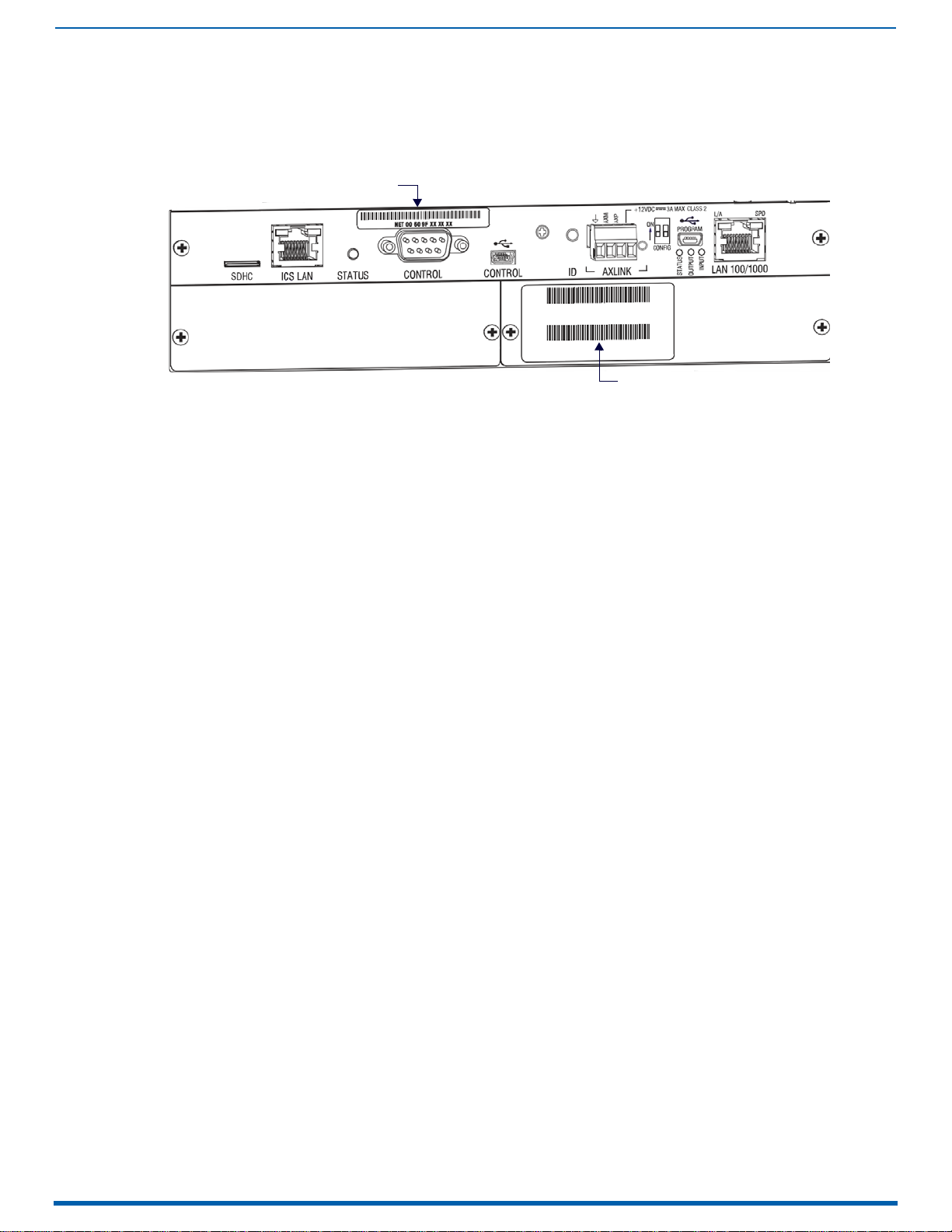
44
Enova Digital Media Switchers - Hardware Reference Manual
Installation and Setup
MAC Address
Serial Number
DGX Enclosure MAC Address / Serial Number
Installation and Setup
FIG. 13
NOTE:
reference.
DGX Enclosures rear view (CPU/Control board) - MAC Address and Serial Number decals
The MAC address for the system is located directly above the Control (DB-9 serial) port on the CPU.
The serial number is normally located on the rear of the enclosure on the left.
Before installation, record the serial number for the enclosure (and for each module and/or wallplate as applicable) for future
DXLink Fiber Boards
IMPORTANT: No user serviceable parts are included inside Enova DGX Switchers; service should only be done by qualified
personnel.
IMPORTANT: If the Enova DGX Switcher contains Enova DGX DXLink Fiber Boards, be sure to read all of the safety
information for laser products in this chapter and in the DXLink Fiber Boards chapter.
Safety Recommendations for Laser Products
WARNING: DXLink Fiber units use laser transceivers, which are Class 1 Eye Safe per IEC 60825-1/CDRH requirements. While the
Class 1 category indicates that the invisible laser used is safe, always avoid direct eye exposure when using any optical fiber
products (see the OSHA directive on page 135).
CAUTION:
hazardous radiation exposure.
Exercise caution when installing Enova DGX DXLink Fiber products to avoid direct eye exposure to invisible laser radiation.
Follow the recommendations below whenever installing or working with fiber products.
Use of controls or adjustments or performance of procedures other than those specified herein may result in
Be sure to apply the power only after all the fiber connections are made and no fiber ends are exposed.
Do not remove dust plugs from fiber connectors or the dust caps from the fiber cables until establishing
connections; avoid direct eye exposure.
Make sure all cables, including fiber cables, are correctly connected and/or terminated.
Before you unplug a fiber cable on an input board, disconnect the power on the transmitter that is connected to
the input.
Before you unplug a fiber cable on an output board, disconnect the switch for that output connector.
General Hazard Precautions
IMPORTANT: DXLink twisted pair cable runs for DXLink e quipment shall only be run within a common building. "Common
building" is defined as: Where the walls of the structure(s) are physically connected and the structure(s) share a single
ground reference.
Elevated Operating Temperature
The maximum rated ambient temperature for the Enova DGX Switcher is 104° F (40° C).
All equipment should be installed in an environment compatible with the manufacturer’s maximum rated ambient
temperature. In a closed or multi-unit rack assembly, the operating ambient temperature of the rack environment may
be greater than the ambient room temperature.
Airflow Restriction
Enova DGX Switchers are designed to adequately dissipate the heat they produce under normal operating conditions;
however, this design is defeated if high heat producing equipment is placed directly above or below an enclosure.
Page 45

Installation and Setup
45
Enova Digital Media Switchers - Hardware Reference Manual
CAUTION:
The system requires a minimum of one empty rack unit above and below (three empty rack units are recommend ed).
Verify that the openings on the top and sides of the enclosure are not blocked and do not
To prevent overheating, avoid placing high heat producing equipment directly above or below the enclosure.
have restricted air flow.
Mechanical (Rack) Loading
When installing equipment in a rack, distribute the weight to avoid uneven mechanical loading. Note that fully loaded,
the Enova DGX 800 weighs approximately 35 pounds (15.9 kg), the Enova DGX 1600 weighs approximately 55 pounds
(24.95 kg), the Enova DGX 3200 weighs approximately 73 pounds (33.1 kg), and the Enova DGX 6400 weighs
approximately 150 pounds (68.0 kg).
Circuit Overloading
When connecting the equipment to the supply circuits, be aware of the effect that overloading the circuits might have
on over-current protection and supply wiring.
Reliable Earthing (Grounding)
Reliable earthing of rack-mounted equipment should be maintained. If not using a direct connection to the branch
circuit (e.g., plugging into a power strip), pay particular attention to supply connections.
CAUTION:
After powering up the enclosure, apply power to the source and destination devices.
We strongly recommend attaching all of the power cords to a surge protector and/or an AC line conditioner.
Site Recommendations
Environment
Choose a clean, dust free, (preferably) air-conditioned location.
Avoid areas with direct sunlight, heat sources, or high levels of EMI (Electromagnetic Interference).
Chassis Accessibility
Make sure the front and rear panels of the enclosure are accessible, so that you can monitor the Power indicator LED on
the front and the other LED indicators on the rear. Leaving adequate clearance at the rear will also allow for easier
cabling and service.
Power
Attach all power cords to a surge protector (20 A) and/or an AC line conditioner.
The source’s electrical outlet should be installed near the router, easily accessible, and properly grounded. Power
should come from a building branch circuit. We strongly recommend using a dedicated line for the system’s
power. Use a minimum breaker current rating of 20 A for 110 V or 10 A for 230 V.
To avoid an overload, note the power consumption rating of all equipment connected to the circuit breaker
before applying power.
System Setup with Transmitters and Receivers
The following three sections cover system setup options for Enova DGX boards and their compatible TXs and RXs. The
following general statements apply to all three sections:
In each section’s table where "Any input board" or "Any output board" is shown, check in the specific board’s
chapter to determine whether or not a transmitter or receiver is required.
The transmitters and receivers mentioned in each section can be used as a standalone pair (end-to-end solution).
For additional information, see the applicable manual for the modules/units.
CAUTION:
Options for System Setup with DXLink Twisted Pair
The following table contains the options in an Enova DGX Switcher for using DXLink Twisted Pair Input and Output Boards in
conjunction with DXLink Twisted Pair Transmitters and Receivers:
System Setup Options - Enova DGX Boards with DXLink Modules/Wallplates
DXLink Module/Wallplate Enova DGX Input Board Enova DGX Output Board DXLink Module
Multi-Format TX Module → DXLink Twisted Pair → DXLink Twisted Pair → HDMI RX Module
Multi-Format TX Module
Multi-Format Wallplate TX
Multi-Format Wallplate TX
Decor Wallplate TX
Decor Wallplate TX
Not Applicable Any input board
A typical system setup for a source and destination is illustrated on page 116 and shows an Enova DGX 1600 with DXLink
Twisted Pair Boards used in conjunction with DXLink Twisted Pair Transmitters and Receivers.
NOTE: Solecis Digital Switchers have a DXLink Twisted Pair output port that optionally provides source point switching and
distance transmission to an Enova DGX DXLink Twisted Pair Input Board for hub-style or campus-wide distribution.
If you plan to connect switching systems via their DXLink ports, be sure to read the information on page 119.
→ DXLink Twisted Pair → Any output board → Not applicable
→ DXLink Twisted Pair → DXLink Twisted Pair → HDMI RX Module
→ DXLink Twisted Pair → Any output board → Not applicable
→ DXLink Twisted Pair → DXLink Twisted Pair → HDMI RX Module
→ DXLink Twisted Pair → Any output board → Not applicable
→ DXLink Twisted Pair → HDMI RX Module
Page 46

Installation and Setup
46
Enova Digital Media Switchers - Hardware Reference Manual
IMPORTANT: Before connecting a Solecis Digital Switcher to a DXLink Twisted Pair Input Board in an Enova DGX 100 Series
Digital Media Switcher, both the Solecis unit and all DXLink Twisted Pair boards must be upgraded with the latest available
firmware versions. Solecis units must
be upgraded before connecting a unit to an upgraded input board.
Options for System Setup with DXLink Twisted Pair 4K
The following table contains the options in an Enova DGX Switcher for using DXLink Twisted Pair 4K Input and Output
Boards in conjunction with DXLink Twisted Pair 4K Transmitters and Receivers:
System Setup Options - Enova DGX Boards with DXLink Modules/Wallplates
DXLink Wallplate Enova DGX Input Board Enova DGX Output Board DXLink Module
HDMI 4K Decor Wallplate TX → DXLink Twisted Pair → DXLink Twisted Pair → HDMI 4K RX Module
HDMI 4K Decor Wallplate TX
Not Applicable Any input board
NOTE: Additional compatibility is available between DXLink Twisted Pair 4K and DXLink Twisted Pair equipment (see the
DXLink Twisted Pair 4K Transmitters & Receivers Hardware Reference Manual).
→ DXLink Twisted Pair → Any output board → Not applicable
→ DXLink Twisted Pair → HDMI 4K RX Module
Options for System Setup with DXLink Fiber
The following table contains the options for using DXLink Fiber Input and Output Boards in conjunction with DXLink Fiber TXs
and RXs in an Enova DGX Digital Media Switcher. The input/output boards and TX/RX units can be either Duplex or
Simplex, as long as the model types match (multimode to multimode and single mode to single mode).
IMPORTANT: Compatibility between hardware requires matching model types: multimode to multimode and single mode
to single mode.
System Setup Options - Enova DGX Boards with DXLink Fiber
DXLink Fiber TX DXLink Fiber Input Board DXLink Fiber Output Board DXLink Fiber RX
Multi-Format MM Fiber TX → Multimode Fiber → Multimode Fiber → HDMI MM Fiber RX
Multi-Format MM Fiber TX
Multi-Format MM Fiber TX
Multi-Format SM Fiber TX
Multi-Format SM Fiber TX
Multi-Format SM Fiber TX
Not Applicable Any input board
Not Applicable Any input board
→ Multimode Fiber → Single Mode Fiber → HDMI SM Fiber RX
→ Multimode Fiber → Any output board → Not applicable
→ Single Mode Fiber → Single Mode Fiber → HDMI SM Fiber RX
→ Single Mode Fiber → Multimode Fiber → HDMI MM Fiber RX
→ Single Mode Fiber → Any output board → Not applicable
→ Multimode Fiber → HDMI MM Fiber RX
→ Single Mode Fiber → HDMI SM Fiber RX
NOTE: A typical system setup for a source and destination is illustrated on FIG. 53 on page 139.
Unpacking
Enova DGX Switchers are shipped with one enclosure per shipping box. The invoice is sent separately; a packing slip is
attached to the outside of each box.
Each box contains the following items:
Enova DGX 100 Series Digital Media Switcher
US power cords (if shipped within the US): Two provided with the DGX 800/1600/3200, four are provided for the
Enova DGX 6400
Other enclosure related products as needed
NOTE: For orders comprising multiple enclosures, the shipping boxes are marked as "Chassis __ of __," where the first blank
is the box number and the second blank is the total number of boxes in the shipment.
Unpacking Tips
Before fully unpacking the enclosure, inspect the shipping box for any signs of damage. If a box is partially crushed
or any sides have been broken open, notify the shipping agency immediately and contact your AMX
representative (see the warranty at www.amx.com
Once unpacking is complete, closely check the physical condition of the enclosure.
Collect all documentation.
NOTE: Please save the original shipping container and packing materials. AMX is not responsible for damage caused by
insufficient packing during return shipment to the factory. Shipping boxes are available; contact your AMX representative
for details.
).
Page 47

Installation and Setup
47
Enova Digital Media Switchers - Hardware Reference Manual
Install in rack.
Attach first two video input and output cables.
If applicable, install appropriate TXs and RXs.
If applicable, wire first two connectors on audio board(s).
If applicable - attach cable management bars for
DXLink Fiber Boards.
Establish connection from integrated Master to public
LAN via LAN 100/1000 port on CPU.
Apply power to enclosure(s) and then to system devices.
Launch System Configuration interface via browser
on PC connected to public LAN.
Execute a test switch.
Attach remaining video input and output cables.
If applicable, install remaining appropriate TXs and RXs.
If applicable, wire connectors on audio board(s).
If the system contains Audio Insert/Extract
Boards, they must be removed from the
system and the DIP switches on the
boards must be set to either insert or
extract audio according to system
requirements (see page 186).
If applicable - remove AIE Audio Boards, set DIP
switches to insert or extract, and re-install in enclosure.
DXLink twisted pair cable runs for DXLink
Input and Output Boards are only to be
run within a common building.
("Common building" refers a building
where the walls of the structure(s) are
physically connected and the structure(s)
share a single ground reference.
IMPORTANT!
IMPORTANT!
Rack Installation and System Setup
Enova DGX 100 Series Switchers can be mounted in a standard EIA 19 in. (48.26 cm) rack.
Required Items
Enclosure
Enova DGX 6400 only – two rack mounting handles (provided)
Standard EIA 19 in. (48.26 cm) rack
Screwdriver
Screws that fit your rack for mounting the enclosure
Power cords (provided, if shipped within the US)
Surge-protector – highly recommended
Optional Items
PC or laptop computer with a null modem cable for communication with the enclosure via the RS-232 serial port
Recommendations
Write the serial numbers (normally located on rear of enclosure) in an easily accessible location before installing
the enclosure in a rack.
Use earth-grounded power cords and equipment with an Enova DGX Switcher.
Attach all power cords to a single surge protector and/or an AC line conditioner.
Apply power to the Enova DGX Switcher before applying power to its source and destination devices.
Installation Procedure
A flow chart showing the installation sequence is in FIG. 14. The procedure below the chart provides general steps with
references to detailed information found in later sections of the manual.
CAUTION:
below the enclosure. The system requires a minimum of one empty rack unit above and below (three empty rack units are
FIG. 14
Installation Procedure
To prevent overheating and airflow restriction, avoid placing high heat producing equipment directly above or
recommended). Verify that the openings on the top and sides of the enclosure are not blocked and do not have
restricted air flow.
Page 48

Installation and Setup
48
Enova Digital Media Switchers - Hardware Reference Manual
Rack-Mounting Enova DGX 100 Series Enclosures
Rack-Mounting DGX 6400 Enclosures
The DGX 6400 Enclosure come with
CAUTION:
1. While the shipping box containing the enclosure is still on the pallet, cut loose and remove the outer straps.
2. Remove the cardboard tray from the top of the reusable shipping box. Note that the shipping box is mounted on
3. Lift the shipping box off of the pallet.
4. Unlock the four latches on the two sides of the shipping box.
5. Lift the top of the shipping box straight up and over the Enova DGX 6400 and set aside.
6. Attach the two provided Lifting Handles, using either the front or rear position as indicated in FIG. 15. Be sure to
The Enova DGX 6400 weighs approximately 150 lb (68 kg) for a fully loaded enclosure.
Installation of the DGX 6400 requires a minimum of two people, we recommend using three people for lifting and
positioning the enclosure.
Ensure all parties involved in lifting the shipping box are prepared and follow local requirements as necessary for
the task (e.g., wearing proper lifting attire, number of lifters, etc).
wheels.
tighten down all four screws securely on both handles.
FIG. 15
7. Using the bottom of the shipping box, roll the enclosure into position.
8. Select a position in the rack for the enclosure that is accessible and does not restrict airflow.
9. Lift onto a temporary shelf (or some other type of support) in the rack.
10. DGX-6400 only - Align as closely as possible and then remove the lifting handles.
11. Lift into position and install the rack ear screws (see FIG. 16 on page 49).
DGX-6400 Lifting Handle Position Options
CAUTION:
Lifting Handles to maneuver it. Use a temporary shelf for support.
Do not use the board extractor handles to lift the enclosure or to maneuver it into place. Use the provided
Page 49

49
Enova Digital Media Switchers - Hardware Reference Manual
Rack-Mounting DGX 800/1600/3200 Enclosures
Align screws with
mounting holes in rack
CAUTION:
people.
1. Select a position in the rack for the enclosure that is accessible and does not restrict airflow.
2. Position the enclosure in the rack, and install the rack ear screws on each side (FIG. 16).
Installation of DGX 800/1600/3200 Enclosures requires a minimum of two people; we recommend using three
Installation and Setup
FIG. 16
Rack-Mounting DGX 800/1600/3200 Series Enclosures
Installing Boards, Connecting Devices and Powering up the DGX Enclosure
1. Audio Insert/Extract Boards only – Remove the boards (see FIG. 89 on page 179) and set the DIP switches to either
insert or extract audio (see page 178). This is the only mechanism for configuring the insert/extract functionality.
CAUTION:
On systems with DXLink Fiber Input and Output Boards, use the provided cable management bars (or
some other type of cable management system) to avoid damage to the fiber cables.
2. DXLink Fiber Boards – Attach the provided cable management bars to the input and output boards (see page 50).
3. Attach only the first two source and destination devices.
If connecting devices to DXLink Twisted Pair Boards, the boards require DXLink Transmitters and Receivers. Install
the Transmitters and Receivers between the first two source and destination devices and the DXLink Boards (see
"System Setup with DXLink Transmitters and Receivers" on page 116 and the product’s documentation).
If connecting devices to DXLink Fiber Boards, the boards require DXLink Fiber Transmitters and Receivers. Install the
Transmitters and Receivers between the first two source and destination devices and the DXLink Fiber Boards (see
"System Setup with DXLink Fiber, Duplex and Simplex Units" on page 139 and the product’s documentation).
If wiring devices to Dante Audio Switching Boards, see page 150.
If wiring devices to Audio Switching Boards, see page 164.
If wiring devices to Audio Insert/Extract Boards, see page 175.
4. Attach power cords to all power receptacles on the enclosure, then turn on the entire system (see page 63).
CAUTION:
Use a surge protector and/or an AC line conditioner.
NOTE: If an Enova DGX 3200 system contains DXLink Twisted Pair Boards, calculate the power draw for the system to
maintain redundancy of power supplies in enclosure and determine how many DXLink Twisted Pair TXs and RXs can
be powered via the switcher. See the Power Budget Planning for Systems with DXLink Twisted Pair Boards section on
page 63 for details.
5. Launch the System Configuration interface via a browser on a PC or tablet (see page 52).
NOTE: The default Username for the interface is "administrator" and the default Password is "password". After initial
setup, defaults should be changed to ensure system security.
6. Disconnect the factory default switch and execute a test switch to make sure system is working properly (see
page 58).
7. When the test switch works correctly, attach the remaining source and destination devices and any additional
required transmitters and receivers. If applicable, wire remaining connectors on Audio Switching Boards or Audio
Insert/Extract Board(s).
Special Information for Audio Expansion Boards
Three types of audio expansion boards are available: Dante Audio Switching Boards (ASB-DAN), Audio Switching Boards
(ASB) and Audio Insert/Extract (AIE) Boards.
For Dante Audio Switching Board information, see page 150.
For Audio Switching Board information, see page 164. If the system contains AIE Boards, the connector default
settings may need to be changed for desired audio insertion or extraction functionality.
For AIE Board information, see page 175.
Page 50

Installation and Setup
50
Enova Digital Media Switchers - Hardware Reference Manual
Connector Numbering Plate
IMPORTANT!
Do not over-tighten
the installation screws
Fasten Cable Management
Bar with two screws on one
end, and one on the other
Tie cable to the Cable Management Bar far
enough from the connector to allow for the
manufacturers recommended bend radius
Cable Management Bar
Input board
Output Board
Note that the orientation of Cable Management Bar is reversed from input to output board
Installation Options
Additional installation tasks may include the following:
Attaching an AxLink Device – page 59
Using the ID Pushbutton – page 60
Setting PRD Mode – page 61
Establishing Telnet connection with the CPU – page 256
Establishing external serial control – page 313
Attaching Cable Management Bars
If the enclosure has DXLink Fiber Input and Output Boards installed, Cable Management Bars are provided.
CAUTION:
Do not severely bend or kink any type of fiber cable. Irreversible damage can occur. Refer to the physical
limitations (bend radius) specified for the cable by the manufacturer.
Cable management bars are not to be used as handles to remove or install boards.
1. Enova DGX 3200 only – Loosen the two captive screws that hold the Connector Numbering Plate at the top of the
connectors (FIG. 17). Remove the Connector Numbering Plate and set aside.
FIG. 17
Connector Numbering Plate (DGX 3200)
2. Align the two screw holes on the end of the Cable Management Bar with the two screw holes on the end of the
board. Note the position of the long part of the bar in relation to screw holes (FIG. 18, FIG. 19):
FIG. 18 Cable Management Bars - Enova DGX 3200
FIG. 19 Cable Management Bars - Enova DGX 800/1600/6400
3. Insert and tighten the two screws at the end of the Cable Management Bar.
4. Align, insert, and tighten the single screw at the other end of the Cable Management Bar.
5. Tie the cable to the cable management bar far enough from the connector to maintain the manufacturer’s
recommended bend radius.
6. Enova DGX 3200 only – Replace the Connector Numbering Plate that was removed in Step 1.
Page 51

Installation and Setup
51
Enova Digital Media Switchers - Hardware Reference Manual
Attaching Video Input and Output Cables
Input and output connectors are the attachment points for source and destination devices that connect to the system.
Enova DGX 800
Viewed from the rear of the enclosure, the Enova DGX 800/1600 input boards (for attaching sources) are on the left, and
the output boards (for attaching destinations) are on the right.
DGX 800 enclosures have 4 horizontal board slots (2 slots each for the input and the output boards, with 4
connectors per board), allowing for a maximum configuration of 8x8. See FIG. 2 on page 35.
Input and output channel numbers correspond to the connectors and are located between the input and output
boards. For inputs, numbering is consecutive from left to right on each board from the top board to the bottom
one; outputs start over at "1" and follow the same pattern.
Enova DGX 1600
Viewed from the rear of the enclosure, the Enova DGX 800/1600 input boards (for attaching sources) are on the left, and
the output boards (for attaching destinations) are on the right.
DGX 1600 Enclosures have 8 horizontal board slots (4 slots each for the input and the output boards, with 4
connectors per board), allowing for a maximum configuration of 16x16. See FIG. 5 on page 37.
Input and output channel numbers correspond to the connectors and are located between the input and output
boards. For inputs, numbering is consecutive from left to right on each board from the top board to the bottom
one; outputs start over at "1" and follow the same pattern.
Enova DGX 3200
Viewed from the rear of the enclosure, the Enova DGX 3200 input boards (for attaching sources) are on the left, and the
output boards (for attaching destinations) are on the right. See FIG. 8 on page 39.
DGX 3200 Enclosures have 16 vertical board slots (8 slots each for the input and the output boards, with 4
connectors per board), allowing for a maximum configuration of 32x32.
Input and output channel numbers correspond to the connectors and are located on the numbering plate (metal
strip) directly above the boards. For inputs, numbering is consecutive from top to bottom on each board from the
left board to right one; outputs start over at "1" and follow the same pattern.
Enova DGX 6400
The Enova DGX 6400 has input boards at the top of the enclosure’s rear and output boards below. See FIG. 11 on
page 42.
DGX 6400 Enclosures have 32 horizontal board slots (16 slots each for the input and the output boards, with 4
connectors per board), allowing for a maximum configuration of 64x64.
Input and output channel numbers correspond to the connectors and are located in the middle of the enclosure
between boards on either side. For inputs, numbering is consecutive from left to right on each board from the top
input board on the left to the bottom input board on the left, continuing on the top input board on the right to the
bottom input board on the right. Outputs start over at "1" and follow the same pattern.
Cabling Specific Connector Types
For information on board connectors and cabling and specifications for specific types of connectors:
HDMI 4K60 Boards – page 81
HDMI Boards – page 95
DVI Boards – page 106
DXLink Twisted Pair Boards – page 112
DXLink Twisted Pair 4K Boards – page 123
DXLink Fiber Boards – page 134
Input and Output Signal Cables
CAUTION:
Twisted Pair Boards, and DXLink Fiber Boards), be sure to read the information on page 125 (DXLink Twisted Pair 4K), on
page 118 (DXLink Twisted Pair), and on page 144 (DXLink Fiber).
If using cable management bars, install them before attaching the cables (see page 50).
Before connecting all of the input and output cables and wires, attach only the ones for the first two sources and
destinations (and any applicable transmitters and receivers). Complete the remaining installation tasks (applying power
and any system setup though the System Configuration interface), and then disconnect the factory default switch and
execute a test switch (see page 58). When the test switch is successful, attach the remaining input and output cables and
wires.
If you are connecting switching systems via their DXLink ports (applies to DXLink Twisted Pair 4K Boards, DXLink
Page 52

Installation and Setup
52
Enova Digital Media Switchers - Hardware Reference Manual
DGX 3200 Enclosure
LAN 100/1000 Port (DGX enclosure connected to PCs via LAN)
Wiring Audio Inputs and Outputs
Enova DGX Switchers can include the following audio expansion boards: Dante Audio Switching Boards (ASB-DAN), Audio
Switching Boards (ASB) or Audio Insert/Extract (AIE) Boards. Audio expansion boards work in conjunction with HDMI, 4K
HDMI, DVI, DXLink Twisted Pair 4K, DXLink Twisted Pair, and DXLink Fiber Boards. The inputs and outputs are configured on a
per connector basis to route audio into, out of, or through the system.
CAUTION:
Do not install mixed types of expansion boards in the same enclosure. If two types of boards are present, the audio
subsystem is disabled.
IMPORTANT: Audio Insert/Extract Boards Only - Setting the DIP switches is the only mechanism for configuring insert/extract
functionality on the Audio Insert/Extract Board. Therefore, setting the switches (which requires removal of the board from
the enclosure) needs to be done at the time of installation setup.
For information on board connectors and wiring and specifications for specific types of connectors:
Refer to the following figures for the locations of the Expansion Board Slots on each DGX 100 Series Enclosure:
Audio Switching Boards, Dante Audio Switching Boards, and Audio Insert/Extract Boards are not compatible.
Dante Audio Switching Boards (ASB-DAN) – page 164
Audio Switching Boards (ASB) – page 164
Audio Insert/Extract Boards (AIE) – page 175
DGX-800: FIG. 2 on page 35
DGX-1600: FIG. 5 on page 37
DGX-3200: FIG. 8 on page 39
DGX-6400: FIG. 11 on page 42
System Setup for Using the Integrated NetLinx NX Master
The Enova DGX 100 Series Switcher has an integrated NetLinx NX Central Control Processor (Master) that establishes its
public LAN (Local Area Network) connection through the LAN 100/1000 port on the CPU. The Master provides a System
Configuration interface that allows you to make various configuration settings via a web browser on any PC connected
to the public LAN. The NX Master’s on-board System Configuration interface delivers HTML pages for setting up the system
plus dedicated Switching, Configuration, and Status pages which allow for remote control and monitoring of an Enova
DGX Switcher using PC-based Internet browsing software.
IMPORTANT: The Enova DGX Switcher uses DHCP to retrieve its IP address by default. The integrated Master’s IP address is
available via the control panel at Setup Options/Master Info/IP Address.
The enclosure must be connected to a LAN in order to get an IP address from a DHCP server. After the network assigns a
DHCP IP address, a static IP address can be assigned in its place.
IMPORTANT: Although it is also possible to provide access from outside a LAN via the Internet, security issues for your LAN
environment must be taken into account (contact your Network Administrator).
System Setup Overview
IMPORTANT: The Enova DGX Switcher uses DHCP by default.
The LAN 100/1000 (Ethernet) port provides functionality for the following protocols: FTP, SSH, Telnet, HTTP, HTTPS/SSL, and
ICSP (for protocol descriptions and standard port numbers used, see the table on page 54). This port is connected to a
public LAN. By default, the integrated Master will receive an IP address from the LAN it connects with (via DHCP). Once
the System Configuration interface has been launched and a test switch has been completed, it will be possible to
reconfigure the integrated Master’s LAN 100/1000 port IP setting from DHCP to Static IP (see page 201).
FIG. 20 shows a DGX 3200 connected to a LAN via the LAN 100/1000 port. Both computers in the figure have access to the
enclosure via the LAN.
FIG. 20
CAUTION:
modules), page 119 (DXLink Twisted Pair modules), and/or see page 134 (DXLink Fiber modules).
Enova DGX 3200 connected via a LAN to two PCs
Be careful not to create a network (Ethernet) loop. To avoid doing so, see page 130 (DXLink Twisted Pair 4K
Page 53

Installation and Setup
53
Enova Digital Media Switchers - Hardware Reference Manual
T568A Pairing
connections for Ethernet RJ-45
connector/cable per T568A
RJ-45 Ports
The Enova Series CPU has two RJ-45 ports: the ICS LAN port on the left and the LAN 100/1000 port on the right. The ICS LAN
port acts as a DHCP server (private LAN) and the LAN 100/1000 port acts as a DHCP client (public LAN) with each port on
a separate network.
CAUTION:
on the public LAN (LAN 100/1000 port).
Both of the RJ-45 ports indicate the same type of LED information and use the same pinouts for cabling.
RJ-45 Port LEDs
The two small rectangular LEDs on the RJ-45 connector indicate the following:
ICS LAN 10/100 and LAN 100/1000 Indicator LEDs
In order to avoid a Network Loop, do not connect any device on the private LAN (ICS LAN port) to any branch
Green L/A LED: On – Link is active (when the Ethernet cable is connected and terminated correctly)
Yellow SPD LED: On – receiving or transmitting LAN data packets
FIG. 21
ICS LAN 10/100 and LAN 100/1000 port LED indicators
Cable Requirements and Pinouts
RJ-45 link cable (either crossover or straight-through) – required to connect an Enova DGX Switcher to the public LAN.
NOTE: Cable can be wired to either T568A (see below) or T568B (on the next page), as long as the wiring is consistent on
both ends.
T568A
The following table lists the pinouts, signals, and pairing for the Ethernet connector when wired for straight-through cable
according to T568A.
T568A
Pin Signals Connections Pairing Color
1 TX+ 1--------1 1--------2 Green - White
2 TX- 2--------2 Green
3 RX+ 3--------3 3--------6 Orange - White
4 No connection 4--------4 Blue
5 No connection 5--------5 Blue - White
6 RX- 6--------6 Orange
7 No connection 7--------7 Brown - White
8 No connection 8--------8 Brown
Page 54

Installation and Setup
54
Enova Digital Media Switchers - Hardware Reference Manual
T568B Pairing
T568B
The following table lists the pinouts, signals, and pairing for the Ethernet connector when wired for straight-through cable
according to T568B.
T568B
Pin Signals Connections Pairing Color
1 TX+ 1--------1 1--------2 Orange - White
2 TX- 2--------2 Orange
3 RX+ 3--------3 3--------6 Green - White
4 No connection 4--------4 Blue
5 No connection 5--------5 Blue - White
6 RX- 6--------6 Green
7 No connection 7--------7 Brown - White
8 No connection 8--------8 Brown
connections for Ethernet RJ-45
connector/cable per T568B
ICS LAN 10/100 Port
The ICS LAN 10/100 port on the left-hand side of the CPU is the access point for communication with devices on the
private
(ICS LAN) network. The port has a built-in DHCP server which serves IP addresses for the private LAN to endpoint devices.
LAN 100/1000 Port
The LAN 100/1000 (Ethernet) port, which provides the connection from the integrated NetLinx NX Master to a public LAN,
is located on the rear of the enclosure on the right-hand side of the CPU. The port handles Ethernet 10/100/1000
connections for 1000 Mbps (megabits per second), 100 Mbps, and 10 Mbps. This connection is compatible with most
Ethernet based LANs.
IMPORTANT: Because the LAN 100/1000 port is the single, shared connection to the public LAN, a Gigabit (1000 Mbps) LAN
connection between the network and the Enova DGX Switcher’s LAN 100/1000 port is strongly recommended. Lower
speed connections may result in inferior performance of the embedded Ethernet network.
CAUTION:
LAN) with each port on a separate network. In order to avoid a Network Loop, do not connect any device on one
network to any branch on the other network.
The ICS LAN port acts as a DHCP server (private LAN) and the LAN 100/1000 port acts as a DHCP client (public
IP Protocols Used by the Enova DGX Integrated Controller
IP Protocols Used by the Integrated Controller
Protocol Description Standard Port #
FTP The integrated Master has a built-in FTP server 21/20 (TCP)
SSH The SSH port functions using the same interface as Telnet but over a secure shell where it uses SSL as
Telnet The NetLinx Telnet server provides a mechanism to configure and diagnose a NetLinx system. For
HTTP The integrated Master has a built-in web server that complies with the HTTP 1.0 specification and
HTTPS/SSL This port is used by a web browser for secure communication between the web server UI and the
ICSP The port is used for peer-to-peer protocol for both Master-to-Master and Master-to-device
a mechanism to configure and diagnose a NetLinx system. This port value is used for secure Telnet
communication.
Note: Only SSH version 2 is supported.
maximum flexibility, the Master can be configured to use a different port than 23 or disable Telnet
completely from either Telnet or the Program port on the rear of the Enova DGX Switcher. Once
disabled, the only way to enable Telnet again is from the Program port.
supports all of the required features of HTTP v1.1. This port is used for unsecured HTTP Internet
communication between the web browser’s UI and the integrated Master.
integrated Master. This port is also used for simultaneous encryption of this data, using the SSL
certificate information on the Master as a key.
communications. This type of communication is used by various AMX products for communication
among themselves (see page 204).
Note: The integrated Master can only be configured to use Port 1319, and the ICSP cannot be
disabled.
22 (TCP)
23 (TCP)
80 (TCP)
443 (TCP)
1319 (UDP/TCP)
Page 55

Installation and Setup
55
Enova Digital Media Switchers - Hardware Reference Manual
Avoiding Network (Ethernet) Loops
Only one connection to the Public LAN is permitted within a switching system with DXLink support.
NOTE: This applies to systems with DXLink Twisted Pair and/or DXLink Fiber Boards.
Network loops must be avoided. A network loop is created when the enclosure and one or more DXLink Modules or
Wallplates within the system are connected to the same Public LAN as the Enova DGX. The Enova DGX Switcher does not
support STP (Spanning Tree Protocol).
IMPORTANT: If DXLink Twisted Pair units are used in conjunction with DXLink Twisted Pair 4K units or DXLink Fiber uni t s, all
units’ guidelines must
FIG. 22 indicates a network loop created when an Enova DGX 1600 was connected to a Public LAN and one of its DXLink
Transmitters was connected to the same LAN. In this case, the DXLink Transmitter needs to be disconnected from the LAN.
The same problem would also occur if an enclosure and one (or more) of its DXLink Receivers were connected to a
common Public LAN.
be followed.
FIG. 22
IMPORTANT: If the system has DXLink input and output connectors in use, the LAN 100/1000 port should use a connection
speed of 1000 Mbps.
FIG. 23 indicates a network loop created when an Enova DGX 1600 was connected to a Public LAN and one of its DXLink
Receivers was connected to the same LAN. In this case, the DXLink Receiver needs to be disconnected from the LAN:
FIG. 23 Avoid Network Loops - DXLink Receiver
IMPORTANT: If DXLink Twisted Pair 4K units are used in conjunction with DXLink Twisted Pair or DXLink Fiber units, all units’
guidelines must
Avoid network loops - DXLink TX
be followed.
Page 56

Installation and Setup
56
Enova Digital Media Switchers - Hardware Reference Manual
Cable to LAN hub or switch
LAN 100/1000 (RJ-45) connector
FIG. 24 indicates a network loop created when an Enova DGX 1600 was connected to a Public LAN and one of its DXLink
Fiber, Duplex Transmitters in Bidirectional Mode was connected to the same Public LAN as the Enova DGX. In this case, the
DXLink Fiber, Duplex Transmitter needs to be disconnected from the LAN.
The same problem would also occur if an enclosure and one (or more) of its DXLink Fiber, Duplex Receivers were
connected to a common Public LAN.
FIG. 24
IMPORTANT: For Duplex hardware in Bidirectional Mode connected to an Enova Digital Media Switcher, we recommend
connecting the switcher to the network for all network connection needs. Network connections via the switcher are faster
and more reliable. Never connect
network loops.
CAUTION:
network loops before connecting units.
Avoid network loops
both a TX and RX, a TX and switcher, or a switcher and RX to the same network: Avoid
If you have questions or concerns about network setup, consult with your network administrator about avoiding
Connecting an Enova DGX to a Public LAN via the LAN 100/1000 Port
IMPORTANT: In order to use the on-board System Configuration interface, the Enova DGX Switcher must establish an
active connection to a public LAN. Do not connect the LAN 100/1000 port on the Enova DGX Switcher to a PC; it will not
work.
1. Insert one end of the RJ-45 link cable into the LAN 100/1000 port on the enclosure.
2. Connect the other end of the RJ-45 link cable to a LAN hub or switch. The network automatically assigns a DHCP IP
address (the assigned IP address can be changed to a static IP address).
FIG. 25 RJ-45 link cable connected to LAN 100/1000 port
3. Check the indicator LEDs for the LAN 100/1000 connector (see page 53).
NOTE: When the connection is made, the DHCP server on the network will automatically assign an IP address. If you power
down and power back up, the DHCP server will reassign the IP address, which may or may not be the same address it
assigned before. To prevent the possibility of the IP address changing at power up, you can change the DHCP address to
a static IP address (see the NetLinx NX Central Controllers WebConsole & Programming Guide at www.amx.com
integrated Master’s IP address is available via the control panel at Setup Options/Master Info/IP Address.
Confirming Board Versions
Enova DGX enclosures and boards typically ship with the latest firmware available. If the firmware on any board installed
in the enclosure does not match the firmware version the enclosure expects, a firmware mismatch occurs. To resolve a
firmware mismatch, the latest available firmware .kit file (which contains firmware for both boards and enclosure) must be
sent to the enclosure.
1. Launch NetLinx Studio and connect to the DGX Master.
2. Open the OnLine Tree tab, right-click in the Workspace Bar field and select Refresh System Online Tree.
3. Expand the 5002 device and confirm compatible board versions (or mismatch).
4. If a mismatch is present, send the latest firmware .kit file to the enclosure.
NOTE: Instructions for sending a .kit file are located on page 203.
). The
Page 57

Installation and Setup
57
Enova Digital Media Switchers - Hardware Reference Manual
System Configuration Interface Setup
System Requirements
Minimum web browser requirements – Google Chrome v30, Internet Explorer v10, Firefox v24, Safari v6.0, Opera v24, or
other browser with substantial support for HTML5 features
NOTE: User experience may differ due to browser support for HTML5.
Setting up the system to use AMX’s System Configuration interface requires completing the following three items. Detailed
instructions for each item are given.
Determine the integrated Master’s IP address via the front Control Panel
Open a web browser on the PC. Note that the PC (or tablet) must be on the same LAN that the enclosure is
connected to via the LAN 100/1000 port.
Open the System Configuration interface
NOTE: Place source and destination devices within view until the test switch confirms correct routing behavior. Any
applicable modules/wallplates should be correctly installed and power must be applied to both the enclosure and
source and destination devices.
The steps below assume that the DGX is powered on and connected to the LAN via the LAN 100/1000 port (FIG. 25).
Logging On To the System Configuration Interface and Executing a Test Switch
NOTE: The System Co nfiguration interface can also be launched via NetLinx Studio (see page 209).
1. Determine the integrated Master’s IP address:
a. On the front Control Panel, locate Setup Options by scrolling with the Control Dial.
b. Press the Select key.
c. Locate IP Address by scrolling with the Control Dial.
d. Press the Select key to display the IP Address.
e. Record the IP address for use in Step 3.
2. On a PC or tablet, open a web browser that supports HTML5.
3. In the web browser’s address bar, enter the Enova DGX’s IP address and press Enter. The System Configuration
interface’s Home page appears in the browser.
IMPORTANT: The default Username for the interface is "administrator" and the default Password is "password". After initial
setup, defaults should be changed to ensure system security.
4. From the main menu bar at the top of the screen, select Switcher>Switching. The Switching page appears.
5. Disconnect the factory default switch (Input 1 routed to all Outputs):
a. Click Input 1.
b. Under outputs, select Deselect All.
c. Click Take.
6. Make sure the first two source devices and the first two destination devices are connected to the first two input and
output connectors (for specific board connector information and specifications, see the board chapter).
7. Route Input 1 to Output 2 (click Input 1, then Output 2, then click the Take button).
8. To verify the switch, click Input 1 again. Both the Input 1 and Output 2 buttons will turn blue and both selections will
appear in the Selected pane on the right.
9. Disconnect the test switch (click Output 2 and click Take) and finish the installation.
For System Configuration interface tips, see page 201.
NOTE: For instructions on executing a test switch via BCS Commands, see the "BCS (Basic Control Structure) Protocol
Programming Guide" at www.amx.com
Additional Setup Options
Audio Control and Signal Processing (see the following page)
Establish serial communication with a PC via the Program port (see page 58)
Attaching an AxLink device (see page 59)
Using the ID Pushbutton (see page 60)
Enable Program Run Disable (PRD) Mode (see page 61)
.
Page 58

Installation and Setup
58
Enova Digital Media Switchers - Hardware Reference Manual
PROGRAM Port LEDs
PROGRAM (USB) Port
Audio Control and Signal Processing Options
Audio Switching Boards (ASB)
The audio signal on Audio Switching Boards can be switched independently of the video or as embedded audio. These
boards also allow for digital signal processing (e.g., volume, equalizer, input gain) on every input and every output in the
enclosure. When using Audio Switching Boards, the Enova DGX 6400 requires two each of the input and output boards for
functionality. Both boards are provided as part of the compatible DGX6400-ASB Audio Switching Board Kit for the Enova
DGX 6400.
NOTE: The Audio Insert/Extract Board has no control options aside from the configuration of DIP switches. All switching of
audio is executed in conjunction with the switches executed on the corresponding input and output connectors (for
additional information, see the Audio Insert/Extract Board chapter on page 175).
System Configuration Interface
Switching audio outputs/inputs – page 185
Switching a down-mixed signal – page 188
Configuring audio outputs/inputs – page 131
ICSP Commands
Switching audio outputs/inputs – page 209
Digital Signal Processing audio commands – page 225
Control Panel
NOTE: Audio from Audio Switching Boards cannot be switched indepen dently from the Control Panel. When the audio
from the boards is embedded on a video signal, only volume, input gain, and mute can be applied from the Control
Panel.
Volume – page 75
Input gain – page 76
Mute – page 75
BCS Commands
Volume, input gain, and mute – See the BCS (Basic Control Structure) Protocol Programming Guide at
www.amx.com
.
Establishing Serial Communication with a PC via the Program Port
Program Port
The Enova DGX Switcher’s integrated NetLinx NX Master is equipped with a low-speed USB connection labeled "Program."
Use the provided USB mini-AB adapter cable (CA1090-541) to establish a connection between the Program port on the
enclosure and the PC’s USB port.
This connection provides serial-based communication between the integrated Master and NetLinx Studio. This port is
useful for getting and setting the system’s IP address (in NetLinx Studio, open Tools/Telnet Session and enter either GET IP
<D:P:S> or SET IP <D:P:S>, where D:P:S is Device:Port:System).
IMPORTANT: The Program port is not recommended for firmware updates or large file transfers. These more data-intensive
operations are better handled via the LAN 100/1000 port connection.
Cable Requirements
USB mini-AB adapter cable (provided) – required to connect an Enova DGX Switcher via its Program port to a PC.
Program Port LEDs – Modes and LED Blink Patterns
FIG. 26
Program Port LEDs
Page 59

Installation and Setup
59
Enova Digital Media Switchers - Hardware Reference Manual
AxLink LED
AxLink port
AXM = AxLink AXP = AxLink +
AxLink port on CPU AxLink port on AxLink device(top view)
GND
AXP-TX
AMX-RX
PWR
GND
AXP-TX
AMX-RX
PWR
(top view)
The following table lists the modes and the blink patterns for the Program port’s LED indicators which are associated with
each mode. These blink patterns are not evident until the unit is powered.
Modes and LED Blink Patterns
LEDs and Blink Patterns
Mode Description
OS Start Starting the operating system (OS). On On On
Boot Integrated Master is booting. On Off On
Contacting DHCP Server
Unknown DHCP Server Integrated Master could not find the DHCP server. Fast Blink Off Off
Downloading Boot
Firmware
No program running Either no program is loaded or the program is disabled. On Normal* Normal*
Normal Integrated Master is functioning normally.
Integrated Master is contacting a DHCP server for IP
configuration information.
Downloading Boot firmware to the integrated Master’s
flash memory.
cycle power during this process.
Do not
Status
(Green)
On Off Fast Blink
Fast Blink Fast Blink Fast Blink
1 blink per
second
Output
(Red)
On indicates
activity
Input
(Yellow)
On indicates
activity
* "Normal" is typically off. However, this state may change depending on external inputs.
Attaching an AxLink Device
The CPU board has an AxLink port and an adjacent AxLink LED on its right. The AxLink port is a 4-pin mini-Phoenix (female)
captive-wire connector. This port allows the integrated Master to support AMX AxLink devices.
The AxLink port can be used to supply power to downstream AxLink-compatible devices as long as the power required
does not exceed 2 Amps .
FIG. 27 AxLink Connector and LED
AxLink LED
A green AxLink LED indicates AxLink data activity. "Off" indicates either no power or the Master is not functioning properly.
When the AxLink port is operating normally, LED blink patterns include:
1 blink per second – Normal operation.
3 blinks per second – AxLink bus error. Check all AxLink bus connections.
Using the AxLink Connector for Data and Power
To supply data and power to an AxLink compatible device, wire the AxLink connector as shown in FIG. 28:
FIG. 28 AxLink connector wiring diagram (direct data and power)
AxLink Device Numbering
For NetLinx programming purposes, each AxLink device must be assigned a unique number to locate that device on the
bus. The range for AxLink device numbers is 1-255. AMX best practices requires assigning device numbers in three groups:
Axcess Control Cards: 1 - 95
Axcess Bus Boxes: 96 - 127
Axcess Panels/Receivers: 128 - 255
NOTE: If you are familiar with binary, start at Step 3 and set the device’s DIP switch toggles accordingly (zero = all up;
255 = all down).
Page 60

Installation and Setup
60
Enova Digital Media Switchers - Hardware Reference Manual
ID Pushbutton
AxLink port
Setting an AxLink Device Address
1. Open NetLinx Studio and select Tools>DIP Switch. The DIP Switch 2.0 applet appears.
2. Enter the AxLink device number in the Device Number text box and note toggle positions. Close the applet.
3. On the bottom/side of the AxLink device, set the device’s DIP switch toggles to an appropriate device number
according to AMX best practices (see established ranges above).
4. Connect AxLink cables from the AxLink device to the AxLink port on the Enova DGX CPU.
5. In NetLinx Studio, select the OnLine Tree tab and refresh the OnLine Tree with the Enova DGX displayed. The AxLink
device appears as a device in the OnLine Tree.
AxLink Power Measurement and Control
The AxLink port on the CPU supports a SEND_COMMAND to turn on and off +12V power output on the port.
AXPWRON LOWER – turns on power output on port
AXPWROFF LOWER – turns off power output on port
These messages are always sent to port 1 of the 5001 control device (D:P:S = 5001:1:0) and return status comes from the
same port.
AxLink Port Diagnostics
The fault state can be queried using the SEND_COMMAND: GET AX FAULT (D:P:S = 5001:1:0).
The reply to normal operating status is: AX FAULT: NONE
The reply to a problem in operating status is: AX FAULT: BUS
Removing the problem should restore the fault state to NONE without intervention.
NOTE: Shorting the bus power does not cause a fault that GET AX FAULT can detect.
Using the ID Pushbutton
The ID Pushbutton for the integrated Master is located on the rear of the enclosure on the CPU board to the left of the
AxLink Port (FIG. 29):
FIG. 29
The ID Pushbutton can be used to perform three types of initial configuration settings:
NOTE: ID Pushbutton functions can also be implemented using Telnet commands (see the "WebConsole & Programming
Guide – NetLinx NX Central Controllers" at www.amx.com
ID Pushbutton
Toggle between DHCP (default) and static IP addressing (see below).
Reset the switcher to its factory default settings, which affects the settings but not the firmware version (page 60).
Restore the switcher to its factory firmware image, which affects both the firmware version and the settings
(page 61).
).
Toggling Be tween DHCP and Static IP Addressing
1. Verify that the Master is not currently booting.
2. Press and hold the ID Pushbutton for 10 seconds or longer.
3. Release to toggle between static and dynamic IP addressing. The Master will automatically reboot to complete the
process.
NOTE: The default static IP address is 192.168.1.2 with a 255.255.255.0 subnet mask.
Resetting the Factory Default Settings:
A reset of the Master to factory default settings includes the removal of all security settings and user files (including all
code and IRL files), resetting to DHCP, and loading an empty NetLinx program. Once reset, the Master will be effectively
in an out-of-box state.
1. Verify that the Master is currently booting.
NOTE: The Master is booting when the Program port Status and Input LEDs are ON (green and yellow respectively)
and the Output LED (red) is OFF.
2. During the boot process, press and hold the ID Pushbutton for 10 seconds or longer.
CAUTION:
firmware image on the Master.
3. Release to reset to the factory defaults.
Do not press longer than 10 seconds. Pressing the ID Pushbutton for 20 seconds restores the factory
Page 61

Installation and Setup
61
Enova Digital Media Switchers - Hardware Reference Manual
CONFIG DIP Switch
12
Restoring the Factory Firmware Image and Factory Default Settings
1. Verify that the Master is currently booting.
NOTE: The Master is booting when the Program port Status and Input LEDs are ON (green and yellow respectively)
and the Output LED (red) is OFF.
2. Press and hold the ID Pushbutton for 20 seconds or longer.
3. Release the pushbutton.
Program Run Disable (PRD) Mode
IMPORTANT: The information in this section is not applicable when the system is running under normal operating
conditions. The PRD mode should only be used if the resident NetLinx program is causing inadvertent communication
and/or control problems.
If necessary, use NetLinx Studio (v4.0 or later) to resolve communication and/or control problems with the resident NetLinx
program. PRD mode prevents the NetLinx program stored in the integrated Master from running during the Enova DGX
enclosure’s power-up.
PRD mode (ON) equates to a "SAFE" mode setting on a PC: it allows powering the unit, updating the firmware, and
downloading a new program, while circumventing any problems with a currently downloaded program.
Power must be cycled to the enclosure after activating/deactivating the PRD mode.
NOTE: DIP switch #2 m ust
Setting the Config DIP Switch To Place the Integrated Master in PRD Mode
NOTE: The DIP switch is mounted with the ON position at the top (as indicated by the arrow on the left).
1. Set the Position #1 DIP switch to ON to place the integrated Master into PRD mode (FIG. 30).
remain in the DOWN (default) position.
FIG. 30
CONFIG DIP Switch
2. Cycle power on the enclosure.
3. Use NetLinx Studio (v4.0 or later) to resolve the communication and/or control problems with the resident NetLinx
system/project.
4. Download the corrected system/project.
5. Reset the DIP switch to OFF (places integrated Master back into Normal mode).
6. Cycle power on the enclosure.
7. Try communication and/or control again.
Troubleshooting and Technical Support
Troubleshooting
This manual addresses a number of topics with troubleshooting sections and tips appearing as they apply. The sections
below list each of these appearances with linked page references to troubleshooting advice. If the troubleshooting
advice does not answer a particular question, the text above or below the advice should also be consulted as those
areas may contain relevant material. If the manual has not addressed your particular problem, contact Technical
Support.
Enova DGX Switcher Hardware Troubleshooting
General boards – page 26
DXLink Fiber Boards – page 148
Dante Audio Switching Boards – page 162
Audio Switching Boards – page 174
AIE Boards – page 182
Test switches – page 70
Control panel error codes – page 79
Power supplies – page 65
CPU troubleshooting after setting PRD Mode Dip switches – page 61
CPU troubleshooting after replacing the CPU battery – page 246
AxLink port diagnostics – page 60
Page 62

Installation and Setup
62
Enova Digital Media Switchers - Hardware Reference Manual
Video and Audio Troubleshooting
HDCP video output – page 104
Audio, EDID / support / problems / solutions – page 105
AMX Software Troubleshooting
NetLinx Studio connection – page 202
System Configuration interface setup – page 57
Communication and/or control problems (PRD mode) – page 61
System Configuration interface proxy settings – page 243
DGX Configuration Software – page 298
Contacting Technical Support
If this manual has not satisfactorily answered your questions regarding the Enova DGX Switcher or the system is not
operating as expected, please contact your AMX representative or technical support. Have the serial numbers for your
system and any applicable AMX accessory devices ready (the numbers are normally located on the rear of the enclosure
or accessory devices).
We recommend recording your system’s serial numbers in an easily accessible location.
AMX Contact Information
3000 Research Drive, Richardson, TX 75082
800.222.0193
469.624.8000
Fax 469.624.7153
Technical Support 800.932.6993
www.amx.com
Page 63

63
Enova Digital Media Switchers - Hardware Reference Manual
Applying Power and Startup
Overview
The enclosure’s universal power receptacles will accept all major international standard power sources. Two US power
cords are included with all enclosures shipped within the US. Maximum power specifications are on each power
receptacle (and are also listed on page 20). Always use earth-grounded power cords and equipment with an Enova DGX
Switcher.
The source electrical outlet(s) should be installed near the enclosure, easily accessible, and properly grounded. Power
should come from a building branch circuit. We strongly recommend using a dedicated line for the system’s power. Use a
minimum breaker current rating of 20 A for 110 V or 10 A for 230 V for each circuit. To avoid an overload, note the power
consumption rating of all the equipment connected to the circuit breaker before applying power.
Power Budget Planning for Systems with DXLink Twisted Pair Boards
If an Enova DGX 3200 system contains DXLink Twisted Pair Boards, be sure to read the section on "Power Budget Planning"
in board chapter. The power draw for the system should be calculated in order to maintain the power redundancy of the
power supplies in the enclosure. Calculating the power draw also helps determine how many DXLink Transmitters and
Receivers can be powered via the switcher.
Complete Power Redundancy Setup
IMPORTANT: For proper redundant operations, all power supplies must be powered at all times.
Enova DGX 800/1600/3200 – To take full advantage of the multiple power feeds and redundant power supplies, cable the
primary power feed to an outlet connected to one circuit breaker. The redundant power feed should be cabled to an
outlet connected to a second circuit breaker (FIG. 31).
Enova DGX 6400 – To provide adequate power for an N+1 redundant application, connect each of the power supplies to
its own circuit.
Applying Power and Startup
FIG. 31
CAUTION:
Power setup for complete redundancy on Enova DGX 3200
Attach all power cords to a surge protector and/or an AC line conditioner.
Power-Up Sequence
NOTE: Enova DGX 6400 only - Four AC power filtering Ferrites (one per cord) are provided to ensure the system meets or
exceeds the radiated emission requirements defined in standards EN55022:2010, FCC 15.109(g):2014, and ICES-003:2012.
To install these filters, clamp in place onto the power cords as close to the power supply as reasonably possible for the
system.
IMPORTANT: Enova DGX 6400 only – If two or more power supplies are not receiving power, shut down power to all power
supplies then restart the system with all power supplies connected.
The following instructions start with attaching only two source and destination devices for the purpose of executing a test
switch (after the factory default switch is disconnected).
Page 64
Applying Power and Startup
64
Enova Digital Media Switchers - Hardware Reference Manual
Applying Power
1. Attach the first two source and destination devices (attach the remaining devices in Step 9 after executing the test
switch in Step 8).
Do not apply power to the source and destination devices until Step 7.
If connecting devices to DXLink Twisted Pair Boards, the boards require DXLink Transmitters and Receivers. Install
the Transmitters and Receivers between the first two source and/or destination devices and the DXLink Boards
(see "System Setup with Transmitters and Receivers" section in the board chapter and the product’s
documentation).
If connecting devices to DXLink Fiber Boards, the boards require DXLink Fiber Transmitters and Receivers. Install the
Transmitters and Receivers between the first two source and/or destination devices and the DXLink Fiber Boards
(see "System Setup with DXLink Fiber, Duplex Units" on page 139 and the product’s documentation).
2. Plug power cords into all of the power receptacles (two or four depending on the system) on the enclosure
simultaneously.
3. Plug the other end of each power cord into its power source (if using a power strip, turn on the power strip).
4. Wait 30 seconds.
The Power indicator LED on the Front Panel illuminates green (showing that all redundant power supplies are
working). (The LCD on the Control Panel also illuminates and displays the menu screen.)
Enova DGX 800/1600/3200 – if one power supply is not working, the Power indicator will be a constant red (check
power connections and switches).
Enova DGX 6400 – if one power supply is not working, the Power indicator will be a constant red; if two or three
power supplies are not working, the Power indicator will flash red (check power connections and switches).
5. Optional – Apply power to a control device/system.
6. For systems with DXLink Fiber Boards – Apply power to the DXLink Fiber TX and RX units.
7. Apply power to the source and destination devices.
8. Disconnect the factory default switch and execute a test switch (see page 70).
9. Attach the remaining sources and destinations and apply power to them.
IMPORTANT: Whenever the system is powered down, be sure the indicator LEDs on the CPU are off and the fans have
stopped before reapplying power.
Indicator Lights at Startup
When the enclosure powers up, the indicator LEDs respond as follows:
Enova DGX LED Indicators
LED Indicates Normal Display Cautionary
Constant red: one power supply is not working
Enova DGX 6400 only -
Front Power System power status Constant green
AC Power AC power presence Constant green Not illuminated: AC failure
Rear –
Power
Supplies
Rear –
CPU
DC Power
(Tri-color LED)
Status System status
LAN 100/1000
and ICS LAN
•L/A
•SPD
• DC power present
•Power supply
temperature
• Fault Status
• Cables are connected
and terminated
correctly
• Receiving or transmitting
LAN data packets
Constant green
• Solid amber during boot
load (10 sec)
• Solid green during app load
(1-4 minutes, depending on
system configuration)
• Flashing green when ready
• Constant green
• Blinks yellow
• Constant red: one power supply is not
working
• Flashing red: two or three power supplies
are not working
• Flashing green: System in upgrade process*
• Not illuminated: DC failure
• Amber: power supply is over temperature
• Red: power supply is in a fault state
Blinking red/green: MCPU is in a fault state.
Power cycle may recover; otherwise, contact
technical support.
* The system was in the process of upgrading the last time it was powered down; wait for upgrade to finish (see page 240).
IMPORTANT: If the indicator LEDs do not respond with a normal display as stated in the table above, check power
connections, before contacting technical support (see page 65).
Page 65

Applying Power and Startup
65
Enova Digital Media Switchers - Hardware Reference Manual
Redundant Power Supply (RPS)
Every Enova DGX 800/1600/3200 enclosure ships with two mutually-redundant (hot-swappable) power supplies; every
Enova DGX 6400 enclosure ships with four.
Enova DGX 800/1600/3200 – Power indicator on the front of the enclosure illuminates constant red if a problem
occurs with one or more power supplies.
Enova DGX 6400 – Power indicator on the front of the enclosure illuminates constant red if a problem occurs with
one power supply and flashing red if two or three power supplies experience problems.
IMPORTANT: Enova DGX 6400 only – If two or more power supplies are not receiving power, the CPU and the
control panel will continue to operate. However, input and output boards will become inoperable and the sy stem
will not
send or receive signals until at least three power supplies resume functional status.
Check the AC and DC LED indicators on the left of each power receptacle to determine if a power supply is not working.
For additional LED information, see above.
IMPORTANT: A failed power supply should be replaced as soon as possible to maintain the system’s power redundancy.
For replacement information, contact technical support.
Power Supply Troubleshooting
If a power supply’s AC and DC power indicator LEDs are not illuminated: Check to be sure the power cord is
completely plugged into the enclosure and the power source.
If a power supply’s DC LED illuminates amber or red, contact technical support.
CAUTION:
technical support.
Do not remove a failed power supply until the replacement is ready to install, unless directed to do so by
Page 66

CPU/Control Board (all DGX 100 Series Enclosures)
66
Enova Digital Media Switchers - Hardware Reference Manual
SD card slot
ICS LAN 10/100 port
System Status LED
DB-9 RS-232 serial Control port
USB mini-B
Control port
ID Pushbutton
AxLink port/Status LED
Configuration DIP switches
LAN 100/1000
port
USB mini-AB
Program port
Communication
Status LEDs
CPU/Control Board (all DGX 100 Series Enclosures)
Overview
The CPU/Control board is identical for all DGX 100 Series Enclosures (FIG. 32). It is located on the left rear of the enclosure,
directly below the input connectors on the Enova DGX 800/1600/3200, and directly below the left bank of output
connectors on the Enova DGX 6400.
FIG. 32
DGX 6400 - Rear Panel Components
CPU/Control Board Components
SD card slot Ships with an installed MicroSD memory card for future functionality.
ICS LAN 10/100 port RJ-45 connector for communication with endpoint devices in auto-setup configuration over ICS LAN
System Status LED Indicates system status (see page 283)
Control port DB-9, RS-232 connector for attaching an external serial control device (see page 313).
Control port USB mini-B connector for attaching an external control device (see page 313).
NOTE: The Control ports provide direct control of matrix switcher processing. They do not work on the same layer of control as the
integrated NetLinx NX Master, which uses the LAN 100/1000 and Program ports.
ID Pushbutton For selecting static IP or DHCP, resetting the factory defaults, and restoring the factory firmware image (see
AxLink port/Status LED 4-pin captive wire connector for supporting AMX AxLink devices. The LED to the right of the AxLink port
Config DIP switch 2-position toggles for setting the Program Run Disable (PRD) mode (see page 61).
Program port USB mini-AB connector for establishing a connection from the integrated NetLinx NX Master to the PC’s
Communication Status
LEDs
LAN 100/1000 port Ethernet RJ-45 port for connecting from the integrated NetLinx NX Master to a public LAN (see page 56) for
NOTE: For an overview of integrated NetLinx NX Master functionality, see page 28.
(private network).
NOTE: Do not use for a TCP/IP connection or linking of enclosures.
page 60).
indicates AxLink data activity (see page 59).
COM port (see page 58).
Status, Output, and Input LEDs indicate system communication status and indicating when data is sent and
received (for modes and blink patterns, see page 58)
all runtime control, NetLinx programming, etc.
Page 67

67
Enova Digital Media Switchers - Hardware Reference Manual
Control Panel
Control Panel LCD
Control keys/Dial
INPUT keys/LEDs
OUTPUT keys/LEDs
POWER LED
Overview
The Control Panel on the front of all Enova DGX enclosures) is used to control system switches and system attributes. All
Enova DGX 100 Series Switcher Control Panels function the same, but have input and output key support respective to
their size.
The Control Panel has an LCD, a Function key, Control Dial, Select key, Cancel key, Take key, Input and Output keys, and
Power Indicator (FIG. 33):
Control Panel
FIG. 33
The Control Dial and Select key work together for scrolling through the menu items displayed on the LCD to place the
system into various modes (the types of operations, e.g., Change Mode to execute switches) or to access lists for control
operations.
Once in the desired mode, use the Input and Output keys to select values and the Take key to execute the operations
(some modes require using the Control Dial and/or Select key to select values).
NOTE: One of the most used functions of the Control Panel is quickly retrieving the IP address through the Control Panel’s
LCD menu (Function/Setup Options/Master Info/IP Address).
DGX Enclosures Control Panel (DGX 3200 shown)
Control Keys and Dial
FIG. 34 Control keys and Dial
Control Keys and Dial Functions
FUNCTION Key The Function key accesses the Function menu on the LCD.
SELECT Key The Select key enters a selection. In addition, the Select key can be used to execute global presets.
CANCEL Key Pressing the Cancel key clears an incomplete operation and returns the display to the beginning of a sub-menu or
TAKE Key The Take key functions much like the Enter key on a computer keyboard. Pressing the Take key instructs the system
Control Dial The Control Dial scrolls through the menu options and adjusts values, such as volume.
As the Control Dial is scrolled, the menu displays the various command options, e.g., Change and Status.
The Function key can be pressed at any time to return the display to the Function menu.
For an overview of the menu options, see page 68.
However, the Select key cannot execute or disconnect switches. Pressing the Take key executes or disconnects
switches.
list.
The Cancel key cannot undo a completed operation, e.g., an operation followed by the pressing of the Take key or
an audio adjustment made with the Control Dial.
Note: If the Cancel key flashes, an error has occurred; a flashing Cancel key must be pressed before continuing.
to execute or disconnect a switch.
Prior to pressing the Take key, the individual operation component(s) are selected by pressing the appropriate
key(s).
The Control Dial is used in conjunction with the Select key to choose the commands and values on the LCD and
change virtual matrices between standard virtual matrix configurations and any custom virtual matrices.
Page 68

Control Panel
68
Enova Digital Media Switchers - Hardware Reference Manual
INPUT keys
OUTPUT keys
Flashing White =
Input or Output selected
Blue =
Input or Output available
Not illuminated =
Input or Output not available
INPUT keys
OUTPUT keys
Input and Output Keys
Input and Output keys correspond to the input and output connections on the rear of the enclosure (FIG. 35). These keys
are used to select the inputs and outputs for routing source signals to destination devices, as well as for status and audio
operations. Input keys are also used for locking and unlocking the Control Panel. .
FIG. 35
Input and Output keys
When an Input or Output key is pressed, the channel name displays on the LCD. Hold the key down to display the name
longer
NOTE: Channel names that have been customized in the System Configuration interface (see page 127) will
automatically display on the LCD when the Input or Output key is pressed. The channel name default is "Input Name" or
"Output Name." The control panel’s LCD is limited to 20 characters and will truncate any longer names that are pulled
from the System Configuration interface.
The color of the Input and Output keys indicate availability or selection:
Input and Output Keys - Color Codes
Blue Indicates the input or output is available for selection as part of the current operation.
White or flashing white Indicates an input or output has been selected and that additional action is required to complete the
Non-illuminated Indicates the input or output is not available for the current operation, e.g., if the enclosure’s configuration size
When an Input or Output key is pressed, the LCD displays the channel name. Hold the key down to display the name
longer. Return to the Function menu at any time by pressing the Function key.
When in Change Mode, available keys will be illuminated in blue and any unavailable ones will not
first blue key selected flashes white and the next key(s) selected turns white. You can toggle the non-flashing white keys
between the selected (white) and deselected (blue) state before pressing the Take key.
FIG. 36 shows various keys states while in Change Mode:
operation.
When verifying Status, the key corresponding to the selected input or output is white; a key(s) for the input or
outputs that are connected to the selected key turn white.
When a key is flashing white, it cannot be deselected and does not display label information on the LCD when
pressed. Select another key or press the Cancel key to deselect.
is not a full 32x32, some keys are always unavailable (never illuminated) because they do not have a
corresponding connector on the rear.
be illuminated. The
FIG. 36 Example of Key States During Change Mode
Input key 19 is flashing white, indicating that input was selected first.
Outputs keys 4 and 5 are white, indicating that those outputs have also been selected (and can be deselected).
The switch from Input 19 to Outputs 4 and 5 will be executed when the Take key is pressed.
Note that keys 21 through 24 in the second row of inputs are not available (i.e., a board has not been installed for
these inputs).
Function Menus and Modes
The Function menu and its sub-menus access the modes and functions used to control the system. The modes are
Change, Virtual Matrix, Status, Disconnect, Setup Options, Lock Panel, Adjust Audio, Global Preset, and Master Info. While
in a mode, the same command can be repeated, without having to return to the Function menu to re-select the mode.
Page 69

Control Panel
69
Enova Digital Media Switchers - Hardware Reference Manual
Slide label into holder before
attaching to Control Panel
NOTE: Adjust Audio Mode is functional only when Audio Switching Boards (ASB or ASB-DAN) are in the system. When no
Audio Switching Boards are present, any commands for Adjust Audio are ignored.
Use the Control Dial and Select key to navigate the Function menu, and sub-menus. The Function menu and the submenus are loop menus, which means that each menu returns to its first item after you scroll past its last item. The Function
menu and its sub-menus access the following modes and functions:
Function Menu and Sub-menus
Change This selection places the system in Change Mode. The Control Panel must be in Change Mode to execute switches.
Virtual Matrix This selection accesses the virtual matrices designated for the system in the configuration file (VM 0, VM 1, and VM 2).
Status This selection places the system in Status Mode. Status Mode is used to confirm signal routing or routing to multiple
Disconnect This selection places the system in Disconnect Mode. While in Disconnect Mode, select the Input or Output key(s)
Setup Options This selection accesses the Setup Options sub-menu to check the software version, view information regarding the
Lock Panel Selecting Lock Panel places the Control Panel in Lock Mode at which time the password is entered to lock the panel.
Adjust Audio Selecting Adjust Audio accesses the Adjust Audio sub-menu. From this menu you can place the panel in Output
Global Preset Selecting Global Preset accesses the Global Preset sub-menu to execute global presets or define global presets.
While in Change Mode, select the Input and Output(s) keys followed by the Take key to execute switches (see top of
the page).
The Virtual Matrix Mode can be selected to change the virtual matrix currently used to execute operations.
Refer to the Changing the Virtual Matrix section on page 71 for details.
outputs without risk of accidentally executing a switch.
Refer to the Verifying Signal Status section on page 72 for details.
followed by the Take key to disconnect switches.
Note: While in Disconnect Mode, the Control Panel does not indicate the current routing of selected inputs or outputs.
Refer to the Disconnecting Switches section on page 71 for details.
integrated Master, change the default virtual matrix, reload the configuration file (when directed to do so by technical
support), and change the password.
Refer to the Setup Options section on page 76 for details.
Locking the panel prohibits access to the system and can prevent accidental switching.
Refer to the Locking and Unlocking section on page 74 for details.
Volume Mode, Mute/Unmute Mode, or Input Gain Mode.
Refer to the Adjusting Audio (Systems with Audio Switching Boards Only) section on page 74 for details.
Refer to the Defining and Executing Global Presets section on page 72 for details.
NOTE: A clear label with white lettering that shows the entire LCD Function menu is included in the Control Panel Label Kit
shipped with the system.
Enova DGX Control Panel - Basic Tasks
Choosing a mode, sub-menu, or list: press the Function key to access the Function menu. Use the Control Dial and
Select key to choose the desired mode, sub-menu, list, or list item.
Selecting inputs or outputs: press the corresponding Input or Output key. Selected keys will change color or flash,
depending on the routing state.
Selecting values for fields: use the Control Dial and Select key (e.g., virtual matrices, volume, presets).
Executing a command: press the Take key.
Labeling Input and Output Keys
Each Enova DGX Switcher ships with a kit for custom labeling. To order additional kits, contact your AMX representative.
The Control Panel Label Kit (KA1056-01) includes:
Perforated card stock sheets – Print, separate labels, and slide into holders.
Label holders – Attach to the front panel above each row of Input and Output keys.
LCD Function menu label – Shows entire LCD menu structure (see Note on previous page).
The label template (.xlt template formatted in Microsoft Excel) for labeling the input and output keys is available at
www.amx.com (FIG. 37):
FIG. 37 Customized Input and Output Labels
TIP: When the labels are ready to print, we recommend printing a sample on plain paper first.
Creating and Installing Custom Labels for Input and Output Keys
1. At www.amx.com, search for Control Panel Label Form Template.
2. Under AutoPatch Tools in the right-hand column, click on Control Panel Label Form Template.
Page 70

Control Panel
70
Enova Digital Media Switchers - Hardware Reference Manual
Current virtual matrix
3. Type the labels in the preformatted cells on the template according to the instructions in the template (if desired, use
standard Excel editing tools to alter font size, spacing, color, etc.). Do not modify the cell size.
4. Save the file for future use (recommended).
5. Print the labels on the perforated sheets provided, using any standard laser printer.
6. Trim off the excess label insert material where indicated.
7. Separate the label strips at their perforations (bend back and forth first).
8. Slide the first label strip into a plastic label holder (position with open edge of holder up).
9. Peel the adhesive backing off the label holder and press the holder firmly onto the Control Panel above the
appropriate Input or Output keys. The silk screened labels on the front panel will aid in label holder alignment.
10. Repeat Steps 8 and 9 for the remaining labels.
Executing Switches
A switch is an active connection between an input (source) device and one or more output (destination) devices. The
signals routed in a switching operation are individual signals or groups of individual signals coming through the connectors
on the rear of an enclosure. You can execute switches from the Control Panel using the steps below or by defining and
executing a global preset (see page 72).
The LCD displays the VM (default VM 0) in the upper-right corner; this is the virtual matrix that operations are currently
being executed on. Switches are executed on the default virtual matrix unless otherwise specified. When specifying a
virtual matrix, be sure it includes the signal(s) you want to route.
Virtual matrix definitions reside in the configuration information in an enclosure’s CPU. If you need to change the virtual
matrix that switches are being executed on, see "Changing the Virtual Matrix" on page 71. If you decide to change the
default virtual matrix, see page 76 for "Setup Options."
In an execute switch command either an input or an output may be selected first. To switch to multiple outputs, the Input
key must
long as the keys are not flashing. Once satisfied with the switch selections, press the Take key to execute it. (Or, if not
satisfied with the selections, press the Cancel key and start over.)
For new installations, we recommend executing a test switch to verify the system is working correctly before attaching all
inputs and outputs. To execute a test switch, attach the first input (source) and first output (destination) and then
complete the directions below. For more information on test switches, see page 70.
Executing a Test Switch
The directions below switch Input 1 to Output 2 on VM 0.
NOTE: Before executing the test switch below, use the directions on page 71 to disconnect the factory default switch (i.e.,
disconnect Input 1 which is connected to all outputs on Virtual Matrix 1 when it leaves the factory).
1. Press the Function key. The Function menu appears.
be selected first. Use the Control Panel to select and deselect Input and Output keys to modify the switch as
2. Press the Select key to choose Change. The system is in Change Mode (the available Input and Output keys turn
blue).
3. Press Input key 1. Input key 1 flashes indicating that it is ready to switch (any outputs currently connected to a
selected input will turn white).
4. Press Output key 2. Output key 2 illuminates indicating that it is ready to accept the switch.
5. Press the Take key. Input 1 switches to Output 2, and the keys turn blue. The panel remains in Change Mode until the
Function key is pressed.
6. Press Input key 1 again to toggle it off, and Press the Take key to disconnect the test switch.
Controlling Switches on Systems with Audio Switching Boards
IMPORTANT:
analog audio signal from the Audio Switching Board must first replace the embedded audio on the HDMI signal via a
SEND_COMMAND (see page 225). Only then can the audio signal from the Audio Switching Board be switched with the video or routed
independently from the video as a breakaway.
Control of video and audio switching on systems with Audio Switching Boards (ASB or ASB-DAN) works as follows:
To switch digital video with its embedded audio, use either VM 0 (All) or VM 1 (Video).
To switch the embedded audio separately from the digital video (as a breakaway audio signal), use VM 2. When
The embedded audio can also be analog audio from the Audio Switching Boards which has been used to replace the
embedded audio via a SEND_COMMAND (see page 225).
The control panel does not have direct control of the audio signal on the Audio Switching Boards (ASB or ASB-DAN). The
switching on VM 0 or VM 1, the embedded audio is still present.
Page 71

Control Panel
71
Enova Digital Media Switchers - Hardware Reference Manual
Current virtual matrix
New virtual matrix
Complete audio switching functionality is available via the System Configuration interface (see page 184) or via
SEND_COMMANDs (see page 225).
Changing the Virtual Matrix
Enova DGX Switchers support three virtual matrices for switching signals:
VM 0 Default (Audio follow Video)
VM 1 Video Breakaway
VM 2 Audio Breakaway
VM 0 is the factory default; we do not recommend changing the established VM numbers. If you create a custom
configuration, you will need to change the virtual matrix on the Control Panel to execute switches (or other operations)
using the custom virtual matrix.
IMPORTANT:
contains Audio Switching Boards (ASB or ASB-DAN), embedded audio can be switched independently on VM 2. If the system does not
contain Audio Switching Boards, VM 2 is not functional.
The directions below give steps to change from routing signals on VM 0 (Default) to routing on VM 1 (Video).
Changing the Virtual Matrix
1. Press the Function key. The Function menu appears.
2. Locate Virtual Matrix by scrolling with the Control Dial.
3. Press the Select key. The V.Matrix list appears.
When audio is embedded on HDMI, the audio switches on the same VM as the video (VM 0 or VM 1). If the system
4. Scroll with the Control Dial to 1:Video.
5. Press the Select key to enter your selection. The display returns to the top of the V.Matrix sub-menu. VM 1 becomes
the new virtual matrix used for all operations.
6. Press the Function key to return to the Function menu.
The system is ready to execute operations on VM 1. The system will remain on VM 1 for all operations until the virtual matrix
is changed or the power is cycled (at which time the Control Panel will switch on the default virtual matrix).
NOTE: To change the default virtual matrix, see the instructions on page 71.
Disconnecting Switches
Disconnecting a switch deactivates the connection between an input (source) and one or more output (destination)
devices. Disconnecting an input will disconnect all outputs currently receiving the input's signal. An output can only be
connected to one input; therefore, disconnecting an output will only disconnect the connection between the output
and the input that is routed to it. Inputs and outputs can be selected in the same disconnect command.
Disconnect inputs or outputs from the Control Panel using the steps below. If you need to change the virtual matrix, see
"Changing the Virtual Matrix" on page 71.
NOTE: When you put the panel in Disconnect Mode, the available keys will be illuminated in blue and any unavailable
ones will not
(white) and deselected (blue) state before pressing the Take key.
Once the Control Panel is in Disconnect Mode, inputs and outputs can be selected and deselected by pressing the
corresponding Input and Output keys. The disconnect command is not executed until the Take key is pressed. Pressing the
Cancel key clears an incomplete disconnect command and returns the display to the beginning of the sub-menu.
While in Disconnect Mode, the Control Panel will not show current routing for the inputs and outputs that are selected.
CAUTION: Disconnecting an input disconnects all outputs receiving that source signal even if a specific output(s) is selected at the
same time.
The following example disconnects Inputs 1 and 3 and all outputs connected to them as well as Output 9.
Disconnecting Inputs and Outputs
be illuminated. When you select a blue key, it turns white. You can toggle the keys between the selected
Page 72

Control Panel
72
Enova Digital Media Switchers - Hardware Reference Manual
1. Press the Function key. The Function menu appears.
2. Locate Disconnect by scrolling with the Control Dial.
3. Press the Select key. The system is in Disconnect Mode. All available Input and Output keys turn blue.
4. Press Input keys 1 and 3 and Output key 9. The keys turn white indicating that they are selected.
5. Press the Take key. Inputs 1 and 3 (and all outputs connected to them) and Output 9 are disconnected as soon as
the Take key is pressed and the keys turn blue.
6. Make additional disconnects.
- or -
Press the Function key to return to the Function menu.
Verifying Signal Status
The status of inputs or outputs can be checked using the Enova DGX Control Panel. Signal status can be verified to
confirm that a switch has executed properly or to confirm correct routing to multiple outputs (destinations). Verifying an
input will illuminate all outputs currently receiving the input’s signal. An output can only be connected to one input
(source); therefore, verifying the status of an output will illuminate only the one input that is currently routed to it.
Once the Control Panel is in Status Mode, inputs and outputs can be selected by pressing the corresponding Input and
Output keys without changing the routing state. The panel stays in Status Mode until the Function key is pressed.
To verify signal status on a different virtual matrix, see "Changing the Virtual Matrix" on page 71.
1. Press the Function key. The Function menu appears.
2. Locate Status by scrolling with the Control Dial.
3. Press the Select key. The system is in Status Mode (all available Input and Output keys turn blue).
4. Press the Input key that corresponds to the input you want to check. The selected Input key turns white, and any
Output keys receiving the input signal also turn white.
- or -
Press the Output key that corresponds to the output you want to check. The selected Output key turns white, and if
an Input key routed to it, that key also turns white.
5. Select another signal to verify.
- or -
Press the Function key to return to the Function menu.
Defining and Executing Global Presets
Global presets are predefined sets of switches that can easily be executed at one time. Each global preset is a snapshot
of the system’s routing state and output volume settings at a particular time which can be recalled at a later time. The
system must be routed to the desired state before defining a global preset.
Global presets can be defined or recalled using either the Control Panel or BCS commands interchangeably.
The Control Panel on the Enova DGX Switcher supports up to 64 global presets. Because all 64 potential global preset
numbers are displayed in the Global Preset sub-menu, be aware that nothing indicates which of the numbers have been
assigned a routing state. A system state can be restored at any time by selecting the assigned global preset number.
Depending on whether or not the system includes Audio Switching Boards, global presets operate in one of two ways in
Enova DGX 100 Series Switchers:
Page 73

Control Panel
73
Enova Digital Media Switchers - Hardware Reference Manual
Systems without Audio Switching Boards (ASB or ASB-DAN)
A global preset number can be assigned to a routing state during runtime and stored by the system, allowing you to
replicate an entire system’s routing state.
NOTE: The global preset will not affect the injection/extraction setting on any channel of any AIE Board.
Systems with Audio Switching Boards (ASB or ASB-DAN)
A global preset number can be assigned to a routing state during runtime and stored by the system, allowing you to
replicate a subset of the system state. The system routing state includes all signal routings and audio settings for Mute/
Unmute and Output Volume; however, it excludes any down-mix switching routes. Global presets cannot capture Digital
Signal Processing settings.
NOTE: If a backup of a given entire system state is required when Audio Switching Boards are in the system (including
Digital Signal Processing settings), the System Configuration interface’s Switcher-Setup-Save function can save all of the
system’s configuration values in a file that can be loaded back to the Switcher when needed (see page133).
CAUTION: Keep track of the number and the system state routing used for each global preset. If a previously used number is
assigned to another system state (using either the Control Panel or BCS commands), the former state will be automatically
overwritten.
The instructions below define an example Global Preset 3, and the instructions at the bottom of the page are used to
execute a predefined Global Preset 3.
IMPORTANT:
Wait approximately ten seconds for the system to store the global preset setting before executing another operation.
Defining a Global Preset
1. Route the system to the desired state.
2. Press the Function key. The Function menu appears.
3. Locate Global Preset by scrolling with the Control Dial.
4. Press the Select key. The Global Preset sub-menu appears.
5. Scroll with the Control Dial to Define Global. Press the Select key. The Define Global list appears.
6. Scroll with the Control Dial until Global Preset 3 appears.
7. Press either the Select key or the Take key.
8. Wait approximately ten seconds for the system to store the global preset setting.
The current routing state can now be recalled as Global Preset 3, and the system returns to the Global Preset submenu.
9. Press the Function key to return to the Function menu.
Executing a Global Preset
1. Press the Function key. The Function menu appears.
2. Locate Global Preset by scrolling with the Control Dial.
3. Press the Select key. Execute Global appears.
4. Press the Select key. The Execute Global Preset list appears.
5. Scroll with the Control Dial until Global Preset 3 appears.
6. Press either the Select key or the Take key.
Page 74

Control Panel
74
Enova Digital Media Switchers - Hardware Reference Manual
Global Preset 3 is executed. The system now reflects the routing state that it was in when Global Preset 3 was defined.
The system returns to the Global Preset sub-menu.
7. Press the Function key to return to the Function menu.
NOTE: Status is not invalidated by global presets.
Locking and Unlocking
Locking the Enova DGX Control Panel prohibits access to the system and can prevent accidental switching. While the
panel is locked, BCS commands still work; however, they cannot be used to unlock the panel. The panel remains locked if
the power is cycled.
The password used to lock and unlock the panel consists of a sequence of five input keys. The factory default password is
the first five Input keys (1-2-3-4-5). A new password can be set using any combination of five keys from Input 1 through
Input 8 (for instructions, see page 79).
CAUTION: Record all passwords in a secure place; the Control Panel cannot be used to retrieve a lost password.
If the password is lost while the system is locked, contact technical support.
Locking the Control Panel
If you enter the wrong password while attempting to lock the Control Panel, the LCD displays "Invalid Password" and the
Cancel key flashes. Press the Cancel key to clear the error and enter the correct password.
NOTE: For security purposes, the Input keys do not turn white when pressed while locking and unlocking the panel.
1. Press the Function key. The Function menu appears.
2. Locate Lock Panel by scrolling with the Control Dial.
3. Press the Select key. The system is in Lock Mode (Input keys 1 through 8 turn blue).
4. Press the Input keys in the following order: 1, 2, 3, 4, 5 (default password).
5. The panel is locked, and all Input and Output keys turn off.
Unlocking the Control Panel
When the panel is locked and you press any key, the Unlock Panel Screen appears. You have ten (10) seconds to enter
the password or the Control Panel remains locked. If you wait longer than 10 seconds, press any key again before
entering the password.
NOTE: If you enter the wrong password while attempting to unlock the Control Panel, an invalid password message
appears and the Cancel key flashes. Press the Cancel key to clear the error and enter the correct password.
1. Press any key. The Unlock Panel screen appears (Input keys 1 through 8 turn blue).
NOTE: You must enter the password within ten (10) seconds.
2. Press the Input keys in the following order: 1, 2, 3, 4, 5 (default password).
3. The panel unlocks and returns to the Function menu.
Adjusting Audio (Systems with Audio Switching Boards Only)
IMPORTANT:
If the Enova DGX System contains Audio Switching Boards (ASB or ASB-DAN), the control panel supports three Audio
Modes for adjusting the embedded audio: Output Volume, Mute/Unmute, and Input Gain. If Audio Switching Boards are
not contained within the enclosure, the Adjust Audio control panel option will be nonfunctional.
IMPORTANT:
audio from an Audio Switching Board after it has been embedded on a video board.
NOTE: Complete audio signal processing functionality is available via the System Configuration interface (see page 184)
or via SEND_COMMANDs (see page 225).
This section on Adjusting Audio does not apply to Audio Insert/Extract Boards.
The Control Panel cannot directly access the audio on an Audio Switching Board. The Control Panel can only adjust the
Page 75

Control Panel
75
Enova Digital Media Switchers - Hardware Reference Manual
Current Routing Level
Current Volume Setting
When the panel is placed in any of the Audio Modes, available keys will be blue and any unavailable ones will not be
illuminated. When you select a blue key, it turns white indicating that it is ready for the audio adjustment.
Audio Adjustments on the Control Panel
May be made at any time during normal operation
Are made in real time as the Control Dial is turned
Do not require pressing the Take key
Remain in effect until changed
Can be made on any VM that contains audio
Affect only embedded audio on the digital signals (the Control Panel cannot access the Audio Switching Boards’
audio only inputs and outputs)
Adjusting Volume
The Adjust Volume Screen displays the current volume setting and the range available for the specific audio output signal
that has been selected for adjustment. For more information on audio signals and specifications, see "Audio Switching
Boards" on page 164. When audio is adjusted for an output signal switching on a VM containing audio, the adjustment
remains in effect for that destination when it is switched on any other VM containing audio.
1. Route the source (input) to the destination (output) to be adjusted (on any VM which includes the audio).
NOTE: Audio adjustments can be made without routing the switc h.
2. Press the Function key. The Function menu appears.
3. Locate Adjust Audio by scrolling with the Control Dial.
4. Press the Select key. The Adjust Audio sub-menu appears.
5. Press the Select key again to choose Output Volume. The panel is in Output Volume Mode (all Input keys are turned
off, and the available Output keys turn blue).
6. Press the Output key that corresponds to the output to be adjusted. The Adjust Volume Screen appears, displaying
the volume range of the audio signal and the current volume setting for the selected output.
7. Adjust the volume by scrolling with the Control Dial. The volume audibly adjusts as you scroll the Control Dial.
8. Select another output to adjust.
- or -
press the Cancel key to return to the Adjust Audio sub-menu. The Cancel key does not undo the audio adjustments.
- or -
press the Function key to return to the Function menu.
NOTE: If the selected output is muted, "Muted" displays as the current setting . Turning the Control Dial will unmute a
muted output and adjust the Volume.
Muting and Unmuting Outputs
NOTE: The mute/unmute option applies to output volume only and is not available for input gain.
1. Press the Function key. The Function menu appears.
2. Locate Adjust Audio by scrolling with the Control Dial.
3. Press the Select key to enter the selection.The Adjust Audio sub-menu appears.
4. Scroll the Control Dial to Mute/Unmute.
Page 76

Control Panel
76
Enova Digital Media Switchers - Hardware Reference Manual
Current Routing Level
Current Gain Setting
5. Press the Select key. The system is in Mute Mode (all Input keys are turned off, and the available Output keys turn
blue), and any muted Output keys turn white.
6. Press the Output key that corresponds to the output to be muted. The output is muted, and the Output key turns
white.
7. Select another output to mute.
- or -
press the Cancel key to return to the Adjust Audio sub-menu. The Cancel key does not undo the audio adjustments.
- or -
press the Function key to return to the Function menu.
Unmuting an Output While In Mute Mode
Press the muted (white) Output key. The output is unmuted, and the Output key turns blue.
Adjusting Input Gain
The purpose of "Input Gain Control" is to allow input (source) signals of varying amplitudes to be equalized before they are
routed and the volume is adjusted. Equalizing input signals provides a consistent reference for volume adjustments and
eliminates jumps when routing between different inputs.
Typical uses for input gain (the nominal level of the signal from the source device) include switching consumer and
professional grade audio equipment (whose levels can vary noticeably) in the same matrix switcher. Input gain
adjustment is also used for equalizing amplitudes between balanced and unbalanced source inputs.
The Adjust Input Gain Screen displays the current gain setting and the range available for the specific audio input signal
that has been selected for adjustment. For more information on audio signals and specifications, see the "Audio Switching
Boards" chapter on page 164.
CAUTION: We strongly recommend that input gain adjustments be made only by a qualified dealer or installer.
The following steps tell how to adjust input gain as part of the process of equalizing input levels.
1. Route the source (input) to be adjusted to the destination (output); see page 70.
NOTE: Audio adjustments can be made without routing the switc h.
2. Press the Function key. The Function menu appears.
3. Locate Adjust Audio by scrolling with the Control Dial.
4. Press the Select key to enter the selection. The Adjust Audio sub-menu appears.
5. Scroll the Control Dial to Input Gain.
6. Press the Select key. The system is in Input Gain Mode (the available Input keys turn blue, and all Output keys are
turned off).
7. Press the Input key that corresponds to the source that was routed in Step 1. The Adjust Input Gain Screen appears,
displaying the gain range of the audio signal and the current gain setting.
8. Adjust the input gain by scrolling with the Control Dial. The gain audibly adjusts as you scroll.
NOTE: Repeat Steps 1 through 8 as necessary for additional sources (inputs) that will be routed to the same destination
(output).
Setup Options
The following options are available under the Setup Options sub-menu:
Software Version – to display software version information for the Control Panel
Master Info – to display information for the integrated Master - useful for quickly finding the system’s IP address
(Function/Setup Options/Master Info/IP Address).
Default VM – to change the factory default virtual matrix
Reload Config – is not used in normal operations; use only when directed to do so by technical support
Change Password – to change the password from the factory default
Page 77

Control Panel
77
Enova Digital Media Switchers - Hardware Reference Manual
Version number
Software Version
The Software Version Screen provides the following information:
Driver – Control Panel’s firmware version
Built – date the Control Panel’s software was built
Host – software version of the initial operating system (IOS) for the Control Panel
XNet ID – Control Panel’s XNet device number
FP Link baud 9600 – indicates the Control Panel (FP = Front Panel) and the baud rate
Use the following steps to check the software version information for the Control Panel.
Checking Software Version Information
1. Press the Function key. The Function menu appears.
2. Locate Setup Options by scrolling with the Control Dial.
3. Press the Select key. The Setup Options sub-menu appears. Locate Software Version by scrolling with the Control Dial.
4. Press the Select key again to choose Software Version. The Software Version Screen appears.
5. Scroll with the Control Dial to see additional Software Version information.
6. Press the Cancel key to return to the Setup Options sub-menu.
- or -
Press the Function key to return to the Function menu.
Master Info
NOTE: The enclosure must be connected to a network before its IP address will display. Also note that IPv6 addresses are
truncated to fit the 20 character limit on the LCD.
The Master Info Screen provides the following information for the integrated Master:
System Number – indicates the system number
Serial Number – indicates the system’s serial number
MAC Address – indicates the system’s MAC address
IP Address – indicates the IP address*
IP Device Type – indicates either DHCP or non-DHCP
Subnet – indicates the Network setting for the subnet mask*
Gateway – indicates the Network setting for the gateway
Host Name – indicates the host name for the system
DNS Address – indicates the DNS IP address for the system*
Master Version – indicates the version of the integrated Master
Switcher Version– indicates the version of the switcher
Controller Version – indicates the version for the controller
Use the following steps to check information for the integrated Master.
Checking Integrated Master Info
1. Press the Function key. The Function menu appears.
2. Locate Setup Options by scrolling with the Control Dial.
3. Press the Select key. The Setup Options sub-menu appears. Locate Master Info by scrolling with the Control Dial.
Page 78

Control Panel
78
Enova Digital Media Switchers - Hardware Reference Manual
Current Default Virtual Matrix
4. Press the Select key again to choose Master Info. The Master Info Screen appears.
5. Press the Select key again to choose System Number.
- or -
6. Scroll with the Control Dial to choose other Master Info information.
7. Press the Cancel key to return to the Setup Options sub-menu.
- or -
8. Press the Function key to return to the Function menu.
Default Virtual Matrix
The factory default virtual matrix for the Enova DGX Switcher is VM 0.
You have the option of changing the factory default virtual matrix for your system. When you choose a new default virtual
matrix, the system will revert to that virtual matrix each time the system is powered up even if you changed the virtual
matrix using the V.Matrix list during normal operation.
The power must be cycled before the default virtual matrix changes are implemented. If you want to immediately switch
on the default matrix, either change the current virtual matrix (see page 71) or cycle the power.
The following example changes the default virtual matrix from VM 0 to VM 2, the audio matrix.
1. Press the Function key. The Function menu appears.
2. Locate Setup Options by scrolling with the Control Dial.
3. Press the Select key. The Setup Options sub-menu appears.
4. Scroll to Default VM. and press the Select key. The Default VM list appears.
5. Scroll to 2:Audio.
6. Press the Select key. The display returns to the top of the Setup Options sub-menu.
7. Cycle power to implement VM 2 as the default virtual matrix.
- or -
Change the virtual matrix (see page 71) to immediately execute operations on the new default virtual matrix without
cycling power. The next time power is cycled, VM 2 will be implemented as the default virtual matrix.
Reload Config
The Reload Config option is not used in normal operations. Use this option only when directed to do so by technical
support.
1. Press the Function key. The Function menu appears.
2. Locate Setup Options by scrolling with the Control Dial.
3. Press the Select key. The Setup Options sub-menu appears.
4. Scroll to Reload Config.
5. Press the Select key. The configuration file reloads to the Control Panel and the display returns to the top of the Setup
Options sub-menu.
6. Press the Function key to return to the Function menu.
Page 79

Control Panel
79
Enova Digital Media Switchers - Hardware Reference Manual
Setting the Password
The Enova DGX Control Panel’s default password is "1 2 3 4 5" entered using the first five input keys. A new password can
be set using any combination of five of the Input keys 1 through 8 when the LCD displays "Enter New PWD" (Step 5 in the
following procedure).
CAUTION: Record the new password in a secure place; the Control Panel cannot be used to retrieve a lost password.
If the password is lost while the system is locked, contact technical support.
1. Press the Function key. The Function menu appears.
2. Locate Setup Options by scrolling with the Control Dial.
3. Press the Select key. The Setup Options sub-menu appears. Locate Change Password by scrolling with the Control
Dial.
4. Press the Select key. The LCD displays the prompt Enter Current PWD. Using the illuminated keys, input the current
password.
The default password is 1 2 3 4 5.
5. The LCD displays the prompt Enter New PWD. Using any combination of the illuminated keys, input the new password.
To change any entries, press the Cancel key – restarting the process – and reenter from the start.
The LCD displays Reenter New PWD.
6. Re-enter the new password. If the re-entered password matches, the system accepts it as the new password, and
the LCD displays Password Reset. Press the Take key and go to Step 7.
- or If the re-entered password does not match, the LCD displays Invalid Password. Press the Cancel key to return to Enter
New PWD screen and repeat Steps 5 and 6.
7. When the new password is successfully reset, press the Cancel key to return to the Setup Options sub-menu.
- or -
Press the Function key to return to the Function menu.
System Error Codes and Troubleshooting
This section provides an overview of the most common error codes that may appear on an Enova DGX Control Panel. The
table below lists the error code, the name of the code, the meaning of the code, and some basic troubleshooting
strategies (additional error code troubleshooting strategies are included on page 80).
The codes in the table are not intended to be comprehensive.
NOTE: If an error code appears that is not listed, note the specific number and contact technical support.
The first letter of the error code indicates the following:
E = Error
W = Warning
A = Alarm* (requires immediate attention)
I = Information*
Page 80

Control Panel
80
Enova Digital Media Switchers - Hardware Reference Manual
For the following instructions, establish serial control and open a terminal emulation program, e.g., the terminal in NetLinx
Studio (Tools/Terminal Session).
Enabling Error Code Reporting
1. Enter $ERR=1!
2. The system responds with a V.
NOTE: If the power is cycled after this procedure, you will need to enable error code reporting again.
Turning Error Code Reporting Off
1. Enter $ERR=0!
Most Common System Error Code
Error Code Name Meaning Basic Troubleshooting Strategies
EFF8002 Enclosure
timeout error
The operation was not completed
before the timer expired.
• Resend the command.
• Check the power indicators.
• Check that the command was sent using the correct
virtual matrix.
Error Code Troubleshooting
Error codes can appear either on the Control Panel LCD or in a terminal emulation program, e.g., the terminal in NetLinx
Studio (Tools/Terminal Session).
When you are using a Control Panel, one of the most common troubleshooting strategies is to resend the command to
see if the error was simply a timeout error.
When you are using BCS commands, one common troubleshooting strategy is to enter the command again. Often the
command has just been entered incorrectly (e.g., omitting an output in a Change command). In other cases, the
command has specified a value that is not valid (e.g., a global preset number that does not correspond to a defined
global preset).
If the error code persists after correcting and resending the command, contact technical support.
Page 81

81
Enova Digital Media Switchers - Hardware Reference Manual
4K60 HDMI Input & Output Boards
Enova DGX 4K60 HDMI Boards indicate
"4K60" beside the IN or OUT label.
Overview
This chapter pertains to Enova DGX 4K60 HDMI Input and Output Boards:
4k60 HDMI Input Board (FG1061-542)
4k60 HDMI Output Board (FG1061-552)
4K60 HDMI Input & Output Boards
FIG. 38
Enova DGX 4K60 HDMI Input and Output Boards
Enova DGX Enclosure Support for 4K60 HDMI Input & Output Boards
DGX 800 Holds up to four 4K60 HDMI Boards with four inputs or outputs per board. Each DGX 800 holds a maximum of two input and
DGX 1600 Holds up to eight 4K60 HDMI Boards with four inputs or outputs per board. Each DGX 1600 holds a maximum of four input and
DGX 3200 Holds up to sixteen 4K60 HDMI Boards with four inputs or outputs per board. Each DGX 3200 holds a maximum of eight input
DGX 6400 Holds up to thirty-two 4K60 HDMI Boards with four inputs or outputs per board. Each DGX 6400 holds a maximum of sixteen
two output boards, accommodating connector configurations up to a maximum of 8x8, as well as three subsets (i.e., 4x4,
4x8, or 8x4).
four output boards, accommodating connector configurations up to a maximum of 16x16, as well as subsets (e.g., 16x8 or
4x12).
and eight output boards, accommodating connector configurations up to a maximum of 32x32, as well as subsets in
increments of four (e.g., 12x20 or 24x8).
input and sixteen output boards, accommodating connector configurations up to a maximum of 64x64, as well as subsets in
increments of four (e.g., 12x48 or 52x8).
Signal Routing
DGX 4K60 HDMI Input Boards route signals to DGX 4K60 HDMI Output Boards or to any other type of Enova DGX Output
Boards. 4K60 HDMI Output Boards can also accept signals from all of the other types of Enova DGX Boards.
IMPORTANT: In contrast to other Enova DGX output points, DGX 4K60 HDMI Boards DO NOT utilize SmartScale
technology. Therefore, the use of DGX 4K60 HDMI Output Boards requires the use of 3rd party equipment with matching
video capabilities. Refer to 3rd Party Equipment Requirements for DGX 4K60 HDMI Boards on page 82 for details.
The HDMI connectors are designed to route high-resolution HDMI or DVI signals with or without HDCP (High-bandwidth
Digital Content Protection). DVI signals must be single link DVI-D and require the use of a cable adapter. Destinations with
DVI-I or single-link DVI-D connectors are supported.
DGX Board Compatibility
DGX 4K60 HDMI Input Boards work in conjunction with Audio Switching Boards (see page 164), Dante Audio Switching
Boards (see page 150), or AIE Boards (see page 175).
NOTE: AIE compatibility with DGX 4K60 HDMI Boards is limited to a single direction on each type of card (i.e, input cards
only support extraction to AIE; Output cards only support insertion from AIE).
Signals through 4K60 HDMI Boards in the DGX Switcher produce a quality image and provide support for the most flexible
audio settings (because the HDMI ports are pre-loaded with the most common EDID settings). However, changes to EDID
or scaling settings can be made via the System Configuration interface (see page 184).
®
Page 82

4K60 HDMI Input & Output Boards
82
Enova Digital Media Switchers - Hardware Reference Manual
4K60 Signal Routing
DGX 4K60 HDMI Input Boards route video from a source device through the Enova DGX to an output board (or via a
DXLink Output Board to a DXLink Receiver). However, 4K60, 4K30, and 2K signals require substantially different hardware
support.
For this reason a system Pre-Qualification feature has been added to the Enova DGX to allow signal routing to any output
that is capable of Supporting the current video signal. Video signal path capabilities are based on the lowest common
denominator of the signal path's components: In order to receive video at the destination device, the entire signal path
(source device, input board, output board, receiver module, and destination device) must support the current video
formats.
If 4K60 signals are passed to output boards or Receiver Modules that are not 4K60 capable, no signals will be shown on
the destination device. To resolve compatibility issues, change the format from the source device or route the 4K60
formatted signal to a 4K60 capable output board. Refer to the Video Signal Support Tiers section below for a complete
description.
NOTE: PreQual is a signal Pre-Qualification feature that enforces signal path limitations and provides system-level
indications via ICSP and the System Configuration Interface when a signal is blocked to an output port due to an
incompatible source format."
NOTE: 4K60 HDMI Boards requires at minimum a High Speed Category 2 cable, but we recommend "Certified Premium
High Speed" HDMI cable for any 4K50/4K60 content.
Video Signal Tiers Support
DGX 4K60 HDMI Boards handle the following three tiers of video signal components:
1. 2k – video formats up to HDMI 1.3a
2. 4k30 – 4k video formats that can be passed with HDMI 1.4 (up to HDCP 1.4 and HDCP 2.2 non-Premium)
3. 4k60 – 4k video formats that require HDMI 2.0 (up to HDCP 1.4 and HDCP 2.2 Premium or non-Premium)
NOTE: For ease of initial installation the default EDID on the input cards is set to 4k30. This EDID will support 4K60 4:2:0
formats. If all of the 4K hardware in all of the desired paths support 4k60 4:4:4 or 4k60 4:2:2 formats, then you may want to
change the EDID on the appropriate input channel(s) to a 4K60 EDID. See the System Configuration Interface section on
page 184 for more information.
3rd Party Equipment Requirements for DGX 4K60 HDMI Boards
In contrast to other Enova DGX output points, DGX 4K60 HDMI Output Boards DO NOT utilize SmartScale
technology. Therefore, the use of DGX 4K60 HDMI Output Boards requires the use of 3rd party equipment with
matching video capabilities. Additionally, the installer must configure DGX 4K60 HDMI Boards to use the
appropriate EDID and/or timing for target devices via the VIDIN_PREF_EDID (see page 216).
DGX 4K60 HDMI Boards do not provide free-run video. Therefore, when a signal path is disconnected, DGX 4K60
HDMI Boards will lose the signal at the output point. In some cases (as with some projectors), this could cause some
sinks to shutdown (which can take a long time for a projector).
Page 83

4K60 HDMI Input & Output Boards
83
Enova Digital Media Switchers - Hardware Reference Manual
Enova DGX 4K60 4:4:4 HDMI Input Board - Specifications
DGX-I-HDMI-4K60 (FG1061-542) - Specifications
GENERAL
Compatible AMX Products Supported enclosures are Enova DGX 800, 1600, 3200 or 6400 Digital Media Enclosure built after June 1,
Regulatory Compliance See Enova DGX Digital Media Switcher Enclosure for regulatory compliance
HDMI w/HDCP DESCRIPTION
Compatible Formats HDMI 1.X, HDMI 2.0, HDCP 1.X, HDCP 2.2, DVI
Signal Type Support HDMI, DisplayPort++ (Input Only)
Video Data Rate (Max) When used with compatible Enova DGX 100 series enclosures*: 18 Gbps (Max)
Video Pixel Clock (Max) When used with compatible Enova DGX 100 series enclosures*: Up to 600 MHz
Progressive Resolution Support When used with compatible Enova DGX 100 series enclosures*: 480p up to 4096x2160 @ 60Hz, 4:4:4
Interlaced Resolution Support 480i, 576i, 1080i
4K Resolution Support (Max) When used with compatible Enova DGX 100 series enclosures*:
HDMI Cable Requirement Premium Certified High Speed Cable Category 2, Recommended.
Input Equalization Adaptive up to 21ft (7m). Cable distance support dependent on cable quality and signal format
Input Re-clocking (CDR) Yes
Deep Color Support 24-bit, 30-bit***, 36-bit***
HDR Support Yes, HDR10 with ST.2084 EOTF
Color Space Support sRGB, BT.601, BT.709, BT.2020
3D Format Support • Frame Packing 1080p up to 24 Hz
Audio Format Support • Dolby Atmos, Dolby TrueHD, Dolby Digital, Dolby Digital Plus, DTS-HD Master Audio, DTS, 2 CH through
Audio Resolution 16 bit to 24 bit
Audio Sample Rate 32 kHz, 44.1 kHz, 48 kHz, 96 kHz, 192 kHz
Local Audio Support Yes, extraction of 2 CH L-PCM selectable by channel
Audio Switching Board &
Dante Audio Switching
Support
DDC/EDID Support • EDID provided by Enova DGX Digital Media Switcher to the digital (HDMI) port input and includes
HDCP Support • Yes, including HDCP 1.x and HDCP 2.x for full matrix HDCP support (includes any input to any or all
2016
DVI-D (Single Link With HDMI Cable Adapter)
NOTE: If input is interlaced, all scaled outputs will de-interlace video to a progressive resolution format. If
non-scaled output board or if scaler is in Bypass mode, interlaced input will pass through unaltered.
• 3840x2160p @ 24/25/30/50/60 Hz, 4:4:4
• 4096x2160p @ 24/25/30/50/60 Hz, 4:4:4
• 3840x2160p @ 50/60 Hz, 4:2:0**
• 4096x2160p @ 50/60 Hz, 4:2:0**
** Supported by DX-RX-4K when in Bypass Scaling mode.
HDMI High Speed Cable Category 2, Required
***30-bit and 36 bit are only supported in CTA-861 formats. When switched to an output board or RX with
Scaling support the Scaler must be in Bypass mode.
Output signal follows input format
Note: Requires the use of HDR compatible output board such as 4K60 HDMI Output Board
RGB 4:4:4 , YCbCr 4:4:4, 4:2:2, and 4:2:0
• Input signal support for YCbCr 4:4:4 and 4:2:2, output color-space is converted to RGB 4:4:4 on scaled
output
• Output signal follows input format on non-scaled output boards
• If 4:2:0 is switched to a 4K RX the RX scaler must be set to bypass
• Frame Packing 720P up to 50/60 Hz
• Frame Packing 1080i up to 50/60 Hz
• Top-Bottom 1080p up to 24 Hz
• Top-Bottom 720p up to 50/60 Hz
• Side-by-Side Half 1080i up to 50/60 Hz
Note: If scale is present on corresponding output board or the RX it must be set to Bypass mode
8 CH L-PCM
• Dolby Digital and DTS support up to 48 kHz, 5.1 channels
• Supports break-away audio switching of 2 CH L-PCM for all channels
• Supports down-mix from one input channel of Dolby True-HD, Dolby Digital, DTS-HD, DTS, or 2 to 8
channel L-PCM
Note: Down-mix supported on 4K video inputs with pixel clocks up to 297 MHz
(up to 4096x2160p@30 Hz)
presets
• EDID is user re-programmable
outputs)
• HDCP 2.2 support required by input/output board for passage of HDCP 2.2 premium content
• Key Management System
• AMX HDCP InstaGate Pro™ Technology
• Key support up to 31devices per output
Page 84

4K60 HDMI Input & Output Boards
84
Enova Digital Media Switchers - Hardware Reference Manual
DGX-I-HDMI-4K60 (FG1061-542) - Specifications (Cont.)
HDMI w/HDCP DESCRIPTION
CEC Support None
HDMI Input Board Video
Propagation Delay
Connectors 4 HDMI Type A Female Ports
4K HDMI Input Default Shipping
EDID
* Compatible Enova DGX 100 Series Enclosures are those Enova DGX 800, 1600, 3200 or 6400 enclosures built on or after June 1, 2016
5 us
Compatible Enova DGX 100 Series Enclosures are those Enova DGX 800, 1600, 3200 or 6400 enclosures
built on or after June 1, 2016.
Please see Input Board EDID details in the EDID Resolutions section on page 85.
Enova DGX 4K60 4:4:4 HDMI Output Board - Specifications
DGX-O-HDMI-4K60 (FG1061-552) - Specifications
GENERAL
Compatible AMX Products Supported enclosures are Enova DGX 800, 1600, 3200 or 6400 Digital Media Enclosure built after June 1,
Regulatory Compliance See Enova DGX Digital Media Switcher Enclosure for regulatory compliance
HDMI w/HDCP DESCRIPTION
Compatible Formats HDMI 1.X, HDMI 2.0, HDCP 1.X, HDCP 2.2, DVI
Signal Type Support HDMI, DVI-D (Single Link With HDMI Cable Adapter)
Video Data Rate (Max) When used with compatible Enova DGX 100 series enclosures*: 18 Gbps (Max)
Video Pixel Clock (Max) When used with compatible Enova DGX 100 series enclosures*: Up to 600 MHz
Progressive Resolution Support When used with compatible Enova DGX 100 series enclosures*
4K Resolution Support (Max) When used with compatible Enova DGX 100 series enclosures*:
HDMI Cable Requirement Premium Certified High Speed Cable Category 2, Recommended.
Output Re-clocking Yes
Output Scaling None
Deep Color Support 24-bit, 30-bit**, 36-bit**
HDR Support Yes, HDR10 with ST.2084 EOTF
Color Space Support • sRGB, BT.601, BT.709, BT.2020
3D Format Support • Yes (HDMI Primary Formats)
Audio Format Support Dolby Atmos, Dolby TrueHD, Dolby Digital, Dolby Digital Plus, DTS-HD Master Audio, DTS, 2 CH through
Audio Resolution 16 bit to 24 bit
Audio Sample Rate 32 kHz, 44.1 kHz, 48 kHz, 96 kHz, 192kHz
Local Audio Support Yes, Insertion of 2 CH L-PCM selectable by channel
Audio Switching Board Support Supports break-away audio switching of 2 CH L-PCM for all channels
DDC/EDID Support Outputs can copy and save connected display EDID for use on Inputs as Custom EDIDs
HDCP Support • Yes, including HDCP 1.x and HDCP 2.x for full matrix HDCP support (includes any input to any or all
2016
480p up to 4096x2160@ 60 Hz 4:4:4 including 3840x2160 @ 60 4:4:4
• 3840x2160p @ 24/25/30/50/60 Hz, 4:4:4
• 4096x2160p @ 24/25/30/50/60 Hz, 4:4:4
• 3840x2160p @ 50/60 Hz, 4:2:0
• 4096x2160p @ 50/60 Hz, 4:2:0
HDMI High Speed Cable Category 2, Required
Output signal follows input format
**30-bit and 36-bit are only supported in CTA-861 formats.
Output signal follows input format
• RGB 4:4:4; YCbCr 4:4:4 and 4:2:2 and 4:2:0
• Output signal follows input format
• Frame Packing 1080p up to 24 Hz
• Frame Packing 720p up to 50/60 Hz
• Frame Packing 1080i up to 50/60 Hz
• Top-Bottom 1080p up to 24 Hz
• Top-Bottom 720p up to 50/60 Hz
• Side-by-Side Half 1080i up to 50/60 Hz
8 CH L-PCM
outputs)
• HDCP 2.2 support required by input/output board for passage of HDCP 2.2 premium content
• Key Management System
• AMX HDCP InstaGate Pro™ Technology
• Key support up to max 31 devices downstream on one output
Page 85

4K60 HDMI Input & Output Boards
85
Enova Digital Media Switchers - Hardware Reference Manual
DGX-O-HDMI-4K60 (FG1061-552) - Specifications
CEC Support None
Output +5V DDC Pin 200mA max per output port
HDMI Output Board Video
Propagation Delay
Connectors 4 HDMI Type A Female Ports
HDMI Audio Synchronization
(Embedded Audio Mode)
HDMI Audio Synchronization
(Switched Audio Mode)
* Compatible Enova DGX 100 Series Enclosures are those Enova DGX 800, 1600, 3200 or 6400 enclosures built on or after June 1, 2016
5 us
Audio lags video by 1 ms
Audio lags video by 33ms default – Adjustable down to 1 ms lag
4K60 HDMI Board Default EDID Resolutions Supported through Local DDC
The following tables provide the default EDID for 4K60 HDMI Boards, which is the same as the default for 4K30 boards. If 4K
50Hz or 60Hz support is desired, selection of the 4K60 EDID is required (see page 86 for details).
NOTE: In the System Configuration interface, the EDIDs contained in these tables are displayed in a single dropdown
menu (General section, Preferred EDID menu), and progressive vs interface CTA VICs are differentiated by the presence
of a "p" or "I" in the format.
4K HDMI DTD (Detailed Timing Descriptor)
Resolution Refresh Rate and Aspect Ratio Video Standard
3840x2160p* 29.97/30 Hz 16:9 CTA (VIC 95)
1920x1080p 59.94/60 Hz 16:9 CTA (VIC 16)
1920x1080p 50 Hz 16:9 CTA (VIC 31)
1920x1200 50 Hz 16:10 CVR
1920x1200 60 Hz 16:10 CVR
3840 x 2160 29.97/30 Hz 16:9 95
3840 x 2160 25 Hz 16:9 94
3840 x 2160 23.98/24 Hz 16:9 93
4096 x 2160 23.98/24 Hz 256:135 98
* This is the preferred Format identified in the EDID.
4K HDMI CTA Video Information Code (VIC) Formats
SVD # Resolution Refresh Rate and Aspect Ratio VIC # CTA VIC HDMI VIC
001 3840x2160p 29.97/30 Hz 16:9 VIC = 95 1
002 3840x2160p 25 Hz 16:9 VIC = 94 2
003 3840x2160p 23.98/24 Hz 16:9 VIC = 93 3
004 4096x2160p 30 Hz 256:135 VIC = 100
005 4096x2160p 24 Hz 256:135 VIC = 98 4
006 4096x2160p 25 Hz 256:135 VIC = 99
007 3840x2160p 30 Hz 64:27 VIC = 105
008 3840x2160p 24 Hz 64:27 VIC = 103
009 3840x2160p 25 Hz 64:27 VIC = 104
010 1920x1080p 59.94/60 Hz 16:9 VIC = 16
011 1920x1080p 23.97/24 Hz 16:9 VIC = 32
012 1920x1080p 29.97/30 Hz 16:9 VIC = 34
013 1920x1080p 50 Hz 16:9 VIC = 31
014 1920x1080p 25 Hz 16:9 VIC = 33
015 1920x1080i 59.94/60 Hz 16:9 VIC = 5
016 1920x1080i 50 Hz 16:9 VIC = 20
017 1280x720p 59.94/60 Hz 16:9 VIC = 4
018 720x480p 59.94/60 Hz 16:9 VIC = 3
019 1280x720p 50 Hz 16:9 VIC = 19
020 720x480p 59.94/60 Hz 4:3 VIC = 2
021 720x576p 50 Hz 4:3 VIC = 17
022 720(1440)x480i 59.94/60 Hz 4:3 VIC = 6
023 720(1440)x480i 59.94/60 Hz 16:9 VIC = 7
Page 86

4K60 HDMI Input & Output Boards
86
Enova Digital Media Switchers - Hardware Reference Manual
SVD # Resolution Refresh Rate and Aspect Ratio VIC # CTA VIC HDMI VIC
024 720x576p 50 Hz 16:9 VIC = 18
025 720(1440)x576i 50 Hz 4:3 VIC = 21
026 720(1440)x576i 50 Hz 16:9 VIC = 22
027 1920x1080i 50 Hz 16:9 VIC = 39
028 2560x1080p 60 Hz 64:27 VIC = 90
029 2560x1080p 50 Hz 64:27 VIC = 89
030 640x480p 59.94/60 Hz 4:3 VIC = 1
NOTE: The Consumer Technology Association (CTA) was formerly known as the Consumer Electronics Association (CEA):
the CEA 861 video standard has been renamed to CTA 861.
Audio Data Block
Channels Sampling Frequency
Basic Audio: 2 channel L-PCM 32, 44.1, 48 kHz Sampling frequency at 16, 20, or 24 bits per sample
NOTE: For information on troubleshooting audio, including a table on "Audio Format Support on Enova DGX Boards," see
page 94.
4K60 HDMI Board EDID Resolutions - 50 Hz and 60 Hz Modes
The default EDID on the 4K60 HDMI Input board is the same as the 4K EDID on the 4K30 HDMI input boards. To enable
support of 4K 50Hz or 60Hz the default EDID must be changed to select the 4K60 EDID. This can be changed either using
the System Configuration Interface or the ICSP command VIDIN_EDID-4K60 (see the Standard Input/Output Boards:
SEND_COMMANDs section on page 213).
NOTE: In the System Configuration interface, the EDIDs contained in these tables are displayed in a single dropdown
menu (General section, Preferred EDID menu), and progressive vs interface CTA VICs are differentiated by the presence
of a "p" or "I" in the format.
Detailed Timings
# Resolution Refresh Rate and Aspect Ratio CTA VIC
1 3840 x 2160* 59.94/60 Hz 16:9 97
2 1920 x 1080 59.94/60 Hz 16:9 16
3 1920 x 1200 50 Hz 16:10
4 1920 x 1200 60 Hz 16:10
* This is the preferred Format identified in the EDID.
HDMI VICs
# Resolution Refresh Rate and Aspect Ratio CTA VIC HDMI VIC
1 3840 x 2160 29.97/30 Hz 16:9 95 1
2 3840 x 2160 25 Hz 16:9 94 2
3 3840 x 2160 23.98/24 Hz 16:9 93 3
4 4096 x 2160 23.98/24 Hz 256:135 98 4
Short Video Descriptors
# Resolution Refresh Rate and Aspect Ratio CTA VIC
1 3840 x 2160p 59.94/60 Hz 16:9 97
2 3840 x 2160p 50 Hz 16:9 96
3 4096 x 2160p 59.94/60 Hz 256:135 102
4 4096 x 2160p 50 Hz 256:135 101
5 3840 x 2160p 29.97/30 Hz 16:9 95
6 3840 x 2160p 25 Hz 16:9 94
7 3840 x 2160p 23.98/24 Hz 16:9 93
8 4096 x 2160p 29.97/30 Hz 256:135 100
9 4096 x 2160p 23.98/24 Hz 256:135 98
10 4096 x 2160p 25 Hz 256:135 99
11 1920 x 1080p 59.94/60 Hz 16:9 16
12 1920 x 1080p 23.98/24 Hz 16:9 32
13 1920 x 1080p 29.97/30 Hz 16:9 34
14 1920 x 1080p 50 Hz 16:9 31
15 1920 x 1080p 25 Hz 16:9 33
16 1920 x 1080i 59.94/60 Hz 16:9 5
17 1920 x 1080i 50 Hz 16:9 20
18 1280 x 720p 59.94/60 Hz 16:9 4
19 720 x 480p 59.94/60 Hz 16:9 3
20 1280 x 720 50 Hz 16:9 19
21 720 x 480i 59.94/60 Hz 16:9 7
22 720 x 576 50 Hz 16:9 18
23 720 x 576i 50 Hz 16:9 22
Page 87

87
Enova Digital Media Switchers - Hardware Reference Manual
# Resolution Refresh Rate and Aspect Ratio CTA VIC
24 1920 x 1080i 50 Hz 16:9 39
25 2560 x 1080 59.94/60 Hz 64:27 90
26 2560 x 1080 50 Hz 64:27 89
27 640 x 480 59.94/60 Hz 4:3 1
4K HDMI Standard Timings
Resolution Refresh Rate
1920x1200 60 Hz
1680x1050 60 Hz
1600x1200 60 Hz
1440x900 60 Hz
1360x765 60 Hz
1280x1024 60 Hz
1280x800 60 Hz
1280x720 60 Hz
4K HDMI Established Timings
Resolution Refresh Rate
1280x1024 75 Hz
1152x870 75 Hz
1024x768 60 Hz, 70 Hz, 75 Hz, 87 Hz
832x624 75 Hz
800x600 56 Hz, 60 Hz, 72 Hz, 75 Hz
720x400 70 Hz, 88 Hz
640x480 60 Hz, 67 Hz, 72 Hz, 75 Hz
Standard Timings
# Resolution Refresh Rate
1 1920 x 1200 60 Hz
2 1680 x 1050 60 Hz
3 1600 x 1200 60 Hz
4 1280 x 800 60 Hz
5 1280 x 720 60 Hz
6 1280 x 1024 60 Hz
7 1360 x 765 60 Hz
8 1440 x 900 60 Hz
4K60 HDMI Input & Output Boards
Established Timings
# Resolution Refresh Rate Max
1 1280 x 1024 75 Hz
2 1152 x 864 75 Hz
3 1024 x 768 75 Hz
4 1024 x 768 70 Hz
5 1024 x 768 60 Hz
6 1024 x 384 i 87 Hz
7 832 x 624 75 Hz
8 800 x 600 75 Hz
9 800 x 600 72 Hz
10 800 x 600 60 Hz
11 800 x 600 56 Hz
12 720 x 400 88 Hz
13 720 x 400 70 Hz
14 640 x 480 75 Hz
15 640 x 480 72 Hz
16 640 x 480 67 Hz
17 640 x 480 60 Hz
Audio Data Block
Channels Sampling Frequency
Basic Audio: 2 channel L-PCM 32, 44.1, 48 kHz Sampling frequency at 16, 20, or 24 bits per sample
IMPORTANT: For information on troubleshooting audio, including a table on "Audio Format Support on Enova DGX Boards,"
see page 94.
Page 88

4K60 HDMI Input & Output Boards
88
Enova Digital Media Switchers - Hardware Reference Manual
Attaching HDMI Connectors
The HDMI connector has a center screw for locking capability.
Refer to the specifications tables (page 83, page 84) for detailed cable requirements.
Use a "Premium High Speed Certified" HDMI cable for any 4K50/4K60 format.
Executing a Test Switch for an HDMI Board
We recommend becoming familiar with how HDMI switching works in an Enova DGX Switcher by reading the rest of this
chapter before executing a test switch. We also recommend executing a test switch to verify the system is working
correctly and then disconnecting the test switch before finishing the installation. For information on executing test
switches, see page 188.
HDCP Support on Enova DGX 4K60 Switchers
The Enova DGX 4K60 HDMI Boards provide true matrix switching for complete distribution any combination of computer
images and protected content. Enova DGX HDMI Boards support both HDCP 1.x encryption and HDCP 2.2 encryption
and thus are able to support both previous and current generations of encrypted content seamlessly multiplexed with
non-protected content. The system components work together to prevent the unauthorized transfer of protected
audiovisual content to non-HDCP devices, revoked devices, as well as restrict HDCP 2.2 Premium Content to only be
delivered to HDCP 2.2 authorized devices. Encrypted content is able to flow seamlessly from any input to any output as
long as all devices support the minimum required capabilities for the current content.
The 4K60 system supports both HDCP 1.x and 2.2 simple receivers and/or repeaters connected to the output side as
required by the HDCP 2.2 standard. Downstream Enova DGX enclosures connected (trunked) with 4K60 Boards in a Multistage system behave as HDCP 2.2 repeaters and can be connected in systems with up to three stages without special
control code programming so long as each stage includes at most 1 cage with 4k60 trunked connections, i.e. the 4k60
output channel of one stage is connected to a 4k60 input channel of another stage. In this setup there is only one HDCP
repeater at each stage.
A more complicated multi-stage setup might include multiple repeaters (cages with 4K60 input cards or any other
repeaters). In this case, the upstream 4K60 Output Boards have to apply the HDCP 2.2 repeater topology limitations
summed across all outputs on that stage. Any of these complicated multi-stage design will need to create control code
that tracks HDCP 2.2 repeater topology limitations to prevent switching that results in switches across multiple repeaters at
any given stage in a combined set that exceeds the HDCP 2.2 specification repeater topology limitations, an event that
will cause the HDCP 2.2 compliant source device to block the signal at the source.
The 4K60 boards are different from previous Enova HDCP 1.x supporting boards (including DGX DVI, HDMI, DXLink Twisted
Pair, and DXLink Fiber 4K30 and 2K Boards) in two areas:
1. With 4K60 HDCP 2.2 content, the revocation responsibility is retained with the source device as required by the
standard so systems without 4K30 or 2K IO cards are no longer required to update the system SRM on a periodic basis,
2. Authentication failures are communicated only via the System Configuration Interface HDCP Lock symbol or
asynchronous ICSP messages. The dark red "Auth Failure" screen is no longer produced. 4K60 Output Boards blank all
video to black when a receiver device fails to authenticate.
Large systems should be designed to account for limitations that may exist in HDCP 2.2 devices. For example:
Not all sources support the maximum number of standard supported downstream devices. 4K60 HDMI Boards
support the HDCP 2.2 standard's maximum device list of 32. However some sources will be unable to complete
authentication when presented with a full list. Avoid system routing that exceeds a source's capabilities or the
source, typically, will repeatedly cycle through attempting to authenticate while dropping video on each cycle.
Some legacy sources, satellite receivers for example, support only a single downstream device. To support this
type of source, use an HDCP 1.x-only supporting input board to connect the source to the system.
See the Loading and Saving EDIDs section on page 200 for details.
Not all sources eliminate the disruption of video when a downstream device is added or removed to the current
path of a source device. While the HDCP 2.2 standard recommends the non-disruption of video content when
updating the active device list, it is not a requirement. 4K60 HDMI Boards implement the HDCP 2.2 recommended
behavior but this does not prevent a source from disrupting video. Typical interruptions are brief, but promulgate
to all routed output devices.
Some HDCP 2.2 source devices deliver all content as HDCP 2.2 Premium Content. With these sources, content
routed to all HDCP 1.x supporting boards will be blocked.
Many HDCP 2.2 supporting sinks will also support HDCP 1.x. Connecting these devices a HDCP 1.x supporting
boards will result in them never being delivered HDCP 2.2 Premium Content. HDCP 2.2 displays should always be
connected to the system with 4K60 HDMI Output cards.
NOTE: Enova DGX 4K60 Boards do not support CEC.
NOTE: HDCP 2.1 source devices are not supported.
Page 89

89
Enova Digital Media Switchers - Hardware Reference Manual
Video Troubleshooting
NOTE: Use a "Premium High Speed Certified" HDMI cable for any 4K50/4K60 format.
Video Troubleshooting
Problem Solution
No Video: incompatible format
If the system has determined that the full path is UNSUPPORTED
for the active video format and the downstream AMX
equipment, it is often reported via the sink OSD as "Incompatible
Format".t
The System Configuration Interface displays an amber bar on
the channel tile (only when there is a sink plugged in.)
In this case:
• ?VIDIN_STATUS will report UNSUPPORTED
• ?VIDOUT_BLOCKED to determine if Prequal has restricted the
video. Responses are NONE, SWITCHER, or LEAF. (See ICSP
cmd info for details).
No Video: incompatible HDCP "Premium Content" capabilities
The DGX system blocks Premium Content to anything except
HDCP 2.2 sinks.
The System Configuration Interface shows if Premium content is
being sent under the Flags section of the Input Channel’s Video
Details, accessible from the channel’s Video Configuration tab,
e.g.
Flags: EmbAud | HDMI | HDCP | Premium.
No Video: scrambled (4K60) content
Scrambled (4K60) content requires a handshake between
upstream and downstream nodes of the system which can fail to
self-recover.
The System Configuration Interface shows if Scrambled content
is being sent under the Flags section of the Input Channel’s
Video Details, accessible from the channel’s Video
Configuration tab, e.g.
Flags: HDMI | Scrambled.
No Video: Capable source will not send 4K60 format
No Video: incompatible source device capabilities
3rd Party source and sink equipment feature sets can be
confusing. For example, equipment with "4K" support can mean
4K60 4:4:4 or 4K24 4:2:2 or 4K60 4:2:0 which can be incompatible
Incorrect Video: HDR capable source not providing HDR content
-or-
4:2:0 capable source not providing 4:2:0 content
Either provide equipment that supports the desired format, or limit the
allowed formats by loading a different EDID on the input channel
Provide HDCP 2.2 capable sink devices for Premium Content.
Switch away to non scrambled source and back to the scrambled
content.
Note: Check the Video Details flags on the input channel and output
channel(s) to make sure they match.
Load the supplied 4K60 EDID using the Switcher System Configuration
Interface Configuration View or ICSP command VIDIN_EDID-4K60.
Note: Verify video format using Switcher System Configuration
Interface Configuration View or ICSP command VIDIN_RES_REF.
Either provide equipment that supports the desired format, or limit the
allowed formats by loading a different EDID on the input channel.
Note: Confirm capabilities in a simple source to sink environment,
preferably with test equipment.
Add the support to EDID for HDR through Switcher System
Configuration Interface Configuration View HDR Selection Box or via
the ICSP command VIDIN_HDR-HDR10.
Verify HDR/4:2:0 support in input EDID with the MCPU console EDID
report "edid --read [i|o]<num> --report".
Look for:
Monitor Support
===============
…
Supports HDR10: yes
4K60 HDMI Input & Output Boards
Black Video: stable black video displayed
Wrong Color Video: HDR content to non-HDR supporting sink
Can result in "Washed out" colors on sink.
and/or
YCbCr 4:2:0
-----------
- YCbCr 4:2:0 Capability Map
In the following order:
1) Disconnect output, restore switch
2) Hot plug cable (if accessible)
3) Execute a AV channel reset using the MCPU console command
"reboot -u 6 BCPUx:y" ("y" is zero indexed HW channel).
Note: Verify sink reports video present
Verify sink EDID supports HDR with the MCPU console EDID report
"edid --read [i|o]<num> --report".
Look for:
Monitor Support
===============
…
Supports HDR10: yes
...
Page 90

90
Enova Digital Media Switchers - Hardware Reference Manual
Video Troubleshooting (Cont.)
Problem Solution
Execute a AV channel reset on the input using the MCPU console
command "reboot -u 6 BCPUx:y"
if the content is HDCP and the input channel reset does not resolve,
then disconnect each output allowing 5 seconds between
disconnects. When the video stops flashing on all remaining outputs,
you have identified the output that is repetitively failing to
Flashing Video: persistent, identical flashing content on all "one
to many" routed outputs
Flashing Video: Persistent flashing content on a single output
authenticate.
Execute an output channel reset on that channel using the MCPU
console command "reboot -u 6 BCPUx:y".
If this does not resolve the issue, then execute a power cycle of the
sink.
Note: Verify that the input channel is persistently cycling video indicated in the System Configuration Interface by an input tile flashing
video present, and/or input card 4 pin debug with 'S' and 'L' debug
enabled.
Execute a AV channel reset on the output using the MCPU console
command "reboot -u 6 BCPUx:y".
Note: Verify that the input channel is persistently cycling video indicated in the System Configuration Interface by an input tile flashing
video present,
and/or input card 4 pin debug with 'S' and 'T' debug enabled.
4K60 HDMI Input & Output Boards
Page 91

4K60 HDMI Input & Output Boards
91
Enova Digital Media Switchers - Hardware Reference Manual
Audio Troubleshooting
Before troubleshooting audio, it helps to understand how the system handles EDID information: The source reads and
adapts to the pre-loaded EDID on the DGX HDMI input connector. The factory default EDID is set to support 2 channel LPCM audio. This EDID can be modified by using one of the methods described under "Possible Solutions" at the bottom of
the page.
Audio Troubleshooting
Problem System Type Solution
1. Audio is not present with good video…
a. due to user error in routing the
switched audio separately.
b. how to determine if the problem is an
input side or output side issue.
c. INPUT SIDE ISSUE - due to source's use
of non-PCM source audio format with a
system whose output side has a PCM 2channel requirement (most monitors with
speakers require PCM 2-channel audio
on the input side as does the ASB and
ASB-D audio sub-systems).
Note: If you have ASB boards and a
mixture of output devices, some of
which can handle compressed or multichannel audio, see Configuring/
Switching the Down-mix Signal section
on page 188 for information on how to
set up and route your down-mix channel
to those devices that only support 2channel audio.
d. INPUT SIDE ISSUE - due to source's use
of non-PCM source audio format with an
output side PCM 2-channel requirement
(most monitors with speakers require
PCM 2-channel audio on the input side
as does the ASB and ASB-D audio subsystems).
e. INPUT SIDE ISSUE - due to DxLink
Transmitter (DX-TX, DX-TX-WP, DX-TXDWP) & DxLink Fiber Transmitters source
audio port settings.
Audio Switching Boards (ASB
& ASB-DAN)
All
All, excluding channels with a
Solecis Transmitter
Channel with a Solecis
Transmitter
Any using DxLink or DxLink Fiber
Transmitters
Check that you are using the switching mode you expected
when you executed the switch. If you are not using the A/V
switching mode (Audio follows Video), you will need to make
a separate audio switch. This is a surprisingly common error.
If you are using a system with Audio Switching Boards (ASB or
ASB-DAN expansion boards), see 1.a. before continuing with
the rest of this solution set.
1. Regardless of the audios system type, use A/V switching
mode (Audio follows Video) to route the audio to multiple
outputs.
2. Do you get the audio anywhere?
a. If the answer is no, you likely have an input side audio issue,
so start with the input side issue set.
b. If the answer is yes, you likely have an output side audio
issue, so start with the output side issue set.
The Enova DGX default EDIDs only support Basic (2-channel)
audio. If you are experiencing this problem it means 1 of 2
things:
• the audio portion of your EDID is indicating support for
something other than Basic, or PCM 2-Channel; or
• your source device is ignoring the EDID data provide.
1. Use the System Configuration Interface to verify that the
input channel's EDID Mode is set to some form of audio that
your output device can handle. From the Configuration
page, select the input channel and then the Audio
configuration tab on the right half. Check that the EDID Mode
is set to: Basic, or PCM 2-Channel.
2. If the EDID Mode is incorrect, you can fix it as follows:
a. If the EDID Mode is not one of the two PCM options (Basic,
or PCM 2-Channel) and is not Custom, then change the
setting to one of those options.
b. If the setting is Custom, follow the procedure outlined in
Verifying an output devices capabilities as communicated by
its EDID at the end of the Audio Troubleshooting table to verify
the audio capabilities referenced in the custom EDID. If the
audio capabilities shown in the Audio Data Block portion of
the EDID include more than 2-channel LPCM, then you will
need to look at your source device manual for find a way to
force the audio to 2-channel audio.
3. If the EDID Mode is correct, then your source device is
ignoring the EDID and you will need to look at your source
device manual for find a way to force the audio to 2-channel
audio.
See the Solecis Manual for instructions on EDID programming.
Note: In some instances you may need to use the DGX
Configuration Software (Appendix F of the ENOVA DGX 100
SERIES DIGITAL MEDIA SWITCHERS manual to reach your final
solution).
1. Verify the transmitter audio setting by using NetLinx Studio
to send the following commands:
?AUDIN_FORMAT_AUTO (options are ENABLED or DISABLED)
?AUDIN_FORMAT (options are HDMI, SPDIF, ANALOG)
2. Based on these settings, the audio being presented will be
coming from the audio port in the table on page 94.
Note: If the port has no audio coming in, silent audio will be
passed through the system to the output device.
3. If the selected source audio port is not the port you desire,
use NetLinx Studio and the Send commands from the Audio
SEND_COMMANDs (Transmitters) table in the DXLink
Transmitter Audio SEND_COMMANDs section of the NetLinx
Programming of DXLink Transmitters and Receivers chapter of
the Transmitter/Receiver Manual to select the port you desire.
4. If the port is the expected source audio port, then look at
one of the other Audio is not present with good video options
in this table.
Page 92

92
Enova Digital Media Switchers - Hardware Reference Manual
Audio Troubleshooting (Cont.)
Problem System Type Solution
1. Verify the transmitter audio setting by using NetLinx Studio
to send the following commands:
?AUDOUT_ASSIGN
2. If the port number is not the one you expect, and:
a. you wish to use the same audio input port as the video,
f. INPUT SIDE ISSUE - due to Solecis
Transmitter source audio port settings.
g. INPUT SIDE ISSUE - due to the input
channel's Audio Configuration settings.
h. INPUT SIDE ISSUE - due to carrier video
signal having insufficient space for audio
signal.
A signal containing both video and
audio must have space for both signal
portions. The audio signal portion lies in
the blanked portion of the video signal.
High Bit Rate Audio (HBRA) requires a
larger than normal space in the blanked
area of the signal. Video formats with
reduced blanking normally provide
enough space for audio signals.
In a signal that combines a video format
with reduced blanking and HBRA, the
HBRA signal is truncated and can
present as either no audio or as
problematic audio. While Enova DGX
hardware supports both HBRA and
reduced blanking video formats, these
formats do not necessarily work with one
another.
i. OUTPUT SIDE ISSUE - due to DVI output
device.
j. OUTPUT SIDE ISSUE - Audio is not present
on 2-channel sink (TV/monitor) with
good video while it is present on a multichannel sink (AVR or TV/monitor that
supports multi-channel audio formats).
Most likely due to source's use of nonPCM source audio format with a DxLink
Receiver analog output port's PCM 2channel requirement.
k. OUTPUT SIDE ISSUE - Audio is not
present on DxLink Receiver (DX-RX, DXRX-4k) analog output port with good
video due to source's use of non-PCM
source audio format with a DxLink
Receiver analog output port's PCM 2channel requirement.
l. OUTPUT SIDE ISSUE - Audio is not present
on ASB analog output channel or ASB-D
Dante channel with good video due to
source's use of non-PCM source audio
format with an switched audio subsystem PCM 2-channel requirement.
Any using Solecis 5x1 MultiFormat Transmitter (SDX-514MDX/SDX-501M-DX)
All
All
All
Any system without Audio
Switching Boards
(ASB or ASB-DAN)
Any using a DxLink Receiver's
analog output port
Audio Switching Boards
(ASB or ASB-DAN)
then from the System Configuration Interface Configuration
page, select the Input port and on the SDX-514-DX 4K Digital
Switcher sub-section select the source you desire.
b. you wish to use the analog Audio Input port with HDMI
video, then use NetLinx Studio to send the audio switch
command for the port you need, e.g. AI3O1 will send analog
audio input port 3 to the Solecis output port.
3. If you are still no getting audio, then look at one of the other
Audio is not present with good video options in this table.
1. Select the input channel source the output channel(s) with
no audio and the select the Audio configuration tab.
2. Verify that Input Gain is not set too low. Note its current
setting and slide it to right to 24. If you don't get any audio,
you can return it to its prior setting. If you do, then adjust it to a
new desired setting.
Change either the audio format to non-HBRA or change the
video format to a format that does not use reduced blanking.
Note: HBRA is only supported on CEA formats.
These changes can be carried out directly on the source
device (see source manual) or by manipulating the EDID in
the input channel
Devices with EDIDs that report themselves as "do not support
audio" and the audio is therefore blocked from being sent to
the device. See Verifying an output devices capabilities as
communicated by its EDID at end of table for more info on
how identify your devices audio capabilities.
See 1.c.
Note: You will essential need to reduce audio everywhere to
2-channel for that source.
See 1.c. if you do not have Audio Switching Boards (ASB or
ASB-DAN).
See 1.m. if you do have Audio Switching Boards (ASB or ASBDAN), you can use the audio Downmix channel to deliver
audio to your 2-channel only output devices. See
Configuring/Switching the Down-mix Signalsection on
page 188 for information on how to set up and route your
downmix channel.
If you have a system design that only supports 2-channel
audio on all of the system outputs, then see 1.c.
If you have ASB boards and a mixture of output devices,
some of which can handle compressed or multi-channel
audio, see Configuring/Switching the Down-mix
Signal section on page 188for information on how to set up
and route your down-mix channel to those devices that only
support 2-channel audio.
4K60 HDMI Input & Output Boards
Page 93

4K60 HDMI Input & Output Boards
93
Enova Digital Media Switchers - Hardware Reference Manual
Audio Troubleshooting (Cont.)
Problem System Type Solution
m. OUTPUT SIDE ISSUE - Audio is not
present on 2-channel sink (TV/monitor)
with good video while it is present on a
multi-channel sink (AVR or TV/monitor
that supports multi-channel audio
formats). Most likely due to source's use
of non-PCM source audio format with a
DxLink Receiver analog output port's
PCM 2-channel requirement.
n. OUTPUT SIDE ISSUE - Audio is not
present with good video due to the
output channel's Audio Configuration
settings.
Audio Switching Boards
(ASB or ASB-DAN)
Audio Switching Boards
(ASB or ASB-DAN)
2. Audio sounds like a rattlesnake or all hiss.
a. Occurs when you have a mismatch
between the audio source and the audio
output devices capabilities, such that
the source is sending Dolby Digital or DTS
compressed audio to a device that
can't uncompress it, e.g. a 2-ch PCM
device.
AIE
You can get this sound if you are
attempting to extract compressed
audio, which is not a supported
operation.
b. Occurs when you have a mismatch
between the audio source and the audio
output devices capabilities, such that
the source is sending Dolby Digital or DTS
compressed audio to a device that
can't uncompress it, e.g. a 2-ch PCM
device.
c. Occurs when you have a mismatch
between the audio source and the audio
output devices capabilities, such that
the source is sending Dolby Digital or DTS
compressed audio to a device that
can't uncompress it, e.g. a 2-ch PCM
device.
No Audio Boards or AIE
Board(s)
Audio Switching Boards (ASB
or ASB-DAN) Switched Only
Audio Switching Boards (ASB
or ASB-DAN) Embedded Only
Other Audio issues
INPUT SIDE ISSUE - Downmix audio is not
present with good video.
Assuming you have gone through
problem determination steps 1 a & b
above, and you have determined that
problem with the down mix input.
ASB Switched Downmix Audio
ASB-D Switched Downmix
Audio
Verifying an output devices capabilities as communicated by its EDID
An output device communicate its audio and video format capabilities to the source device via it's EDID.
To check if a destination supports a particular type of audio format, capture the EDID using the System Configuration Interface’s Save
EDID function and then paste the data from the .edid file into an EDID reader program (e.g., www.edidreader.com
The audio capabilities data is in Block 1 under the Audio Data Block and the Speaker Allocation Data sections.
If the device only supports 2-channel LPCM, this will be the only audio referenced in this Audio Data Block.
NOTE: Other audio troubleshooting problems and solution can be found in the audio boards chapters specific to: Enova
DGX Dante™ Audio Switching Boards (page 150), Enova DGX Audio Switching Boards (page 164), and Enova DGX Audio
Insert/Extract Boards (page 175).
1. It is recommended that you set up all 2-channel-PCM-only
sinks to use switched audio.
2.Use the audio Downmix channel to deliver audio to your 2-
channel only output devices. See Configuring/Switching the
Down-mix Signal section on page 188 for information on how
to set up and route your downmix channel.
1. Select the output channel with no audio and the select the
Audio configuration tab.
2. Verify that Mute is not checked. If it is checked, uncheck it.
3. Verify that the Output Volume is set to 100%. If it is not set to
100%, note its current setting and slide it to 100% to see if you
get any audio. If you don't get any audio, you can return it to
its prior setting. If you do, then adjust it to a new desired
setting.
See 1.c. above.
The Audio Switching Board sub-system suppresses any non-2channel audio for the audio switching sub-system, so that you
should rarely hear this and if you do, it will be extremely brief.
See the Configuring/Switching the Down-mix Signal section
on page 188 for information on how to set up and route your
downmix channel to get good audio to this channel.
If you want to force your source to only put out 2-channel
PCM audio, see 1.c. above.
Use the System Configuration Interface's Configuration page
for the output channel to use switched audio by:
1. Selecting the output channel and then the Audio tab on
configuration side of the page.
2. In the General sub-section, click on the Switched button
below Audio Routing. This will eliminate the hiss.
3. See the Configuring/Switching the Down-mix Signal section
on page 188 for information on how to set up and route your
downmix channel.
Reboot audio output board from the System Configuration
Interface's Status page.
Note: this will kill all switched audio on the entire system for a
few seconds.
).
Page 94

4K60 HDMI Input & Output Boards
94
Enova Digital Media Switchers - Hardware Reference Manual
Determining the DxLink Transmitter Source Audio Port
Active Video ?AUDIN_FORMAT_AUTO Source Audio Port
HDMI ENABLED HDMI
VGA/Analog ENABLED Whichever port is set in ?AUDIN_FORMAT
HDMI DISABLED Whichever port is set in ?AUDIN_FORMAT
VGA/Analog DISABLED Whichever port is set in ?AUDIN_FORMAT
Audio Format Support on Enova DGX Boards
The following table indicates which audio formats are supported by specific Enova DGX boards.
Audio Format Support on Enova DGX Boards
Audio Format
Board Types
4k60 HDMI
Input and Output boards
HDMI / 4K HDMI
Input Boards
2 Channel L-PCM ••••••••• •
6 Channel L-PCM •••••••
8 Channel L-PCM •••••••
Dolby Digital • • • • • •* •*
DTS ••••••* •*
Dolby TrueHD • • • • •
DTS-HD Master • • • • •
Dolby Atmos •
* Dolby Digital and DTS support up to 48 kHz, 5.1 channels.
HDMI Output Boards
DVI Input Boards
DVI Output Boards
DXLink Twisted Pair
Input and Output Boards
DXLink Fiber
Input and Output Boards
Dante Audio
Switching Boards
Audio Switching Boards
(ASB and ASB-DAN)
Audio Insert/Extract
Expansion Boards
( input and output)
NOTE: In order to pass audio over the DVI Input boards their EDID need to be changed to an HDMI EDID which allow
Audio formats to be seen as supported by the source.
IMPORTANT: Signals routed through HDMI, 4K HDMI, 4K60 HDMI, DVI, DXLink Twisted Pair, and DXLink Fiber Boards normally
produce a quality image. If the installation has special scaling, EDID, or HDCP requirements, see page 199.
Page 95

95
Enova Digital Media Switchers - Hardware Reference Manual
HDMI Input & Output Boards
Enova DGX 4K HDMI Boards indicate
"4K" beside the IN or OUT label.
Overview
This chapter pertains to Enova DGX HDMI Input Boards and HDMI Output Boards:
FG1058-540 Input board
FG1061-540 4K HDMI Input Board
FG1058-550 Output board
HDMI Input & Output Boards
FIG. 39
Enova DGX HDMI Input and Output Boards
Enova DGX Enclosure Support for HDMI Input & Output Boards
DGX 800 Enova DGX 800 enclosures can hold up to four DGX HDMI Boards with four inputs or outputs per board. Each enclosure holds
DGX 1600 Enova DGX 1600 enclosures can hold up to eight DGX HDMI Boards with four inputs or outputs per board. Each enclosure
DGX 3200 Enova DGX 3200 enclosures can hold up to sixteen DGX HDMI Boards with four inputs or outputs per board. Each enclosure
DGX 6400 Enova DGX 6400 enclosures can hold up to thirty-two DGX HDMI Boards with four inputs or outputs per board. Each
a maximum of two input and two output boards, accommodating connector configurations up to a maximum of 8x8, as
well as three subsets (i.e., 4x4, 4x8, or 8x4).
holds a maximum of four input and four output boards, accommodating connector configurations up to a maximum of
16x16, as well as subsets (e.g., 16x8 or 4x12).
holds a maximum of eight input and eight output boards, accommodating connector configurations up to a maximum of
32x32, as well as subsets in increments of four (e.g., 12x20 or 24x8).
enclosure holds a maximum of sixteen input and sixteen output boards, accommodating connector configurations up to a
maximum of 64x64, as well as subsets in increments of four (e.g., 12x48 or 52x8).
Signal Routing
DGX HDMI Input Boards route signals to DGX HDMI Output Boards or to any other type of Enova DGX Output Boards. HDMI
Output Boards can also accept signals from all of the other types of Enova DGX Boards. When routing signals between
different board types, the Enova DGX Switcher automatically converts the signal format to match the output board.
The HDMI connectors are designed to route high-resolution HDMI or DVI signals with or without HDCP (High-bandwidth
Digital Content Protection). DVI signals must be single link DVI-D and require the use of a cable adapter. Destinations with
DVI-I or single-link DVI-D connectors are supported.
NOTE: HDMI Boards can also work in conjunction with Audio Switching Boards (see page 164) or AIE Boards (see
page 175).
IMPORTANT: Signals through HDMI Boards in the Enova DGX Switcher normally produce a quality image and provide
support for the most flexible audio settings because the connectors are pre-loaded with the most common EDID settings
to ensure they will work with the source devices. In addition to common EDIDs on the inputs, SmartScale on every output
also greatly helps ensure that all signals are satisfactory. Therefore, adjustments are not necessary unless the installation
has special scaling, EDID, or HDCP requirements. If changes to EDID settings or scaling settings are needed, use the System
Configuration interface (see page 127)
4K Signal Routing
By default, 4K HDMI Input Boards route 4K video from an attached source device through the Enova DGX to an output
board (or via a DXLink Output Board to a DXLink Receiver). In order to receive 4K video at the destination device, the
entire signal path (e.g., source device, input board, output board, receiver module, and destination device) must support
4K video formats.
4K signals passed to output boards or Receiver Modules that are not 4K capable result in no signals being shown on the
destination device. To resolve compatibility issues, change the format from the source device or route the 4K formatted
signal to a 4K capable output board/Receiver. 4K HDMI Boards require Category 2 high-speed cable for use with 4K
content.
Page 96

HDMI Input & Output Boards
96
Enova Digital Media Switchers - Hardware Reference Manual
InstaGate Pro and SmartScale
HDMI Boards are HDCP 1.4 compatible and feature InstaGate Pro Technology for low-latency switching of HDCP
protected content and support computer video up to 1920x1200 and HDTV up to 1080p. The HDMI Boards also
support embedded audio, both linear PCM (stereo audio) and non-linear PCM (Dolby Digital, DTS, Dolby TrueHD,
etc.).
NOTE:
InstaGate Pro Technology eliminates HDCP latency and interruptions on all displays in a system. (These conditions are
typically experienced when HDCP authenticates HDMI source and destination devices.) With InstaGate Pro Technology, when
a source requires HDCP encrypted content, the inputs and compliant downstream devices are automatically authenticated ?
it just works.
4K HDMI Boards are HDCP 1.4 compatible and feature InstaGate Pro Technology* for low-latency switching of
HDCP protected content and support progressive resolutions from 480p up to 4096x2160p@60Hz (Y/Cb/Cr 4:2:0).
4K HDMI Boards also support embedded audio, both linear PCM (stereo audio) and non-linear PCM (Dolby Digital,
DTS, Dolby TrueHD, etc.).
HDMI Boards meet HDCP Standards. For information on HDCP functionality for HDMI Boards, see "HDCP Support on
Enova DGX Switchers" on page 103.
HDMI Boards provide EDID emulation support with plug-and-play information provided by the Enova DGX
Switcher.
HDMI Output Boards feature SmartScale Technology which automatically responds to the preferred EDID
information and scales the video to the best resolution and video settings for that display without manual setup.
Enova DGX HDMI Input Board - Specifications
DGX HDMI Input Board - Specifications
GENERAL
Compatible AMX Products Supported enclosures are Enova DGX 800, 1600, 3200 or 6400 Digital Media Enclosure built after June 1,
Regulatory Compliance See Enova DGX Digital Media Switcher Enclosure for regulatory compliance
HDMI w/HDCP DESCRIPTION
Compatible Formats HDMI 1.X, HDMI 2.0, HDCP 1.X, HDCP 2.2, DVI
Signal Type Support HDMI, DisplayPort++ (Input Only)
Video Data Rate (Max) When used with compatible Enova DGX 100 series enclosures*: 18 Gbps (Max)
Video Pixel Clock (Max) When used with compatible Enova DGX 100 series enclosures*: Up to 600 MHz
Progressive Resolution Support When used with compatible Enova DGX 100 series enclosures*: 480p up to 4096x2160 @ 60Hz, 4:4:4
Interlaced Resolution Support 480i, 576i, 1080i
4K Resolution Support (Max) When used with compatible Enova DGX 100 series enclosures*:
HDMI Cable Requirement Premium Certified High Speed Cable Category 2, Recommended. HDMI High Speed Cable Category 2,
Input Equalization Adaptive up to 21ft (7m). Cable distance support dependent on cable quality and signal format
Input Re-clocking (CDR) Yes
Deep Color Support 24-bit, 30-bit***, 36-bit***
HDR Support Yes HDR10
Color Space Support sRGB, BT.601, BT.709, BT.2020
2016
DVI-D (Single Link With HDMI Cable Adapter)
NOTE: If input is interlaced, all scaled outputs will de-interlace video to a progressive resolution format. If
non-scaled output board or if scaler is in Bypass mode, interlaced input will pass through unaltered.
• 3840x2160p @ 24/25/30/50/60 Hz, 4:4:4
• 4096x2160p @ 24/25/30/50/60 Hz, 4:4:4
• 3840x2160p @ 50/60 Hz, 4:2:0**
• 4096x2160p @ 50/60 Hz, 4:2:0**
** Supported by DX-RX-4K when in Bypass Scaling mode.
Required
***30-bit and 36 bit are only supported in CTA-861 formats. When switched to an output board or RX with
Scaling support the Scaler must be in Bypass mode.
Output signal follows input format
Note: Requires the use of HDR compatible output board such as 4K60 HDMI Output Board
RGB 4:4:4 , YCbCr 4:4:4, 4:2:2, and 4:2:0
• Input signal support for YCbCr 4:4:4 and 4:2:2, output color-space is converted to RGB 4:4:4 on scaled
output
• Output signal follows input format on non-scaled output boards
• If 4:2:0 is switched to a 4K RX the RX scaler must be set to bypass
Page 97

HDMI Input & Output Boards
97
Enova Digital Media Switchers - Hardware Reference Manual
DGX HDMI Input Board- Specifications (Cont.)
HDMI w/HDCP DESCRIPTION
3D Format Support • Frame Packing 1080p up to 24 Hz
Audio Format Support • Dolby Atmos, Dolby TrueHD, Dolby Digital, Dolby Digital Plus, DTS-HD Master Audio, DTS, 2 CH through
Audio Resolution 16 bit to 24 bit
Audio Sample Rate 32 kHz, 44.1 kHz, 48 kHz, 96 kHz, 192 kHz
Local Audio Support Yes, extraction of 2 CH L-PCM selectable by channel
Audio Switching Board Support • Supports break-away audio switching of 2 CH L-PCM for all channels
DDC/EDID Support • EDID provided by Enova DGX Digital Media Switcher to the digital (HDMI) port input and includes
HDCP Support • Yes, including HDCP 1.x and HDCP 2.x for full matrix HDCP support (includes any input to any or all
CEC Support None
Input Propagation Delay 5 us
Connectors 4 HDMI Type A Female Ports
4K HDMI INPUT DEFAULT SHIPPING EDID
Detailed Timing Descriptors
(DTD)
Standard Timing Identification • 1920x1200 @ 60 Hz
Established Timing • 1280x1024 @ 75 Hz
• Frame Packing 720P up to 50/60 Hz
• Frame Packing 1080i up to 50/60 Hz
• Top-Bottom 1080p up to 24 Hz
• Top-Bottom 720p up to 50/60 Hz
• Side-by-Side Half 1080i up to 50/60 Hz
Note: If scale is present on corresponding output board or the RX it must be set to Bypass mode
8 CH L-PCM
• Dolby Digital and DTS support up to 48 kHz, 5.1 channels
• Supports down-mix from one input channel of Dolby True-HD, Dolby Digital, DTS-HD, DTS, or 2 to 8
channel L-PCM
Note: Down-mix supported on 4K video inputs with pixel clocks up to 297 MHz
(up to 4096x2160p@30 Hz)
presets
• EDID is user re-programmable
outputs)
• HDCP 2.2 support required by input/output board for passage of HDCP 2.2 premium content
• Key Management System
• AMX HDCP InstaGate Pro™ Technology
• Key support up to 31devices per output
1
• 3840x2160p1@ 30 Hz CTA (VIC 95)
• 1920x1080p @ 60 Hz CTA (VIC 16)
• 1920x1080p @ 50 Hz CTA (VIC 31)
• 1920x1200 @ 50 Hz CVR
• 1920x1200 @ 60 Hz CVR
1
This is the preferred format DTD identified in the EDID.
Note: The default EDID can be configured to include support for 4K 60 4:4:4, HDMI mode or audio
capabilities or overwritten with custom EDID capture from output devices
• 1680x1050@ 60 Hz
• 1600x1200 @ 60 Hz
• 1440x900 @ 60 Hz
• 1360x765 @ 60 Hz
• 1280x1024 @ 60 Hz
• 1280x800 @ 60 Hz
• 1280x720 @ 60 Hz
• 1152x870 @ 75 Hz
• 1024x768 @ 60 Hz, 70 Hz, 75 Hz, 87 Hz
• 832x624 @ 75 Hz
• 800x600 @ 56 Hz, 60 Hz, 72 Hz, 75 Hz
• 720x400 @ 70 Hz, 88 Hz
• 640x480 @ 60 Hz, 67 Hz, 72 Hz, 75 Hz
Page 98

HDMI Input & Output Boards
98
Enova Digital Media Switchers - Hardware Reference Manual
DGX HDMI Input Board- Specifications (Cont.)
4K HDMI INPUT DEFAULT SHIPPING EDID1 (Cont.)
CTA Video Information Code
(VIC) Formats
Audio Data Block Basic Audio: 2 Channel L-PCM 32, 44.1, 48 kHz Sampling Frequency at 16, 20 or 24 bits per sample.
*Compatible Enova DGX 100 Series Enclosures are those Enova DGX 800, 1600, 3200 or 6400 enclosures built on or after June 1, 2016.
• SVD 001 VIC = 95 3840x2160p 29.97/30 Hz 16:9
• SVD 002 VIC = 94 3840x2160p 25 Hz 16:9
• SVD 003 VIC = 93 3840x2160p 23.98/24 Hz 16:9
• SVD 004 VIC = 100 4096x2160p 30 Hz 256:135
• SVD 005 VIC = 98 4096x2160p 24 Hz 256:135
• SVD 006 VIC = 99 4096x2160p 25 Hz 256:135
• SVD 007 VIC = 105 3840x2160p 30 Hz 64:27
• SVD 008 VIC = 103 3840x2160p 24 Hz 64:27
• SVD 009 VIC = 104 3840x2160p 25 Hz 64:27
• SVD 010 VIC = 16 1920x1080p 59.94/60 Hz 16:9
• SVD 011 VIC = 32 1920x1080p 23.97/24 Hz 16:9
• SVD 012 VIC = 34 1920x1080p 29.97/30 Hz 16:9
• SVD 013 VIC = 31 1920x1080p 50 Hz 16:9
• SVD 014 VIC = 33 1920x1080p 25 Hz 16:9
• SVD 015 VIC = 5 1920x1080i 59.94/60 Hz 16:9
• SVD 016 VIC = 20 1920x1080i 50 Hz 16:9
• SVD 017 VIC = 4 1280x720p 59.94/60 Hz 16:9
• SVD 018 VIC = 3 720x480p 59.94/60 Hz 16:9
• SVD 019 VIC = 19 1280x720p 50 Hz 16:9
• SVD 020 VIC = 2 720x480p 59.94/60 Hz 4:3
• SVD 021 VIC = 17 720x576p 50 Hz 4:3
• SVD 022 VIC = 6 720(1440)x480i 59.94/60 Hz 4:3
• SVD 023 VIC = 7 720(1440)x480i 59.94/60 Hz 16:9
• SVD 024 VIC = 18 720x576p 50 Hz 16:9
• SVD 025 VIC = 21 720(1440)x576i 50 Hz 4:3
• SVD 026 VIC = 22 720(1440)x576i 50 Hz 16:9
• SVD 027 VIC = 39 1920x1080i 50 Hz 16:9
• SVD 028 VIC = 90 2560x1080p 60 Hz 64:27
• SVD 029 VIC = 89 2560x1080p 50 Hz 64:27
• SVD 030 VIC = 1 640x480p 59.94/60 Hz 4:3
Page 99

HDMI Input & Output Boards
99
Enova Digital Media Switchers - Hardware Reference Manual
Enova DGX HDMI Output Board - Specifications
DGX HDMI Output Board - Specifications
GENERAL
Compatible AMX Products Supported enclosures are Enova DGX 800, 1600, 3200 or 6400 Digital Media Enclosure built after June 1,
Regulatory Compliance See Enova DGX Digital Media Switcher Enclosure for regulatory compliance
HDMI w/HDCP DESCRIPTION
Compatible Formats HDMI 1.X, HDMI 2.0, HDCP 1.X, HDCP 2.2, DVI
Signal Type Support HDMI, DisplayPort++
Video Data Rate (Max) When used with compatible Enova DGX 100 series enclosures*: 18 Gbps (Max)
Video Pixel Clock (Max) When used with compatible Enova DGX 100 series enclosures*: Up to 600 MHz
Progressive Resolution Support When used with compatible Enova DGX 100 series enclosures*
4K Resolution Support (Max) When used with compatible Enova DGX 100 series enclosures*:
HDMI Cable Requirement Premium Certified High Speed Cable Category 2, Recommended.
Output Re-clocking Yes
Output Scaling None
Deep Color Support 24-bit, 30-bit**, 36-bit**
HDR Support Yes HDR10
Color Space Support • sRGB, BT601, BT.709, BT.220
3D Format Support • Yes (HDMI Primary Formats)
Audio Format Support Dolby Atmos, Dolby TrueHD, Dolby Digital, Dolby Digital, Plus, DTS-HD Master Audio, DTS, 2 CH through
Audio Resolution 16 bit to 24 bit
Audio Sample Rate 32 kHz, 44.1 kHz, 48 kHz, 96 kHz, 192kHz
Local Audio Support Yes, Insertion of 2 CH L-PCM selectable by channel
DDC/EDID Support Outputs can copy and save connected display EDID for use on Inputs as Custom EDIDs
HDCP Support • Yes, including HDCP 1.x and HDCP 2.x for full matrix HDCP support (includes any input to any or all
CEC Support None
Output +5V DDC Pin 200mA max per output port
Connectors 4 HDMI Type A Female Ports
HDMI Output Board
Propagation Delay
HDMI Audio Synchronization
(Embedded Audio Mode)
HDMI Audio Synchronization
(Switched Audio Mode)
Audio Switching Board Support Supports break-away audio switching of 2 CH L-PCM for all channels
* Compatible Enova DGX 100 Series Enclosures are those Enova DGX 800, 1600, 3200 or 6400 enclosures built on or after June 1, 2016
2016
DVI-D (Single Link With HDMI Cable Adapter)
480p up to 4096x2160@ 60 Hz 4:4:4 including 3840x2160 @ 60 4:4:4
• 3840x2160p @ 24/25/30/50/60 Hz, 4:4:4
• 4096x2160p @ 24/25/30/50/60 Hz, 4:4:4
• 3840x2160p @ 50/60 Hz, 4:2:0
• 4096x2160p @ 50/60 Hz, 4:2:0
HDMI High Speed Cable Category 2, Required
Output signal follows input format
**30-bit and 36-bit are only supported in CTA-861 formats.
Output signal follows input format
• RGB 4:4:4; YCbCr 4:4:4 and 4:2:2 and 4:2:0
• Output signal follows input format
• Frame Packing 1080p up to 24 Hz
• Frame Packing 720p up to 50/60 Hz
• Frame Packing 1080i up to 50/60 Hz
• Top-Bottom 1080p up to 24 Hz
• Top-Bottom 720p up to 50/60 Hz
• Side-by-Side Half 1080i up to 50/60 Hz
8 CH L-PCM
outputs)
• HDCP 2.2 support required by input/output board for passage of HDCP 2.2 premium content
• Key Management System
• AMX HDCP InstaGate Pro™ Technology
• Key support up to max 31 devices downstream on one output
5 us
Audio lags video by 1 ms
Audio lags video by 33ms default – Adjustable down to 1 ms lag
Page 100

HDMI Input & Output Boards
100
Enova Digital Media Switchers - Hardware Reference Manual
HDMI Board EDID Resolutions Supported via Local DDC
Standard and established timings are given in the tables following along with detailed timing blocks.
NOTE: This section covers all of the default EDIDs for HDMI Input and Output Boards (not 4K HDMI Boards). In the System
Configuration interface, the EDIDs contained in this section's tables are displayed in a single dropdown menu (General
section, Preferred EDID menu) an d VICs ar e different iated by the presence of a "p" or "I" in the format. EDID information for
4K HDMI Boards is located on the following page.
IMPORTANT: The EDID can be re-programmed to support additional resolutions through the local DDC using the EDID
programming functionality in the System Configuration interface (see page 140).
Standard Timings (Default Shipping EDID)
NOTE: The default EDID can be overwritten to include a broad range of features, including HDMI mode, based on
installation requirements.
Resolution Refresh Rate Max.
1920x1080 60 Hz (Preferred timing identified in the EDID.
1920x1200 60 Hz
1680x1050 60 Hz
1600x1200 60 Hz
1600x900 60 Hz
1400x1050 60 Hz
1440x900 60 Hz
1360x765 60 Hz
1280x1024 60 Hz
1280x960 60 Hz
1280x800 60 Hz
1280x720 60 Hz
Established Timings
Resolution Refresh Rate Max.
1280x1024 75 Hz
1152x870 75 Hz
1024x768 60 Hz, 70 Hz, 75 Hz, 87 Hz
832x624 75 Hz
800x600 56 Hz, 60 Hz, 72 Hz, 75 Hz
720x400 70 Hz, 88 Hz
640x480 60 Hz, 67 Hz, 72 Hz, 75 Hz
NOTE: Audio problems may result from passing Dolby or DTS or high PCM frequency rates to a destination device that
does not support them. Video problems may result from passing a video format that the destination device does not
support. In either of these cases, re-programming the EDID may help resolve the problem.
 Loading...