

AMX NX-2200, NX-4200, DVX-3250HD-T, NX-3200, DVX-3256HD-SP Webconsole And Programming Manual
...Page 1
WEBCONSOLE AND PROGRAMMING GUIDE
NX-SERIES CONTROLLERS
ENOVA
ENOVA
MASSIO
NX-1200, NX-2200, NX-3200, NX-4200
DVX-3250HD-SP, DVX-3250HD-T, DVX-3255HD-SP, DVX-3255HD-T, DVX-3256HD-SP, DVX-3256HD-T
DVX-2250HD-SP, DVX-2250HD-T, DVX-2255HD-SP, DVX-2255HD-T, DVX-2210HD-SP, DVX-2210HD-T
DGX8-ENC, DGX16-ENC, DGX32-ENC-A, DGX64-ENC
MCP-106, MCP-108
®
DVX ALL-IN-ONE PRESENTATION SWITCHERS
®
DGX DIGITAL MEDIA SWITCHERS
™
CONTROLPADS
Page 2

IMPORTANT SAFETY INSTRUCTIONS
1. READ these instructions.
2. KEEP these instructions.
3. HEED all warnings.
4. FOLLOW all instructions.
5. DO NOT use this apparatus near water.
6. CLEAN ONLY with dry cloth.
7. DO NOT block any ventilation openings. Install in accordance with the manufacturer's instructions.
8. DO NOT install near any heat sources such as radiators, heat registers, stoves, or other apparatus (including amplifiers) that
produce heat.
9. DO NOT defeat the safety purpose of the polarized or grounding type plug. A polarized plug has two blades with one wider than the
other. A grounding type plug has two blades and a third grounding prong. The wider blade or the third prong are provided for your
safety. If the provided plug does not fit into your outlet, consult an electrician for replacement of the obsolete outlet.
10. PROTECT the power cord from being walked on or pinched, particularly at plugs, convenience receptacles, and the point where
they exit from the apparatus.
11. ONLY USE attachments/accessories specified by the manufacturer.
12. USE ONLY with a cart, stand, tripod, bracket, or table specified by the manufacturer, or sold with the apparatus. When a cart is
used, use caution when moving the cart/apparatus combination to avoid injury from tip-over.
13. UNPLUG this apparatus during lightning storms or when unused for long periods of time.
14. REFER all servicing to qualified service personnel. Servicing is required when the apparatus has been damaged in any way, such as
power-supply cord or plug is damaged, liquid has been spilled or objects have fallen into the apparatus, the apparatus has been
exposed to rain or moisture, does not operate normally, or has been dropped.
15. DO NOT expose this apparatus to dripping or splashing and ensure that no objects filled with liquids, such as vases, are placed on
the apparatus.
16. To completely disconnect this apparatus from the AC Mains, disconnect the power supply cord plug from the AC receptacle.
17. Where the mains plu g or an appliance coup ler is used as the disconnect device, the disconnect device shall remain readily operable.
18. DO NOT overload wall outlets or extension cords beyond their rated capacity as this can cause electric shock or fire.
The exclamation point, within an equilateral triangle, is intended to alert the user to the presence of important operating and maintenance
(servicing) instructions in the literature accompanying the product.
The lightning flash with arrowhead symbol within an equilateral triangle is intended to alert the user to the presence of uninsulated "dangerous
voltage" within the product's enclosure that may be of suff icient magnitude to constitute a risk of electrical shock to persons.
ESD Warning: The icon to the left indicates text regarding potential danger associated with the discharge of static electricity from an outside
source (such as human hands) into an integrated circuit, often resulting in damage to the circuit.
WARNING: To reduce the risk of fire or electrical shock, do not expose this apparatus to rain or moisture.
WARNING: No naked flame sources - such as candles - should be placed on the product.
WARNING: Equipment shall be connected to a MAINS socket outlet with a protective earthing connection.
WARNING: To reduce the risk of electric shock, grounding of the center pin of this plug must be maintained.
COPYRIGHT NOTICE
AMX© 2015, all rights reserved. No part of this publication may be reproduced, stored in a retrieval system, or transmitted, in any form or by any
means, electronic, mechanical, photocopying, recording, or otherwise, without the prior written permission of AMX. Copyright protection claimed
extends to AMX hardware and software and includes all forms and matters copyrightable material and information now allowed by statutory or judicial
law or herein after granted, including without limitation, material generated from the software programs which are displayed on the screen such as
icons, screen display looks, etc. Reproduction or disassembly of embodied computer programs or algorithms is expressly prohibited.
LIABILITY NOTICE
No patent liability is assumed with respect to the use of information contained herein. While every precaution has been taken in the preparation of this
publication, AMX assumes no responsibility for error or omissions. No liability is assumed for damages resulting from the use of the information
contained herein. Further, this publication and features described herein are subject to change without notice.
AMX WARRANTY AND RETURN POLICY
The AMX Warranty and Return Policy and related documents can be viewed/downloaded at www.amx.com.
Page 3

Table o f C on t e n t s
3
NX-Series Controllers - WebConsole & Programming Guide
Table of Contents
Overview ..........................................................................................................13
NetLinx NX Integrated Controllers................................................................................. 13
Enova DVX All-in-One Presentation Switchers ............................................................... 13
Enova DVX-22xxHD & DVX-325xHD ...................................................................................................... 13
Enova DGX Digital Media Switchers................................................................................ 14
Massio™ ControlPads..................................................................................................... 14
About This Document ..................................................................................................... 14
Differences in DEFINE_PROGRAM Program Execution................................................... 14
CPU Usage ............................................................................................................................................ 15
Quick Setup and Configuration Overview....................................................................... 17
Installation Procedures ........................................................................................................................ 17
Configuration and Communication ...................................................................................................... 17
Update the On-board Master and Controller Firmware........................................................................ 17
Configure NetLinx Security on the NX Controller ................................................................................. 17
Using Zero Configuration ............................................................................................... 17
Bonjour (Zero-Configuration) Client .................................................................................................... 17
Connecting to a Network with a DHCP Server ...................................................................................... 17
Initial Configuration ........................................................................................19
Overview ......................................................................................................................... 19
Before You Start ............................................................................................................. 19
Preparing the Master for USB Communication .............................................................. 19
Configuring the NX Controller for LAN Communication................................................. 21
Obtaining the NX Controller’s IP Address (using DHCP) ................................................ 23
Assigning a Static IP to the NX Controller ..................................................................... 24
Communicating via IP Address ....................................................................................... 25
Upgrading Firmware .......................................................................................28
Overview .......................................................................................................................... 28
NX Controllers - Firmware Files ............................................................................................................ 28
NX Master Firmware ............................................................................................................................................................... 28
Device Controller Firmware.................................................................................................................................................... 28
Enova DVX ............................................................................................................................................. 28
Before You Start .............................................................................................................. 29
Verifying the Current Firmware Version ......................................................................... 29
Downloading the Latest Firmware Files from www.amx.com ......................................... 29
NetLinx Integrated Controllers ............................................................................................................ 29
Master and Device Firmware Kit Files for NX-Series Controllers ....................................................................... 29
Downloading NX-Series Controller Firmware Files on www.amx.com............................................................... 30
Enova DVX All-In-One Presentation Switchers..................................................................................... 30
Master, Switcher and Device Firmware Files for Enova DVX All-In-One Presentation Switchers...................... 30
Page 4

Table o f C on t e n t s
4
NX-Series Controllers - WebConsole & Programming Guide
Downloading Enova DVX Firmware Files on www.amx.com............................................................................... 30
Master and Device Firmware Kit Files for Massio ControlPads ............................................................ 31
Required Order of Firmware Updates ............................................................................ 31
Required Order of Firmware Updates for DVX Controllers................................................................... 31
Upgrading Firmware via USB ......................................................................................... 31
Upgrading Firmware via NetLinx Studio ........................................................................ 31
Resetting the Factory Default System and Device Values............................................... 33
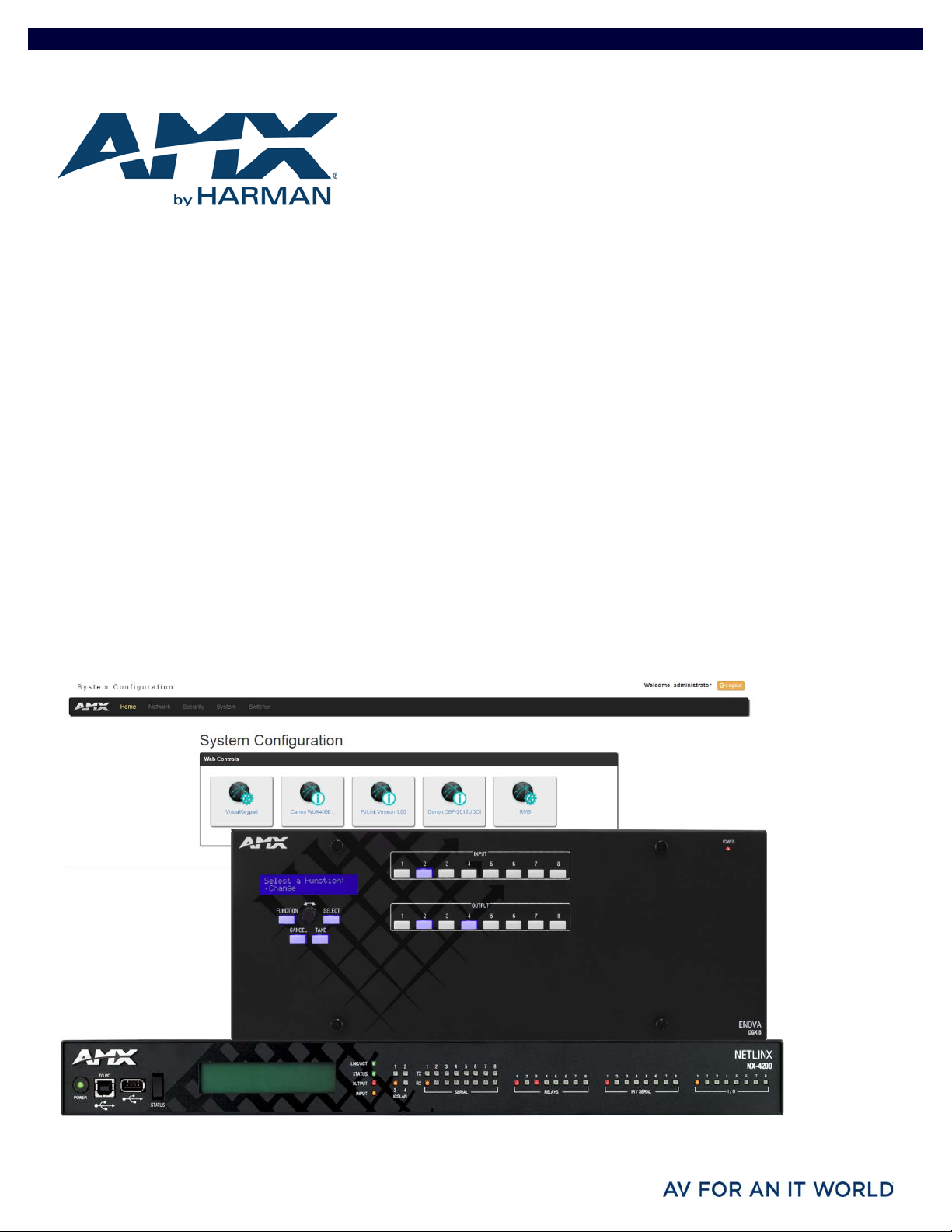
On-Board WebConsole User Interface ............................................................34
WebConsole UI Overview ............................................................................................... 34
System Configuration Interface Tips: ................................................................................................................ 34
Accessing the WebConsole .................................................................................................................. 35
Default User Names and Passwords..................................................................................................... 35
WebConsole - Network Options ......................................................................36
Network Overview............................................................................................................ 36
Network - IPv4 Setup ..................................................................................................... 37
IPv4 Options ......................................................................................................................................... 37
Network - IPv6 Setup ...................................................................................................... 38
Network - Date/Time ....................................................................................................... 38
Setting the Mode for the Clock Manager .............................................................................................. 39
Setting Daylight Savings Rules ............................................................................................................. 39
Selecting a Custom NIST Server .......................................................................................................... 39
Adding a Custom NIST Server to the List ............................................................................................. 40
Removing an NIST Server From the List ............................................................................................... 40
Clock Manager NetLinx Programming API ........................................................................................... 40
WebConsole - Security Options ......................................................................41
Security Overview........................................................................................................... 41
Login Rules............................................................................................................................................ 41
User and Role Name Rules.................................................................................................................................. 42
Password Rules................................................................................................................................................... 42
Security - General........................................................................................................... 43
System Level Security - System Security Settings ............................................................................... 43
System Security Options....................................................................................................................... 43
Security Presets.................................................................................................................................... 45
Audit Logs ............................................................................................................................................. 46
Banners................................................................................................................................................. 46
Security - Roles............................................................................................................... 47
Default Roles ......................................................................................................................................... 47
Role Permissions .................................................................................................................................. 48
Adding a New Role ................................................................................................................................ 49
Viewing and Modifying Role Security Settings Details ......................................................................... 50
Deleting a Role ...................................................................................................................................... 50
Page 5

Table o f C on t e n t s
5
NX-Series Controllers - WebConsole & Programming Guide
Locking/Disabling a Role ...................................................................................................................... 50
Security - Users .............................................................................................................. 51
Default User Accounts .......................................................................................................................... 51
Adding a New User................................................................................................................................ 52
Viewing and Editing User Security Settings ......................................................................................... 53
Deleting a User ..................................................................................................................................... 53
Locking/Disabling a User...................................................................................................................... 53
Security Settings - LDAP................................................................................................. 54
LDAP Options ........................................................................................................................................ 54
Accepting Changes............................................................................................................................... 55
Testing the Connection to the LDAP Server ......................................................................................... 55
Wired 802.1X support........................................................................................................................... 55
Security - Profile.............................................................................................................. 56
Changing a User’s Password ................................................................................................................ 56
WebConsole - System Options ........................................................................57
System Overview ............................................................................................................ 57
System - Info .................................................................................................................. 57
System - Devices ............................................................................................................. 58
Changing the System Number on the Master....................................................................................... 58
Changing the Device Number on a Device ............................................................................................ 58
Resetting the Master Controller to the Factory Defaults Configuration .............................................. 58
WebConsole - Modules Options ......................................................................59
Modules Overview ........................................................................................................... 59
Modules - Device Options ............................................................................................... 60
Configuring Device Binding Options ..................................................................................................... 60
Managing Device Driver Modules ......................................................................................................... 60
Uploading a Module............................................................................................................................................ 60
Archiving a Module ............................................................................................................................................. 60
Deleting a Module ............................................................................................................................................... 60
Modules - Bindings ......................................................................................................... 61
Configuring Application-Defined Devices............................................................................................. 62
Application Devices and Association Status......................................................................................... 63
Viewing Physical Device Properties...................................................................................................... 63
Modules - User-Defined Devices .................................................................................... 64
Adding a User-Defined Device .............................................................................................................. 64
Modules - Active Devices................................................................................................. 65
Searching For All Compatible Duet Modules for a Selected Device ..................................................... 65
Viewing Physical Device Properties...................................................................................................... 66
WebConsole - Switching Options ....................................................................67
Switching Overview ........................................................................................................ 67
Color-coded Switch Selection and Switching Orientation ................................................................................. 67
Switching Page Components................................................................................................................ 68
Page 6

Table o f C on t e n t s
6
NX-Series Controllers - WebConsole & Programming Guide
Switch Mode.......................................................................................................................................... 69
Configuring/Switching the Downmix Signal ........................................................................................ 70
Designating an Input for Downmixing (from Configuration page) ...................................................... 70
Configuration Page......................................................................................................... 71
Configuration Components .................................................................................................................. 71
Video Settings....................................................................................................................................... 73
Inputs Only ......................................................................................................................................................... 73
Outputs Only ....................................................................................................................................................... 73
DXLink Video Settings........................................................................................................................... 75
DXLink (Twisted Pair or Fiber) Transmitters (for selected video input) ............................................................ 75
DXLink (Twisted Pair or Fiber) Receivers (for selected video output)............................................................... 75
Audio Settings ...................................................................................................................................... 76
Inputs Only ......................................................................................................................................................... 76
Outputs Only ....................................................................................................................................................... 77
DXLink Audio Settings .......................................................................................................................... 78
DXLink (Twisted Pair or Fiber) Transmitter (for selected audio input) ............................................................. 78
DXLink (Twisted Pair or Fiber) Receivers (for selected audio output)............................................................... 79
EDID Configuration ............................................................................................................................... 79
Setting an EDID for an Input:................................................................................................................ 79
Setting an EDID for an Output:.............................................................................................................. 79
Setting the EDID Mode for an Audio Input: .......................................................................................... 79
Loading and Saving EDIDs .................................................................................................................... 79
Status Page..................................................................................................................... 80
System Configuration Interface Tips ................................................................................................................. 81
NetLinx Programming .....................................................................................82
Overview .......................................................................................................................... 82
Port Assignments by NetLinx Master .............................................................................. 82
Port Assignments by All-in-One-Presentation Switcher ................................................. 82
Port Assignments by Massio ControlPad ........................................................................ 82
Serial, IR, AxLink, and PoE Port Diagnostics ................................................................... 83
Master SEND_COMMANDs .............................................................................................. 84
CLOCK .................................................................................................................................................................................... 84
G4WC ..................................................................................................................................................................................... 84
~IGNOREEXTERNALCLOCKCOMMANDS................................................................................................................................. 84
Master IP Local Port SEND_COMMANDs.......................................................................... 85
UDPSENDTO ............................................................................................................................................................................ 85
SSH SEND_COMMANDs.................................................................................................... 86
SSH_CLIENT_CLOSE ............................................................................................................................................................... 86
SSH_CLIENT_OPEN ................................................................................................................................................................. 86
LED SEND_COMMANDs.................................................................................................... 87
LED-DIS.................................................................................................................................................................................. 87
LED-EN ................................................................................................................................................................................... 87
RS232/422/485 Ports Channels ................................................................................... 87
RS-232/422/485 SEND_COMMANDs .............................................................................. 88
B9MOFF................................................................................................................................................................................... 88
B9MON .................................................................................................................................................................................... 88
Page 7

Table o f C on t e n t s
7
NX-Series Controllers - WebConsole & Programming Guide
CHARD..................................................................................................................................................................................... 88
CHARDM.................................................................................................................................................................................. 88
CLEAR FAULT .......................................................................................................................................................................... 88
CTSPSH................................................................................................................................................................................... 88
CTSPSH OFF ............................................................................................................................................................................ 88
GET BAUD ............................................................................................................................................................................... 89
GET FAULT .............................................................................................................................................................................. 89
GET STATUS............................................................................................................................................................................ 89
HSOFF ..................................................................................................................................................................................... 89
HSON....................................................................................................................................................................................... 89
RXCLR ..................................................................................................................................................................................... 89
RXOFF ..................................................................................................................................................................................... 89
RXON....................................................................................................................................................................................... 89
SET BAUD............................................................................................................................................................................... 90
SET FAULT DETECT OFF ......................................................................................................................................................... 90
SET FAULT DETECT ON........................................................................................................................................................... 90
TSET BAUD............................................................................................................................................................................. 90
TXCLR .................................................................................................................................................................................... 91
XOFF....................................................................................................................................................................................... 91
XON ........................................................................................................................................................................................ 91
RS-232/422/485 SEND_STRING Escape Sequences...................................................... 92
27,17,<time> ......................................................................................................................................................................... 92
27,18,0 ................................................................................................................................................................................... 92
27,18,1 ................................................................................................................................................................................... 92
27,19,<time> ......................................................................................................................................................................... 92
27,20,0 ................................................................................................................................................................................... 92
27,20,1 ................................................................................................................................................................................... 92
ESCSEQOFF ............................................................................................................................................................................. 92
ESCSEQON .............................................................................................................................................................................. 92
IR/Serial Ports Channels................................................................................................. 93
IRRX Port Channels ......................................................................................................... 93
IR/Serial SEND_COMMANDs............................................................................................ 93
CAROFF ................................................................................................................................................................................... 93
CARON .................................................................................................................................................................................... 93
CH ........................................................................................................................................................................................... 93
CLEAR FAULT .......................................................................................................................................................................... 93
CP........................................................................................................................................................................................... 94
CTOF ...................................................................................................................................................................................... 94
CTON...................................................................................................................................................................................... 94
GET BAUD .............................................................................................................................................................................. 94
GET FAULT ............................................................................................................................................................................. 94
GET MODE .............................................................................................................................................................................. 94
GET STATUS........................................................................................................................................................................... 94
IROFF ...................................................................................................................................................................................... 95
POD ......................................................................................................................................................................................... 95
POF.......................................................................................................................................................................................... 95
PON ......................................................................................................................................................................................... 95
PTOF........................................................................................................................................................................................ 95
PTON ....................................................................................................................................................................................... 95
SET BAUD................................................................................................................................................................................ 96
SET FAULT DETECT OFF .......................................................................................................................................................... 96
SET FAULT DETECT ON............................................................................................................................................................ 96
SET IO LINK ............................................................................................................................................................................ 96
SET MODE............................................................................................................................................................................... 97
SP........................................................................................................................................................................................... 97
XCH ........................................................................................................................................................................................ 97
XCHM ...................................................................................................................................................................................... 98
Input/Output SEND_COMMANDs..................................................................................... 99
GET DBT .................................................................................................................................................................................. 99
SET DBT .................................................................................................................................................................................. 99
GET INPUT .............................................................................................................................................................................. 99
SET INPUT .............................................................................................................................................................................. 99
Page 8

Table o f C on t e n t s
8
NX-Series Controllers - WebConsole & Programming Guide
PoE SEND_COMMANDs ................................................................................................. 100
GET CLASS ........................................................................................................................................................................... 100
GET CURRENT ...................................................................................................................................................................... 100
GET FAULT ........................................................................................................................................................................... 100
GET STATUS......................................................................................................................................................................... 100
GET VOLTAGE....................................................................................................................................................................... 100
SET FAULT DETECT OFF ....................................................................................................................................................... 100
SET FAULT DETECT ON......................................................................................................................................................... 100
SET POWER OFF ................................................................................................................................................................... 100
SET POWER ON..................................................................................................................................................................... 100
AxLink SEND_COMMANDs............................................................................................. 101
AXPWROFF ........................................................................................................................................................................... 101
AXPWRON ............................................................................................................................................................................ 101
GET AX FAULT...................................................................................................................................................................... 101
Audit Log SEND_COMMANDs ........................................................................................ 101
LOG ...................................................................................................................................................................................... 101
Authentication.............................................................................................................. 102
Library Calls ........................................................................................................................................ 102
TLS_CLIENT_CLOSE ............................................................................................................................................................. 102
TLS_CLIENT_OPEN............................................................................................................................................................... 102
VALIDATE_NETLINX_ACCOUNT........................................................................................................................................... 103
VALIDATE_NETLINX_ACCOUNT_WITH_PERMISSION ......................................................................................................... 103
Terminal (Program Port/Telnet) Commands .............................................. 104
Overview ....................................................................................................................... 104
Establishing a Terminal Connection via the Program Port .......................................... 104
Establishing a Terminal Connection via Telnet ............................................................ 104
Terminal Commands .................................................................................................... 105
----- Help ----- <D:P:S> ........................................................................................................................................................ 105
? or Help............................................................................................................................................................................... 105
ADD AUDIT SERVER [D:P:P] ................................................................................................................................................. 105
AUTO LOCATE (ENABLE|DISABLE|STATUS) ........................................................................................................................ 105
BOOT STATUS ...................................................................................................................................................................... 105
CHANGE PASSWORD............................................................................................................................................................ 105
CLEAR AUDIT ....................................................................................................................................................................... 105
CLEAR HTTPS REDIRECT...................................................................................................................................................... 105
CLEAR MAX BUFFERS........................................................................................................................................................... 105
CLEAR PERSISTENT VARS.................................................................................................................................................... 105
CPU USAGE .......................................................................................................................................................................... 105
DATE .................................................................................................................................................................................... 105
DATE/TIME ON|OFF ............................................................................................................................................................. 105
DEVICE DEBUG..................................................................................................................................................................... 105
DEVICE HOLDOFF ON|OFF .................................................................................................................................................... 105
DEVICE STATUS <D:P:S>..................................................................................................................................................... 105
DIPSWITCH.......................................................................................................................................................................... 105
DISK FREE ............................................................................................................................................................................ 105
DNS LIST <D:P:S>................................................................................................................................................................ 106
DOT1X (ENABLE|DISABLE|STATUS).................................................................................................................................... 106
ECHO ON|OFF....................................................................................................................................................................... 106
EXPORT (CONFIG|CLONE) TO USB (FRONT|BACK) ............................................................................................................. 106
EXPORT AUDIT to USB (FRONT|BACK)................................................................................................................................ 106
FIPS MODE ........................................................................................................................................................................... 106
GET AUDIT STATUS ............................................................................................................................................................. 106
GET DEVICE HOLDOFF.......................................................................................................................................................... 107
GET DEVICE TRAFFIC........................................................................................................................................................... 107
GET DUET MEMORY.............................................................................................................................................................. 107
GET ICSLAN ......................................................................................................................................................................... 107
GET IP <D:P:S>.................................................................................................................................................................... 107
GET LEASES ......................................................................................................................................................................... 107
GET OCSP URL...................................................................................................................................................................... 107
Page 9

Table o f C on t e n t s
9
NX-Series Controllers - WebConsole & Programming Guide
GET PLATFORM INFO ........................................................................................................................................................... 107
HELP SECURITY ................................................................................................................................................................... 107
ICSPMON ENABLED|DISABLED [PORT]................................................................................................................................ 107
IMPORT CONFIG .................................................................................................................................................................. 107
IMPORT IRL.......................................................................................................................................................................... 107
IMPORT KIT ......................................................................................................................................................................... 107
IMPORT TKN ........................................................................................................................................................................ 108
IP STATUS ........................................................................................................................................................................... 108
IPDD..................................................................................................................................................................................... 108
JAVA SECURITY ................................................................................................................................................................... 108
LIST AUDIT FILES ................................................................................................................................................................ 108
LIST AUDIT SERVERS........................................................................................................................................................... 108
LOG FORMAT ........................................................................................................................................................................ 108
MAIL RESET ......................................................................................................................................................................... 108
MAIL STATUS....................................................................................................................................................................... 108
MANAGE FIRMWARE............................................................................................................................................................ 108
MEM ..................................................................................................................................................................................... 108
MSG ON|OFF......................................................................................................................................................................... 109
MSG STATS .......................................................................................................................................................................... 109
NDP ...................................................................................................................................................................................... 109
NETLINX LOG LEVEL............................................................................................................................................................. 109
OFF [D:P:S or NAME,CHAN].................................................................................................................................................. 109
ON [D:P:S or NAME,CHAN] ................................................................................................................................................... 109
PASS [D:P:S or NAME].......................................................................................................................................................... 110
PHYSICAL STATUS............................................................................................................................................................... 110
PING [ADDRESS].................................................................................................................................................................. 110
PROGRAM (ENABLE|DISABLE|STATUS) .............................................................................................................................. 110
PROGRAM INFO.................................................................................................................................................................... 110
PULSE [D:P:S or NAME,CHAN].............................................................................................................................................. 110
PWD ..................................................................................................................................................................................... 110
REBOOT................................................................................................................................................................................ 110
REMOVE AUDIT SERVER [D:P:P]........................................................................................................................................... 111
RENEW DHCP ....................................................................................................................................................................... 111
REPORT FIRMWARE ............................................................................................................................................................. 111
REPORT NETLINX................................................................................................................................................................. 111
RESETADMINPASSWORD..................................................................................................................................................... 111
RESET FACTORY................................................................................................................................................................... 111
ROUTE MODE DIRECT|NORMAL ........................................................................................................................................... 111
SELINUX STATUS................................................................................................................................................................. 111
SEND_COMMAND D:P:S or NAME,COMMAND ....................................................................................................................... 111
SEND_LEVEL <D:P:S>,<LEVEL ID>,<LEVEL VALUE>............................................................................................................ 111
SEND_STRING D:P:S or NAME,STRING ................................................................................................................................ 111
SET DATE ............................................................................................................................................................................. 111
SET DEVICE REBOOT ............................................................................................................................................................ 111
SET DNS <D:P:S> ................................................................................................................................................................. 112
SET DUET MEMORY .............................................................................................................................................................. 112
SET FTP PORT ...................................................................................................................................................................... 112
SET HTTP PORT.................................................................................................................................................................... 112
SET HTTPS PORT.................................................................................................................................................................. 112
SET HTTPS REDIRECT .............................................................................................................
SET ICSLAN.......................................................................................................................................................................... 113
SET ICSP PORT .................................................................................................................................................................... 113
SET ICSP TCP TIMEOUT....................................................................................................................................................... 113
SET IP <D:P:S> .................................................................................................................................................................... 113
SET LOCKOUT....................................................................................................................................................................... 113
SET LOG COUNT ................................................................................................................................................................... 114
SET NOTIFY THROTTLE ........................................................................................................................................................ 114
SET OCSP URL...................................................................................................................................................................... 114
SET QUEUE SIZE .................................................................................................................................................................. 114
SET SELF SIGNED CERTIFICATE .......................................................................................................................................... 114
SET SSH PORT...................................................................................................................................................................... 114
SET SYSTEM NUMBER.......................................................................................................................................................... 115
SET TELNET PORT ................................................................................................................................................................ 115
SET THRESHOLD .................................................................................................................................................................. 115
SET TIME.............................................................................................................................................................................. 115
SET TIMELINE LOOPCNT...................................................................................................................................................... 115
SET UDP BC RATE ................................................................................................................................................................ 115
SET URL <D:P:S> ................................................................................................................................................................. 116
............................................. 112
Page 10

Table o f C on t e n t s
10
NX-Series Controllers - WebConsole & Programming Guide
SHOW AUDIT [FILENAME] ................................................................................................................................................... 116
SHOW AUDIT LOG ................................................................................................................................................................ 116
SHOW BUFFERS ................................................................................................................................................................... 116
SHOW COMBINE................................................................................................................................................................... 116
SHOW DEVICE <D:P:S>........................................................................................................................................................ 117
SHOW HTTPS REDIRECT ...................................................................................................................................................... 117
SHOW LOG............................................................................................................................................................................ 117
SHOW MAX BUFFERS ........................................................................................................................................................... 118
SHOW MEM .......................................................................................................................................................................... 118
SHOW NOTIFY ...................................................................................................................................................................... 118
SHOW REMOTE..................................................................................................................................................................... 118
SHOW ROUTE ....................................................................................................................................................................... 118
SHOW START LOG <START>................................................................................................................................................ 118
SHOW SYSTEM <S> ............................................................................................................................................................. 119
SHOW TCP............................................................................................................................................................................ 119
SHOW WATCHDOG ............................................................................................................................................................... 119
START LOG (ON|OFF)........................................................................................................................................................... 119
TIME..................................................................................................................................................................................... 119
TOD ADJUSTMENTS ............................................................................................................................................................. 119
URL LIST <D:P:S> ................................................................................................................................................................ 119
USB LOG [front|back] [enable|disable]............................................................................................................................... 119
ZEROCONF
[ENABLE|DISABLE|STATUS]............................................................................................................................................. 119
ESC Pass Codes .................................................................................................................................. 120
+ + ESC ESC......................................................................................................................................................................... 120
+ + ESC A ............................................................................................................................................................................. 120
+ + ESC D ............................................................................................................................................................................. 120
+ + ESC H............................................................................................................................................................................. 120
Using the ICSLAN Network ................................................................................................................. 120
DHCP Server...................................................................................................................................................... 120
Opening LAN and ICSLAN Sockets from Code.................................................................................................. 120
Accessing the Security Configuration Options ............................................................ 121
Setup Security Menu .................................................................................................... 122
Enabling LDAP via the Program Port .................................................................................................. 123
Security Options Menu........................................................................................................................ 124
Edit User Menu.................................................................................................................................... 125
Edit Device Menu................................................................................................................................. 125
Edit Role Menu .................................................................................................................................... 126
Access Rights Menu............................................................................................................................ 126
Adding a Role.................................................................................................................................................... 127
Default Security Configuration ........................................................................................................... 127
Telnet Diagnostics Commands..................................................................................... 128
PHYSICAL STATUS............................................................................................................................................................... 128
MSG STATS .......................................................................................................................................................................... 128
Logging Out of a Terminal Session............................................................................... 128
Notes on Specific Telnet/Terminal Clients .................................................................. 128
Windows Client Programs .................................................................................................................. 128
Linux Telnet Client .............................................................................................................................. 128
Appendix A: LDAP Implementation Details ...................................................129
Overview ....................................................................................................................... 129
Changes to LDAP Implementation (v1.4.x) ................................................................. 129
Active Directory/OpenLDAP Setup ..................................................................................................... 129
Page 11

Table o f C on t e n t s
11
NX-Series Controllers - WebConsole & Programming Guide
Changes to LDAP Implementation (v1.5.x).................................................................. 130
User Query Attribute........................................................................................................................... 130
FTP Access with LDAP Authentication................................................................................................ 130
SSH Access with LDAP Authentication ............................................................................................... 130
Assumptions and Prerequisites ................................................................................... 131
Example - Setting Up User's Access Rights ................................................................. 132
Administrator Access Example ........................................................................................................... 132
User Access Example.......................................................................................................................... 132
Appendix B: Certificates ................................................................................133
Overview ....................................................................................................................... 133
Certificate Information................................................................................................. 134
Creating an HTTPS KeyStore........................................................................................ 135
Step 1: Create the private key ............................................................................................................ 135
Step 2: Generate a CSR request ......................................................................................................... 135
Step 3: Send the master.csr file to the CA to have it signed. ............................................................. 135
Step 4: Import the newly signed certificate into the KeyStore .......................................................... 135
Step 5: Upload amxcert to the NX as HTTPS KeyStore and reboot the NX ........................................ 135
Creating & Installing Self-Signed HTTPS KeyStore ..................................................... 136
Generating a Self-Signed KeyStore .................................................................................................... 136
Installing a Self-Signed KeyStore....................................................................................................... 136
Creating/Updating the Duet TrustStore ...................................................................... 138
Acquiring/Installing Public Certificates ...................................................................... 139
Appendix C: SMTP Support .......................................................................... 140
Overview ....................................................................................................................... 140
SMTP Server Configuration .......................................................................................... 140
Sending Mail ................................................................................................................. 141
Appendix D: Clock Manager NetLinx Programming API .............................. 142
Types/Constants .......................................................................................................... 142
Library Calls.................................................................................................................. 142
CLKMGR_IS_NETWORK_SOURCED().................................................................................................................................... 142
CLKMGR_SET_CLK_SOURCE(CONSTANT INTEGER MODE).................................................................................................. 142
CLKMGR_IS_DAYLIGHTSAVINGS_ON() ............................................................................................................................... 142
CLKMGR_SET_DAYLIGHTSAVINGS_MODE(CONSTANT INTEGER ONOFF)........................................................................... 142
CLKMGR_GET_TIMEZONE() ................................................................................................................................................. 142
CLKMGR_SET_TIMEZONE(CONSTANT CHAR TIMEZONE[])................................................................................................. 142
CLKMGR_GET_RESYNC_PERIOD() ....................................................................................................................................... 142
CLKMGR_SET_RESYNC_PERIOD(CONSTANT INTEGER PERIOD) ......................................................................................... 142
CLKMGR_GET_DAYLIGHTSAVINGS_OFFSET(CLKMGR_TIMEOFFSET_STRUCT T)............................................................... 142
CLKMGR_SET_DAYLIGHTSAVINGS_OFFSET(CONSTANT CLKMGR_TIMEOFFSET_STRUCT T) ............................................ 142
CLKMGR_GET_ACTIVE_TIMESERVER(CLKMGR_TIMESERVER_STRUCT T) ......................................................................... 142
CLKMGR_SET_ACTIVE_TIMESERVER(CONSTANT CHAR IP[])............................................................................................. 142
CLKMGR_GET_TIMESERVERS(CLKMGR_TIMESERVER_STRUCT T[]) .................................................................................. 143
CLKMGR_ADD_USERDEFINED_TIMESERVER(CONSTANT CHAR IP[], CONSTANT CHAR URL[],
CONSTANT CHAR LOCATION[])........................................................................................................................................ 143
CLKMGR_DELETE_USERDEFINED_TIMESERVER(CONSTANT CHAR IP[]) ............................................................................ 143
CLKMGR_GET_START_DAYLIGHTSAVINGS_RULE() ............................................................................................................ 143
CLKMGR_SET_START_DAYLIGHTSAVINGS_RULE(CONSTANT CHAR RECORD[])................................................................ 143
Page 12

Table o f C on t e n t s
12
NX-Series Controllers - WebConsole & Programming Guide
CLKMGR_GET_END_DAYLIGHTSAVINGS_RULE() ................................................................................................................ 144
CLKMGR_SET_END_DAYLIGHTSAVINGS_RULE(CONSTANT CHAR RECORD[]).................................................................... 144
Page 13

13
NX-Series Controllers - WebConsole & Programming Guide
Overview
NetLinx NX Integrated Controllers
NetLinx NX Integrated Controllers (Masters) can be programmed to control RS-232/422/485, Relay, IR/Serial, and Input/Output
devices using the NetLinx Studio application (version 4.0 or higher).
NetLinx NX Integrated Controllers
Name Description
NX-1200 NetLinx NX Integrated Controller
NX-2200 NetLinx NX Integrated Controller
NX-3200 NetLinx NX Integrated Controller
NX-4200 NetLinx NX Integrated Controller
NOTE: Refer to the Products > Central Controllers > NetLinx NX Integrated Controllers page at www.amx.com for details and
variations available for these products.
NX controllers feature an on-board Web Console which allows you to connect to the NX controller via a web browser and make
various configuration and security settings. The WebConsole is described in this document (starting with the On-Board WebConsole
User Interface section on page 34).
NX controllers are Duet-compatible and can be upgraded via firmware. Duet is a dual-interpreter firmware platform from AMX which
combines the proven reliability and power of NetLinx with the extensive capabilities of the Java
Edition Embedded) platform. Duet simplif ies the programming of a system that includes the NX controller and other third party
devices by standardizing device and function definitions, defaulting touch panel button assignments, and controlling feedback
methods.
Dynamic Device Discovery makes integration even easier by automatically identifying and communicating with devices which
support this beaconing technology.
®
MicroEdition (Java Standard
Overview
Enova DVX All-in-One Presentation Switchers
Enova Digital Media Switchers
Name Description
DVX-3250HD 10x4 All-In-One Presentation Switchers with NX Control (Multi-Format, HDMI Inputs)
DVX-3255HD 10x4 All-In-One Presentation Switchers with NX Control (Multi-Format, HDMI, 2 DXLink Inputs)
DVX-3256HD 10x4 All-In-One Presentation Switchers with NX Control (Multi-Format, HDMI, 4 DXLink Inputs)
DVX-2250HD 6x3 All-In-One Presentation Switchers with NX Control (Multi-Format, HDMI Inputs)
DVX-2255HD 6x3 All-In-One Presentation Switchers with NX Control (Multi-Format, HDMI, DXLink Inputs)
DVX-2210HD 4x2 All-In-One Presentation Switchers with NX Control (Multi-Format, HDMI Inputs)
NOTE: Refer to the Products > All-in-One Presentation Switchers page at www.amx.com for details and variations available for these
products.
Enova DVX-22xxHD & DVX-325xHD
Enova DVX-22xxHD All-in-One Presentation Switchers utilize an NX-2200 Controller, therefore all controller-related information
that applies to the NX-2200 is fully applicable to DVX-22xxHD products.
Enova DVX-325xHD All-in-One Presentation Switchers utilize an NX-3200 Controller, therefore all controller-related information
that applies to the NX-3200 is fully applicable to DVX-325xHD products.
Enova DVX All-In-One Presentation Switchers features many functions that do not apply to NX-series Controllers, most of
which relate directly to the Audio/Video capabilities of the DVX.
Refer to the Enova DVX-325xHD/22xxHD All-in-One Presentation Switchers Instruction Manual for information specific to
Enova DVX products.
Page 14

Overview
14
NX-Series Controllers - WebConsole & Programming Guide
Enova DGX Digital Media Switchers
Enova Digital Media Switchers
Name Description
DGX8-ENC Enova DGX 8 Enclosure
DGX16-ENC Enova DGX 16 Enclosure
DGX32-ENC-A Enova DGX 32 Enclosure
DGX64-ENC Enova DGX 64 Enclosure
NOTE: Refer to the Products > Digital Media Switchers page at www.amx.com for details and variations available for these products.
Massio™ ControlPads
Massio ControlPads
Name Description
MCP-106 6-Button Massio ControlPad
MCP-108 8-Button Massio ControlPad
NOTE: Refer to the Products > ControlPads page at www.amx.com for details and variations available for these products.
About This Document
This document describes using the on-board WebConsole, as well as NetLinx send commands and terminal communications to
configure the NX controllers:
Each major section of the WebConsole is described in a separate section of this document. Refer to:
the On-Board WebConsole User Interface section on page 34,
the WebConsole - Network Options section on page 46,
the WebConsole - Security Options section on page 41,
the WebConsole - System Options section on page 57, and
the WebConsole - Switching Options section on page 67.)
The Initial Conf iguration and Firmware Upgrade section on page 5 describes upgrading the firmware on NX controllers.
The NetLinx Programming section on page 82 lists and defines the NetLinx send commands that are supported by the NX
controllers.
The Terminal (Program Port/Telnet) Commands section on page 104 describes the commands and options available via a
Telnet terminal session with the NX controller.
Differences in DEFINE_PROGRAM Program Execution
Due to differences in the underlying architecture of the X-Series masters, changing variables in the DEFINE_PROGRAM section of
code can negatively impact program performance. It has always been considered poor programming practice to change a variable
within the DEFINE_PROGRAM section of code. If you have legacy NetLinx code that does change a variable in this section it’s very
likely that timing differences will cause your code to run slower and appear less respo nsive on an NX-Series controller and can have
other adverse effects on platform reliability in the area of connectivity and data throughput.
The DEFINE_PROGRAM section of NetLinx code contains the code known as mainline. Mainline is the section of the program that is
executed on a periodic basis by the NetLinx Master Controller. Under normal operation, the DEFINE_PROGRAM section executes at
least once every half second. Various system activities can cause the DEFINE_PROGRAM section to execute more frequently than
every half second. For example, any time an external event occurs (button push, level change), the DEFINE_PROGRAM section must
re-execute to ensure that any change caused by the event processes through the DEFINE_PROGRAM section code block. This is
also the case for changes to global variables. Any variable change requires the DEFINE_PROGRAM section to re-execute to process
the new variable value through the DEFINE_PROGRAM code block.
Because high CPU usage can be detrimental to the system functionality on an NX master, AMX recommends the complete
deprecation of the DEFINE_PROGRAM section. Syntactically, it is still valid to use the DEFINE_PROGRAM section in your NetLinx
application, but it is no longer recommended. All logic that you would normally place in the DEFINE_PROGRAM section is handled
better in the DEFINE_EVENT section.
Feedback statements remain the most common usage in the DEFINE_PROGRAM section. Because of periodically executing
DEFINE_PROGRAM, you can rely on the program to update user feedback at a regular interval. However, if the DEFINE_PROGRAM
section executes too frequently with the needless iterations expending the CPU to repetitively evaluate the feedback statements.
TIMELINE_EVENTS provide a much more efficient mechanism for evaluating feedback statements. A single timeline triggering every
500ms provides the same periodic execution as the DEFINE_PROGRAM section without the unwanted recursive execution behavior.
Consider the following DEFINE_PROGRAM section containing feedback statements in PRGM EX. 1:
DEFINE_PROGRAM
[dvTP,1] = [dvDev,1]
[dvTP,2] = value1
[dvTP,3] = ![dvTP,3]
PRGM EX. 1 DEFINE_PROGRAM with feedback statements
Page 15

Overview
15
NX-Series Controllers - WebConsole & Programming Guide
The code in PRGM EX. 1 would be better implemented using a timeline, as illustrated in PRGM EX. 2:
DEFINE_CONSTANTS
LONG FEEDBACK_TIMES[1] = {500}
INTEGER FEEDBACK_TIMELINE = 1
DEFINE_START
TIMELINE_CREATE(FEEDBACK_TIMELINE, FEEDBACK_TIMES, 1, TIMELINE_RELATIVE, TIMELINE_REPEAT)
DEFINE_EVENT
TIMELINE_EVENT[FEEDBACK_TIMELINE]
{
[dvTP,1] = [dvDev,1]
[dvTP,2] = value1
[dvTP,3] = ![dvTP,3]
}
PRGM EX. 2 Using feedback statements in a timeline
The code in PRGM EX. 2 evaluates the feedback statements every half second regardless of other program activity. If a shorter
feedback refresh is needed, you can specify a smaller constant in the FEEDBACK_TIMES constant. Even a time of 100ms executes
far less frequently than a DEFINE_PROGRAM section stuck in an infinite execution loop due to a global variable change.
By moving all code out of the DEFINE_PROGRAM section, you ensure your NetLinx application is executing only when needed, and
therefore not expending unnecessary CPU cycles.
If you choose to continue to use the DEFINE_PROGRAM section, it is critical that you ensure that you are not modifying a variable
within the section. Any variable change will force a repeated execution of the section, thereby creating an infinite execution loop.
Variables should never fal l o n the left-hand side of an evaluation statement, as in PRGM EX. 3.
DEFINE_PROGRAM
Var1 = !Var1
PRGM EX. 3 Variable declared within the DEFINE_PROGRAM section
You must also take care to not inadvertently change a variable. For example, if a function is called within DEFINE_PROGRAM, then
that function must likewise not change a global variable. Additionally, accessing global “values” such as TIME and DATE constitute
a variable change. Take for example the code in PRGM EX. 4:
IF (TIME = ’22:00:00’)
{…}
PRGM EX. 4 Time check
At first glance, this code does not appear to change a variable. It is simply checking to see if the current time is equal to 22:00:00.
However, this code effectively changes the TIME variable by retrieving the current system time and assigning it to the TIME variable.
If this code were present in a DEFINE_PROGRAM section, it would infinitely re-execute the DEFINE_PROGRAM section. You should
place evaluations such as this in a TIMELINE_EVENT similar to the feedback timeline described earlier.
CPU Usage
The new NX masters provide several diagnostics that can be used to determine if your program is overloading the CPU and, if so,
what might be causing its excessive use. All of these commands are accessible through a Telnet or USB terminal connection with
the master.
>cpu usage
Gathering CPU usage over a 10 second period. Please wait ...
CPU usage = 2.10% over a 10 second period.
An idle application normally runs below 5% of the CPU. If your idle application shows more usage than this, then it is probable that
your application is experiencing excessive execution of the DEFINE_PROGRAM section.
You can use the following diagnostic to diagnose executions of the DEFINE_PROGRAM section:
>superuser 10
>enable interp stats
>show interp stats
-- Mainline Executions due to:
Variable Change : 0
Pending Int Event : 0
Pulse Expiration : 0
Hold Expiration : 0
DoPush Expiration : 0
Wait Expiration : 0
Until Expiration : 0
Timeline Expiration : 0
Periodic Mainline : 0
Current internal event count = 0
Page 16

Overview
16
NX-Series Controllers - WebConsole & Programming Guide
These statistics indicate how many times mainline has been executed and why it has been executed. Repeatedly executing “show
interp stats” will give you an idea which code construct is causing mainline to execute. For example, if a variable is being changed,
you will see the “Variable Change” count increasing. If a timeline is firing quickly, you will see the TIMELINE_EXPIRATION count
increasing. A normal idle application that is executing DEFINE_PROGRAM every half second will only see the “Periodic Mainline”
count increasing.
For example, consider this diagnostic output from a NetLinx application that is changing a variable in DEFINE_PROGRAM:
>show interp stats
-- Mainline Executions due to:
Variable Change : 50927
Pending Int Event : 1
Pulse Expiration : 0
Hold Expiration : 0
DoPush Expiration : 0
Wait Expiration : 0
Until Expiration : 0
Timeline Expiration : 0
Periodic Mainline : 0
Current internal event count = 1
>show interp stats
-- Mainline Executions due to:
Variable Change : 62295
Pending Int Event : 1
Pulse Expiration : 0
Hold Expiration : 0
DoPush Expiration : 0
Wait Expiration : 0
Until Expiration : 0
Timeline Expiration : 0
Periodic Mainline : 0
Current internal event count = 0
>show interp stats
-- Mainline Executions due to:
Variable Change : 72386
Pending Int Event : 1
Pulse Expiration : 0
Hold Expiration : 0
DoPush Expiration : 0
Wait Expiration : 0
Until Expiration : 0
Timeline Expiration : 0
Periodic Mainline : 0
Current internal event count = 1
Notice the “Variable Change” count is increasing rapidly.
These diagnostics will not tell you where in your application the offending code resides. Finding the offending code requires a
process of code analysis and possibly selectively commenting out sections of code to isolate the offender.
NOTE: NetLinx modules each have a DEFINE_PROGRAM section that must abide by the same rules as the main program, so the
offending code could be in a module.
Page 17

17
NX-Series Controllers - WebConsole & Programming Guide
Quick Setup and Conf iguration Overview
Installation Procedures
The general steps involved with most common installations of this device include:
Unpack and confirm the contents of box (see the Specifications tables in the Hardware Reference Guide for each controller).
Connect all rear panel components and supply power to the NX controller from the external power supply.
Conf iguration and Communication
The general steps involved with setting up and communicating with the NX controller’s on-board Master. In the initial
communication process:
Set the boot-time operations on the rear Configuration DIP switch. (The DIP switch is located on the front panel of the
NX-1200.)
Connect and communicate with the on-board Master via the Program port.
Set the System Value being used with the on-board Master.
Re-assign any Device values.
Retrieve the DHCP Address for the on-board Master or assign a Static IP to the on-board Master.
Once the IP information is determined, re-work the parameters for Master Communication to connect to the on-board
Master via the LAN and not the Program port.
Update the On-board Master and Controller Firmware
Before using your new NX controller, you must first update your NetLinx Studio to the most recent release.
Upgrade the Integrated Contro ller f irmware through an IP address via the LAN connector (Upgrading Firmware section on
page 28) (IP recommended).
Upgrade the on-board Master firmware through an IP address via the LAN connector (Upgrading Firmware section on
page 28) (IP recommended).
Conf igure NetLinx Security on the NX Controller
Setup and finalize your NetLinx Security Protocols (WebConsole - Security Options section on page 41).
Program your NX controller (NetLinx Programming section on page 82).
Overview
Using Zero Configuration
NetLinx Masters support using "zero-configuration" client software to quickly install multiple devices on the network.
Bonjour (Zero-Conf iguration) Client
You can use a zero-configuration client to determine the IP address of the Controllers. There are many zero-configuration clients
available which are free and widely available for download. NetLinx Studio includes a zero-configuration client which we will use for
the purposes of this document.
If you don’t already have it installed on your PC, download and install NetLinx Studio 4.0 before you begin.
Connecting to a Network with a DHCP Server
By using the Controller’s Zeroconf feature and the NetLinx Studio, you can install and configure multiple devices on the network
without pre-conf iguring each device befo re installation.
The dealer only needs to match the serial number printed on the backside of the device or from the label on the box to the serial
number that is displayed in the Bonjour browser pane.
1. Launch NetLinx Studio 4.0.
2. Once power is applied to the device, select the Zero-Config tab on the Workspace bar (see FIG. 1).
Zero-Config tab
FIG. 1
Page 18
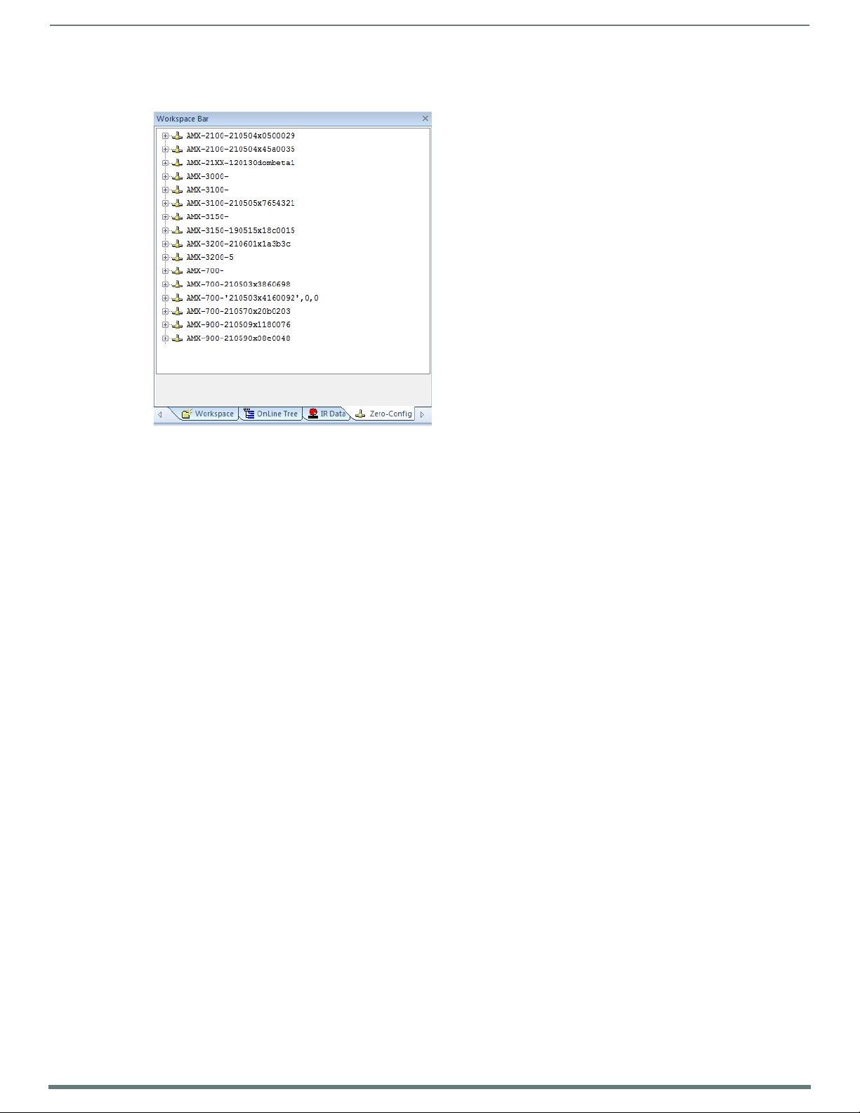
Overview
18
NX-Series Controllers - WebConsole & Programming Guide
3. In the Workspace area, right-click and select Refresh Zero Conf ig List. The controller appears in the list of devices as shown in
FIG. 2:
FIG. 2
Workspace bar (Zero-Config tab selected)
4. Double-click the Master you want to access it in the WebConsole.
Accessing the Master requires valid login information. The browser will prompt you for User ID and Password before displaying
the configuration pages for the selected device.
Note that the serial number is appended to the name of the device.
After logging in, you can configure the device (changing IP settings, NetLinx settings, User settings, etc) via the pages in the
WebConsole (see the On-Board WebConsole User Interface section on page 34).
Page 19
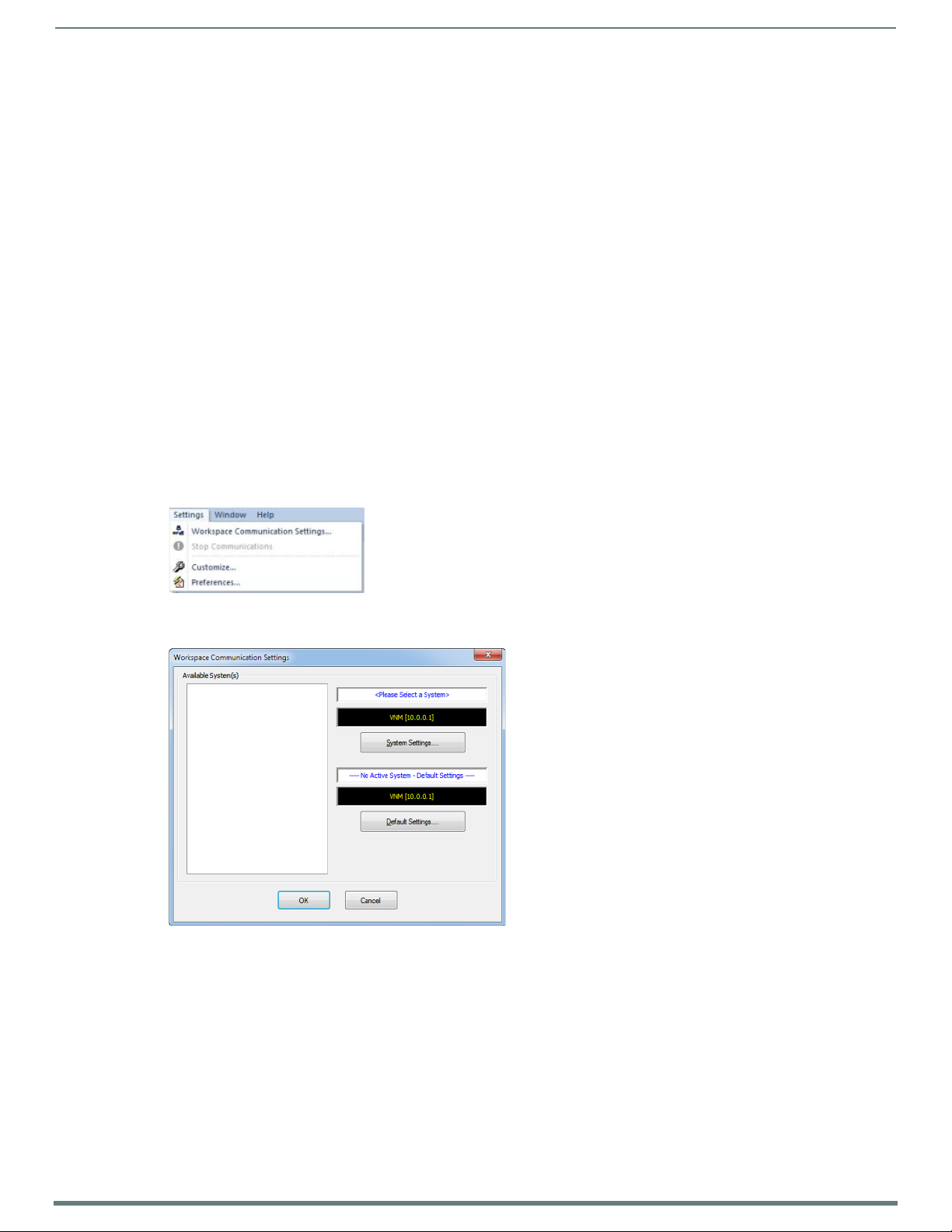
19
NX-Series Controllers - WebConsole & Programming Guide
Initial Conf iguration
Overview
This section describes using the NetLinx Studio software application to perform the initial configuration of the NetLinx Master.
NetLinx Studio is used to setup a System number, obtain/assign the IP/URL for the NX controller, as described in this section (as
well as to transfer firmware Kit files to the Master - see the Upgrading Firmware section on page 28).
Before You Start
1. Verify you have the latest version of the NetLinx Studio application version 4.0 installed on your PC.
NetLinx Studio is available to download from www.amx.com. Login to download the latest version. Alternatively, if it is already
installed, use the Web Update option in NetLinx Studio’s Help menu to obtain the latest version.
The default location for the NetLinx Studio application is Start > Programs > AMX Control Disc > NetLinx Studio > NetLinx
Studi o.
2. Verify that a LAN cable is connected from the Master to the LAN Hub.
3. Connect a programming cable (Type-B USB) from the Program Port on the Master to a USB port on the PC being used for
programming.
4. Apply power to the Master.
Preparing the Master for USB Communication
To establish USB communication with the Master via the PROGRAM port with Type-B-to-Type-A cable:
1. Launch NetLinx Studio and select Settings > Workspace Communication Settings (FIG. 3):
Initial Configuration
NetLinx Studio menu bar - Settings > Workspace Communication Settings
FIG. 3
2. This opens the Workspace Communication Settings dialog (FIG. 4).
FIG. 4 Workspace Communication Settings dialog
Page 20
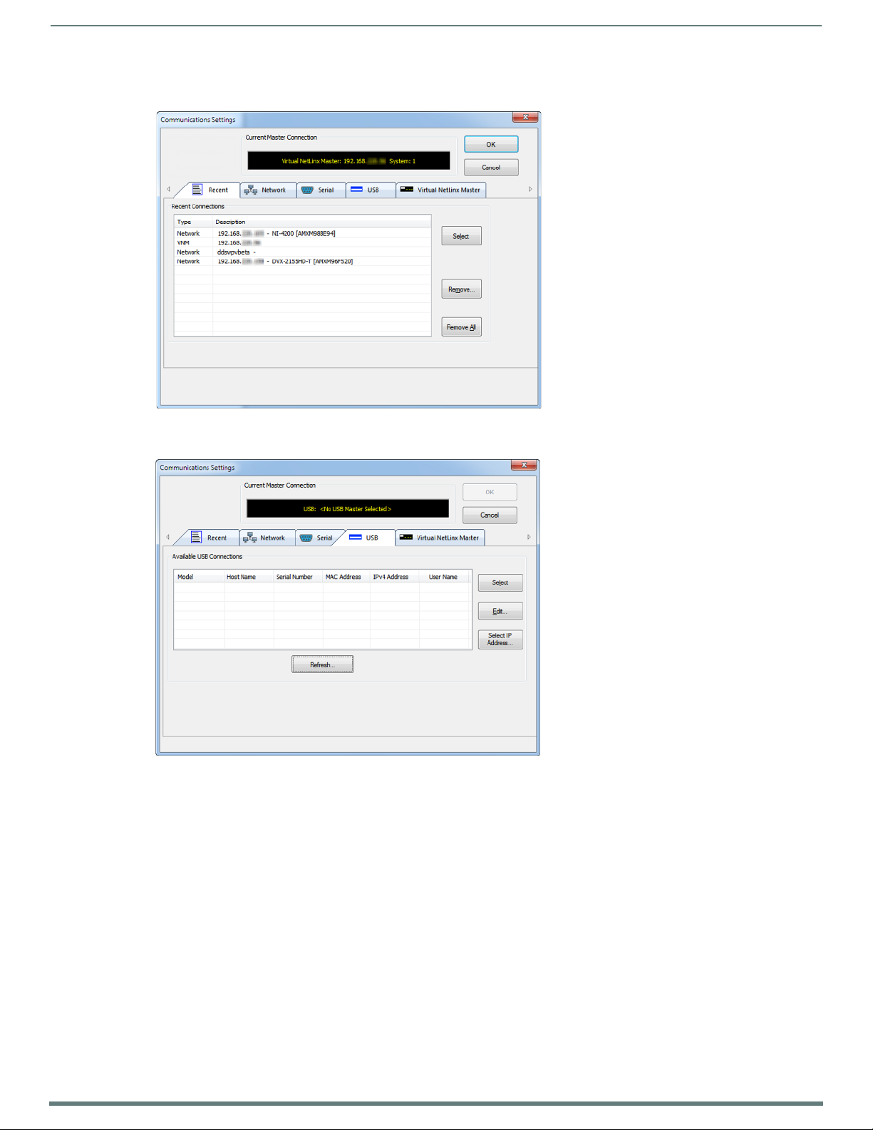
Initial Configuration
20
NX-Series Controllers - WebConsole & Programming Guide
3. Click the System Settings button to open the Communications Settings dialog (FIG. 5). If there is no system selected, click the
Default Settings button to open the dialog.
FIG. 5
Communication Settings dialog - Recent tab
4. Select the USB tab to view the USB options (FIG. 6).
FIG. 6 Communications Settings dialog - USB tab
5. On the USB tab, highlight the Master you want to connect to and click Select.
6. Click Edit to open the Edit USB Master’s Username/Password dialog to set the user name and password for authentication
access to the Master. This step is optional. You can only change the user name and password in the dialog. The additional
fields are view-only.
7. Click OK to close the USB Master’s Username/Password dialog, and click OK in the Communication Settings dialog to return to
the Communication Settings dialog, now indicating the USB-connected Master as the current connection conf iguration.
8. Click OK to close the Communication Settings dialog and return to the main application.
Page 21
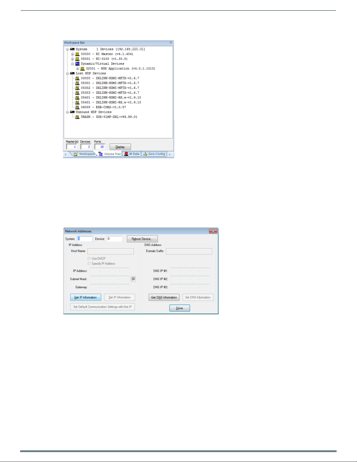
Initial Configuration
21
NX-Series Controllers - WebConsole & Programming Guide
9. Right-click the Online Tree tab entry and select Refresh System: the Controller should appear in the Device Tree (FIG. 7):
FIG. 7
Workspace Bar - Online Tree
NOTE: If the Master does not appear in the list, verify that the USB cable is connected properly.
Once USB communication has been established, use NetLinx Studio to configure the Controller for LAN Communication, as
described in the next section.
Conf iguring the NX Controller for LAN Communication
1. Use a LAN cable to connect the Controller to the LAN to which the PC running NetLinx Studio is connected.
2. Select Diagnostics > Network Addresses from the menu bar to open the Network Addresses dialog (FIG. 8). Use the options in
this dialog to select to either use DHCP or specify an IP address.
FIG. 8 Network Addresses dialog
Page 22
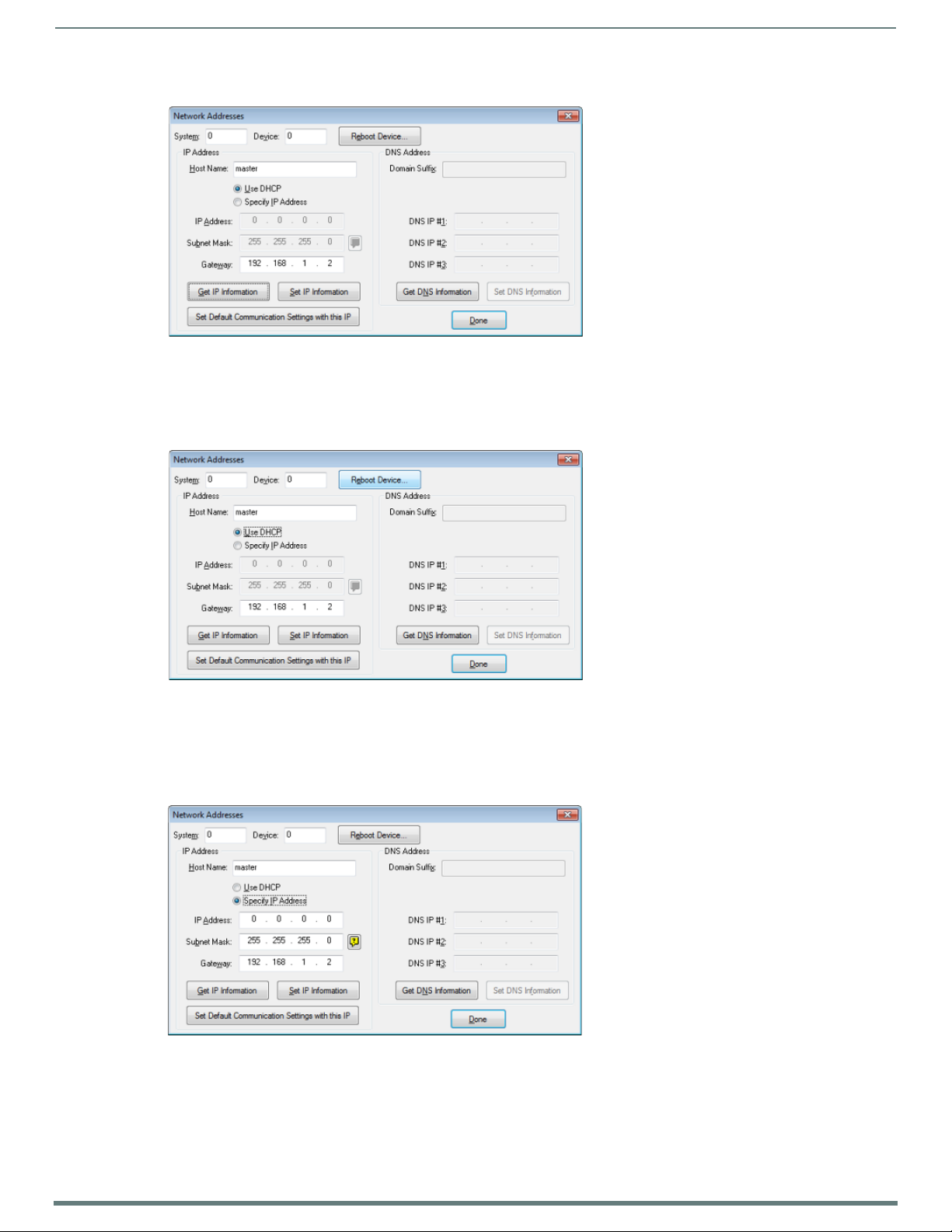
Initial Configuration
22
NX-Series Controllers - WebConsole & Programming Guide
3. Click Ge t I P I nf o r ma ti o n to enable the fields for editing (FIG. 9):
FIG. 9
Network Addresses dialog showing initial IP information
4. Enter the System, Device (0 for NetLinx Masters), and Host Name information.
NOTE: Host names may contain only the ASCII letters 'a' through 'z' (in a case-insensitive manner), the digits '0' through '9', and the
hyphen ('-').
5. To configure a network address via DHCP (FIG. 10):
FIG. 10 Network Addresses dialog (DHCP)
a. Select Use DHCP.
b. Click Set IP Information to retain the DHCP setting.
c. To finish the process, click Reboot Device.
d. Click Done to close the dialog.
6. To specify a network IP address (FIG. 11):
FIG. 11 Network Addresses dialog (Specify IP Address)
a. Select Spec if y IP Address.
b. Enter the IP parameters into the available fields.
c. Click Set IP Information to retain the pre-reserved IP address to the Master.
d. To finish the process, click Reboot Device.
e. Click OK to close the dialog.
Page 23
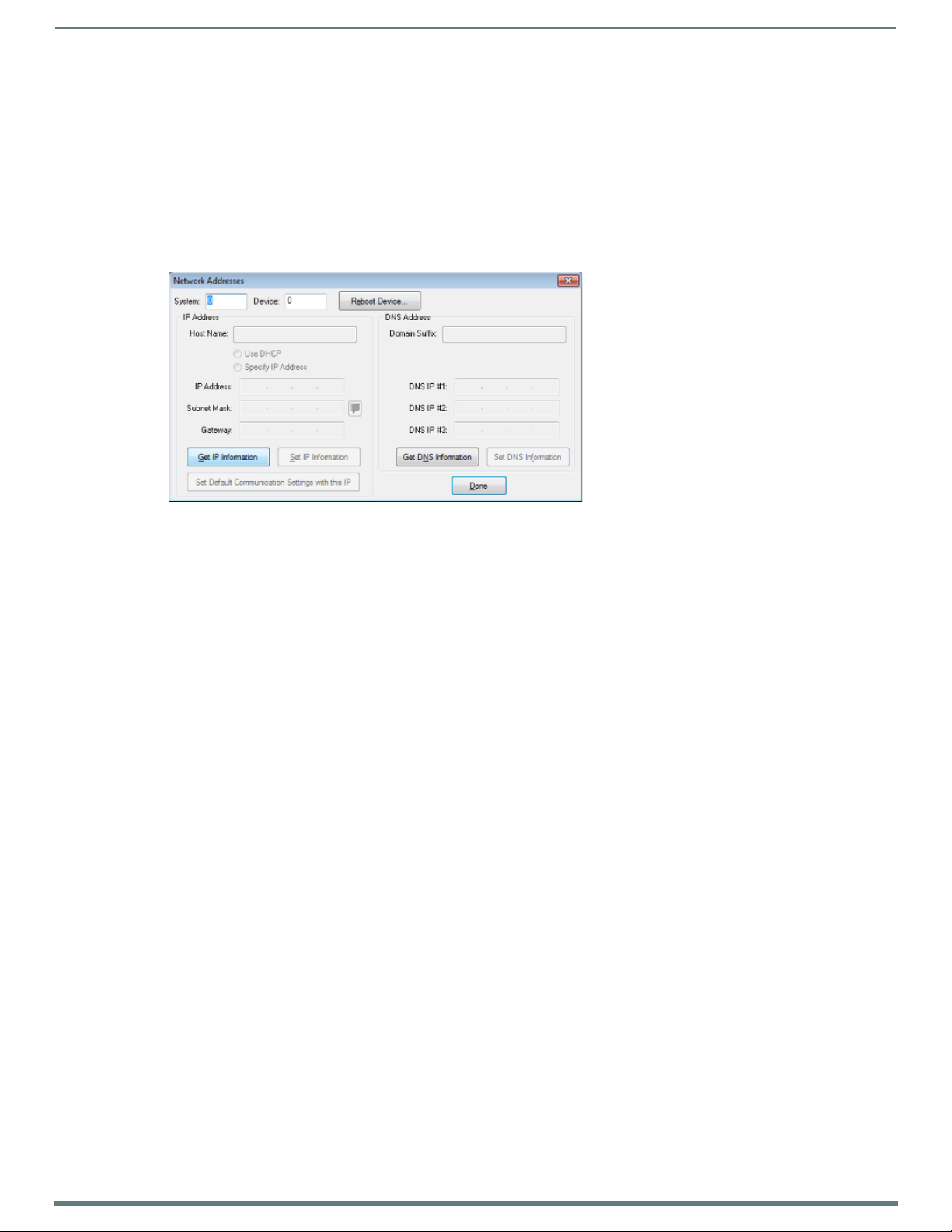
Initial Configuration
23
NX-Series Controllers - WebConsole & Programming Guide
7. Repeat steps 1 - 5 from the previous section, but rather than selecting the USB tab, select Network and edit the settings to
match the IP address you are using (Static or Dynamic).
8. If you want the Master to require authentication for access, enter a User Name and Password in the provided fields to secure
the Master.
9. Click the OK to close all dialogs and return to the main application.
Obtaining the NX Controller’s IP Address (using DHCP)
NOTE: Verify there is an active LAN connection on the NX controller’s LAN port before beginning these procedures.
1. In NetLinx Studio, select Diagnostics > Network Addresses from the Main menu to access the Network Addresses dialog
(FIG. 12).
FIG. 12
2. Verify that both the System number corresponds to the System value previously assigned within the Device Addressing tab
NOTE: The system value must correspond to the Device Address entered in the Device Addressing dialog. Refer to the Manage System
- System Number section on page 46 for more detailed instructions on setting a system value.
3. Click Ge t I P Information to enable the Use DHCP and Specify IP Address options.
4. Select Use DHCP.
NOTE: DO NOT enter ANY IP information at this time; this step only gets the System Master to recognize that it should begin using an
obtained DHCP Address.
5. Click Reboot Device.
6. After the device has booted, repeat steps 1-3.
7. Note the obtained IP address (read-only). This information is later entered into the Communication Settings dialog and used
NOTE: If the IP Address field is empty, give the Master a few minutes to negotiate a DHCP Address with the DHCP Server, and try
again. The DHCP Server can take anywhere from a few seconds to a few minutes to provide the Master with an IP address.
NOTE: Verify that these IP values are also entered into the related fields within either the IP Settings section of the System
Connection page (on the touch panel) or within the Address field on the web browser.
8. Click Done to close the dialog.
NOTE: On the front panel of the NetLinx Master, the STATUS and OUTPUT LEDs should begin to alternately blink during the
incorporation. Wait until the STATUS LED is the only LED to blink.
Complete the communication process by continuing on to the Communicating via IP Address section on page 25.
NetLinx Studio: Network Addresses dialog
and that zero (0) is entered into the Device field.
by NetLinx Studio to communicate to the NX controller via an IP. This add ress is reserved by the DHCP server and then given to
the Master.
Page 24
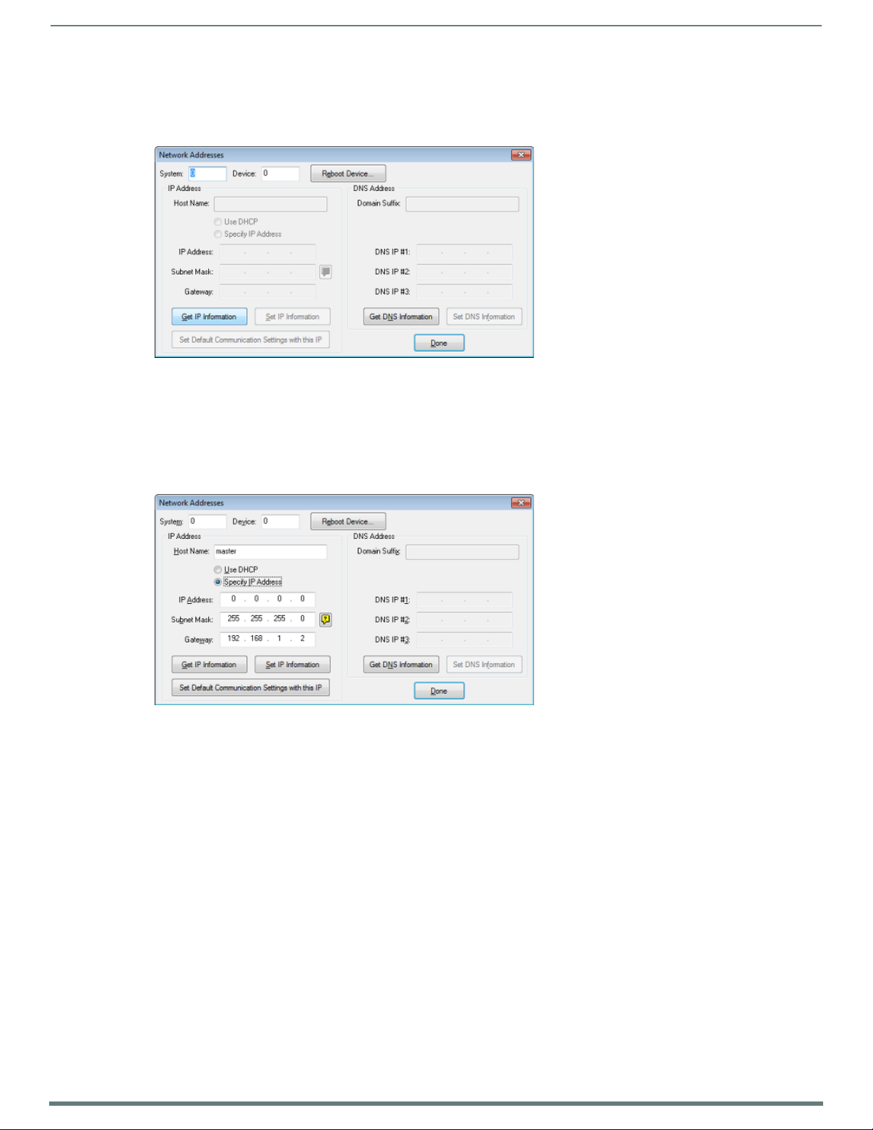
Initial Configuration
24
NX-Series Controllers - WebConsole & Programming Guide
Assigning a Static IP to the NX Controller
NOTE: Verify there is an active LAN connection on the LAN port of the Master before beginning these procedures.
1. In NetLinx Studio, select Diagnostics > Network Addresses to open the Network Addresses dialog (FIG. 13):
FIG. 13
2. Verify that both the System number corresponds to the System value previously assigned within the Device Addressing tab
NOTE: The system value must correspond to the Device Address previously entered in the Device Addressing tab. Refer to the Manage
System - System Number section on page 46 for more detailed instructions on setting a system value.
3. Click the Ge t I P Information button to enable the Use DHCP and Specify IP Address options.
4. Select Specif y IP Address to enable the IP fields for editing (FIG. 14):
FIG. 14 NetLinx Studio: Network Addresses dialog (Specify IP Address)
5. Enter the IP Address, Subnet Mask, and Ga t e w a y information into their respective fields (as defined by the System
NOTE: Verify that these IP values are also entered into the related fields within either the IP Settings section of the System
Connection page (on the touch panel) or within the Address field on the web browser.
6. Click Set IP Information to cause the on-board Master to retain this new IP address.
7. Click Reboot Master.
8. Click Done to close the dialog.
NOTE: On the front panel of the NetLinx Master, the STATUS and OUTPUT LEDs should begin to alternately blink during the
incorporation. Wait until the STATUS LED is the only LED to blink.
Complete the communication process by continuing on to the Communicating via IP Address section on page 25.
NetLinx Studio: Network Addresses dialog
and that zero (0) is entered into the Device field.
Administrator).
Page 25
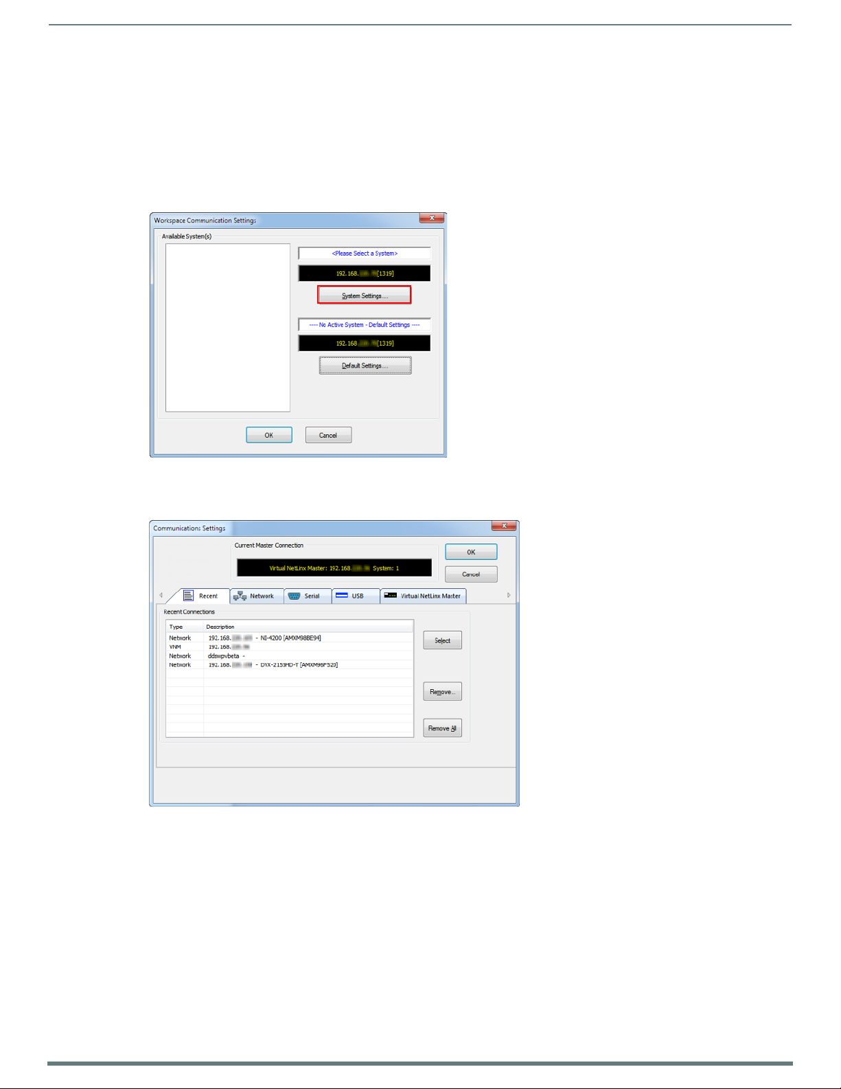
Initial Configuration
25
NX-Series Controllers - WebConsole & Programming Guide
Communicating via IP Address
Whether the on-board Master’s IP address was set or obtained via DHCP, use the IP address information from the Network
Addresses dialog to establish communication via the LAN-connected Master.
1. Use NetLinx Studio to obtain the IP address of the NX controller. If you do not have an IP address, follow the steps outlined in
either the Obtaining the NX Controller’s IP Address (using DHCP) section on page 23, or the Assigning a Static IP to the NX
Controller section on page 24.
2. Select Settings > Workspace Communication Settings from the Main menu to open the Workspace Communication Settings
dialog (FIG. 15):
FIG. 15
3. Click System Settings to open the Communications Settings dialog. If you do not have a system selected, click the Default
FIG. 16 NetLinx Studio - Communication Settings dialog (TCP/IP selected)
NetLinx Studio - Workspace Communication Settings dialog
Settings button (FIG. 16).
Page 26
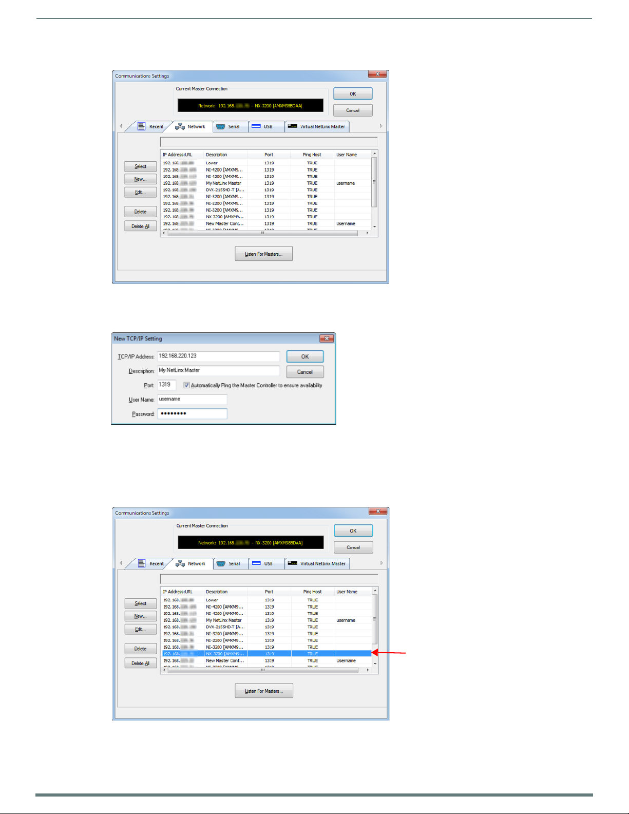
26
NX-Series Controllers - WebConsole & Programming Guide
4. Select the Network tab (FIG. 17).
Initial Configuration
FIG. 17
Communications Settings dialog - Network tab
5. Click New to open the New TCP/IP Setting dialog. In this dialog, you can enter both a previously obtained DHCP or static IP
address and an associated Description for the connection into their respective fields. (FIG. 18):
FIG. 18 NetLinx Studio - New TCP/IP Setting dialog
Verify that the Automatically Ping the Master Controller to ensure availability option is selected to make sure the Master is
initially responding on-line before establishing full communication.
If the authentication is required for connecting to the Master at this address, enter a User Name and Password in the text
fields provided.
6. Click OK to close the New TCP/IP Settings dialog and return to the Communication Settings dialog: (FIG. 19).
FIG. 19 NetLinx Studio - Communication Settings dialog
a. Click on the new IP address entry in the List of Addresses window
b. Click Select to use the selected IP address as the current IP address.
Page 27

Initial Configuration
27
NX-Series Controllers - WebConsole & Programming Guide
7. Click OK to save your newly entered information and close the Communication Settings dialog and return to the
Communication Settings dialog. Note the selected IP address is indicated in the Configuration field (FIG. 20):
FIG. 20
NetLinx Studio - Communication Settings dialog (Current Master Connection field indicating the selected IP address)
8. Click OK to begin the communication process to your Master (and close the dialog).
If you are currently connected to a Master, a pop-up asks whether you would want to stop communication to the current
Master and apply the new settings.
Click Yes to interrupt the current communication from the Master and apply the new settings.
NOTE: On the front panel of the NetLinx Master, the STATUS and OUTPUT LEDs should begin to alternately blink during the
incorporation. Wait until the STATUS LED is the only LED to blink.
9. Click the OnLine Tree tab in the Workspace window to view the devices on the System. The default System value is one (1).
10. Right-click the associated System number and select Refresh System. This establishes a new connection to the specified
System and populates the list with devices on that system. The communication method is then highlighted in green on the
bottom of the NetLinx Studio window.
NOTE: If the connection fails to establish, a Connection Failed dialog appears. Try selecting a different IP address if communication
fails. Press the Retry button to reconnect using the same communication parameters. Press the Change button to alter your
communication parameters and repeat the steps above.
Page 28
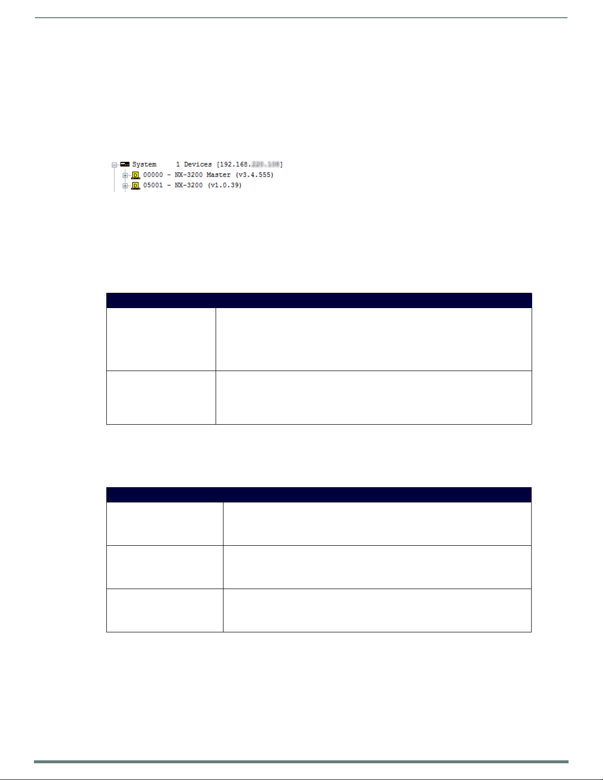
28
NX-Series Controllers - WebConsole & Programming Guide
Upgrading Firmware
Overview
The basic process of upgrading firmware on NX-series controllers involves downloading the latest firmware files from
www.amx.com and using NetLinx Studio to transfer the files to a t arget NX contro ller.
Use the OnLine Device tree in NetLinx Studio to view the firmware files currently loaded on the Central Controller. FIG. 21 shows an
example OnLine Tree indicating an NX-3200:
Upgrading Firmware
FIG. 21
While the method of upgrading firmware f iles is the same for all Central Controllers, there are some specific points relative to the
specific model and type of controller that must be noted:
NetLinx Studio - Sample OnLine Tree
NX Controllers - Firmware Files
NX controllers contain two devices (NX Master and Device Controller), each of which require a separate firmware (*.kit) file.
The NX Master firmware file is not the same as the Device Controller firmware file. These two devices must be kept at compatible
firmware versions for proper operation. Therefore, both f iles should be used when upgrading any firmware associated with the
Integrated Controllers.
NX Controllers - Firmware Files
NX Master Firmware The on-board NX Master is listed first in the OnLine Tree as
Device Controller Firmware The Device Controller is listed next as "05001 NX-XXXX (<firmware version>)"
"00000 NX Master (<firmware version>)"
For example, the NX Master in FIG. 21 above is "00000 - NX-3200 Master (v3.4.555)".
•"00000" represents Device ID 0, which is reserved for the Master
• The number in parenthesis (in this case "v3.4.555") is the current NX Master firmware
version.
For example, the Device Controller in FIG. 21 above is "05001 - NX-3200 (v1.0.35)".
•"05001" represents Device ID 5001, which is reserved for the Device Control ports.
• The number in parenthesis (in this case "v1.0.35") is the current Device Controller firmware
version.
Enova DVX
Enova DVX All-In-One Presentation Switchers contain three devices (NX Master, Device Controller, and A/V Switcher/ Scaler), each
of which require a separate Kit file. These three devices must be kept at compatible firmware versions for proper operation.
Therefore, all three files should be used when upgrading any firmware associated with the Enova DVX All-In-One Presentation
Switchers.
DVX Controllers - Firmware Files
NX Master Firmware The on-board NX Master is listed first in the Online Tree as
Device Controller Firmware The Device Controller is listed next as
A/V Switcher/Scaler Firmware The A/V Switcher/Scaler is listed third as
"00000 NX Master (<firmware version>)"
• "00000" represents Device ID 0, which is reserved for the Master
• The number in parenthesis is the current Master firmware version.
"05001 NX-XXXX (<f irmware version>)"
• "05001" represents Device ID 5001, which is reserved for the Device Control ports.
• The number in parenthesis is the current Device Controller firmware version.
"05002 NX-XXXX (<firmware version>)"
• "05002" represents Device ID 5002, which is reserved for the A/V Switcher/Scaler.
• The number in parenthesis is the current Device Controller firmware version.
Page 29

Upgrading Firmware
29
NX-Series Controllers - WebConsole & Programming Guide
Before You Start
1. Verify you have the latest version of the NetLinx Studio application installed on your PC.
NetLinx Studio is available to download from www.amx.com. Lo gi n to do wnload the latest version. Alternatively, if it is already
installed, use the Web Update option in NetLinx Studio’s Help menu to obtain the latest version.
The default location for the NetLinx Studio application is Start > Programs > AMX Control Disc > NetLinx Studio > NetLinx
Studi o.
2. Verify that a LAN cable is connected from the controller to the LAN Hub.
3. Verify that the controller is powered on.
4. Connect to the controller via IP address.
5. Establish what version of f irmware is currently loaded on the controller (see Verifying the Current Firmware Version below).
Verifying the Current Firmware Version
Use the OnLine Tree in NetLinx Studio (see FIG. 21 on page 28) to verify which version of each firmware file is currently installed.
NOTE: These steps assume that you have already established a connection with the target Central Controller (see the Initial
Configuration section on page 19 for details).
1. In NetLinx Studio, click on the OnLine Tree tab (in the Workspace Bar) to view the devices on the System.
2. Click Display and select Refresh System from the context menu. This establishes a new connection to the System and
populates the device tree with devices on that system.
3. After the Communication Verification dialog indicates active communication between the PC and the Central Controller, verify
the Central Controller and associated devices are listed in the OnLine Tree.
4. Check the appropriate product page on www.amx.com for the latest NX Master and Device Controller firmware files for your
device.
If necessary, follow the procedures outlined in the following sections to obtain these firmware (*.kit) files from www.amx.com and
then transfer the new firmware files to the device.
Downloading the Latest Firmware Files from www.amx.com
NetLinx Integrated Controllers
NX-series Controllers require two firmware (*.kit) files: Master firmware and Device firmware. The Master firmware file is not the
same as the Device firmware file.
Both f iles should be used when upgrading any firmware associated with the Integrated Controllers.
IMPORTANT: The process of downloading and transferring firmware files is the same for all types of firmware. However, it is
important that the firmware files are upgraded in specific following order for NX-series Controllers (see the Required Order of
Firmware Updates section on page 31).
Master and Device Firmware Kit Files for NX-Series Controllers
Below is a table outlining the Master and Device Firmware (*.kit) files used by NetLinx Integrated Controllers:
Master and Device Firmware Files for NX-Series Controllers
NX-4200 / 3200 /
2200 / 1200
NOTE: The HTTP f irmware kit enables you to upgrade firmware via an HTTP server. Follow the same steps in NetLinx Studio as you
would with a typical firmware upgrade. Upgrading firmware via HTTP server is typically much faster than upgrading with the standard
firmware kit files. See the Upgrading Firmware via NetLinx Studio section on page 31 for more information.
Master Firmware: SW2106_NX_X200_Master_vx_x_xxx.kit
HTTP Firmware Kit: SW2106_NX_X200_10x_vx_x_xxx-http.kit
Page 30
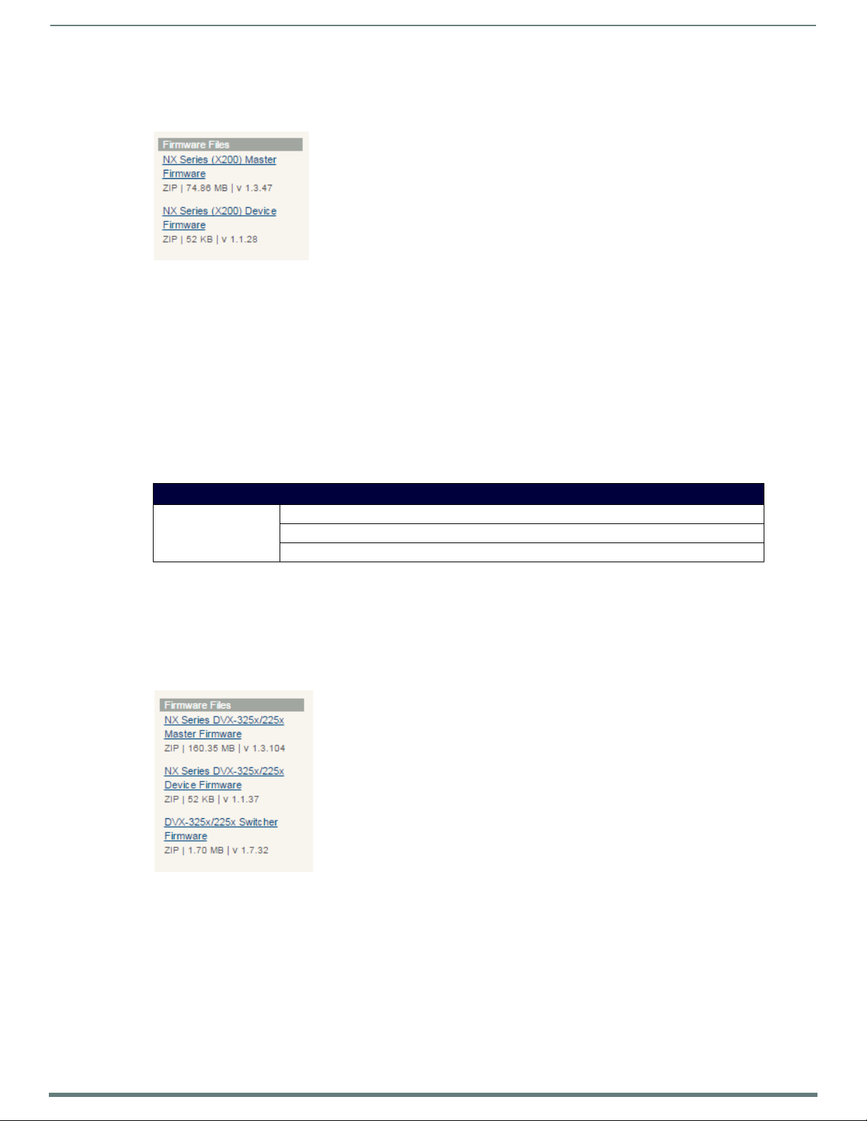
Upgrading Firmware
30
NX-Series Controllers - WebConsole & Programming Guide
Downloading NX-Series Controller Firmware Files on www.amx.com
Visit the appropriate product page on www.amx.com for the latest NX Master and Device Controller firmware (*.kit) files for your NX
controller. Firmware f ile links are available along the right-side of the cat alog page (FIG. 22):
FIG. 22 www.amx.com - sample NX Controller Firmware File links
Firmware f iles are b undled in a ZIP f ile, alo ng with a Readme.TXT file that provides details on this firmware release.
1. Accept the AMX Licensing Agreement.
2. Download the ZIP f ile and unzip the contents to a known location.
Enova DVX All-In-One Presentation Switchers
Enova DVX All-In-One Presentation Switchers require an additional Switcher Firmware f ile for the built-in switcher. ALL f iles shou ld
be used when upgrading any firmware associated with the Integrated Controllers.
NOTE: The process of downloading and transferring f irmware files is the same for all types of firmware. However, it is important that
the firmware files are upgraded in specific following order for DVX Controllers (see the Required Order of Firmware Updates for DVX
Controllers section on page 31).
Master, Switcher and Device Firmware Files for Enova DVX All-In-One Presentation Switchers
Below is a table outlining the Master, Device, and Switcher f irmware (*.kit) files used by Enova DVX Controllers:
Master Firmware Kit File Usage for Enova DVX Controllers
DVX-3250/3255/3256
2250/2255/2210HD
Master Firmware: SW2106_NX-X200_Master_v1_x_xxx.kit
Device Firmware: SW2106_NX_X200_Device_v1_x_xx.kit
HTTP Firmware Kit: SW2106_NX_X200_10x_vx_x_xxx-http.kit
NOTE: The HTTP f irmware kit enables you to upgrade firmware via an HTTP server. Follow the same steps in NetLinx Studio as you
would with a typical firmware upgrade. Upgrading firmware via HTTP server is typically much faster than upgrading with the standard
firmware kit files. See the Upgrading Firmware via NetLinx Studio section on page 31 for more information.
Downloading Enova DVX Firmware Files on www.amx.com
Visit the appropriate product page on www.amx.com for the latest NX Master, Device Controller, and A/V Switcher/Scaler firmware
(*.kit) f iles for yo ur Enova DVX All-In-One Presentation Switcher. Firmware f ile links are avai lable along the right-side of the catalog
page (FIG. 23):
FIG. 23 www.amx.com - sample Enova DVX Firmware File links
Firmware f iles are b undled in a ZIP f ile, alo ng with a Readme.TXT file that provides details on this firmware release.
1. Accept the AMX Licensing Agreement.
2. Download the ZIP f ile and unzip the contents to a known location.
Page 31

Upgrading Firmware
31
NX-Series Controllers - WebConsole & Programming Guide
Master and Device Firmware Kit Files for Massio ControlPads
Below is a table outlining the Master and Device Firmware (*.kit) f iles used by Massio ControlPads:
Master and Device Firmware Files for Massio ControlPads
MCP-106/108 Master Firmware: SW2102_MCP_10x_vx_x_xxx.kit
Device Firmware: SW2102_MCP_10x_Device_vx_xx_x.kit
HTTP Firmware Kit: SW2102_MCP_10x_vx_x_xxx-http.kit
NOTE: The HTTP f irmware kit enables you to upgrade firmware via an HTTP server. Upgrading a Massio ControlPad to firmware
version 1.4 or higher requires the current f irmware version on the ControlPad to be version 1.3.106 or higher. Follow the same steps
in NetLinx Studio as you would with a typical firmware upgrade. Upgrading f irmware via HTTP server is typically much faster than
upgrading with the standard firmware kit files. See the Upgrading Firmware via NetLinx Studio section on page 31 for more
information.
Required Order of Firmware Updates
The Upgrading Firmware via NetLinx Studio instructions (below) apply equally to all types of f irmware files. However, it is important
that the firmware files are upgraded in the following order:
1. First, upgrade the Master firmware.
2. When that process is complete, upgrade the Device firmware.
IMPORTANT: ALWAYS consult the Readme.TXT file bundled with the firmware file for any special instructions before upgrading to a
newer firmware version. If no specif ics are provided, use the order provided above.
Required Order of Firmware Updates for DVX Controllers
Upgrade firmware in the following order:
1. First, upgrade the A/V Switcher/Scaler firmware.
2. When that process is complete, upgrade the Master firmware.
3. When that process is complete, upgrade the Device firmware.
IMPORTANT: ALWAYS consult the Readme.TXT file bundled with the firmware file for any special instructions before upgrading to a
newer firmware version. If no specif ics are provided, use the order provided above.
Upgrading Firmware via USB
All X-Series controllers support firmware upgrades via a USB solid-state drive. You can upgrade via USB by selecting the
appropriate .kit file and initiating the upgrade via telnet. The “IMPORT KIT” telnet command causes the controller to search the
attached USB drive for all valid .kit f iles and display the f iles as a list. From here you ca n s elect the .kit f ile to u se an d initiate the
firmware upgrade. See the IMPORT KIT section on page 107 for more information.
Upgrading Firmware via NetLinx Studio
NOTE: These steps assume that you have already established a connection with the target Central Controller (IP connection is
preferred.) See the Initial Configuration section on page 19 for details.
1. In NetLinx Studio. click on the OnLine Tree tab (in the Workspace Bar) to view the devices on the System.
2. In the OnLine Tree tab, click Display and select Refresh System from the context menu. Doing so establishes a new connection
to the System and populates the device tree with devices on that system.
3. After the Communication Verification dialog indicates active communication between the PC and the Central Controller, verify
the Master and associated devices (including the Device Controller) are listed in the OnLine Tree.
4. In NetLinx Studio, select Too l s > Firmware Transfers > Send to NetLinx Device (FIG. 24):
FIG. 24 NetLinx Studio - Tools > Firmware Transfers > Send to NetLinx Device
This step opens the Send to NetLinx Device dialog.
Page 32

Upgrading Firmware
32
NX-Series Controllers - WebConsole & Programming Guide
5. Click the Browse button (...) to locate and select the f irmware (*.kit) f ile that will be transferred, in the Browse for Folders
dialo g (FIG. 25):
FIG. 25
NetLinx Studio - Send to NetLinx Device dialog
The selected file is indicated in the Files window.
6. Verify the target’s System number matches the value listed within the active System folder in the OnLine Tree.
The Device number is always 0 for the NX Master.
Note that the Port field is disabled (FIG. 26).
FIG. 26 Send to NetLinx Device dialog (showing on-board NX Master firmware update)
7. Click Send to begin the transfer. The file transfer progress is indicated in the Progress section of the dialog. The Master
reboots when the f ile transfer is complete.
8. Click Close once the Master is finished rebooting.
9. In the OnLine Tree, right-click on the Master and select Refresh System. This establishes a new connection and refreshes the
device list and their firmware versions in your system.
Page 33

Upgrading Firmware
33
NX-Series Controllers - WebConsole & Programming Guide
Once the process is complete, you can upgrade the remaining firmware files. All device files must be kept at compatible firmware
versions for proper operation. Therefore, all files should be used when upgrading any firmware associated with the Integrated
Controllers.
Be sure to follow the required order for installing firmware f iles. See the Required Order of Firmware Updates section on page 31 for
more information.
Resetting the Factory Default System and Device Values
1. In NetLinx Studio, access the Device Addressing dialog:
Right-click on any system device listed in the Workspace and select Device Addressing.
Select Diagnostics > Device Addressing from the Main menu.
2. Click the Set Device/System to Factory Default button (FIG. 27):
FIG. 27
NOTE: By setting the system to its default value (#1), Modero panels that were set to connect to the Master on another System value
will not appear in the OnLine Tree tab of the Workspace window. For example: A Modero touch panel was previously set to System #2.
The system is then reset to its default setting of System #1 and then refreshed from within the Workspace window. The panel will not
reappear until the system is changed (from within the System Connection page on the Modero) to match the new value and both the
Master and panel are rebooted.
3. Click Done to close the Device Addressing dialog.
4. Click Reboot (from the Tools > Reboot the Master Controller dialog) and wait for the System Master to reboot.
NOTE: The STATUS and OUTPUT LEDs should begin to alternately blink during the incorporation. Wait until the STATUS LED is the only
LED to blink.
5. Click Done. Wait until the Master Reboot Status field reads *Reboot of System Complete*.
6. Click the OnLine Tree tab in the Workspace window to view the devices on the System.
7. Right-click the associated System number (or anywhere within the tab itself) and select Refresh System. This establishes a
8. Use Ctrl+S to save these changes to your NetLinx Project.
Device Addressing dialog
This resets both the system value and device addresses (for definable devices) to their factory default settings. The system
information (in the OnLine Tree tab of the Workspace window) refreshes and then displays the new information.
new connection to the specif ied System and populates the list with devices on that system.
Page 34

34
NX-Series Controllers - WebConsole & Programming Guide
On-Board WebConsole User Interface
WebConsole UI Overview
NetLinx Masters have a built-in System Configuration interface that allows you to make various configuration settings via a web
browser on any PC that has access to the Master. The System Configuration interface (an on-board web conf iguration) contains a
comprehensive set of web pages that can be used during setup to manage your system’s network, security, and system needs, as
well as configure its inputs and outpu ts while executing switches (FIG. 28).
On-Board WebConsole User Interface
FIG. 28
WebConsole - Web Controls page (initial view)
The WebConsole offers five primary sections from a menu located at the top of the page, indicated by five menu options across the
top of the main page (FIG. 29):
FIG. 29 System Configuration Menu Options
Home: This option appears when you access the System Configuration page. Use these options to view any connected
device or access a module.
Network: Click to access the Network Settings for the Master. The options on these pages enable you to view and modify
the IPv4 and IPv6 network settings and the clock settings for the system (see the WebConsole - Network Options section
on page 36).
Security: Click to access the System Security page. The options in this page allow you to configure various aspects of
NetLinx System and Security on the Master, including network configuration and creating users and roles (see the
WebConsole - Security Options section on page 41).
System: Click to access the System Details page. The options on this page allow you to view and configure various aspects
of the NetLinx System (see the WebConsole - System Options section on page 57).
Modules: Click to access several different device-related pages (see the WebConsole - Modules Opt ions section on page 59).
Switcher: Click to access the Enova Switcher Configuration page (see the WebConsole - Switching Options section on
page 67). This page only appears for Enova devices.
From the Home page, Web Control options become available (e.g., RMS, Virtual Keypad, and device details pages for any connected
devices).
System Configuration Interface Tips:
It is recommended that you use the latest, industry accepted version of HTML5 browsers. If a browser is inconsistent,
upgrade or try a different browser. To-date, browsers tested include Google Chrome (preferred), Mozilla Firefox, Apple
Safari, and Microsoft Internet Explorer 10+/Edge.
To access the interface after initial setup, simply type the integrated Master ’s IP address in the address bar of the browser
and press the Enter key. On the DVX, DGX, and NX-4200, the IP address is available on the front panel display.
Some devices run on a secured file-system. As such, file-system operations (e.g., Load and Save operations) may not be
supported by the device’s default capabilities and may require downloading a file manager application.
When selecting Inputs and Outputs for switches – you may select an input followed by multiple outputs, but only one input
is select ab le i f you select an ou t pu t f irst.
Inputs and Outputs can only have one name each, regardless of whether the name is set via the Video tab or the Audio tab
in the Configuration page (or via NetLinx SEND_COMMANDs VIDIN_NAME, VIDOUT_NAME, AUDIN_NAME, AUDOUT_NAME).
Inputs and Outputs may be named independently.
Page 35

On-Board WebConsole User Interface
35
NX-Series Controllers - WebConsole & Programming Guide
Accessing the WebConsole
From any PC that has access to the LAN that the target Master resides on:
1. Open a web browser and type the IP Address of the target Master in the Address Bar.
2. Press Enter to access WebConsole for that Master. The initial view is the Web Control page (FIG. 28).
When using the Microsoft Internet Explorer browser in Windows 8, you may not be able to login and connect to the Master via the
WebConsole. If you cannot login and connect, try any of the following options:
Shift+Right-click Internet Explorer icon and select Run as administrator.
Select Internet Options | Advanced | Security Settings, and check Enable Enhanced Protection Mode. A Windows 8 restart
will be required.
Use the Master’s Hostname instead of its IP numeric address to enter the URL (e.g.: http://AMXM98A1A2B rather than
http://192.168.1.123)
Use a non-Windows 8 device if Internet Explorer 10+ is required.
Default User Names and Passwords
The following table lists the default user names and passwords for accessing the NX-series controllers through NetLinx Studio or
the WebConsole.
Default User Names and Passwords
User Name Password
NetLinx Studio netlinx password
WebConsole administrator password
Page 36

36
NX-Series Controllers - WebConsole & Programming Guide
WebConsole - Network Options
Network Overview
The Network page (FIG. 30) is accessed by clicking Network on the page’s main heading. This page allows you to view and
configure various aspects of the Master’s network:
IPv4 Setup - Options on this page allow you to view/change the Master’s IP and DNS add ress information. See the Network
- IPv4 Setup section on page 37 for details.
IPv6 Setup - This page allows you to view the IPv6 address, subnet mask, and gateway for the Master. See the Network -
IPv6 Setup section on page 38 for details.
Date/Time - Options on this page allow you to enable/disable using a network time source and provide access to Daylight
Saving configuration and which NIST servers to use as a reference. See the Network - Date/Time section on page 38 for
details.
WebConsole - Network Options
FIG. 30
Network page
Page 37

WebConsole - Network Options
37
NX-Series Controllers - WebConsole & Programming Guide
Network - IPv4 Setup
Click IPv4 Setup to access the IPv4 page (FIG. 31) and view and conf igure IP and DNS addresses for the Master. Use the options on
this page to view/edit the Master’s network settings. A user can only modify the information on this page if it is assigned a Role that
includes the Network Configuration permission. Without the proper permission, a user can only view the information on this page.
FIG. 31
Network - IPv4 Setup page
IPv4 Options
The IPv4 options are described in the following table:
IPv4 Options
Option Description
IP Address: This section enables you to set IP information for the Master’s network.
IP Hostname Enter the IP host name in this field.
DHCP/Specific IP
Address
IP Address Enter the IPv4 address in this field. This field is only available if you select Specific IP Address.
Subnet Mask Enter the IPv4 subnet mask in this field. This field is only available if you select Specific IP Address.
Gateway Enter the gateway IPv4 address in this field. This field is only available if you select Specific IP Address.
DNS Address: This section enables you to set DNS information for the Master’s network.
Domain Enter the domain name of the DNS server in this field.
DNS IP Enter up to three DNS server addresses in the provided fields.
Zero-Config
Networking
NetLinx Discovery
Protocol (NDP)
Use the b uttons to select a DHCP or static IP address. Additional options in this area become available if you select
Specific IP Address.
Use the buttons to activate zero-config networking functionality on the Master’s network. Zero-config networking
provides the ability to automatically discover devices that are present on the LAN. By default, zeroconf is enabled
(On option selected). With zeroconf enabled, the Master's web interface will be registered via zeroconf and can be
viewed through a zeroconf browser plug-in such as Bonjour for IE.
Use the bu ttons to indicate whether you want the Master to search for any NDP-capable devices currently
connected to the Master.
Page 38

WebConsole - Network Options
38
NX-Series Controllers - WebConsole & Programming Guide
Network - IPv6 Setup
Click IPv6 Setup to access the IPv6 page (FIG. 32) and view the IPv6 address, subnet mask, and gateway for the Master. This
information is view-only.
FIG. 32
Network - IPv6 Setup page
Network - Date/Time
Click the Date/Time link (on the Network page) to access the Date/Time page (FIG. 33). The options on this page allow you to
enable/disable using a network time source and provide access to Daylight Saving configuration and which NIST servers to use as
a reference.
FIG. 33 Network - Date/Time page
The Clock Manager Options are separated into three areas:
Clock Manager - The Clock Manager allows you to set the Clock Manager Mode (Network Time or Stand Alone).
Daylight Savings Time Manager - The Daylight Savings Time Manager allows you to specify how and when to implement
Daylight Savings rules on the clock.
NIST Server Manager - The NIST Server Manager allows you to connect to a specific NIST (Internet Time Service) Server.
Page 39

WebConsole - Network Options
39
NX-Series Controllers - WebConsole & Programming Guide
Setting the Mode for the Clock Manager
1. In the Manage System tab (FIG. 33), select a Time Sync option.
Network Time: This option allows the Master to manage it’s clock by connecting to a NIST (Internet Time Service) Server.
When this option is selected, the Master will connect to the default NIST Server to get date and time information.
You can select a different NIST Server (or specify the IP Address of a known NIST Server) in the NIST Server Manager
section (see the Selecting a Custom NIST Server section on page 39).
Stand Alone: This option lets the Master use its own internal clock. When this option is selected, two additional fields are
available on this tab:
Date - Enter the current date in this field (mm/dd/yyyy).
Time - Enter the current time in these fields (Hours/Minutes/Seconds).
2. Click Accept to save these settings to the Master.
Setting Daylight Savings Rules
1. In the Daylight Savings Time Manager section (FIG. 34), enable Daylight Savings mode by clicking the On button. Clicking On
reveals additional Daylight Savings options.
FIG. 34
Date/Time Options - Daylight Savings Time Manager
2. Use the Offset drop-down menus to adjust the amount of time (hours and minutes) to offset Daylight Savings. By default, the
offset is set to 1 hour.
NOTE: Although most places that support Daylight Savings usually adjust the local time by one hour this doesn't cover all locations.
To provide flexibility for such locations it is possible to configure a different daylight savings time offset.
3. Use the St arts fields to specify when Daylight Savings should st art. The Starts rules i nclude:
Select Fixed to specify the calendar date when the rule applies as a specific date ("March 21"). When Fixed is selected, use
the Day, Month, Hours, and Minutes fields to specify the date and time (hh:mm) to start Daylight Savings time.
Select by Occurrence to specify the calendar date when the rule applies as a heuristic, ("the 3rd Sunday in March"). When
by Occurrence is selected, use the Wk of the Month, Day, Month, Hours, and Minutes f ields to specify the occurrence to
start Daylight Savings time.
The range for Wk of the Month is 1 through Last, where Last indicates the last occurrence of a particular day of the
month. This is to accommodate months that include four weeks as well as those that include five.
4. Use the Ends fields to specify when Daylight Savings should end. The End s r ules matc h the Start rules, a nd fo llow the same
logic. Select Fixed or by Occurrence, and specify the End date/time information accordingly.
5. Click Accept to save these settings to the Master.
Selecting a Custom NIST Server
FIG. 35 Date/Time Options - NIST Server Manager
1. In the NIST Server Manager section (FIG. 35), use the option buttons to select one of the NIST Servers in the list.
2. Click Accept to save the selection to the Master.
Page 40

40
NX-Series Controllers - WebConsole & Programming Guide
Adding a Custom NIST Server to the List
1. Click Add Server. The Add New Server dialog opens (FIG. 36).
WebConsole - Network Options
FIG. 36
2. In the New Server URL f ield, enter the URL of the NIST Server. The URL is used only to help you manage entries, and is not
3. Enter the NIST Server’s IP Address in the New IP field. This is used internally and must be a valid IP address.
4. Enter the NIST Server’s location in the New Location f ield. This is used only to help the user manage entries and it is not
5. Click Accept to save these settings to the Master.
Add New Server dialog
verified or used internally by the clock manager.
NOTE: The strings entered into the URL and Location fields are not used to connect to NIST Servers. The IP Address (entered
into the IP field) specifies the NIST Server(s) that will be used. As stated above, the address entered into the IP field must be
must be a valid IP address (not a URL).
verified or used internally by the clock manager.
Removing an NIST Server From the List
1. Click on the Remove (x) button to the right of a user-added NIST Server in the NIST Server Manager list.
2. Click Accept to save these settings to the Master.
NOTE: The built-in entries cannot be removed.
Clock Manager NetLinx Programming API
Refer to Appendix C: Clock Manager NetLinx Programming API section on page 145 for a listing and description of the Types/
Constants and Library Calls that are included in the NetLinx.AXI to support Clock Manager functions.
Page 41

41
NX-Series Controllers - WebConsole & Programming Guide
WebConsole - Security Options
Security Overview
The Security page is accessed by clicking Security on the page’s main heading. This page allows you to view configure and modify
the Master’s security settings at three levels (System, Role, and User). See the Security Presets section on page 45 for more
information on the three presets.
System Level - changes made at this level affect the system globally. See the Security - General section on page 43 for
details.
Role Level - changes made at this level affect specific Roles. See the Security - Roles section on page 47 for details.
User Level - changes made at this level affect individual Users. See the Security - Users section on page 51 for details.
The default view for the option is System Security Settings (FIG. 37).
WebConsole - Security Options
FIG. 37
NOTE: By default, all System-level security options are disabled, except for Authentication On Server Ports, which requires a login for
access to the web or command line interface.
Additional security configuration options are available via Terminal/Telnet Commands. See the Accessing the Security
Configuration Options section on page 121.
System Security Settings
Login Rules
There is no limit to the number of concurrent logins allowed for a single user. This allows for the creation of a single user that is
provided to multiple ICSP devices (touch panels, for example) using the same login to obtain access to the Master.
For example, if you have 50 devices connected to a Master, you do no t have to create 50 individual user accounts, with one for each
device. Instead, you only need to create one which all 50 devices use for access.
The first layer of security for the Master is to prompt a user to enter a valid user name and password before gaining access to a
secured feature on the target Master.
Depending on the Security configuration, users may be prompted to enter a valid user name and password before gaining access to
various features of the WebConsole. User access is specified by the administrator in the Role and User Level pages of the Security
section.
NOTE: This user name and password information is also used by both G5 touch panels (within the System Connection firmware page)
and AMX software applications such as NetLinx Studio v 4.0 and above to communicate securely with a Master using encrypted
communication.
Page 42

WebConsole - Security Options
42
NX-Series Controllers - WebConsole & Programming Guide
User and Role Name Rules
User account and role names must follow these rules:
Case-sensitive
Must be between 4 and 20 alpha-numeric characters: A-Z, a-z, 0-9
The following characters are allowed: - _ . # and <space>.
Password Rules
The rules for changing a password vary according to the Password Complexity setting for the user. A user’s password complexity
can be set to Low, Medium, or High.
Low - Minimum length is 4 characters, and must be different from previous password.
Medium - Minimum length is 8 characters, must contain characters from 3 character classes listed in the table below, must
contain at least 4 changes from the previous password, and must be different from the previous 10 passwords.
High - Minimum length is 15 characters, must contain characters from all of the characters classes listed in the table below,
must contain at least 8 changes from the previous password, and must be different from the previous 30 passwords.
The requirements for each setting are listed in the following table:
Password Complexity Requirements
Requirement Low Medium High
Case Change Only No No Yes
Character Classes Required 0 3 4
Library Check No No Yes
Minimum Length 4 8 15
Palindrome Check No No Yes
Same Consecutive Characters No check 5 3
Similarity Check 1 4 8
User Name Check (straight or reversed) No Yes Yes
Different from Previous # of Passwords 1 10 30
The definitions of each requirement are listed below:
Case Change Only: A new password cannot differ from the previous passwords solely by a change in case (upper/lower)
Character Classes Required: A password must contain characters from a set number of character classes. See the
Character Classes table below for the list and definitions of character classes.
Library Check: The password cannot contain a word from a dictionary f ile supplied with the OS.
Minimum Length: The password must contain a minimum set number of characters.
Palindrome Check: The password does not contain a palindrome of a 7-letter length or greater.
Same Consecutive Characters: The password does not contain more than a set number of the same consecutive
characters.
Similarity Check: The password differs from the previous password by a set number of characters.
User Name Check: The password does not contain the user’s user name.
Different from Previous # of Passwords: The password differs from a set number of previous passwords.
The following table lists the characters available in each character class:
Character Classes
Character Class Example
Uppercase Letters A-Z
Lowercase Letters a-z
Numbers 0-9
Other Characters `~ ! @ # $ % ^ & * ( ) _ - + = { } [ ] \ | : ; " ' <> , . ?/ (including "space")
Page 43

WebConsole - Security Options
43
NX-Series Controllers - WebConsole & Programming Guide
Security - General
The General Security Settings page provides global permissions for various options that may be individually selected and applied to
all users. The Master provides 3 levels of security settings presets: Low, Medium, and High. The levels are simply presets of various
security settings. When a preset is selected, the settings are not applied until you click Accept. You can customize any settings as
needed on the security preset before accepting and applying the settings. The default for the settings will match the Low presets.
System Level Security - System Security Settings
Click the System Security Settings link to access the System Security Details page (FIG. 38). The options in this page allow you to
establish whether the Master will require a valid user name and password be entered prior to gaining access to the configuration
options.
FIG. 38
These are global options that enable or disable the login requirement for both users and roles.
System Security Settings
System Security Options
The System Security options are described in the following table:
System Security Options
Option Description
Security Presets The Master provides three levels of security setting presets: Low, Medium, and High. Each level is a preset of
Audit Log Select to enable/disable remote syslog. See the Audit Logs section on page 46 for more information.
Banner Display Select to turn on or turn off banner messages. Banners enable you to display pre- and post-login text in the
USB Host Port Select to enable all Type-A USB connectors on the Master.
Inactivity Timeout Select to enable the Master to log out a user after a defined period of inactivity. After enabling the inactivity
various security settings (see the Security Presets section on page 45 for more information.) When a preset is
selected, that setting is applied after clicking Accept.
NOTE: If a security preset is not selected, all subordinate options are grayed-out and not selectable, meaning
that the Master is completely unsecured and can be altered by any user (regardless of their rights).
WebConsole. See the Banners section on page 46 for more information.
timeout option, use the spin box to set the number of minutes before the timeout activates. You can set a timeout
in the range of 1 to 60 minutes. The default setting is 10 minutes. The timeout applies to Program Port, Telnet,
SSH, HTTP, and HTTPS sessions.
Page 44

WebConsole - Security Options
44
NX-Series Controllers - WebConsole & Programming Guide
System Security Options (Cont.)
Option Description
Password Expiration Select to force a user to change its password after a set period of time. After enabling the password expiration
Cryptography
Stre ngth :
Password Complexity Set the password complexity to Low, Medium, or High. When the password complexity level is raised from a lower
Lockout Access Select to enable a lock on a user account after a set number of failed logins. When enabled, use the Attempts spin
HTTP/HTTPS Select to enable HTTP and HTTPS access to the Master.
Telnet/SSH/SSH FTP
Access
options, use the spin box to set the interval for password expiration. You can set an amount of time in the range of
1 to 180 days. The default setting is 60 days.
NOTE: This option is only valid on locally-maintained accounts. When external LDAP is enabled, only the
administrator and device user accounts are affected.
Set the cryptography strength of the Master to Low or High. On the High setting, only FIPS 140-2 validated
binaries are used.
level to a higher level, the Master requires confirmation from the user. When the user conf irms the change, all
passwords are marked as expired on all local user accounts, and the passwords must be changed to meet the new
complexity requirements. Password complexity requirements are as follows:
• Low - Minimum length is 4 characters, and must be different from previous password.
• Medium - Minimum length is 8 characters, must contain characters from 3 of the following characters sets
(uppercase letters, lowercase letters, numbers, other characters), must contain at least 4 changes from the
previous password, and must be different from the previous 10 passwords.
• High - Minimum length is 15 characters, must contain characters from all of the following characters sets
(uppercase letters, lowercase letters, numbers, other characters), must contain at least 8 changes from the
previous password, and must be different from the previous 30 passwords.
NOTE: This option is only valid on locally-maintained accounts. When external LDAP is enabled, only the
administrator and device user accounts are affected.
box to set the number of login attempts allowed. Use the Lockout Duration options menu to indicate the amount of
time you want the lockout to last. The default setting is 60 minutes.
NOTE: This option is only valid on locally-maintained accounts. When external LDAP is enabled, only the
administrator user is affected.
HTTP: The port value used for unsecure HTTP Internet communication between the web browser’s UI and the
target Master. By disabling this port, the administrator (or other authorized user) can require that any consecutive
sessions between the UI and the target Master are done over a more secure HTTPS connection.
By default, the Master does not have security enabled and must be communicated with using http:// in the
Address field. The default port value is 80.
NOTE: One method of adding security to HTTP communication is to change the Port value. If the port value is
changed, any consecutive session to the target Master has to add the port value at the end of the address
(within the Address field). An example is if the port were changed to 99, the new address information would
be: http://192.192.192.192:99.
HTTPS:
The port value used by web browser to securely communicate between the web server UI and the target
Master. This port is also used to simultaneously encrypt this data using the SSL certif icate information on the
Master as a key.
This port is used not only used to communicate securely between the browser (using the web server UI) and the
Master using HTTPS but also provide a port for use by the SSL encryption key (embedded into the certificate).
Whereas SSL creates a secure connection between a client and a server, over which any amount of data can be
sent securely, HTTPS is designed to transmit individual messages securely. Therefore both HTTPS and SSL can be
seen as complementary and are configured to communicate over the same port on the Master. These two methods
of security and encryption are occurring simultaneously over this port as data is being transferred. The default
port value is 443.
Another method of adding security to HTTPS communication would be to change the port value. If the port
value is changed, any consecutive session to the target Master has to add the port value at the end of the
address (within the Address field). An example is if the port were changed to 99, the new address information
would be: http://192.192.192.192:99.
Select to enable Telnet, SSH, and SSH FTP access to the Master.
Te l ne t : The port value used for Telnet communication to the target Master. Enabling this feature allows future
communication with the Master via a separate Telnet application.
• The default port value for Telnet is 23.
• Refer to the NetLinx Security with a Terminal Connection section for more information on the related procedures.
SSH: The port value used for secure Telnet communication. A separate secure SSH Client would handle
communication over this port. When using a secure SSH login, the entire login session (including the transmission
of passwords) is encrypted; therefore it is secure method of preventing an external user from collecting
passwords.
•SSH version 2 is supported.
• The default port value is 22.
NOTE: If this port’s value is changed, make sure to use it within the Address f ield of the SSH Client
application.
Page 45

WebConsole - Security Options
45
NX-Series Controllers - WebConsole & Programming Guide
System Security Options (Cont.)
Option Description
FTP Access Select to enable FTP access to the Master. The default port value used for FTP communication is 21.
NOTE: This port can be disabled/enabled, but its value cannot be changed.
Authenticate on
Server Ports
Select to require user name and password authentication on Telnet, Program, and HTTP/HTTPS ports.
Authentication is always required on FTP/SFTP and SSH ports.
NOTE: If Authenticate on Server Ports is disabled but LDAP is enabled, a login is still required. If you do not
desire a login, LDAP must also be disabled.
Authenticate AMX
Devices On ICSLAN
Ports
ICSLAN AMX Device
Connection
ICSLAN Encryption Select to enable encryption on the ICSLAN ports on the Master. Expand the ICSLAN AMX Device Connection
Authenticate AMX
Devices On LAN Ports
LAN AMX Device
Connection
LAN Encryption Select to enable encryption on the LAN ports on the Master. Expand the LAN AMX Device Connection section to
Select to require user name and password authentication on devices connected to the ICSLAN ports on the Master.
Select to allow ICSP access to the Master for Device-type users connected to the ICSLAN ports. Expand the
ICSLAN AMX Device Connection section to view this option.
section to view this option.
Select to require user name and password authentication on devices connected to the LAN ports on the Master.
Select to allow ICSP access to the Master for Device-type users connected to the LAN ports. Expand the LAN AMX
Device Connection section to view this option.
view this option.
Security Presets
The Master provides three levels of security setting presets: Low, Medium, and High. Each level is a preset of various security
settings. The following table
Security Presets
Preset Low Medium High
Audit Log Off On On
Banner Display Off On On
USB Host Port Enabled Enabled Disabled
Authentication On Server Ports Required Required Required
Inactivity Timeout Off On On
Password Expiration Disabled Enabled Enabled
Cryptography Strength Low Low High
Password Complexity Low Medium High
Lockout Access Off On On
FTP Access Both enabled Disabled/Enabled Disabled/Disabled
HTTP/HTTPS Both enabled Disabled/Enabled Disabled/Disabled
Telnet/SSH/SSH FTP Access Both enabled Disabled/Enabled Disabled/Disabled
Authenticate AMX Devices on
ICSLAN Ports
ICSLAN AMX Device Connection ICSPS enabled, ICSP enabled -
Authenticate AMX Devices on
LAN Ports
LAN AMX Device Connection ICSPS enabled, ICSP enabled -
describes each of the Security Presets presented on the General section of the Security page:
Not required Required Required
without encryption
Not required Required Required
without encryption
ICSPS enabled, ICSP enabled with encryption
ICSPS enabled, ICSP enabled with encryption
ICSPS enabled, ICSP disabled
ICSPS enabled, ICSP disabled
Once any of the settings have been modified, press the Accept button to save these changes to the Master. Once these changes are
saved, the following message appears: "Device must be rebooted for the setting to take effect. To reboot, go to the System Devices
page." A link appears which you can click to jump to the System Devices page (see the System - Devices section on page 58 for
more information.) Click the Reboot button to remo tely reboot the target Master.
Page 46

WebConsole - Security Options
46
NX-Series Controllers - WebConsole & Programming Guide
Audit Logs
An audit log includes the date/time of the event, the event type, the software or hardware component where the event occurred,
the source of the event, the subject identity, and the outcome of the event. For events related to a remote device, the audit log
includes the source and destination network addresses and ports or protocol identifiers.
The Master generates an audit record for the following events:
Each successful or unsuccessful attempt to access security files
Alerts and errors
Starting/Shutting down audit logging
Any blocking (including the reason) of access based on a UID, terminal, or access port
Any configuration change. The record includes the source and destination network addresses and ports or protocol
identifiers.
Denial of access due to excessive login attempts
Each log off
Each successful or unsuccessful attempt to log on to the application
Successfully or unsuccessfully loading and starting a Duet module
Modification of permissions associated with roles
Connection and loss of connection to an NTP server. (Loss of connection is defined as three successive failed polls. A single
successful poll constitutes a re-connection.
System reboot
Software or firmware updates
Creation, modification, and deletion of user accounts
NOTE: The Maste r retains audit log records for 30 days (or less depending on available space), after which they are automatically
purged.
Banners
Banners enable you to display pre- and post-login text in the WebConsole and terminal interfaces. Banner files are text files
containing up to 500 characters in each file. (Any additional characters are discarded.)
NOTE: Banner f iles are user-provided and optional. If no files are found, no banner appears.
The following special characters are allowed for use in banner text messages:
! ” # $ % & ’ ( ) * + , - . / : ; < = > ? @ [ \ ] ^ _ ` { | } ~
Also allowed are any printable ASCII characters (including "space"): A-Z, a-z, 0-9.
Pre-login banners must be named "banner.txt" and stored in the /user directory on the Master. Post-login banners are obtained
from one or more f iles in the /user directory. Post-login banner text is a concatenation o f the allroles_banner.txt f ile, followed by all
of the applicable <role>_banner.txt files, where <role> is the name of a defined Role in the system. The applicable files are those
that match the Roles assigned to the user that logged in. If a Ro le is c ur rently lo cked, its banner f ile is no t inc luded.
NOTE: If you load a new "banner.txt" file with new content to the Master, you must reboot the Master to display the new file.
Page 47

WebConsole - Security Options
47
NX-Series Controllers - WebConsole & Programming Guide
Security - Roles
A Role is a set of privileges or permissions assigned to one or more users. The privileges and permissions can involve various
functions or allow access to specific ports. Any privileges or permissions set for a role are inherited by all users sharing that role.
Multiple roles can be assigned to a user, but at the same time, roles are not required for users. A user can have zero roles assigned
to it.
NOTE: You cannot assign a permission directly to a user. All user permissions are determined by the Role assigned to the user.
NOTE: If you have a remote directory such as LDAP enabled, the common name of the LDAP group on the LDAP server must match the
name of the Role assigned to the user on the Master.
Select the Roles option of the Security Page to access the Role Security Details page (FIG. 39).
FIG. 39
The options in this page allow authorized users to assign and alter role properties such as creating, mo dif yi ng, o r de leting a role’s
rights, locking a role, and def ining the f iles/directories accessible by a particular role. Locking a ro le disables the role without
deleting it.
Security - Roles page
Default Roles
By default, the NetLinx Master creates the following accounts, access rights, directory associations, and security options:
Default User Accounts
All_Permissions Studio
Permissions: All Permissions:
• Device Management
•Firmware Update
• Network Management
•Security Control
Page 48

48
NX-Series Controllers - WebConsole & Programming Guide
Role Permissions
The following table lists the permissions available for Roles:
Role Permissions
Option Description
Audit Log Select to allow the role to view and configure the audit log.
Device
Configuration
Firmware/Software
Update
FTP/SFTP Access Select to allow the role to have FTP and SFTP access.
Ge n e r a l
Configuration
HTTP/HTTPS Select to allow the role to have HTTP and HTTPS access through the web interface.
Network
Configuration
Program Port
Access
Security Control Select to allow the role to view and configure security including the following:
Telnet/SSH Access Select to allow the role to have Telnet and SSH access.
Touch Panel
Administration
Select to allow the role to modify the configuration of NetLinx and 3rd party devices including the following:
• System number
• Device number
• Integrated device settings
• Switcher device settings (DVX or DGX)
•Reboot
NOTE: This permission is not required to view the information, only to change it.
Select to allow the role to update firmware and software. This setting allows Device access via ICSP with user
credentials.
NOTE: This permission also includes the right to reboot the Master after the update. It does not include the
right to reboot the Master outside of this context or to reboot any other devices.
Select to allow the role to modify general configuration including access to WebControl for RMS and RPM
configuration, importing and exporting conf iguration f iles, and the following parameters:
• Auto- locate enable/disable
• Device Holdoff setting
• Duet memory allocation
•ICSP TCP timeout
• Master-to-master route mode
• Message log length
• Message thresholds for threads
•Queue sizes for threads
• UDP broadcast rate
NOTE: This permission also includes the right to reboot the Master after the configuration change. It does not
include the right to reboot the Master outside of this context or to reboot any other devices.
NOTE: This permission is not required to view the information, only to change it.
Select to allow the role to modify network configuration including the following:
• Clock Manager settings
• DHCP/Static setting (Gateway IPv4 address, IPv4 address, IPv4 subnet mask (if static selected))
•DNS server addresses
• Domain name
•Hostname
• zeroconfig enable/disable
NOTE: This permission also includes the right to reboot the Master after the configuration change. It does not
include the right to reboot the Master outside of this context or to reboot any other devices.
NOTE: This permission is not required to view the information, only to change it.
Select to allow the role to have terminal access via the Program Port.
• Audit lo g enable
• Authentication on server ports enable
• Authentication on ICSP LAN ports enable
• Authentication on ICSP ICSLAN ports enable
• Bann er display enab le
• Cryptographic options
• Lockout on failed logins enable
• FTP/SFTP enable
•HTTP/HTTPS enable
• Inactivity timeout enable
• ICSP options on ICSLAN
• ICSP options on LAN
•Password complexity
• Password expiration enable
• Telnet/SSH enable
• USB Host port disable
NOTE: This permission also includes the right to reboot the Master after the configuration change. It does not
include the right to reboot the Master outside of this context or to reboot any other devices.
NOTE: This permission is not required to view the information, only to change it.
Select to allow the Master to access a touch panel’s settings page.
WebConsole - Security Options
Page 49

WebConsole - Security Options
49
NX-Series Controllers - WebConsole & Programming Guide
Role Permissions (Cont.)
Option Description
User Access 1-4 Select to allow the role access generic access permissions. These privileges are to be used by NetLinx programs.
User Management Select to allow the role to view, create, modify, lock, and remove user accounts.
NOTE: A user has the ability to change its own password, regardless of whether it has the User Management
permission.
Adding a New Role
1. Select the Roles option (in the Security section) to open the Role Security Details page.
2. Click the Add Role button (see FIG. 40) to access the Add New Role page (FIG. 40).
FIG. 40
Add New Role
3. In the Role Name field, enter a unique name for the new role.
The name must be a valid character string consisting of 4 - 20 alpha-numeric characters. See the User and Role Name
Rules section o n pag e 4 2 for a c omplete list o f vali d characters.
The string is case sensitive and must be unique.
The terms "All_Permissions" and "Studio" cannot be used for a new role name since the names already exist by default.
NOTE: If you have a remote directory such as LDAP enabled, the common name of the LDAP group on the LDAP server must
match the name of the Role assigned to the user on the Master.
4. Enable the security access rights you want to provide to the role. By default, all of these options are disabled. See the Role
Permissions section on page 48 for details.
5. Click the Accept button to save your changes to the target Master.
If there are no errors within any of the page parameters, a “Role added successfully” message displays at the top of the page.
NOTE: Security changes made from within the web browser are applied instantly without the need to reboot.
Page 50

WebConsole - Security Options
50
NX-Series Controllers - WebConsole & Programming Guide
Click to expand
Lock button
Edit button
Viewing and Modifying Role Security Settings Details
Clic k any Ro le listed on the Role Security Details page to expand the view to show details for the selected user Role (FIG. 41):
FIG. 41
1. Select the Roles option (in the Security section) to open the Role Secur it y Details page.
2. Click a ny Ro le listed on the Role Security Details page to expand the view to show details for the selected user Role.
3. Modify the previously conf igured access rights by enabling/disabling the check boxes. See the Role Permissions section on
4. Click Accept to save your changes to the Master.
NOTE: The "All_Permissions" user name cannot be modified or deleted.
Any properties possessed by roles (ex: access rights, update rights, directory associations, etc.) are inherited by users assigned to
that particular role.
Unchecking a security option (which is available within the associated role) does not remove that right from the user. The only way
to remove a role’s available security right from a target user is either to no t associate a role to a user or to alter the security rights
of the role being associated.
Role Security Details Page
page 48 for details.
If there are no errors with the modification of any of this page’s parameters, a “Role updated successfully” is displayed at the
top of the page.
Deleting a Role
1. Select the Roles option (in the Security section) to open the Role Security Details page.
2. Click the Edit button (see FIG. 41) for any Role listed on the Role Security Details page to expand the view to show details for
the selected Role.
3. Click Delete to remove the selected role and refresh the page. The system will prompt you to verify this action - click OK to
proceed.
If the role is associated with several users, you might get an error while trying to delete the role. If this happens, change the
role association of those specif ic users utilizing the old role and either give them a new role or assign them (none) as a role.
When you return to delete the desired role, you receive a message saying "Role deleted successfully".
4. Click the Accept button to save your changes to the Master.
Locking/Disabling a Role
1. Select the Roles option (in the Security section) to open the Role Security Details page.
2. Click the Lock button (see FIG. 41) for any Role listed on the Role Security Details page to lock and disable the Role. Click the
Lock button again to unlock and enable the Role
NOTE: Any Role can be disabled except for the All_Permissions role.
Page 51

WebConsole - Security Options
51
NX-Series Controllers - WebConsole & Programming Guide
Security - Users
Select the Users option on the Security Page to access the User Security Details page (FIG. 42). The options on this page allow
authorized users to add/delete/lock User accounts and conf igure User’s access rights. Locking a user account disables the
account without deleting it.
FIG. 42
A User represents a single client of the Master, while a Role specifies a set of privileges and permissions which can be assigned to a
user. An administrator can assign up to 5 roles to a single user. Any properties possessed by a role are inherited by all of the users
assigned to the role.
Security - Users page
Default User Accounts
By default, the NetLinx Master creates the following accounts, access rights, directory associations, and security options:
Default User Accounts
administrator netlinx
Username: administrator Username: netlinx
Password: password Password: password
Role: All_Permissions Role: Studio
Directory Association: /* Directory Association: none
NOTE: You can delete and/or modify the "administrator" user
account to optimize system security. If deleted, you can create a
new user with the "administrator" user name with its own proper
settings, provided LDAP is not enabled.
FTP Security is always enabled on the Masters.
All other security options are disabled by default.
NOTE: The "netlinx" user account is compatible with previous
NetLinx Master f irmware versions. This account is initially
created by default and can later be deleted or modified.
Page 52

WebConsole - Security Options
52
NX-Series Controllers - WebConsole & Programming Guide
Adding a New User
TIP: For a quicker configuration, it is recommended to define all roles and permissions before def ining users.
1. Select the Users option (in the Security section) to view the User Security Details page.
2. Click the Add User button (see FIG. 42) to access the Add New User page (FIG. 43).
FIG. 43
Add New User
3. In the User Name field, enter a unique name for the new role.
The name must be a unique alpha-numeric character string (4 - 20 characters), and is case sensitive.
The words "administrator" and "NetLinx" cannot be used since they already exist by default.
NOTE: The Type field indicates the type of account for the user. This field lists either Normal or Device. Normal users are any users
which access the web interface, Telnet, or NetLinx Studio, and must be assigned to a Role with those permissions assigned to it.
Device connections are required for machine to machine over ICSP, such as touch panels and ICSLan device control boxes.
Device-type users are stored only in the local user database and are able to be modified even when a remote directory service is
enabled.
4. From the Roles options menu, choose from a list of roles and associate the rights of the role to the new user. You can assign
up to 5 roles to a user.
5. Enter a user password in both the Password and Password Conf irm fields. The password must conform to the rules set by the
Password Complexity level set on the User account. See the Password Rules section on page 42 for more information.
6. Select Force Password Change if you want the user to change its password on its next login. This option is not available for
Device users.
7. Click the Accept button to save your changes to the Master.
NOTE: Any security changes made to the Master from within the web browser are instantly reflected within a Terminal session without
the need to reboot, unless otherwise notif ied.
Page 53

WebConsole - Security Options
53
NX-Series Controllers - WebConsole & Programming Guide
Edit button
Lock button
click to expand
Viewing and Editing User Security Settings
Click any User listed in the User Security Details page to view the security settings for the selected User (FIG. 44):
FIG. 44
1. Click the Edit button for the User you want to edit to expand the User’s details.
2. Make any necessary changes to the selected User, and click Accept for the changes to take effect.
Security - Users page
Deleting a User
1. Select the Users options (in the Security section) to open the User Security Details page.
2. Click the Edit button for the User you want to delete to expand the User’s details.
3. Press the Delete button to remove the selected User and refresh the page. The system will prompt you to verify this action -
click OK to proceed.
4. Reboot the Master via the Reboot bu tton on the Manage System Page (select the System control button to access).
Locking/Disabling a User
1. Select the Users option (in the Security section) to open the User Security Details page.
2. Click the Lock button (see FIG. 42) for any user listed on the User Security Details page to lock and disable the user. Click the
Lock button again to unlock and enable the user.
Page 54

WebConsole - Security Options
54
NX-Series Controllers - WebConsole & Programming Guide
Security Settings - LDAP
The LDAP page provides configuration and tests connection to a remote directory service via LDAPv3. The master supports the
option of an insecure or secure connection. The secure option is supported via the StartTLS command in LDAP and also via
"LDAPS", or LDAP over SSL/TLS on port 636. Select the LDAP option on the Security Page to access the LDAP Settings page
(FIG. 42). The options on this page allow authorized users to enable and modify LDAP security settings.
FIG. 45
Security - LDAP page
LDAP Options
All parameters are case sensitive and must be entered exactly as they are entered into the LDAP database. You can also perform
LDAP Client Configuration via terminal commands to the NetLinx Master’s Program Port - see the Enabling LDAP via the Program
Port section on page 123 for details.
See Appendix A: LDAP Implementation Details on page 127 for additional information on implementing LDAP on the NetLinx Master.
The LDAP options are described in the following table:
LDAP Options
Option Description
LDAP Enabled: This parameter enables the LDAP configuration parameters described below.
NOTE: When LDAP is enabled, you can only create device users. If the administrator user has been
deleted, you must perform a factory reset of the Master via pushbutton to restore the administrator
user.
LDAP URI This parameter has the syntax ldap[s]://hostname:port.
•The ldap:// URL is used to connect to LDAP servers over unsecured connections.
•The ldaps:// URL is used to connect to LDAP server over Secure Sockets Layer (SSL) connections.
•The hostname parameter is the name or IP address, in dotted format, of the LDAP server (for example,
LDAPServer01 or 192.202.185.90).
•The port parameter is the port number of the LDAP server (for example, 696).
NOTE: The standard unsecured port number is 389 and the standard secured port number is 636.
LDAP BASE DN This parameter specifies the Distinguished Name (DN) of an entry in the directory. It identifies the entry
BIND DN This parameter specifies the Distinguished Name (DN) to use to bind to the LDAP server for the initial
User Query Attr This LDAP attribute is used for the AMX equipment user search (for example, UID).
Search Password This is the password used for the initial bind to the LDAP server - it is the password associated with BIND
that is the starting point of the user search.
search for the user's DN.
NOTE: This attribute MUST be unique in the context of the LDAP BASEDN or the search will fail.
DN.
Click the LDAP enabled check box to make the LDAP options available for selection.
When LDAP is enabled, users are authenticated using the conf iguration set up on the LDAP server.
The "administrator" user is handled by the local NetLinx Master, and does not connect to the LDAP server for user
verif ication.
Page 55

WebConsole - Security Options
55
NX-Series Controllers - WebConsole & Programming Guide
If an administrator password change is desired, LDAP must be disabled, the password changed and saved and then LDAP re-
enabled.
Users may not be added or deleted via the web pages when LDAP is enabled.
User access privileges cannot be changed via the web pages.
As users log onto a NetLinx Master, their user name and access privileges are displayed on the User Security Details page
(see Security - Users section on page 51). This information is stored in the master's RAM but is not written to nonvolatile memory, and is lo st after reboo ting the Master.
If a user is removed from the LDAP directory tree, access is denied, and if that user name is on the master's User Security
Details web page it is removed.
Accepting Changes
Click the Accept/Test button to save changes on this page. Accepting changes is instantaneous and does not require rebooting the
Master.
Testing the Connection to the LDAP Server
After entering and accepting the parameters, the Accept/Test button can be used to test the connection to the LDAP server. This
test does a bind to the BIND DN using the Search Password entered.
If the bind is successful, the message Connection successful is displayed.
If the server could not be reached or the bind is unsuccessful, the message Could not connect to server -- Please check
LDAP URI, BIND DN and Search Password settings is displayed.
Refer to Appendix A: LDAP Implementation Details on page 127 for additional information.
IMPORTANT: For the NX-series Masters to work with LDAP over SSL (LDAPS), you must upload a CA server certificate in .pem format
to the Master’s FTP server. The certif icate’s file name must be "ldap_ad.pem" and the f ile must be saved in a folder named "certs".
Once the file is uploaded, you must reboot the Master for the certificate file to be read and employed by the system. LDAPS requires
Master Firmware version 1.3.78 or greater.
Wired 802.1X support
IEEE 802.1X is an IEEE Standard for Port-based Network Access Control (PNAC). PNAC provides the ability to grant or deny
network access to devices wishing to attach to a LAN based on credentials tied to the device rather than to a user. Until the device
has been verified and permitted access, no network traffic is passed through the connected port, effectively keeping the device
disconnected from the network.
The NX-Series controller acts as a supplicant (client device) to a wired 802.1X enabled network and presents customer-provided
X.509 certificates to be allowed access to protected networks. The following EAP Encryption Methods are supported.
PEAPv0/MSCHAPv2
TTLS/MSCHAPv2
TTLS/PAP
MD5
Customer provided X.509 certificates are uploaded to the NX-Series controller using NetLinx Studio, and 802.1x is configured via
the Command Line Interface and the syntax:
DOT1X[status|enable|disable]
Once you add the certificate file to your workspace, NetLinx Studio transfers the file to the appropriate directory on the controller.
1. Click to select (highlight) a System (in the Workspace tab of the Workspace Bar).
2. Right-click on the Other folder to access the Other File Folder context menu, and sele ct Add Existing Other File.
3. In the Add Exist ing O ther File dia log, locate and sele ct the certif icate f ile (.crt) that you want to add to the selected System.
Change the Files of Type option to All Files (*.*) to look for o ther f ile types, if necessary.
4. Click Open to access the File Properties dialog, where you can view/edit general file information for the selected file.
5. Click OK to add the file to the selected System. The file should now appear in the Other folder under the selected System.
Page 56

WebConsole - Security Options
56
NX-Series Controllers - WebConsole & Programming Guide
Security - Prof ile
The Profile page (FIG. 46) enables a user to see its own roles and permissions, and to change its password. The user cannot change
the roles and permissions on this page.
FIG. 46
Security - Prof ile page
Changing a User’s Password
Password rules depend on the password complexity setting for the user. For information on password rules, see the Password
Rules section on page 42.
1. Select the Profile option (in the Security section) to open the User Profile Details page.
2. Click Change Password. The Change Password dialog box opens (FIG. 47).
FIG. 47 Change Password dialog box
3. Enter the old password in the Old Password field.
4. Enter the new password in the New Password field.
5. Conf irm the password by re-entering the new password in the Confirm Password field.
6. Click Accept for the changes to take effect and close the dialog box.
Page 57

57
NX-Series Controllers - WebConsole & Programming Guide
WebConsole - System Options
System Overview
The System page is accessed by clicking System on the page’s main heading. This page allows you to view and conf igure various
aspects of the NetLinx System:
System Information - Options on this page allow you to view a detailed list of the properties of the Master. See the System
- Info section on page 57 for details.
Devices - Options in this tab allow you to view the details of additional attached devices (including module-supported third-
party devices). See the System - Devices section on page 58 for details.
The default view for the System option is Manage System / System Number (FIG. 48).
WebConsole - System Options
FIG. 48
System - Info page
System - Info
The Info page (FIG. 48) enables you to view a detailed list of the properties of the Master. The properties include the Model ID and
serial number of the Master, network addresses, and firmware versions. This information is view-only. See the WebConsole -
Network Options section on page 36 for information on changing the network address of the Master.
Page 58

WebConsole - System Options
58
NX-Series Controllers - WebConsole & Programming Guide
System - Devices
The Devices page (FIG. 49) contains information about the Master and any connected devices. Select a device from the Device List
and its information appears in the Device Information area. The information in this area is view-only, unless the device allows a
change to its device number. If so, you can change the device number on this page (see Changing the Device Number on a Device
below for more information.) Masters also include a system number which a user can change with proper access (see Changing the
System Number on the Master below for more information.)
FIG. 49
System - Devices page
Changing the System Number on the Master
1. Select the Master from the Device List.
2. Enter the new numeric value into the New System Number field.
3. Click the Accept button to save this new value to the system on the target Master. The message "System number changed to X.
Master must be rebooted for the change to take effect." reminds you that the Master must be rebooted before the new settings
take effect.
4. Click Reboot to reboot the target Master. The Device Tree then reads "Rebooting...". After a few seconds, the Device Tree
refreshes with the current system information (including the updated system number assignment.) If the Device Tree does not
refresh within a few minutes, press the Refresh button and reconnect to the Master.
Changing the Device Number on a Device
Note that in most cases, the Device Number for Masters should remain set to zero.
1. Select the device from the Device List. Ensure the device has a device number.
2. Enter the new numeric value into the Device Number field.
3. Click the Accept button to save this new value to the system on the target device.
Resetting the Master Controller to the Factory Defaults Conf iguration
Click the Reset to Factory Defaults button. This resets the Master to its’ factory default state. This includes the following:
Removal of all security settings
Removal of all user f iles; creation of administrator and netlinx user accounts.
Removal of all roles; creation of All_Permissions and Studi o roles.
Resetting to DHCP
Loading an empty NetLinx program.
Once reset, the Master will be effectively in an out-of-box state.
NOTE: It may be necessary to refresh the browser window after the master has finished booting (click Refresh).
Page 59

59
NX-Series Controllers - WebConsole & Programming Guide
WebConsole - Modules Options
Modules Overview
The Modules page is accessed by clicking Modules on the page’s main heading. This page allows you to view and configure various
aspects of the NetLinx System:
Device Options - Options on this page display various details specific to additional (non-NetLinx) System Devices. See the
Modules - Device Options section on page 60 for details.
Bindings - Options on this page allow you to view the details o f additional attached devices (including module-supported
third-party devices). See the Modules - Bindings section on page 61 for details.
User-Def ined Devices - Options on this page provide a listing with all of the dynamic devices that have been discovered in
the system, and allow you to add and delete User-Defined Devices. See the Modules - User-Defined Devices section on
page 64 for details.
Active Devices - Options on this page allow you to check devices for compatible Duet Modules. See the Modules - Active
Devices section on page 65.
The default view for the Modules option is Device Options (FIG. 50).
WebConsole - M odules Options
FIG. 50
Modules - Device Options page
Page 60

WebConsole - M odules Options
60
NX-Series Controllers - WebConsole & Programming Guide
Modules - Device Options
Click the Device Options link (in the Manage Devices tab) to access the Details for Additional Devices page (FIG. 50). The options
on this page display various details specific to additional (non-NetLinx) System Devices.
Conf iguring Device Binding Options
1. Use the Conf igure System Binding Options to specify how the Master will manage Bound Devices:
Conf igure System Binding Options
Option Description
IP Device Discovery This option enables you to specify whether you want the Master to scan your network and locate any devices
Enable Auto Shutdown Au to-Shutdown forces the termination o f modules that have lost communication with their respective
Enable Subnet Match This selection allows you to specify whether or not IP devices should only be detected/discovered if they are
Purge Bound Modules
on Reset
connected to it.
physical device. This capability is needed for plug-and-play support.
By default, Auto-Shutdown is enabled. If automatic termination of modules when they have lost
communication is not desired, this selection should be disabled.
on the same IP Subnet as the Master.
This selection indicates that all modules should be deleted from the bound directory upon the next reboot.
During the binding process, the associated Duet modules for a device are copied from the /unbound
directory into a protected /bound area.
Due to the dynamic nature of Java class loading, it is not safe to delete a running .JAR file. Therefore, this
selection provides the administrator the capability of removing existing modules upon reboot by forcing a
re-acquisition of the module at bind time.
This selection is a one-time occurrence. Upon the next reboot, the selection is cleared.
2. Press the Accept button to save your changes.
Managing Device Driver Modules
Use the Manage Device Driver Modules set of options to uplo ad, archive, or delete m odules from the Master. All modules currently
present on the Master are indicated in the Module list.
Uploading a Modu le
Perform the following steps to browse for a Module file and then upload it to the Master:
1. Click Upload Module to browse for Duet Modules on your PC/Network.
2. Select the JAR file that you want to upload to the Master.
3. Click the Open button to upload a copy of the selected JAR file to the target Master's /unbound directory. Only JAR file types
are allowed for Upload to the target Master.
Archiving a Module
Click the Archive button next to the module you want to archive. This actio n copies the selected module (*.JAR) f ile to your PC. Your
PC may require you to confirm this action depending on its security settings.
Deleting a Module
Select a module and click the Delete Modu le button. This action deletes the selected mo dule from th e /unbound directory.
NOTE: Any corresponding module within the /bound directory will not be deleted. Bound modules must be deleted via the Purge Bound
Modules on Reset selection described in the Configure System Binding Options section.
Page 61

WebConsole - M odules Options
61
NX-Series Controllers - WebConsole & Programming Guide
Modules - Bindings
Click Bindings to access the Device Bindings page (FIG. 51). Use the options on this page to conf igure application-defined Duet
virtual devices with discovered physical de vices.
FIG. 51
The table on this page displays a list of all application-defined devices, including each device’s "Friendly Name", the Duet virtual
device’s D:P:S assignment, the associated Duet Device SDK class (indicating the type of the device), and the physical device’s D:P:S
assignment. This information has to be pre-coded into the NetLinx file currently on the Master.
Modules - Bindings
Page 62

WebConsole - M odules Options
62
NX-Series Controllers - WebConsole & Programming Guide
Conf iguring Application-Defined Devices
Elements such as DUET_DEV_TYPE_DISPLAY and DUET_DEV_POLLED are defined within the NetLinx.axi file.
The NetLinx.axi file contains both the new API definitions, as well as the pre-defined constants that are used as some of the API
arguments (ex: DUET_DEV_TYPE_DISPLAY).
NOTE: Physical device names are typically prefixed with "dv" and Virtual device names are typically prefixed with "vdv".
Example Code:
PROGRAM_NAME='DDD'
DEFINE_DEVICE
COM1 = 5001:1:0
COM2 = 5001:2:0
dvDisplay = 41001:1:0
dvVideoProjector = 41002:1:0
DEFINE_CONSTANT
DEFINE_TYPE
DEFINE_VARIABLE
DEFINE_START
STATIC_PORT_BINDING(dvDisplay, COM1, DUET_DEV_TYPE_DISPLAY,
'statbcc Display', DUET_DEV_POLLED)
DYNAMIC_POLLED_PORT(COM2)
DYNAMIC_APPLICATION_DEVICE(dvVideoProjector, DUET_DEV_TYPE_VIDEO_PROJECTOR,
'statbcc Serial Projector')
(***********************************************************)
(* THE EVENTS GO BELOW *)
(***********************************************************)
DEFINE_EVENT
DATA_EVENT [dvVideoProjector]
{
// Duet Virtual device data events go here
}
You can find this example code within the DEFINE_START section of your code. This code is reflected in the first two entries listed in
FIG. 51. The code gives the Master a “heads-up” notification to look for those devices meeting the criteria outlined within the code.
Page 63

WebConsole - M odules Options
63
NX-Series Controllers - WebConsole & Programming Guide
Application Devices and Association Status
There are two types of application devices: Stat ic Bound application devices and Dynamic application devices:
Static Bo und application devices specify both a Duet virtual device and its associated Device SDK class type, as well as a
NetLinx physical device port to which the application device is always associated (i.e. statically bound).
Dynamic application devices specify both the Duet virtual device and its associated Device SDK with no association to a
physical port. Binding of an application device to a physical device/port occurs at run-time (either via auto-binding or
manual binding).
Application devices that have a "bound" physical device display their physical device ID within the Physical Device column. If an
associated Duet module has been started to communicate with the device, its associated property information is displayed in a
mouse-over popup dialog when the cursor hovers over the physical device ID (see FIG. 52).
Each entry in the table has one of four buttons to the right of the Physical Device D:P:S assignment:
Static Bo und application devices will either be blank, or display a Release button:
Static Bound application devices that have not yet detected a physical device attached to their associated port have a
blank button.
Once a physical device is detected and its associated Duet module has been started, a Release button appears. Click
Release to force the associated Duet module to be destroyed. The firmware then returns to detecting any physical
devices attached to the port.
Dynamic application devices either display a Bind or Unbind button:
Dynamic application devices that have been bound display an Unbind button. When you select Unbind, any associated
Duet module is destroyed and the "link" between the application device and the physical device is broken.
Dynamic application devices that have not been bound to a physical device display a Bind button. When this button is
selected, a secondary display appears with a listing of all available unbound physical devices that match the application
device's Device SDK class type.
NOTE: If a currently bound device needs to be replaced or a Duet Module needs to be swapped out, the device should be unbound and
the new module/driver should then be bound.
The administrator/user can select one of the available physical devices to bind with the associated application device. When you
click Accept, the binding is created and the target Master attempts to locate the appropriate Duet Module driver. Once the Master
locates a driver, the Duet Module started and becomes associated with the specified application device (Duet virtual device). If the
you click Cancel button, the binding activity aborts.
NOTE: If the manufacturer device does not support Dynamic Device Discovery (DDD) beaconing, you must use the Add Device page to
both create and manage those values necessary to add a dynamic physical device. This process is described in detail in the Modules User-Def ined Devices section on page 64.
Viewing Physical Device Properties
Hold the mouse cursor over the Physical Device entry in the table to display detailed device properties for that device in a pop-up
window (FIG. 52). You can only view the device properties for bound devices.
FIG. 52
Device Bindings - Device Properties pop-up
Page 64

WebConsole - M odules Options
64
NX-Series Controllers - WebConsole & Programming Guide
Modules - User-Def ined Devices
Click the User-Def ined Devices link (in the Manage Devices tab) to access the User-Def ined Devices page (FIG. 53). This page
provides a listing with all of the dynamic devices that have been discovered in the system, and allows you to add and delete
User-Defined Devices.
FIG. 53
Modules - User-Defined Devices
Adding a User-Defined Device
1. Click the Add Device button (in the User-Defined Devices page) to access the Add User Defined Device page (FIG. 54):
FIG. 54 User-Defined Devices - Add New Device
2. Fill in the device information f ields, as described in the following tables:
User-Def ined Device Information Fields
Address: Enter the address of the physical device in the Address field. This information can be either the NetLinx Master port
Control Method: Use the drop-down list to select the control method associated with the physical target device (IR, IP, Serial, Other).
SDK Class: Use the drop-down list to select the closest Device SDK class type match for the physical target device. The SDK Class
GUID: Enter the manufacturer-specified device’s GUID (Global Unique Identification) information. You must specify either the
Make: Enter the name of the manufacturer for the device being used (ex: Sony, ONKYO, etc.)
Model: Enter the model number of the device being used (ex: Mega-Tuner 1000). You can enter up to 255 alpha-numeric
Revision Enter the firmware version used by the target device. Text is required within this f ield. The version must be in the
value (D:P:S) or an IP Address (#.#.#.#).
Types table on page 65 provides a listing of the available choices.
GUID or Make/Model.
• Up to 55 alpha-numeric characters
• Spaces in the name will be converted to underscores.
characters.
format: major.minor.micro (where major, minor, and micro are numbers). An example is: 1.0.0 (revision 1.0.0 of the
device f irmware).
Page 65

WebConsole - M odules Options
65
NX-Series Controllers - WebConsole & Programming Guide
SDK Class Types
Amplifier Digital Video Recorder MultiWindow Text Keypad
AudioConferencer Disc Device PoolSpa TV
AudioMixer Display PreAmp Surround Sound Processor UPS
AudioProcessor Document Camera Receiver Utility
AudioTape HVAC RelayDevice VCR
AudioTunerDevice IODevice RFID System Video Conferencer
Camera Keypad Security System Video Processor
Digital Media Decoder Light Sensor Device Video Projector
Digital Media Encoder Light System Set Top Box Video Wall
Digital Media Server Monitor Slide Projector Volume Controller
Digital Satellite System Motor Switcher Weather
3. When you are finished with creating the profile for the new device, click the Add Property button to access the Name and
Value f ields property information for association with the new User Defined Device. This information appears in the Physical
Device Properties for each device. See the Viewing Physical Device Properties section on page 66 for more information.
4. Click the Accept button. The new device is indicated in the list of discovered physical devices (in the User-Def ined Devices
page).
Modules - Active Devices
Click the Active Devices link (in the Manage Devices tab) to access the Active Devices page (FIG. 55). The options on this page
allo w you to check devices fo r c ompatible Du et Mo dules.
FIG. 55 Modules - Active Devices
Searching For All Compatible Duet Modules for a Selected Device
1. Click the Search button for any device to search for a Duet Module for that particular device. This action initiates a search for
compatible mo dules. Modu les that are retrieved f rom either the Internet or from the manufacturer's device are then placed
into the /unbound directory and automatically overwrite any existing module of the same name.
If the device specified a URL in its DDD beacon, the file is retrieved from the URL either over the Internet or from the physical
device itself, provided the device has an inboard HTTP or FTP server.
2. Once a list o f all compatible modules is compiled, the list o f ava ila ble Du et Mo dules appears on this page.
Each module is listed w ith its calc ulated “match” value. The greater the “match” value, the better the match between the Duet
Module's properties and the physical device's properties.
3. Select a m odule and click the Accept bu tton to associate the selected Duet module with the physical device.
NOTE: This action will not affect any currently running Duet module associated with the physical device. The module is associated
with the device upon reboot.
Page 66

WebConsole - M odules Options
66
NX-Series Controllers - WebConsole & Programming Guide
Viewing Physical Device Properties
Hold the mouse cursor over the Device entry in the table to display detailed device properties for that device, in a pop-up window
(FIG. 56).
FIG. 56
Active Devices - Device Properties pop-up
Page 67
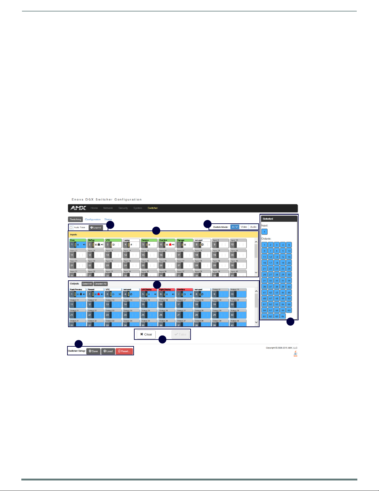
67
NX-Series Controllers - WebConsole & Programming Guide
WebConsole - Switching Options
A
D
B
E
F
C
G
Switching Overview
The Switching page is used to route the system’s inputs to its outputs during system setup. Each input and output can be labeled
by filling in the Input Name or Ou tput Name field on the Conf iguration page. The one exception to this statement is the audio input
“Downmix” button, which cannot be renamed.
NOTE: The number of available video and audio inputs and outputs depends on the Enova DGX 100 Series model and the number and
type of boards it contains.
Color-coded Switch Selection and Switching Orientation
Yellow buttons indicate they have been selected but not switched; blue buttons indicate an already routed switch.
TIP: When disconnecting switches, selecting an input or an output in an already routed switch will turn the button from blue to white,
but will leave a thin blue line around the button to indicate it is still active until Take is pressed.
From a cleared state, switching is accomplished from either an input-orientation or an output-orientation depending on whether an
input or an ou tput is selected first. When an input is selected first, the Inputs title bar turns yellow (see FIG. 57) and
“input-orientation switching” is enabled. Multiple outputs can then be selected for the input followed by Take to execute the
switch(es). When an output is selected first, the Outputs title bar turns yellow and “output-orientation switching” is enabled. A
single input can then be selected for the output followed by Take to execute the switch.
Pressing Clear before pressing Take allows you to start over.
NOTE: The default selection (input button highlighted blue) for the Switching pane is Input 1, which also appears in the Input section
of the vertical “Selected” bar to the right. All output buttons that the default selection is routed to are highlighted and also appear in
the Outputs section of the Selected bar. FIG. 57 shows the factory default switch of one-to-all.
WebConsole - Switching Options
FIG. 57
Switching page allows routing of inputs to outputs during system setup
Page 68

WebConsole - Switching Options
68
NX-Series Controllers - WebConsole & Programming Guide
A
Title bar
Board state icons
B
C
D
E
F
G
Switching Page Components
The Switching page features the following components (labeled alphabetically to correspond to FIG. 57 on previous page):
Auto Take button (default is unselected) – when checked, this button persists the Auto Take function and remains illuminated until
unchecked. O nce an input or out put is selected, a click on an output for the inpu t or on an input fo r an o utput will execute a switch.
This allows for quick cycling through several inputs for a selected output. Note that when a bu tton is selected, it also appears in the
Configuration page with signal details (for button/signal details, click the Legend button).
Legend button – click to open an additional browser tab (Audio/Video Legend) which displays the legend key with details regarding
the state of the input (source) and output (destination) connections. The browser tab opens in a tearaway tab/window that can be
dragged and dropped as a standalone desktop window for side-by-side reference with the Switcher/Configuration pages.
NOTE: The label on the title bar can be edited in the Input or Output Name field on the Configuration page.
NOTE: If the enclosure does not include a full set of input/output boards, input and output buttons for connectors that are not
available display with a gray Title bar (i.e., No Card).
Switch Mode buttons – click the A/V (default), Video, or Audio button to select the type of signal to be switched. These buttons
correspond to the available video and audio Virtual Matrices (VMs) in the system. For additional information on the Switch Mode,
see page 69.
Inputs section – this section contains buttons for each of the available input signals (per selected Switch Mode) in the system.
Click the input button that needs to be switched. Scroll bars on the right-hand side provide access to any inputs on large systems
which are not currently visible.
Downmix button – the Audio Switch Mode must be selected before the Downmix button displays. The input source used for the
downmix signal is selected on the Configuration page.
Outputs section – this section contains buttons for each of the available output signals in the system. Click the output button(s)
that needs to receive the signal from the currently selected inpu t bu tton. Note that when the c urrently selected button is an output,
it also appears in the Configuration page with signal details (for button/signal details, click the Legend button). Scroll bars on the
right-hand side provide access to any outputs on large systems which are not currently visible.
Select All and Deselect All buttons – these buttons appear only after an input is selected. Click as necessary to select or deselect all
output bu ttons.
Clear button – click to deselect all inputs and outputs (if selected, the Auto Take button state persists) and clear routing status in
the Configuration pane. No te that the Clear button does not disconnect switches. After the Clear button is selected and the input or
one of the ou tputs already routed is selected, the buttons turn blue to indicate current status. Selecting an output will show status
for the input routed to it, not the o ther outputs also routed from the same input.
Ta ke button – click to execute the switch for the selected input and output(s). After the switch is made, the current content in the
Switching and Configuration pages persists until further action is taken. Note that the Take button is grayed out until one input and
one or more outputs have been selected for routing; once these conditions are met, the Take button becomes active. After the Take
button is clicked, all of the buttons clear their status.
Selected status bar (non-editable) – this status bar provides quick visual confirmation of input and output selections and their
status (blue = currently routed; yellow = ready to route, waiting further action; blue outline = currently routed, but deselected in
preparation to disconnect).
Switcher Setup button options are available on both the Switching page and the Conf iguration page.
Save and Load buttons – after a system has been set up per the installation’s requirements, the configuration values for the entire
switcher’s state (i.e., currently routed switches, video settings, and audio settings) can be saved and reloaded onto another
system(s) or backup system(s) for reu se. The f ile type is .xdg with XML content. When the Save bu tton is clicked, the f ile is saved as
a managed content (non-editable text) file.
Page 69

WebConsole - Switching Options
69
NX-Series Controllers - WebConsole & Programming Guide
Group Restore to Default button – click to open the Warning dialog box below, which requires you to select an A/V Group and an
I/O Group to restore to their factory default settings.
Switch Mode
The Switch Mo de buttons allow you to cho ose between switching Au dio fo llow Vi deo (A/V), Video (with embedded au dio), or Audio
only.
IMPORTANT: Support for the Audio Switch Mode (VM 2) requires Audio Switching Boards in the enclosure.
A/V and Video input and output ranges cover the basic switching size of the system:
8x8, 16x16, 32x32, or 64x64
Audio only input and output ranges cover the embedded audio as part of the basic switching size of the system, plus the
audio available on the Audio Switching Boards (ASB) in the expansion slots, plus the assignment of one input as a
downmixed audio c hannel:
Enova DGX 800: 1-8 embedded au dio, 9-16 audio only, 17 downmix audio o nl y
Enova DGX 1600: 1-16 embedded audio, 17-24 audio only, 25 downmix audio only
Enova DGX 3200: 1-32 embedded audio, 33-40 audio only, 41 downmix audio only
Enova DGX 6400: 1-64 embedded au dio, 65-80 audio only, 81 downmix audio only
To e xe c ut e a switch, click the Switch Mode button (otherwise the switch will default to A/V), an Input button, an Output button(s),
and the Take button. (This is called input-oriented switching, also known as one-to-many switching.)
NOTE: If you select an output button first (output-oriented switching, which can only be one-to-one switching), you must
input button next followed by the Take button, i.e., you cannot select additional outputs before you select the input. If you select an
output button first and then the input button, the only way to select multiple outputs is to click the Clear button and click the input
button followed by the output buttons.
To de se lec t (clear status) of an input button that has already been selected, click another input button or click Clear.
To de se lec t (clear status) of a single output button that has already been selected (before an input button), click another ou tpu t
button or Click Clear.
To clear s t at u s of an input and any or all output buttons, click Clear.
To di s c on n e ct all currently selected outputs for an input, click the Deselect All button followed by clicking Take.
To exe c u te a switch with a downmixed signal,* the Audio Switch Mode must be selected and the inpu t used for the Downmix signal
must be selected on the Configuration page. Click the Downmix button, click the output(s), and click Take.
* Audio Switching Boards must be present for this functionality to work.
select an
Page 70

WebConsole - Switching Options
70
NX-Series Controllers - WebConsole & Programming Guide
Switch Mode must be set to Audio
Drop-down list displays
inputs available for
downmixing
Downmix Source
routes the selected
input (Input 1 in the
example)
Downmix Input button
Conf iguring/Switching the Downmix Signal
When the system contains Audio Switching Boards, one embedded audio signal** can be downmixed and routed at any given time.
** Signal must be Dolby, TrueHD, Dolby Digital, DTS-HD Master Audio, DTS, or 2 CH through 8 CH L-PCM.
When Audio Switch Mode is selected, the “Downmix” input automatically displays as the last analog audio input+1. The Downmix
Input number for each of the Enova 100 Series models is shown in the following table.
Downmix Input #
Enova DGX 800 17
Enova DGX 1600 25
Enova DGX 3200 41
Enova DGX 6400 81
NOTE: The table above also applies to Enova 8/16/32/64 enclosures that have been upgraded with an Enova DGX 100 Series CPU
and that contain Audio Switching Boards.
From the Configuration page – to designate which source will be routed on the Downmix Input, click the Downmix button in the
Switching pane on the left and then select the input from the Downmix Source drop-down list in the Configuration pane on the
right.
FIG. 58 Downmix inpu t ready to switch or conf igure
Designating an Input for Downmixing (from Conf iguration page)
1. In the Switching pane on the left, select Audio Switch Mode.
The Downmix button displays at the end of the input buttons.
2. Select the Downmix button.
3. In the Conf iguration pane on the right, select the input from the Downmix Source drop-down list.
The Downmix signal is ready to apply any of the configuration options or to execute switches.
4. To use a different input source for downmixing, repeat Steps 1-3 (only one input can be downmixed at a time).
Page 71

WebConsole - Switching Options
71
NX-Series Controllers - WebConsole & Programming Guide
A
C
B
F
D
E
G
A
B
C
Video button
Audio button
Conf iguration Page
The Configuration page is used to configure inputs and outputs in the system. The most recently selected input or output displays
in the Configuration page in accordance with the currently selected Config Viewer button (Recent, Inputs Only, or Outputs Only).
The Configuration page displays the Switching page components compressed on the left. Note that the components are active, i.e.,
they can be used for all switching functionality without needing to return to the full Switching page.
FIG. 59
Configuration page allows conf iguration of inputs and outputs
Conf iguration Components
Any changes made in the Configuration page occur instantaneously on the attached devices. In addition, when you select an input
or an output on the left, the options on the right side of the page change to reflect the current settings. Configuration is not
affected by power loss, restarting the enclosure, or upgrading the firmware.
NOTE: The number of available video and audio inputs and outputs depends on the Enova DGX 100 Series model and the number and
type of boards it contains.
Switching page components – all of the components from the Switching page are compressed and displayed (for details, see
previous section on the “Switching Page”).
Input and Output buttons are selected individually for configuration.
Input # or Output # Conf iguration heading (large text above the Video and Audio tabs) – changes according to the input or outpu t
currently selected for conf iguration.
Video (default) and Audio tabbed views – click tabs to configure the video or audio signal that is selected in the Switching view. The
signal will be either input or output depending on the Config Viewer button selection. The setting options vary depending on the
signal.
Conf ig Viewer buttons – the Recent, Inputs Only, and Outputs Only buttons allow you to choose the source or destination signal to
be configured. Settings for the current Config Viewer remain when leaving the page and reactivate upon return. When the Recent
button is clicked, the last selected input or output and its settings display. If no inputs or outputs are selected before opening the
page, then the information will be cleared.
NOTE: When the Inputs Only button is selected, clicking an output button in the Switching components will result in blank
Configuration information; the same is true for selecting the Outputs Only button and then clicking an input button.
Selecting any video or au dio signal bu tton will dis pla y corres po nding informat io n as fol lows:
Input or Outpu t button – an enlargement of the button selected under Switching (or from the Switching page) appears on the
Configuration side with the source name and number, plus signal details (for an explanation of the button’s details, click the Legend
button).
Input Name or Output Name f ield – use to label the buttons in the Switching pane (and on the Switching page).
Type the name in the field and press Enter on the keyboard.
Page 72

WebConsole - Switching Options
72
NX-Series Controllers - WebConsole & Programming Guide
DEF
G
Restore to Default (red ) button – click to open the Warning dialog box below, which requires you to select the Yes button to restore
the currently selected input or output to its factory default settings.
Video Details or Audio Details button – click to display additional video or audio details for inpu ts or outputs, depending on current
selection (video: colorSpace, flags, pixelclock, etc.; audio: CTS Value, N Value, Audio Mute State, etc.). Examples of both Video Input
and Output Details are shown below. Audio details are similar.
Video, DXLink, and Audio settings – the settings section of the Configuration page changes depending on the type of signal,
whether it is an input or an output, and whether a DXLink unit is attached. A variety o f interface controls are used to change the
settings (e.g., buttons, sliders, drop-down lists) depending on the values involved. Details for these settings follow this section.
Switcher Setup button options are available on both the Switching and the Configuration pages.
Save and Load buttons – after a system has been set up per the installation’s requirements, the configuration values for the entire
switcher’s state (i.e., currently routed switches, video settings, and audio settings) can be saved and reloaded onto another
system(s) or backup system(s) for reu se. The f ile type is .xdg with XML content. When the Save bu tton is clicked, the f ile is saved as
a non-editable text file.
Group Restore to Default button – click to open the Warning dialog box below, which requires you to select an A/V Group and an
I/O Group to restore to their factory default settings.
IMPORTANT: When selecting a signal to conf igure, the Config Viewer button selection, Inputs Only or Outputs Only, must
to the input or output button selected.
correspond
Page 73

WebConsole - Switching Options
73
NX-Series Controllers - WebConsole & Programming Guide
Video Settings
Video settings display when the Switch Mode is A/V or Video, the Video tabbed view is selected, and a specific inpu t or output is
selected.
Inputs Only
Ge n e r a l :
Resolutio n – displays Resolution (read-only).
EDID Mode – in the drop-down list, select the resolution type (All Resolutions, Wide-Screen, Full-Screen, or Custom).
Preferred EDID – in the d ro p-down list, select t he specif ic resolution/refresh rate.
Save EDID button – use to save (persist them in memory) the EDID settings for the currently selected input
Load EDID button – use to load the EDID settings for the currently selected input to other inputs.
HDCP Setting:
HDCP Compliance – if desired, click the check box to enable HDCP compliance.
NOTE: When EDID Mode/All Resolutions is selected, the Preferred EDID drop-down list includes both standard EDIDs and Video
Information Code (VIC) EDIDs (denoted by either a “p” or an “i”). For a complete list of VIC EDIDs for your input boards see the “EDID
Resolutions Supported through Local DDC” section of the applicable board chapter.
Outputs Only
Ge n e r a l :
Scaling (Mode) – click the button for the mode (Auto, Manual, or Bypass)
Resolution – in the drop-down list, select the resolution/refresh rate; select the “Show only EDID Display Supported
(DS)” check box if desired.
Aspect Ratio – click either Maintain or Stretch (Zoom and Anamorphic are also available for DXLink outputs).
Save EDID – click this button to save the EDID setting for the currently selected output.
Page 74

WebConsole - Switching Options
74
NX-Series Controllers - WebConsole & Programming Guide
Display Settings:
Video Mute – click the check box to mute the video.
Video Freeze – click the check box to freeze the video.
Test Patte rn – in the drop-down list, select Off, Color Bar, Gray Ramp, SMPTE Bar, HiLo Trak, Pluge, or X-Hatch.
Blank Color – in the drop-down list, s elect Black or Blu e.
Screen Sleep – click the check box to place the display in sleep mode; in the Sleep Delay (ms) box, set the delay time in
milliseconds.
On-Screen Display:
Enable OSD – click check box to enable.
OSD Color – in the drop-down list, select Black, Blue, White, or Yellow.
OSD Position – in the drop-down list, select Top Left, Top Right, Bottom Left, or Bottom Right.
Image Adjustments:
Brightness – use the slider bar to adjust (range: 0 to 100).
Contrast – use the slider bar to adjust (range: 0 to 100).
NOTE: For additional EDID configuration information, see page 79.
Page 75

WebConsole - Switching Options
75
NX-Series Controllers - WebConsole & Programming Guide
TX Settings:
DXLink Quality – green = good; red = poor; number
indi cates deg ree or lack of quality
Firmware Version – current version
Friendly Name – current name
IP Address – for auto-setup, displays integrated
Master’s IP address
Subnet Mask – current setting
D. P. S. – current setting
MAC Address – current setting
Auto-Setup – Status (Enable/Disable) and Force to
Auto-setup button
DIP Settings – indicates settings on DIP switch
Reboot button – reboots TX
Refresh button – updates status of TX settings
RX Settings:
DXLink Quality – green = good; red = poor; number
indicates deg ree or lack of quality
Firmware Version – current version
Friendly Name – current name
IP Address – for auto-setup, displays integrated
Master’s IP address
Subnet Mask – current setting
D. P. S. – current setting
MAC Address – current setting
Auto-Setup – Status (Enable/Disable) and Force to
Auto-setup button
DIP Settings – indicates settings on DIP switch
Reboot button – reboots RX
Refresh bu tton – updates status o f RX settings
DXLink Video Settings
DXLink specific video settings display when a DXLink Twisted Pair or DXLink Fiber Transmitter or Receiver (or other DXLink
equipment) is connected to the selected input or output. These settings display in addition to the normal video settings for the
input or output described in the previous section. The Video tabbed view must be selected.
DXLink (Twisted Pair or Fiber) Transmitters (for selected video input)
Video Priority – click either the HDMI, Analog, or Manual button.
AV Source – click Analog or Digital.
Video Type – non-editable.
DXLink Details bu tton – click to display additional settings for the DXLink Transmitter.
VGA Settings (DXLink Twisted Pair only) – use sliders to adjust Phase, Horizontal Shift, and Vertical Shift settings.
IMPORTANT: The DXLink settings are not
opens when the DXLink Details button is clicked must be
asynchronous. To obtain the latest information, the Refresh button in the dialog box that
clicked.
DXLink (Twisted Pair or Fiber) Receivers (for selected video output)
DXLink Details bu tton – click to display additional settings for the DXLink Receiver.
Page 76

WebConsole - Switching Options
76
NX-Series Controllers - WebConsole & Programming Guide
Audio Settings
Audio settings display when the Switch Mo de is A /V or Au dio (for details, see page 6 9), the Au dio tabb ed view is selected, an d a
specific inpu t or output is selected. The audio settings can be used to conf igure any digital signal processing required for the audio
signal that is selected in the Switching view.
Inputs Only
Ge n e r a l :
Stereo or Mono buttons – click either.*
Input Gain (dB) – use the slider bar to adjust (-24 dB to +24 dB),
Encoding – PCM (read only)
EDID Mode – from the drop-down list, select the mode (Basic, PCM 2-Channel, PCM Multi-Channel, Dolby Digital,
Dolby Digital + DTS, Dolby Digital + MPEG, Dolby Digital + AAC, Dolby TrueHD, or DTS HD Master).
Compression:
Buttons at top – click Off, Low, Medium, High, or Custom.
Threshold – use the slider bar to adjust (range: 0 to -60).
Attack (ms), Release (ms), and Ratio – adjust the values in the boxes (either enter values or use the arrows)
NOTE: When in Low, Medium, or High, changes to any of the other Compression settings will automatically change the Compressor
mode to Custom.
* Setting this option to “Mono” audio on the input results in the left channel being sent to both the left and right output channels.
Page 77

WebConsole - Switching Options
77
NX-Series Controllers - WebConsole & Programming Guide
Outputs Only
Ge n e r a l s et t i n g s :
Encoding – PCM (read only).
Output Format – click Stereo or Mono.*
Test Tone Enable – click Disable or Enable.
Test Tone Generator – from the drop-down list, select Off, 60Hz, 250Hz, 400Hz, 1kHz, 3kHz, 5kHz, 10kHz, Pink Noise, or
White Noise.
Audio Routing – cli ck Embedded o r Switched.* *
* Setting this option to “Mono” audio on the output results in the left and right channels being combined and sent to both the left
and right output channels equally.
** W ith Audio Switchi ng Bo ards in the system, Au dio Rou ting defaults to Switched.
Levels & Delay:
Mute – click Mute if desired.***
Output Volume (0 to 100)
Min/Max (0 to 100)
Balance (-20 to 20, left to right)
Sync Delay (ms) (0 to 200).
*** Changing the volume level will not un-mute the signal; however, the new volume level is saved and when the Mute button is
deselected, the volume returns at the new level.
10-Band Parametric Equalizer:
Enabled – this check box must be selected before the Equalizer optio ns are available .*
Tone Adjust – use the drop-down box to select: Off, Voice, Music, or Movie (Tone Adjust is applied on top of any
equalizer adjustments).
Reset EQ – click this button to reset the all of the Equalizer values.
Page 78

WebConsole - Switching Options
78
NX-Series Controllers - WebConsole & Programming Guide
Bell = 0.1 to 20
Band Pass = 0.1 to 20
Band Stop = 0.1 to 20
High Pass = 0.5 to 1.4
Low Pass = 0.5 to 1.4
Tre b l e S h e l f = 0 . 5 to 1
Bass Shelf = 0.5 to 1
TX Settings:
DXLink Quality – green = good; red = poor; number
indi cates deg ree or lack of quali ty
Firmware Version – current version
Friendly Name – current name
IP Address – for auto-setup, displays integrated
Master’s IP address
Subnet Mask – current setting
D. P. S. – current setting
MAC Address – current setting
Auto-Setup – Status (Enable/Disable) and Force
to Auto-setup bu tton
DIP Settings – indicates settings on DIP switch
Reboot button – reboo ts TX
Refresh button – updates status of TX settings
Blue Handles – u se the sliders (blue handles) to adjust Equalizer valu es.
The fo llowing d ro p-down lists ca n also be u sed to adju st Equalizer values.
Band – numbered from 1 to 10.
Filter – the options are Bell, Band Pass, Band Stop, High Pass, Low Pass, Treble Shelf, and Bass Shelf.
Frequency – the adjustment range is from 20 to 20000 (Hz).
Gain – the adjustment range is from -12 to 12.
Q – the adjustment range depends on the filter selected:
* On reboot, the Enabled box always returns to the checked (default) state. To disable the Equalizer options over a reboot, set the
“y” (vertical) vertex to 0 (zero).
DXLink Audio Settings
DXLink specific audio settings display when a DXLink Twisted Pair or DXLink Fiber Transmitter or Receiver (or other DXLink
equipment) is connected to the selected input or ou tput. These settings display in addition to the normal audio settings for the
input or output described in the previous section. The Audio tabbed view must be selected.
DXLink (Twisted Pair or Fiber) Transmitter (for selected audio input)
Audio Priority – click either the Auto or Manual button.
Audio Source – click either the HDMI, SPDIF, or Analog button
DXLink Details bu tton – click to display additional settings for the DXLink Transmitter.
Page 79

WebConsole - Switching Options
79
NX-Series Controllers - WebConsole & Programming Guide
RX Settings:
DXLink Quality – green = good; red = poor; number
indicates deg ree or lack of qu ality
Firmware Version – current version
Friendly Name – current name
IP Address – for auto-setup, displays integrated
Master’s IP address
Subnet Mask – current setting
D. P. S. – current setting
MAC Address – current setting
Auto-Setup – Status (Enable/Disable) and Force to
Auto-Setup button
DIP Settings – indicates settings on DIP switch
Reboot button – reboo ts RX
Refresh button – updates status of RX settings
DXLink (Twisted Pair or Fiber) Receivers (for selected audio output)
Active Output – click either the HDMI, Analog, or All button.
DXLink Details bu tton – click to display additional settings for the DXLink Receiver.
EDID Conf iguration
NOTE: Because signals routed through HDMI, DVI, DXLink Twisted Pair, and DXLink Fiber Boards in an Enova DGX 100 Series Switcher
normally produce a quality image, you will not need the information in this section unless the installation has special EDID
requirements.
A default EDID (Extended Display Identification Data) is stored on the boards. This data is provided by the display and presented to
the video source and includes timing and display size/format information for best performance.
Setting an EDID for an Input:
1. From Configuration page / Switch Mode (on the left), click the Video button.
2. Check to be sure the Conf ig Viewer on the top right is set to Inputs Only.
3. From the Switching pane on the left, select the video input.
4. Under General settings f rom the EDID Mode d ro p-down list, select the mo de (All Resolutio ns, Wide-Screen, Full-Screen, o r
Custom).
5. Select th e Preferred EDID from the d rop-down list o f resolutions/refresh rates.
6. Click the Save EDID button.*
* Once the preferred EDID is saved, it can be loaded to another input(s).
Setting an EDID for an Output:
1. From Configuration page / Switch Mode (on the left), click the Video button.
2. Check to be sure the Conf ig Viewer on the top right is set to Outputs Only.
3. From the Switching pane on the left, select the video output.
4. Under General settings from the Resolutio n drop-down li st, select the res olution/refresh rate.**
5. Under General settings, click the Save EDID bu tton.
** Click the “Show only EDID Display Supported (DS)” check box to narrow the drop-down list to show only those resolution/
refresh rate options marked DS (Display Supported).
Setting the EDID Mode for an Audio Input:
1. From Configuration page / Switch Mode (on the left), click the Audio button.
2. Check to be sure the Conf ig Viewer on the top right is set to Inputs Only.
3. From the Switching page components on the left, select the audio input.
4. Under General settings from the EDID Mode drop-down list, select the mode: Basic, PCM 2-Channel, PCM Multi-Channel,
Dolby Digital, Dolby Digital + DTS, Dolby Digital + MPEG, Dolby Digital + AAC, Dolby TrueHD, or DTS HD Master.
Loading and Saving EDIDs
For custom EDIDs, click the Load EDID button and browse for the .edid f ile on your device/computer. Once the EDID is loaded, make
any necessary changes and use the Save EDID button to save the altered .edid file to your device/compu ter.
NOTE: Some devices run on a secured file-system. As such, file-system operations (e.g., Load and Save operations) may not be
supported by the device’s default capabilities and may require downloading a file manager application.
Page 80

WebConsole - Switching Options
80
NX-Series Controllers - WebConsole & Programming Guide
E
D
C
B
A
F
G
Status Page
The Status page is used to check a number of the switcher’s components and their states. The components (from top to bottom of
page) display status for Alarms, the Chassis, the Master CPU Board, Input and Output Boards, and Input and Output Expansion
Audio Boards. A quick glance at this page will indicate whether the system is running okay (green text will state OK) or if any thing
is failing (red text will state FAIL.)
IMPORTANT: The Status page settings are not
The example provided in the figure below is based on an Enova DGX 3200 Switcher with two each standard Input and Output
Boards, as well as two Expansion Audio Boards.
asynchronous. To obtain the latest information, the Refresh button must be clicked.
FIG. 60
Status page indicates status of system components
Page 81

WebConsole - Switching Options
81
NX-Series Controllers - WebConsole & Programming Guide
A
B
CDE
F
G
System Auto-Setup check box – select to place the system in auto-setup mode (i.e., the mode wherein the system requires only a
single IP address for the integrated Master, and each endpoint is automatically configured for communication via a private LAN
hosted by the integrated Master).
The following must be adhered to when using auto-setup mode (default):
Endpoints must be set to DHCP Mode (default)
Endpoints must use NDP Master connection mode (default)
Endpoints must not be currently bound (traditional NetLinx binding) to a Master
Endpoints DIP switch setting for Toggle #3 (network connectivity) is ignored while in auto-setup mode
NOTE: Some devices run on a secured file-system. As such, file-system operations (e.g., Load and Save operations) may not be
supported by the device’s default capabilities and may require downloading a file manager application.
Alarms – if any are red, consult the individual Fan, Power, and Temperature co mponents on the page to help pinpoint the location of
the problem.
Refresh button – if necessary, use the Refresh button to view system status changes.
Chassis field – this field contains readouts for individual fan speeds, individual power supply status, and the current temperature of
the chassis (shown in degrees Celsius). Each readout displays in a color to convey statuses of OK, Fail, or no problems detected
(black). Fan speed information is displayed by individual fans (Fan #) and the fan assembly where each fan is located (FAN ASM #).
Power supply and temperature information is available in each switcher’s General Specifications table in the “Product Overview and
General Specifications” chapter.
Master CPU (MCPU) Board f ield – this field displays information for Status, Model number of the integrated Master, FG (part)
number, Version, Temperature (actual degrees in Celsius with OK or FAIL status), and Power (OK or FAIL status).
Input and Output Board f ields – these fields give detailed information for each input or output board in the enclosure: Slot, Status,
Type, FG (part) number, Version, Temperature (actual degrees in Celsius with OK or FAIL status), and Power (OK or FAIL status). A
red Reboot button at the right cycles power to the individual board.
Input and Output Audio Expansion Boards f ields – these fields give detailed information for each expansion input or output board
in the enclosure: Slot, Status, Type, FG (part) number, Version, Temperature (actual degrees in Celsius with OK or FAIL status), and
Power (OK or FAIL status). A red Reboot button at the right cycles power to the individual board.
Switcher Setup (Save, Load, and Group Restore to Default) buttons – after a system has been set up per the installation’s
requirements, the configuration can be saved and reloaded onto another system(s) or backup system(s) for reuse. The Group
Restore to Default button returns the system to its last previously saved state. This button will restore control values to default
(initial) values. (This Restore button performs the same function for the entire system as the Configuration page’s Restore to
Default bu tton does for in dividual inpu ts or outputs.)
Refresh button – if necessary, use the Refresh button to view system status changes.
System Configuration Interface Tips
To change the network connection type from DHCP (default) to Static IP – navigate to Network/IPv4; click on Specific IP
Address; enter values into the IP Address, Subnet Mask, and Gateway f ields; then click Accept.
To enable/disable auto-setup ¡V navigate to Switcher/Status; click the System Auto-Setup check box to add a check mark
(enabled) or remove a check mark (disabled).
To route audio without the benefit of audio options available via the interface – navigate to Switcher/Configuration; select
Audio Switch Mode; select Outputs Only in the Config Viewer options; select the desired output; select Switched Audio
Routing from the General options.
Page 82

82
NX-Series Controllers - WebConsole & Programming Guide
NetLinx Programming
Overview
This section describes the Send_Commands, Send_Strings, and Channel commands you can use to program the Master. The
examples in this section require a declaration in the DEFINE_DEVICE section of your program to work correctly.
Refer to the NetLinx Programming Language instruction manual for specif ics about declarations and DEFINE_DEVICE information.
NOTE: All f ile names on the X-Series controllers are case sensitive. This includes all user files created or used within NetLinx or Java
code. If you have legacy code that uses files, it is important that you verify that every reference to each file is consistent with regard
to case. If your legacy code generates an error when accessing a f ile, it is likely due to inconsistent use of case in the f ilename.
Port Assignments by NetLinx Master
The following table lists the port assignments for NetLinx Masters:
Port Assignments By Master
Master RS-232 RS-232/422/485 IR/Serial IR/RX Relays I/O PoE
NX-1200 Port 2 Port 1 Ports 11-12 Port 20 N/A Port 22 N/A
NX-2200 Ports 2-4 Port 1 Ports 11-14 N/A Port 21 Port 22 N/A
NX-3200 Ports 2-4, 6-8 Ports 1, 5 Ports 11-18 N/A Port 21 Port 22 N/A
NX-4200 Ports 2-4, 6-8 Ports 1, 5 Ports 11-18 N/A Port 21 Port 22 Ports 24-27
Port Assignments by All-in-One-Presentation Switcher
The following table lists the port assignments for Enova All-in-One Presentation Switchers:
Port Assignments By Enova All-in-One Presentation Switcher
Master RS-232 RS-232/422/485 IR/Serial Relays I/O
DVX-22xxHD Ports 2-4 Port 1 Ports 11-14 Port 21 Port 22
DVX-325xHD Ports 2-4, 6-8 Ports 1, 5 Ports 11-18 Port 21 Port 22
NetLinx Programming
Port Assignments by Massio ControlPad
The following table lists the port assignments for Massio ControlPads:
Port Assignments By ControlPad
ControlPad RS-232 IR/Serial Relays I/O NetLinx
MCP-106 Port 1 Port 11 N/A N/A Port 28
MCP-108 Ports 1-2 Ports 11-12 Port 21 Port 22 Port 28
Page 83

NetLinx Programming
83
NX-Series Controllers - WebConsole & Programming Guide
Serial, IR, AxLink, and PoE Port Diagnostics
When a string is sent to a serial port or an IR pulse to an IR port, the X-Series controllers can detect and report if the port being
used is in a fault condition. The controllers can also detect certain fault conditions on the AxLink bus. The following fault conditions
are recognized:
The serial cable is not connected
The Serial pin is connected to another pin
The IR emitter is no t connected
The IR emitter is wired backwards
One or both AxLink bus data pins are shorted to power or ground
The maximum power for all PoE ports (72W) has been exceeded or the power supply voltage is outside of the
recommended limits
The maximum current for a single PoE port has been exceeded or the load has disconnected from an individual port
On the first attempt to use a port that is in a fault condition, the controller will do the following:
Quickly flash the front panel LED of the port being used 10 times
Generate an ONERROR data event in NetLinx
Report the error to any Duet Module that has claimed the port
Report the error to RMS if the controller is connected to an RMS server
Set an error flag for that port
The status of the error flag can be queried using the GET FAULT NetLinx command, which will result in a DATA EVENT where the
return status can be parsed.
NOTE: If the fault condition persists, subsequent attempts to use the same port will only result in the quick flashing of the front panel
LED. The ONERROR event and the reporting to a Duet Module or RMS only occur on the first attempt after booting or after the fault
status is cleared. This prevents a flood of redundant error messages when a faulted port is used continuously.
The fault status is cleared on a successful transmission over the port, and also can be cleared manually using the CLEAR FAULT
NetLinx command.
For serial and IR ports, an error condition is only checked at the time the port is used, so unused serial and IR ports will not
generate errors. AxLink bus errors are checked at boot time.
Page 84

NetLinx Programming
84
NX-Series Controllers - WebConsole & Programming Guide
Master SEND_COMMANDs
These commands are specific to the Master and not the Controller. These commands are sent to the DPS 0:1:0 (the Master you are
connected to).
A device (<DEV>) must first be defined in the NetLinx programming language with values for the Device: Port: System (<D:P:S>).
Master SEND_COMMANDs
Command Description
CLOCK Set the date and time on the Master. The date and time settings are propagated over the local bus.
Syntax:
SEND_COMMAND <DEV>,"'CLOCK <mm-dd-yyyy> <hh:mm:ss>'"
Variables:
mm-dd-yyyy = Month, day, and year. Month and day have 2 significant digits. Year has 4 significant digits.
hh-mm-ss = Hour, minute, and seconds. Each using only 2 significant digits.
Example:
SEND_COMMAND 0,"'CLOCK 04-12-2005 09:45:31'"
Sets the Master's date to April 12, 2005 with a time of 9:45 am.
G4WC Add G4 Web Control devices to Web control list displayed by the Web server in a browser. The internal G4WC
~IGNOREEXTERNAL CLOCKCOMMANDS
Send command (to Master 0:1:0) has been revised to add G4 Web Control devices to Web control list displayed
in the browser.
Syntax:
SEND_COMMAND <D:P:S>,"'G4WC "Name/Description",IP Address/URL,IP Port,Enabled'"
Variables:
• Name/Description = A string, enclosed in double quotes, that is the description of the G4 Web Control
instance. It is displayed in the browser.
• IP Address/URL = A string containing the IP Address of the G4 Web Control server, or a URL to the G4 Web
Control server.
• IP Port = A string containing the IP Port of the G4 Web Control Server.
• Enabled = 1 or 0. If it is a 1 then the link is displayed. If it is a 0 then the link is disabled.
The combination of Name/Description, IP Address/URL, and IP Port are used to determine each unique
listing.
Example:
SEND_COMMAND 0:1:0,"'G4WC "Bedroom",192.168.1.2,5900,1'"
Adds the BEDROOM control device using the IP Address of 192.168.1.2.
Set the Master so that it cannot have it’s time set by another device which generates a ‘CLOCK’ command.
Syntax:
SEND_COMMAND <D:P:S>,"'~IGNOREEXTERNALCLOCKCOMMANDS'"
Example:
SEND_COMMAND 0:1:0,"'~IGNOREEXTERNALCLOCKCOMMANDS'"
Page 85

NetLinx Programming
85
NX-Series Controllers - WebConsole & Programming Guide
Master IP Local Port SEND_COMMANDs
These commands are specific to the Master and not the Controller. These commands are sent to the DPS 0:1:0 (the Master). A
device must first be defined in the NetLinx programming language with values for the Device: Port: System.
In these programming examples, <DEV> = Device. The term <D:P:S> = Device:Port:System.
Master IP Local Port SEND_COMMANDs
Command Description
UDPSENDTO Set the IP and port number of the UDP local ports destination for sending future packets. This is only available for Type 2
and Type 3 Local Ports. Type 2 and Type 3 are referring to the protocol type that is part o f the IP_CLIENT_OPEN call (4th
parameter).
Typ e 1 is TCP.
Type 2 is UDP (standard)
Typ e 3 is U D P (2 wa y)
The NetLinx.axi defines constants for the protocol types:
CHAR IP_TCP = 1
CHAR IP_UDP = 2
CHAR IP_UDP_2WAY = 3
Syntax:
SEND_COMMAND <D:P:S>,"'UDPSENDTO-<IP or URL>:<UDP Port Number>'"
Variables:
• IP or URL = A string containing the IP Address or URL of the desired destination.
• UDP Port Number = A String containing the UDP port number of the desired destination.
Example 1:
SEND_COMMAND 0:3:0,"'UDPSENDTO-192.168.0.1:10000'"
Any subsequent SEND_STRING to 0:3:0 are sent to the IP Address 192.168.0.1 port 10000.
Example 2:
SEND_COMMAND 0:3:0,"'UDPSENDTO-myUrl.com:15000'"
Any subsequent SEND_STRING to 0:3:0 are sent to the URL myURL.com port 15000.
Page 86

86
NX-Series Controllers - WebConsole & Programming Guide
SSH SEND_COMMANDs
These command open or close SSH communication with a server:
SSH SEND_COMMANDs
SSH_CLIENT_CLOSE Closes an open SSH communication port with a server.
Syntax:
SEND_COMMAND <DEV>,"'SSH_CLIENT_CLOSE(LocalPort)'
Parameters:
• LocalPort - A user-defined (non-zero) integer value representing the local port on the client machine to use for
this conversation. This local port number must be passed to SSH_CLIENT_OPEN to open the conversation.
Returns:
This function always returns 0. Errors are returned via the DATA_EVENT ONERROR method. The following errors
may be returned from the call:
2 - General failure (out of memory)
4 - Unknown host
6 - Connection refused
7 - Connection timed out
8 - Unknown connection error
9 - Already closed
14 - Local port already used
16 - Too many open sockets
Example:
SEND_COMMAND <DEV>,"'SSH_CLIENT_CLOSE(5000)'"
SSH_CLIENT_OPEN Opens a port for SSH communication with a server.
Syntax:
SEND_COMMAND <DEV>,"'SSH_CLIENT_OPEN(LocalPort, ServerAddress, remotePort, username,
password, privateKeyPathname, privateKeyPassphrase)'"
Parameters:
• LocalPort- A user-defined (non-zero) integer value representing the local port on the client machine to use for
this conversation. This local port number must be passed to SSH_CLIENT_CLOSE to close the conversation.
• ServerAddress - A string containing either the IP address (in dotted-quad-notation) or the domain name of the
server to which you want to connect.
• remotePort - The port number on the server that identifies the program or service that the client is requesting,
typically 22
• username - Login user name
• password - Password for the user name, null if using PKI
• privateKeyPathname - Path to private key
• privateKeyPassphrase - Password for private key.
Returns:
This function always returns 0. Errors are returned via the DATA_EVENT ONERROR method. The following errors
may be returned from the call:
2 - General failure (out of memory)
4 - Unknown host
6 - Connection refused
7 - Connection timed out
8 - Unknown connection error
9 - Already closed
14 - Local port already used
16 - Too many open sockets
Example:
SEND_COMMAND <DEV>,"'SSH_CLIENT_OPEN(5000, '192.168.0.1', 22, 'user1', 'password', '/
certs/id_rsa', '')'"
NetLinx Programming
Page 87

NetLinx Programming
87
NX-Series Controllers - WebConsole & Programming Guide
LED SEND_COMMANDs
NOTE: The following sections only apply to the integrated controller component of the NX-series controllers.
The following commands enable or disable the LEDs on the Controller.
In the examples: <DEV> = Port 1 of the device. Sending to port 1 of the controller affects all ports.
LED SEND_COMMANDs
Command Description
LED-DIS Disable all LEDs (on 32 LED hardware) for a port. Regardless of whether or not the port is active, the LED will not be
LED-EN Enable the LED (on 32 LED hardware) for a port. When the port is active, the LED is lit. When the port is not active,
lit.
Issue this command to port 1 to disable all the LEDs on the Controller.
When activity occurs on a port(s) or Controller, the LEDs will not illuminate.
Syntax:
SEND_COMMAND <DEV>,"'LED-DIS'"
Example:
SEND_COMMAND Port_1,"'LED-DIS'"
Disables all the LEDs on Port 1 of the Controller.
the LED is not lit.
Issue the command to port 1 to enable the LEDs on the Controller (default setting). When activity occurs on a
port(s) or Controller, the LEDs illuminate.
Syntax:
SEND_COMMAND <DEV>,'LED-EN'
Example:
SEND_COMMAND System_1,'LED-EN'
Enables the System_1 Controller's LEDs.
RS232/422/485 Ports Channels
RS-232/422/485 Port Assignments By Master
Master RS-232 RS-232/422/485
NX-1200 Port 2 Port 1
NX-2200 Ports 2-4 Port 1
NX-3200 Ports 2-4, 6-8 Ports 1, 5
NX-4200 Ports 2-4, 6-8 Ports 1, 5
DVX-22xxHD Ports 2-4 Port 1
DVX-325xHD Ports 2-4, 6-8 Ports 1, 5
MCP-106 Port 1 N/A
MCP-108 Ports 1-2 N/A
RS232/422/485 Ports Channels
255 - CTS push channel Reflects the state of the CTS input if a 'CTSPSH' command was sent to the port.
NOTE: Massio ControlPads do not support RS-422 or RS-485 communications to other devices.
Page 88

NetLinx Programming
88
NX-Series Controllers - WebConsole & Programming Guide
RS-232/422/485 SEND_COMMANDs
RS-232/422/485 SEND_COMMANDs
Command Description
B9MOFF Disables 9-bit in 232/422/455 mode. By default, this returns the communication settings on the serial port to the last
B9MON Override and set the current communication settings and parameters on the RS-232 serial port to 9 data bits with one
CHARD Set the delay time between all transmitted characters to the value specified (in 100 Microsecond increments).
CHARDM Set the delay time between all transmitted characters to the value specified (in 1-Millisecond increments).
CLEAR FAULT Forces a reset back to normal status.
CTSPSH Enable Pushes, Releases, and Status information to be reported via channel 255 using the CTS hardware handshake
CTSPSH OFF Disable Pushes, Releases, and Status information to be reported via channel 255. This command disables tracking. Turns
programmed parameters. This command works in conjunction with the 'B9MON' command.
Syntax:
SEND_COMMAND <DEV>,"'B9MOFF'"
Example:
SEND_COMMAND RS232_1,"'B9MOFF'"
Sets the RS-232 port settings to match the port's configuration settings.
stop bit. This command works in conjunction with the 'B9MOFF' command.
Syntax:
SEND_COMMAND <DEV>,"'B9MON'"
Example:
SEND_COMMAND RS232_1,"'B9MON'"
Resets the RS-232 port's communication parameters to nine data bits, one stop bit, and locks-in the baud rate.
Syntax:
SEND_COMMAND <DEV>,"'CHARD-<time>'"
Variable:
time = 0 - 255. Measured in 100 microsecond increments.
Example:
SEND_COMMAND RS232_1,"'CHARD-10'"
Sets a 1-millisecond delay between all transmitted characters.
Syntax:
SEND_COMMAND <DEV>,"'CHARDM-<time>'"
Variable:
time = 0 - 255. Measured in 1 millisecond increments.
Example:
SEND_COMMAND RS232_1,"'CHARDM-10'"
Sets a 10-millisecond delay between all transmitted characters.
Syntax:
SEND_COMMAND <DEV>, "'CLEAR FAULT'"
Example:
SEND_COMMAND RS232_1,"'CLEAR FAULT'"
input. This command turns On (enables) channel tracking of the handshaking pins.
If Clear To Send (CTS) is set high, then channel 255 is On.
Syntax:
SEND_COMMAND <DEV>,"'CTSPSH'"
Example:
SEND_COMMAND RS232_1,"'CTSPSH'"
Sets the RS232_1 port to detect changes on the CTS input.
CTSPSH Off.
Syntax:
SEND_COMMAND <DEV>,"'CTSPSH OFF'"
Example:
SEND_COMMAND RS232_1,"'CTSPSH OFF'"
Turns off CTSPSH for the specified device.
Page 89

NetLinx Programming
89
NX-Series Controllers - WebConsole & Programming Guide
RS-232/422/485 SEND_COMMANDs (Cont.)
Command Description
GET BAUD Get the RS-232/422/485 port’s current communication parameters. The port sends the parameters to the device that
GET FAULT Check the activation status of fault detection on the port.
GET STATUS Check the fault detection status of the port.
HSOFF Disable hardware handshaking (default).
HSON Enable RTS (ready-to-send) and CTS (clear-to-send) hardware handshaking.
RXCLR Clear all characters in the receive buffer waiting to be sent to the Master.
RXOFF Disable the transmission of incoming received characters to the Master.
RXON Start transmitting received characters to the Master (default).
requested the information.
The port responds with:
<port #>,<baud>,<parity>,<data>,<stop> [422] or [485] <ENABLED | DISABLED>
NOTE: The RS-232 ports on Massio ControlPads are RS-232 only, so sending this SEND_COMMAND to enable or
disable 422 or 485 mode on a Massio ControlPad via Telnet will have no effect on the ControlPad, and the
ControlPad also will not return an error message.
Syntax:
SEND_COMMAND <DEV>,"'GET BAUD'"
Example:
SEND_COMMAND RS232_1,"'GET BAUD'"
System response example:
Device 1,38400,N,8,1 422/485 DISABLED
Syntax:
SEND_COMMAND <DEV>, "’GET FAULT’"
Example:
SEND_COMMAND RS232_1,"’GET FAULT’"
Responds with a COMMAND event: DISABLED, NONE, or NO DEVICE.
Syntax:
SEND_COMMAND <DEV>, "’GET STATUS’"
Example:
SEND_COMMAND RS232_1,"’GET STATUS’"
Responds with a COMMAND event: STATUS: NORMAL or STATUS: FAULT.
Syntax:
SEND_COMMAND <DEV>,"'HSOFF'"
Example:
SEND_COMMAND RS232_1,"'HSOFF'"
Disables hardware handshaking on the RS232_1 device.
NOTE: This SEND_COMMAND is not compatible with Massio ControlPads. While you may execute this command via
Telnet, the command will have no effect on the ControlPad, and the ControlPad also will not return an error
message.
Syntax:
SEND_COMMAND <DEV>,"'HSON'"
Example:
SEND_COMMAND RS232_1,"'HSON'"
Enables hardware handshaking on the RS232_1 device.
Syntax:
SEND_COMMAND <DEV>,"'RXCLR'"
Example:
SEND_COMMAND RS232_1,"'RXCLR'"
Clears all characters in the RS232_1 device's receive buffer waiting to be sent to the Master.
Syntax:
SEND_COMMAND <DEV>,"'RXOFF'"
Example:
SEND_COMMAND RS232_1,"'RXOFF'"
Stops the RS232_1 device from transmitting received characters to the Master.
Enables sending incoming received characters to the Master.
This command is automatically sent by the Master when a 'CREATE_BUFFER' program instruction is executed.
Syntax:
SEND_COMMAND <DEV>,"'RXON'"
Example:
SEND_COMMAND RS232_1,"'RXON'"
Sets the RS232_1 device to transmit received characters to the Master.
Page 90

NetLinx Programming
90
NX-Series Controllers - WebConsole & Programming Guide
RS-232/422/485 SEND_COMMANDs (Cont.)
Command Description
SET BAUD Set the RS-232/422/485 port's communication parameters.
NOTE: On NX-series controllers, ports 1&5 support RS-232, RS-422, or RS485. The three modes are mutually
exclusive. Setting any of the three modes disables the other two.
NOTE: The RS-232 ports on Massio ControlPads are RS-232 only, so sending the SEND_COMMAND to Enable 422 or
485 mode on a Massio ControlPad via Telnet will have no effect on the ControlPad, and the ControlPad will not
return an error message.
Syntax:
SEND_COMMAND <DEV>,"'SET BAUD <baud>,<parity>,<data>,<stop> [422 Enable | 485 Enable]'"
NOTE: Serial modes are mutually exclusive. RS-232 is specified by omitting 422 Enable and 485 Enable. Enabling
422 effectively disables 232 and 485. Enabling 485 effectively disables 232 and 422.
Variables:
baud = baud rates are: 115200, 76800, 57600, 38400, 19200, 9600, 4800, 2400, 1200, 600, 300, 150.
parity = N (none), O (odd), E (even), M (mark), S (space).
data = 8 dat a bits.
stop = 1 and 2 stop bits.
422 Enable = Enables 422 (Disables 232/485)
485 Enable = Enables 485 (Disables 232/422)
NOTE: The only valid 9 bit combination is (baud),N,9,1.
Example:
SEND_COMMAND RS232_1,"'SET BAUD 115200,N,8,1 485 ENABLE'"
Sets the RS232_1 port's communication parameters to 115,200 baud, no parity, 8 data bits, 1 stop bit, and enables
RS-485 mode.
SET FAULT DETECT OFF
SET FAULT DETECT ON
TSET BAU D Temporarily set the RS-232/422/485 port's communication parameters for a device. TSET BAUD works the same as SET
Disables fault detection on the port. Fault detection is turned on by default.
Syntax:
SEND_COMMAND <DEV>, "'SET FAULT DETECT OFF'"
Example:
SEND_COMMAND RS232_1,"'SET FAULT DETECT OFF'"
Enables fault detection on the port. Fault detection is turned on by default.
Syntax:
SEND_COMMAND <DEV>, "’SET FAULT DETECT ON’"
Example:
SEND_COMMAND RS232_1,"’SET FAULT DETECT ON’"
BAUD, except that the changes are not permanent, and the previous values will be restored if the power is cycled on the
device.
NOTE: On NX-series controllers, ports 1&5 support RS-232, RS-422, or RS485. The three modes are mutually
exclusive. Setting any of the three modes disables the other two.
NOTE: The RS-232 ports on Massio ControlPads are RS-232 only, so sending the SEND_COMMAND to Enable 422 or
485 mode on a Massio ControlPad via Telnet will have no effect on the ControlPad, and the ControlPad will not
return an error message.
Syntax:
SEND_COMMAND <DEV>,"'SET BAUD <baud>,<parity>,<data>,<stop> [422 Enable | 485 Enable]'"
NOTE: Serial modes are mutually exclusive. RS-232 is specified by omitting 422 Enable and 485 Enable. Enabling
422 effectively disables 232 and 485. Enabling 485 effectively disables 232 and 422.
Variables:
baud = baud rates are: 115200, 57600, 38400, 19200, 9600, 4800, 2400, 1200, 600, 300.
parity = N (none), O (odd), E (even), M (mark), S (space).
data = 8 or 9 data bits.
stop = 1 or 2 stop bits.
422 Enable = Enables 422 (Disables 232/485)
485 Enable = Enables 485 (Disables 232/422)
NOTE: The only valid 9 bit combination is (baud),N,9,1.
Example:
SEND_COMMAND RS232_1,"'TSET BAUD 115200,N,8,1 485 ENABLE'"
Sets the RS232_1 port's communication parameters to 115,200 baud, no parity, 8 data bits, 1 stop bit, and enables
RS-485 mode.
Page 91

91
NX-Series Controllers - WebConsole & Programming Guide
RS-232/422/485 SEND_COMMANDs (Cont.)
Command Description
TXCLR Stop and clear all characters waiting in the transmit out buffer and stops transmission.
Syntax:
SEND_COMMAND <DEV>,"'TXCLR'"
Example:
SEND_COMMAND RS232_1,"'TXCLR'"
Clears and stops all characters waiting in the RS232_1 device's transmit buffer.
XOFF Disable software handshaking (default).
Syntax:
SEND_COMMAND <DEV>,"'XOFF'"
Example:
SEND_COMMAND RS232_1,"'XOFF'"
Disables software handshaking on the RS232_1 device.
XON Enable software handshaking.
Syntax:
SEND_COMMAND <DEV>,"'XON'"
Example:
SEND_COMMAND RS232_1,"'XON'"
Enables software handshaking on the RS232_1 device.
NetLinx Programming
Page 92

NetLinx Programming
92
NX-Series Controllers - WebConsole & Programming Guide
RS-232/422/485 SEND_STRING Escape Sequences
NX Controllers also use some special SEND_STRING escape sequences. Use the ESCSEQON and ESCSEQOFF NetLinx
SEND_COMMANDS to control whether escape sequences are active. The ESCSEQON command must precede the Escape
Sequences, otherwise strings will be processed normally. These commands are sent to Port 1. Escape sequences are disabled by
default.
If any of the 3 character combinations below are found anywhere within a SEND_STRING program instruction, they will be treated
as a command and not the literal characters.
In these examples: <DEV> = device.
RS-232/422/485 SEND_STRING Escape Sequences
Command Description
27,17,<time> Send a break character for a specified duration to a specific device.
Syntax:
SEND_STRING <DEV>,"27,17,<time>"
Vari able:
time = 1 - 255. Measured in 100 microsecond increments.
Example:
SEND_STRING RS232_1,"27,17,10"
Sends a break character of 1 millisecond to the RS232_1 device.
27,18,0 Clear the ninth data bit by setting it to 0 on all character transmissions.
Used in conjunction with the 'B9MON' command.
Syntax:
SEND_STRING <DEV>,"27,18,0"
Example:
SEND_STRING RS232_1,"27,18,0"
Sets the RS232_1 device's ninth data bit to 0 on all character transmissions.
27,18,1 Set the ninth data bit to 1 for all subsequent characters to be transmitted.
Used in conjunction with the 'B9MON' command.
Syntax:
SEND_STRING <DEV>,"27,18,1"
Example:
SEND_STRING RS232_1,"27,18,1"
Sets the RS232_1 device's ninth data bit to 1 on all character transmissions.
27,19,<time> Insert a time delay before transmitting the next character.
Syntax:
SEND_STRING <DEV>,"27,19,<time>"
Vari able:
time = 1 - 255. Measured in 1 millisecond increments.
Example:
SEND_STRING RS232_1,"27,19,10"
Inserts a 10 millisecond delay before transmitting characters to the RS232_1 device.
27,20,0 Set the RTS hardware handshake's output to high (> 3V).
Syntax:
SEND_STRING <DEV>,"27,20,0"
Example:
SEND_STRING RS232_1,"27,20,0"
Sets the RTS hardware handshake's output to high on the RS232_1 device.
27,20,1 Set the RTS hardware handshake's output to low/inactive (< 3V).
Syntax:
SEND_STRING <DEV>,"27,20,1"
Example:
SEND_STRING RS232_1,"27,20,1"
Sets the RTS hardware handshake's output to low on the RS232_1 device.
ESCSEQOFF Disables SEND_STRING escape sequences.
Syntax:
SEND_STRING <DEV>,"ESCSEQOFF"
ESCSEQON Enables SEND_STRING escape sequences.
Syntax:
SEND_STRING <DEV>,"ESCSEQON"
Page 93

NetLinx Programming
93
NX-Series Controllers - WebConsole & Programming Guide
IR/Serial Ports Channels
IR / Serial Ports Channels
CHANNELS: Description
00001 - 00229 IR commands.
00229 - 00253 May be used for system call feedback.
00254 Power Fail. (Used w/ 'PON' and 'POF' commands).
00255 Power status. (Shadows I/O Link channel status).
00256 - 65000 IR commands.
65000 - 65534 Future use.
IRRX Port Channels
IRRX Ports Channels
00001 - 00255 PUSH and RELEASE channels for the received IR code.
IR/Serial SEND_COMMANDs
The following IR and IR/Serial Send_Commands generate control signals for external equipment. In these examples: <DEV> =
device.
IR/Serial SEND_COMMANDs
Command Description
CAROFF Disable the IR carrier signal until a 'CARON' command is received.
Syntax:
SEND_COMMAND <DEV>,"'CAROFF'"
Example:
SEND_COMMAND IR_1,"'CAROFF'"
Stops transmitting IR carrier signals to the IR_1 port.
CARON Enable the IR carrier signals (default).
Syntax:
SEND_COMMAND <DEV>,"'CARON'"
Example:
SEND_COMMAND IR_1,"'CARON'"
Starts transmitting IR carrier signals to the IR_1 port.
CH Send IR pulses for the selected channel. All channels below 100 are transmitted as two digits.
• If the IR code for ENTER (function #21) is loaded, an Enter will follow the number.
• If the channel is greater than or equal to (>=) 100, then IR function 127 or 20 (whichever exists) is generated for the
one hundred digit.
• Uses 'CTON' and 'CTOF' times for pulse times.
Syntax:
SEND_COMMAND <DEV>,"'CH',<channel number>"
Variable:
channel number = 0 - 199.
Example:
SEND_COMMAND IR_1,"'CH',18"
This device performs the following:
• Transmits IR signals for 1 (IR code 11). The transmit time is set with the CTON command.
• Waits until the time set with the CTOF command elapses.
• Transmits IR signals for 8 (IR code 18).
• Waits for the time set with the CTOF command elapses. If the IR code for Enter (IR code 21) is programmed, the
Controller performs the following steps.
1) Transmits IR signals for Enter (IR code 21).
2) Waits for the time set with the CTOF command elapses.
CLEAR FAULT Forces a reset back to normal status.
Syntax:
SEND_COMMAND <DEV>, "'CLEAR FAULT'"
Example:
SEND_COMMAND IR_1,"'CLEAR FAULT'"
Page 94

NetLinx Programming
94
NX-Series Controllers - WebConsole & Programming Guide
IR/Serial SEND_COMMANDs (Cont.)
Command Description
CP Halt and clear all active or buffered IR commands, and then send a single IR pulse.
Set the Pulse and Wait times with the 'CTON' and 'CTOF' commands.
Syntax:
SEND_COMMAND <DEV>,"'CP',<code>"
Variable:
code = IR port's channel value 0 - 252 (253 - 255 reserved).
Example:
SEND_COMMAND IR_1,"'CP',2"
Clears the active/buffered commands and pulses IR_1 port's channel 2.
CTOF Set the duration of the Off time (no signal) between IR pulses for channel and IR function transmissions. Off time
CTON Set the total time of IR pulses transmitted and is stored in non-volatile memory. This command sets the pulse length for
GET BAUD Get the IR port’s current DATA mode communication parameters. The port sends the parameters to the device that
GET FAULT Check the activation status of fault detection on the port.
GET MODE Poll the IR/Serial port's configuration parameters and report the active mode settings to the device requesting the
GET STATUS Check the fault detection status of the port.
settings are stored in non-volatile memory. This command sets the delay time between pulses generated by the 'CH' or
'XCH' send commands in tenths of seconds.
Syntax:
SEND_COMMAND <DEV>,"'CTOF',<time>"
Variable:
time = 0 - 255. Given in 1/10ths of a second. Default is 5 (0.5 seconds).
Example:
SEND_COMMAND IR_1,"'CTOF',10"
Sets the off time between each IR pulse to 1 second.
each pulse generated by the 'CH' or 'XCH' send commands in tenths of seconds.
Syntax:
SEND_COMMAND <DEV>,"'CTON',<time>"
Variable:
time = 0 - 255. Given in 1/10ths of a second. Default is 5 (0.5 seconds).
Example:
SEND_COMMAND IR_1,"'CTON',20"
Sets the IR pulse duration to 2 seconds.
requested the information. Only valid if the port is in Data Mode (see SET MODE command).
Syntax:
SEND_COMMAND <DEV>,"'GET BAUD'"
The port responds with:
<port #> <baud>,<parity>,<data bits>,<stop bits>
Example:
SEND_COMMAND IR_1,"'GET BAUD'"
System response example:
PORT 11,9600,N,8,1
Syntax:
SEND_COMMAND <DEV>, "'GET FAULT'"
Example:
SEND_COMMAND IR_1,"'GET FAULT'"
Responds with a COMMAND event: DISABLED, NONE, SHORT, or NO DEVICE.
information.
Syntax:
SEND_COMMAND <DEV>,"'GET MODE'"
The port responds with:
<port #> <mode>,<carrier>,<io link channel>
Example:
SEND_COMMAND IR_1,"'GET MODE'"
The system could respond with:
PORT 4 IR,CARRIER,IO LINK 0
Syntax:
SEND_COMMAND <DEV>, "'GET STATUS'"
Example:
SEND_COMMAND IR_1,"'GET STATUS'"
Responds with a COMMAND event: STATUS: NORMAL or STATUS: FAULT.
Page 95

NetLinx Programming
95
NX-Series Controllers - WebConsole & Programming Guide
IR/Serial SEND_COMMANDs (Cont.)
Command Description
IROFF Halt and Clear all active or buffered IR commands being output on the designated port.
Syntax:
SEND_COMMAND <DEV>,"'IROFF'"
Example:
SEND_COMMAND IR_1,"'IROFF"
Immediately halts and clears all IR output signals on the IR_1 port.
POD Disable previously active 'PON' (power on) or 'POF' (power off) command settings.
Channel 255 changes are enabled.
This command is used in conjunction with the I/O Link command.
Syntax:
SEND_COMMAND <DEV>,"'POD'"
Example:
SEND_COMMAND IR_1,"'POD'"
Disables the 'PON' and 'POF' command settings on the IR_1 device.
POF Turn Off a device connected to an IR port based on the status of the corresponding I/O Link input.
If at any time the IR sensor input reads that the device is ON (such as if someone turned it on manually at the front
panel), IR function 28 (if available) or IR function 9 is automatically generated in an attempt to turn the device back OFF.
If three attempts fail, the IR port will continue executing commands in the buffer.
If there are no commands in the buffer, the IR port will continue executing commands in the buffer and trying to turn the
device OFF until a 'PON' or 'POD' command is received. If the IR port fails to turn the device OFF, a PUSH and RELEASE is
made on channel 254 to indicate a power failure error. You can only use the 'PON' and 'POF' commands when an IR
device has a linked I/O channel. Channel 255 changes are disabled after receipt of this command.
You can only use the 'PON' and 'POF' commands when an IR device has a linked I/O channel.
Syntax:
SEND_COMMAND <DEV>,"'POF'"
Example:
SEND_COMMAND IR_1,"'POF'"
Sends power down IR commands 28 (if present) or 9 to the IR_1 device.
PON Turn On a device connected to an IR port based on the status of the corresponding I/O Link input.
If at any time the IR sensor input reads that the device is OFF (such as if one turned it off manually at the front panel ), IR
function 27 (if available) or IR function 9 is automatically generated in an attempt to turn the device back ON. If three
attempts fail, the IR port will continue executing commands in the buffer and trying to turn the device On.
If there are no commands in the buffer, the IR port will continue trying to turn the device ON until a 'POF' or 'POD'
command is received. If the IR port fails to turn the device ON, a PUSH and RELEASE is made on channel 254 to indicate
a power failure error.
You can only use the 'PON' and 'POF' commands when an IR device has a linked I/O channel. Channel 255 changes are
disabled after receipt of this command.
Syntax:
SEND_COMMAND <DEV>,"'PON'"
Example:
SEND_COMMAND IR_1,"'PON'"
Sends power up IR commands 27 or 9 to the IR_1 port.
PTOF Set the time duration between power pulses in .10-second increments. This time increment is stored in permanent
PTON Set the time duration of the power pulses in .10-second increments. This time increment is stored in permanent memory.
memory. This command also sets the delay between pulses generated by the 'PON' or 'POF' send commands in tenths of
seconds. It also sets the delay required after a power ON command before a new IR function can be generated. This gives
the device time to power up and get ready for future IR commands.
Syntax:
SEND_COMMAND <DEV>,"'PTOF',<time>"
Variable:
time = 0 - 255. Given in 1/10ths of a second. Default is 15 (1.5 seconds).
Example:
SEND_COMMAND IR_1,"'PTOF',15"
Sets the time between power pulses to 1.5 seconds for the IR_1 device.
This command also sets the pulse length for each pulse generated by the 'PON' or 'POF' send commands in tenths of
seconds.
Syntax:
SEND_COMMAND <DEV>,"'PTON',<time>"
Variable:
time = 0 - 255. Given in 1/10ths of a second. Default is 5 (0.5 seconds).
Example:
SEND_COMMAND IR_1,"'PTON',15"
Sets the duration of the power pulse to 1.5 seconds for the IR_1 device.
Page 96

NetLinx Programming
96
NX-Series Controllers - WebConsole & Programming Guide
IR/Serial SEND_COMMANDs (Cont.)
Command Description
SET BAUD Set the IR port's DATA mode communication parameters.
Only valid if the port is in Data Mode (see SET MODE command).
Syntax:
SEND_COMMAND <DEV>,"'SET BAUD <baud>,<parity>,<data>,<stop>'"
Variables:
baud = baud rates are: 19200, 9600, 4800, 2400, and 1200.
parity = N (none), O (odd), E (even), M (mark), S (space).
data = 7 or 8 data bits.
stop = 1 and 2 stop bits.
Example:
SEND_COMMAND IR_1,"'SET BAUD 9600,N,8,1'"
Sets the IR_1 port's communication parameters to 9600 baud, no parity, 8 data bits, and 1 stop bit.
NOTE: The maximum baud rate for ports using SERIAL mode is 19200. Also, SERIAL mode works best when using a
short cable length (< 10 feet).
SET FAULT DETECT OFF
SET FAULT DETECT ON
SET IO LINK Link an IR or Serial port to a selected I/O channel for use with the 'DE', 'POD', 'PON', and 'POF' commands.
Disables fault detection on the port. Fault detection is turned on by default.
Syntax:
SEND_COMMAND <DEV>, "'SET FAULT DETECT OFF'"
Example:
SEND_COMMAND IR_1,"'SET FAULT DETECT OFF'"
Enables fault detection on the port. Fault detection is turned on by default.
Syntax:
SEND_COMMAND <DEV>, "'SET FAULT DETECT ON'"
Example:
SEND_COMMAND IR_1,"'SET FAULT DETECT ON'"
The I/O status is automatically reported on channel 255 on the IR port. The I/O channel is used for power sensing (via a
PCS or VSS). A channel of zero disables the I/O link.
Syntax:
SEND_COMMAND <DEV>,"'SET IO LINK <I/O number>'"
Variable:
I/O number = 1 - 8. Setting the I/O channel to 0 disables the I/O link.
Example:
SEND_COMMAND IR_1,"'SET IO LINK 1'"
Sets the IR_1 port link to I/O channel 1. The IR port uses the specified I/O input as power status for processing 'PON'
and 'POF' commands.
Page 97

NetLinx Programming
97
NX-Series Controllers - WebConsole & Programming Guide
IR/Serial SEND_COMMANDs (Cont.)
Command Description
SET MODE Set the IR/Serial ports for IR or Serial-controlled devices to either IR, Serial, or Data mode.
Syntax:
SEND_COMMAND <DEV>, 'SET MODE <mode>'"
Variable:
mode = IR, SERIAL, or DATA.
Example:
SEND_COMMAND IR_1,"'SET MODE IR'"
Sets the IR_1 port to IR mode for IR control.
NOTE: The maximum baud rate for ports using SERIAL mode is 19200. Also, SERIAL mode works best when using a
short cable length (< 10 feet).
SP Buffers IR commands which haven’t had time to execute yet, and executes each command until the buffer is empty.
Syntax:
SEND_COMMAND <DEV>,"'SP',<code>"
Variable:
code = IR code value 1 - 252 (253-255 reserved).
Example:
SEND_COMMAND IR_1, "'SP',25"
Pulses IR code 25 on IR_1 device.
XCH Transmit the selected channel IR codes in the format/pattern set by the 'XCHM' send command.
Syntax:
SEND_COMMAND <DEV>,"'XCH <channel>'"
Variable:
channel = 0 - 9999.
Example:
For detailed usage examples, refer to the 'XCHM' command.
NOTE: This command supports 4-digit channels.
Page 98

98
NX-Series Controllers - WebConsole & Programming Guide
IR/Serial SEND_COMMANDs (Cont.)
XCHM Changes the IR output pattern for the 'XCH' send command.
Syntax:
SEND_COMMAND <DEV>,"'XCHM-<extended channel mode>'"
Variable:
extended channel mode = 0 - 4.
Example:
SEND_COMMAND IR_1,"'XCHM-3'"
Sets the IR_1 device's extended channel command to mode 3.
Mode 0 Example (default): [x][x]<x><enter>
SEND_COMMAND IR_1,"'XCH-3'"
Transmits the IR code as 3-enter.
SEND_COMMAND IR_1,"'XCH-34'"
Transmits the IR code as 3-4-enter.
SEND_COMMAND IR_1,"'XCH-343'"
Transmits the IR code as 3-4-3-enter.
Mode 1 Example: <x> <x> <x> <enter>
SEND_COMMAND IR_1,"'XCH-3'"
Transmits the IR code as 0-0-3-enter.
SEND_COMMAND IR_1,"'XCH-34'"
Transmits the IR code as 0-3-4-enter.
SEND_COMMAND IR_1,"'XCH-343'"
Transmits the IR code as 3-4-3-enter.
Mode 2 Example: <x> <x> <x>
SEND_COMMAND IR_1,"'XCH-3'"
Transmits the IR code as 0-0-3.
SEND_COMMAND IR_1,"'XCH-34'"
Transmits the IR code as 0-3-4.
SEND_COMMAND IR_1,"'XCH-343'"
Transmits the IR code as 3-4-3.
Mode 3 Example: [[100][100]…] <x> <x>
SEND_COMMAND IR_1,"'XCH-3'"
Transmits the IR code as 0-3.
SEND_COMMAND IR_1,"'XCH-34'"
Transmits the IR code as 3-4.
SEND_COMMAND IR_1,"'XCH-343'"
Transmits the IR code as 100-100-100-4-3.
Mode 4: Mode 4 sends the same sequences as the 'CH' command. Only use Mode 4 with channels
0 - 199.
Mode 5 Example: <x><x><x><x><enter>
SEND_COMMAND IR_1,"'XCH-3'"
Transmits the IR code as 0-0-0-3-enter.
SEND_COMMAND IR_1,"'XCH-34'"
Transmits the IR code as 0-0-3-4-enter.
SEND_COMMAND IR_1,"'XCH-343'"
Transmits the IR code as 0-3-4-3-enter.
SEND_COMMAND IR_1,"'XCH-1343'"
Transmits the IR code as 1-3-4-3-enter.
Mode 6 Example: <x><x><x><x>
SEND_COMMAND IR_1,"'XCH-3'"
Transmits the IR code as 0-0-0-3.
SEND_COMMAND IR_1,"'XCH-34'"
Transmits the IR code as 0-0-3-4.
SEND_COMMAND IR_1,"'XCH-343'"
Transmits the IR code as 0-3-4-3.
SEND_COMMAND IR_1,"'XCH-1343'"
Transmits the IR code as 1-3-4-3.
NetLinx Programming
Page 99

NetLinx Programming
99
NX-Series Controllers - WebConsole & Programming Guide
Input/Output SEND_COMMANDs
The I/O port is port 22 on the NX-series controllers and the MCP-108 Massio ControlPad.
The following SEND_COMMANDs program the I/O ports on the Integrated Controller.
I/O SEND_COMMANDs
Command Description
GET DBT Get Debounce Time
Syntax:
GET DBT <n>
Variable:
n = the channel number of the I/O input port
Example:
SEND_COMMAND 5001:22:0,'GET DBT 1'
Retrieves the Debounce time channel 1 on the I/O port.
Response:
DBT 1 50
Responds with the channel number and the Debounce time in milliseconds (ms).
SET DBT Set Debounce Time
Syntax:
SET DBT <n><v>
Variables:
n = the channel number of the I/O input port
v = Value 1-50 which sets the debounce time in increments of 5ms
Example:
SEND_COMMAND 5001:22:0,'SET DBT 1 10'
Sets channel 1 on the I/O port to 50ms Debounce time.
GET INPUT Get the active state for the selected channels. An active state can be high (logic high) or low (logic low or contact closure).
SET INPUT Set the input channel's active state. An active state can be high (logic high) or low (logic low or contact closure). Channel
Channel changes, Pushes, and Releases generate reports based on their active state. The port responds with either 'HIGH'
or 'LOW'.
Syntax:
SEND_COMMAND <DEV>,"'GET INPUT <channel>'"
Variable:
channel = Input channel 1 - 8.
Example:
SEND_COMMAND IO,"'GET INPUT 1'"
Gets the I/O port's active state.
The system could respond with:
INPUT1 ACTIVE HIGH
changes, Pushes, and Releases generate reports based on their active state. Setting an input to ACTIVE HIGH will disable
the ability to use that channel as an output.
Syntax:
SEND_COMMAND <DEV>,"'SET INPUT <channel> <state>'"
Variable:
channel = Input channel 1 - 8.
state = Active state HIGH or LOW (default).
Example:
SEND_COMMAND IO,"'SET INPUT 1 HIGH'"
Sets the I/O channel to detect a high state change, and disables output on the channel.
Page 100

NetLinx Programming
100
NX-Series Controllers - WebConsole & Programming Guide
PoE SEND_COMMANDs
The NX-4200 has 4 ICSLAN ports, each of which feature Power-over-Ethernet (PoE). The ports are numbered 1-4. The following
PoE SEND_COMMANDs program the ICSLAN ports on the controller.
NOTE: Note: These commands are not compatible with Massio ControlPads.
PoE SEND_COMMANDs
Command Description
GET CLASS Retrieve the class type of the device connected via PoE. This command receives a COMMAND event of ’DISABLED’, ’NO
GET CURRENT
GET FAULT Retrieve the type of fault on the PoE port. This command receives a COMMAND event of ’DISABLED’, ’NONE’, ’UNDER-
GET STATUS Retrieve the status of the PoE port. This command receives a COMMAND event of ’STATUS: NORMAL’ or, ’STATUS: FAULT’.
GET VOLTAGE
SET FAULT DETECT OFF
SET FAULT DETECT ON
SET POWER OFF
SET POWER ONEnables PoE to the port. PoE is turned on by default.
DEVICE’, or ’CLASS x DEVICE’, with x being a value from 0 to 4.
Syntax:
SEND_COMMAND <DEV>,"'GET CLASS'"
Example:
SEND_COMMAND PoE_24,"'GET CLASS'"
Retrieve the current of the device connected via PoE. This command receives a COMMAND event with the number in
milliamps (mA).
Syntax:
SEND_COMMAND <DEV>,"'GET CURRENT'"
Example:
SEND_COMMAND PoE_24,"'GET CURRENT'"
VOLTAGE / OVER-VOLTAGE’, ’CURRENT OVERLOAD’, ’LOAD DISCONNECT’, MAX POWER EXCEEDED,’ or ’POE NOT
AVAILABLE ’.
Syntax:
SEND_COMMAND <DEV>,"'GET FAULT'"
Example:
SEND_COMMAND PoE_24,"'GET FAULT'"
Syntax:
SEND_COMMAND <DEV>,"'GET STATUS'"
Example:
SEND_COMMAND PoE_24,"'GET STATUS'"
Retrieve the current draw on the PoE port. This command receives a COMMAND event with the number in volts.
Syntax:
SEND_COMMAND <DEV>,"'GET VOLTAGE'"
Example:
SEND_COMMAND PoE_24,"'GET VOLTAGE'"
Disables fault detection on the PoE port. Fault detection is turned on by default.
Syntax:
SEND_COMMAND <DEV>,"'SET FAULT DETECT OFF'"
Example:
SEND_COMMAND PoE_24,"'SET FAULT DETECT OFF'"
Enables fault detection on the PoE port. Fault detection is turned on by default.
Syntax:
SEND_COMMAND <DEV>,"'SET FAULT DETECT ON'"
Example:
SEND_COMMAND PoE_24,"'SET FAULT DETECT ON'"
Disables PoE to the port. PoE is turned on by default.
Syntax:
SEND_COMMAND <DEV>,"'SET POWER OFF'"
Example:
SEND_COMMAND PoE_24,"'SET POWER OFF'"
Syntax:
SEND_COMMAND <DEV>,"'SET POWER ON'"
Example:
SEND_COMMAND PoE_24,"'SET POWER ON'"
 Loading...