

Page 1
Reference Guide
THERMAL EXPANSION
AND CROSS
-
CONNECTION
CONTROL SOLUTIONS
As Seen On
Page 2
2 3
In a 40-gallon water heater,
for example, water being
heated to recover after
usage will expand to about
40.60 gallons when the
desired temperature is
reached.
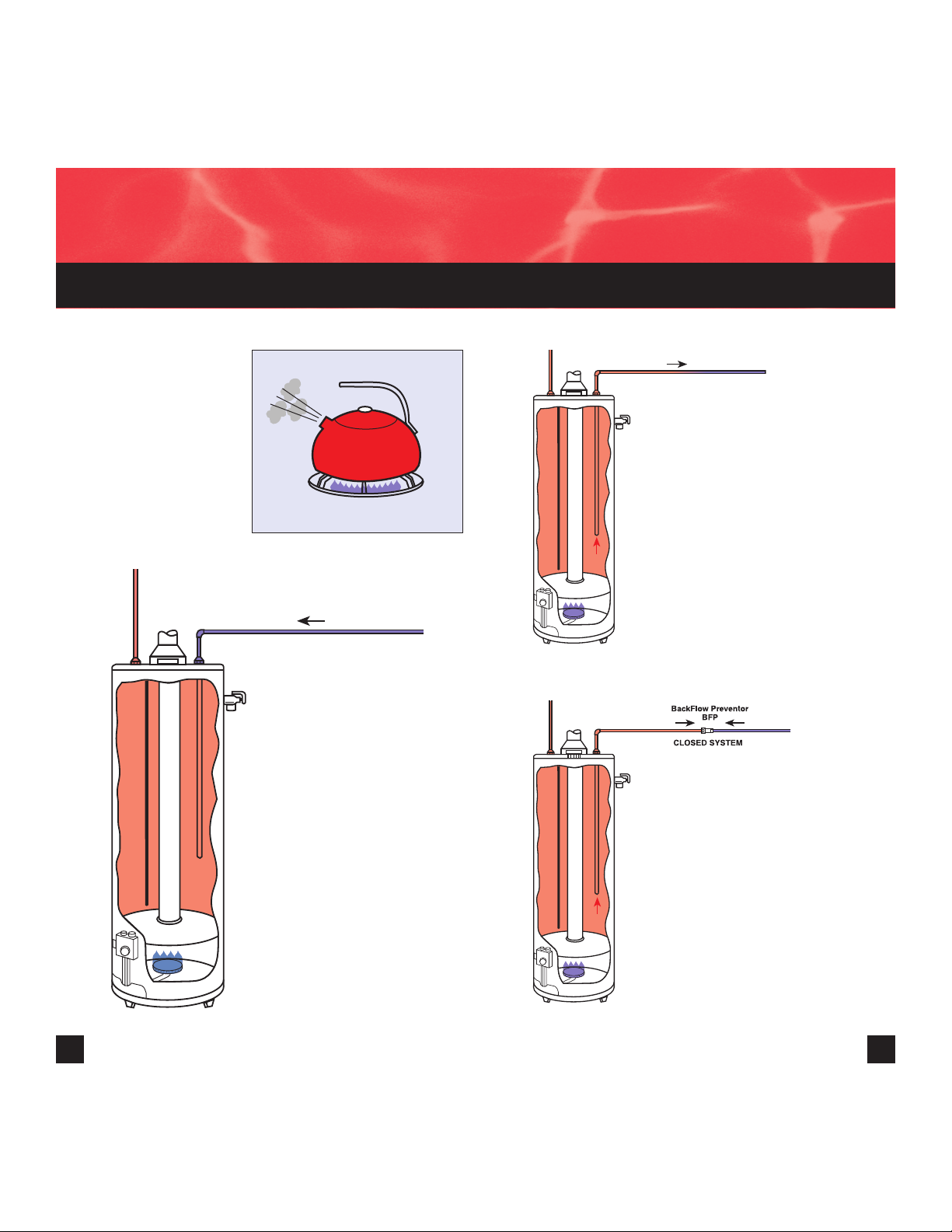
It expands! Reacting
to physical law, water
expands in volume as
its temperature rises.
In the "Good Old" days
Before the advent of
cross-connection control,
expanded water that
exceeded the capacity of
the water heater flowed
back to the city main,
where it easily dissipated.
It was "open" at the city
supply side of the system,
even though it was
"closed" on the system
side.
Cross connection
means "no return"
Today, with back flow
preventers, water meters
with check valves, and/or
pressure-reducing valves
without a bypass being
installed, expanded water
from a water heater
cannot return to the city
supply. It is now a closed
system, and expanded
water has no place to go.
When water is heated...
OPEN SYSTEM
COLD
WATER
SUPPLY
Page 3
4 5
Water is not
compressible
Since water completely
fills the water heater
and system piping before
recovery starts, and since
it can't be compressed,
the expanded volume,
even though small, has no
place to go.
As a result, the expanding
water creates a rapid
and dangerous pressure
increase in the water
heater and system piping,
much like the action of a
hydraulic ram.
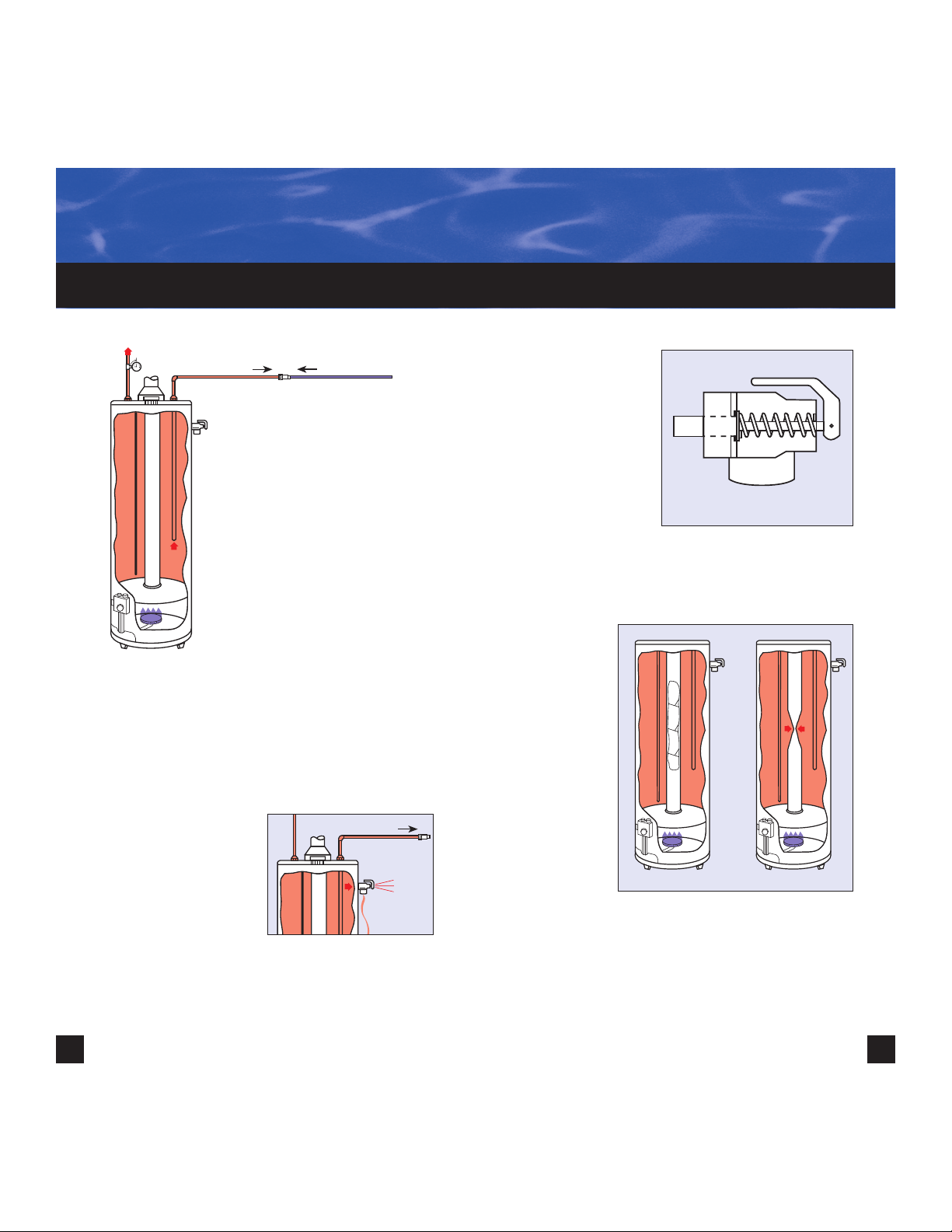
So "pop" goes the relief valve
The setting on a temperature & pressure safety
relief is quickly reached,
and the relief valve
opens, losing heater
water down the drain or,
more often than not, all
over the floor.
The illogical practice of operating your safety valve
once or twice a day is not only wasteful (you paid to
heat the water that went down the drain), it's also
dangerous.
First of all, the T & P
relief valve you
installed serves as
an emergency control only. It was never
designed as an
operating control.
Once a safety valve
is used on a daily
basis, it isn't that
safe.
Deposits on the seat... deteriorating springs... wearand-tear erosion can wear out a relief valve in no time
at all.
Dangerous
pressures
before relief
What most
people don't
realize is that
dangerous
conditions can exist during thermal expansion long
before the relief valve operates.
Internal pressures repeatedly occurring during recovery
periods can collapse the center flue of a gas-fired water
heater, creating a hazardous presence of deadly carbon
monoxide gas, or even a water-heater explosion.
DANGER!
BACK FLOW PREVENTER
BFP
LOST
BTUs
Page 4

6 7
Even though the relief valve operates during each
recovery period, high internal pressures occurring over
and over again can accelerate tank leakage and shorten water-heater life, no matter how it is fired.
Controlled Pressure Rise
During Thermal Expansion
The best solution to thermal expansion is to control
the pressure it generates within a safe operating
range, well below the emergency setting of a relief
valve. This allows thermal expansion to occur without
causing a dangerous increase in pressure.
Solution
SAFE
RANGE
150 PSIG
Page 5

8
9
AIR
This is easily accomplished by adding an
expansion tank with a
sealed-in, compressible
air cushion, which will
compress as thermal
expansion occurs, providing the place for the
expanded volume of
water to go during
recovery.
By sizing the air cushion
according to Boyle's
Law, we can select
the maximum pressure
on the system when
the total amount of
expanded water has
been generated.
When hot water is used
in the system, the pressurized air cushion
forces hot water back
into the system for use,
not waste.
The thermal expansion tank features the sealed-in air
cushion, pre-charged to the minimum system pressure before recovery is started. A rugged butyl
diaphragm seals in the air cushion and also separates
air from hot domestic water to prevent air from being
dissolved by hot system water.
Finally, on the water side of the expansion tank is a
separate, rigid polypropylene liner so fresh, corrosive,
domestic hot water can be handled without fear of
corrosion and leaks.
1. System
Connection
2. Separate, rigid
polypropylenelined water
reservoir (NSF
listed)
3. Heavy-duty
butyl diaphragm
4. Sealed-in,
permanent air
charge
5. Welded steel
pressure support domes
6. Air charging
valve
CUSHION
EXPANDED WATER
AIR
CUSHION
AIR
CUSHION
Page 6

10 11
Sizing charts based on:
• Precharge matched to incoming supply
pressure prior to installation
• Incoming water temperature 40°F
• 150psi T & P safety relief valve
AMTROL’s Therm-X-Trol
®
brochure MC#4090
contains precise sizing guidelines for sytems not
covered in the above charts.
The thermal-expansion tank for domestic water
heaters, sized right, is the only logical answer to the
growing problem of thermal expansion in water
heaters protected by BFP, check valves or pressurereducing valves. A simple installation to the supply
side on the water heater, this small tank will eliminate
the dangerous condition so that the relief valve will not
open during normal heating cycles.
Water Heater*
Size (gals.)
Static Supply Pressure (psi)
40
60
**
80
40 ST-5 ST-5 ST-5
50 ST-5 ST-5 ST-5
60 ST-5 ST-5 ST-8
80 ST-8 ST-8 ST-12
120 ST-12 ST-12 ST-25V
Max. Temp. Setting 140°F
BACK FLOW PREVENTER
BFP
Water Heater*
Size (gals.)
Static Supply Pressure (psi)
40
60
**
80
40 ST-5 ST-5 ST-5
50 ST-5 ST-5 ST-8
60 ST-8 ST-8 ST-8
80 ST-8 ST-8 ST-12
120 ST-12 ST-12 ST-25V
Max. Temp. Setting 150°F
Water Heater*
Size (gals.)
Static Supply Pressure (psi)
40
60
**
80
40 ST-8 ST-8 ST-8
50 ST-8 ST-8 ST-12
60 ST-8 ST-12 ST-25V
80 ST-12 ST-25V ST-25V
120 ST-25V ST-25V ST-25V
Max. Temp. Setting 180°F
Page 7

MC# 8550 PN: 9015-612 (06/07)
®
Corporate Headquarters
1400 Division Road
West Warwick, RI 02893
Telephone: 401-884-6300
Fax: 401-884-5276
AMTROL Canada, Ltd.
275 Shoemaker Street
Kitchener, Ontario N2E 3B3
Telephone: 519-478-1138
Fax: 519-748-1138
www.amtrol.com
12
 Loading...