


AMTROL PRESSURISER®
WATER PRESSURE BOOSTER SYSTEM
WITH GUARDIAN CP™ CONTROL
INSTALLATION & OPERATION INSTRUCTIONS
Models RP-10HP, RP-15HP and RP-25HP
NOTE: Inspect for shipping damage. Notify freight carrier or store where purchased immediately if damage is present. To avoid risk of personal injury and property damage, if the product appears to be malfunctioning or shows signs of corrosion, call a qualified professional immediately. Current copies
of the product manual can be viewed at www.amtrol.com. Use proper safety equipment when installing.
THIS IS THE SAFETY ALERT SYMBOL. IT IS USED TO ALERT YOU TO POTENTIAL PERSONAL INJURY AND OTHER HAZARDS. OBEY ALL SAFETY MESSAGES THAT FOLLOW THIS SYMBOL TO REDUCE THE RISK OF PERSONAL INJURY AS WELL AS PROPERTY DAMAGE.
USE ONLY WITH POTABLE WATER SYSTEMS.
 Do not operate in a setting with freezing temperatures or where the temperature can exceed 200°F and do not exceed the maximum working pressure specified for this Product.
READ CAREFULLY THE PRODUCT  INSTALLATION & OPERATION INSTRUCTIONS. FAILURE TO FOLLOW THE INSTRUCTIONS AND WARNINGS MAY RESULT IN SERIOUS OR FATAL INJURY AND/OR PROPERTY DAMAGE, AND WILL VOID THE PRODUCT WARRANTY. THIS PRODUCT MUST BE INSTALLED BY A QUALIFIED PROFESSIONAL. FOLLOW ALL APPLICABLE LOCAL AND STATE CODES AND REGULATIONS. IN THE ABSENCE OF SUCH CODES, FOLLOW THE CURRENT EDITIONS OF THE NATIONAL PLUMBING CODE AND NATIONAL ELECTRIC CODE, AS APPLICABLE.
This Product, like most Products under pressure,  may over time corrode, weaken and burst or explode, causing serious or fatal injury, leaking or flooding and/or property damage. To minimize risk, a licensed professional must install and periodically inspect and service the Product. A drip pan connected to an adequate drain must be installed if leaking or flooding could cause property damage. Do not locate in an area where leaking could cause property damage to the area adjacent to the appliance or to lower floors of the structure.
CALIFORNIA PROPOSITION 65 WARNING! This product contains a chemical known by the State of California to cause cancer and to cause birth defects or other reproductive harm. (California Installer/Contractor - California law requires that this notice be given to consumer/end user of this product.) For more information: www.amtrol.com/prop65.html
RUPTURE OR EXPLOSION HAZARD. Do not  expose Product to freezing temperatures or temperatures in excess of 200°F. Do not adjust the pre-charge or re-pressure this Product except during installation or regular inspection.
Replace the Product and do not adjust the precharge if corroded, damaged or with diminished integrity. Adjustments to pre-charge must be done at ambient temperature only. Failure to properly size the Product or follow these instructions may result in excessive strain on the system and may lead to Product failure, serious or fatal personal injury, leakage and/ or property damage.
A relief valve must be installed to prevent pressure  in excess of local code requirement or maximum working pressure designated in the Product Manual, whichever is less. At least once every 3 years or if discharge is present, a licensed contractor should inspect the temperature and pressure relief valve and replace if corrosion is evident or the valve does not function. FAILURE
TO INSPECT THIS VALVE AS DIRECTED COULD RESULT IN UNSAFE TEMPERATURE OR PRESSURE BUILD-UP WHICH CAN RESULT IN PRODUCT FAILURE, SERIOUS INJURY OR DEATH AND/ OR SEVERE PROPERTY DAMAGE AND VOID THE PRODUCT WARRANTY.
Chlorine & Aggressive Water: The water quality can significantly influence the life of this Product.
You should test for corrosive elements, acidity, total solids and other relevant contaminants, including chlorine and treat your water appropriately to insure satisfactory performance and prevent premature failure.
PLEASE READ THE FOLLOWING INSTRUCTIONS CAREFULLY
IMPORTANT GENERAL SAFETY INFORMATION -
ADDITIONAL SPECIFIC SAFETY ALERTS APPEAR IN THE FOLLOWING INSTRUCTIONS.
If the control is set too high or the pump is running  when the water supply is shut off and there is no demand on the system, the pump will run continuously, can overheat and become damaged, potentially resulting in product failure, leaking and/or rupture.
All wire and fuse sizings are preliminary  recommendations only. For your safety, local codes, and in their absence, national codes must be followed to minimize the risk of electric shock, property damage or personal injury.
The pump motor is designed for use with single  phase, 60Hz ac. Use with any other type of power will cause damage to the motor. The pump models RP-10HP, RP-15HP and RP25-HP are pre-wired for 115 vac; however, they can be rewired to be used with 230 vac. Consult motor nameplate for the wiring diagram.
The power for your pump must be on a dedicated  circuit. In addition, a shut off switch should be visible and near the pump. Use a 20 amp circuit.
Before attempting any service and disassembly,  shut off power to the pump. Ensure power is disconnected prior to removing motor. Ensure power is disconnected
before cleaning is attempted.
Grounding of the pump is essential for your  protection and the protection of the motor. All wiring should be completed by a licensed electrician, and in accordance with local codes or in their absence, the National Electrical Code. Before starting the wiring installation, disconnect all power to the circuit to be
used for the AMTROL Pressuriser®.
The AMTROL Pressuriser® should only be  connected to a municipal, cold water supply, and in systems with a minimum pressure of 10 psig at all times, measured under flow at the tap closest to the location of the AMTROL Pressuriser® installation.
Sizing Chart
|
Minimum |
Minimum |
Minimum |
|
|
Amtrol |
Flow Rate |
Flow Pressure |
Water |
||
Incoming |
|||||
Pressuriser® |
From City |
From City |
Meter |
||
|
Supply |
Supply |
Pipe Size |
|
|
|
|
|
|||
RP-10HP |
10 gpm |
10 psig |
3/4" |
3/4" |
|
RP-15HP |
15 gpm |
10 psig |
1" |
1" |
|
RP-25HP |
25 gpm |
10 psig |
1 1/4" |
1 1/4" |
Metal piping must be used for all inlet and outlet lines to the unit.
Do not oversize pump. Inadequate water supply will result in poor performance and pump damages.
Pre-Installation
•DO NOT USE FOR PRE-HEATED WATER SUPPLIES;
•DO NOT USE FOR ANYTHING EXCEPT COLD WATER (AMBIENT TEMPERATURE NOT TO EXCEED 100° F);
•DO NOT USE IN SYSTEMS WHERE LOW PRESSURE IS
DUE TO LEAKS OR WHERE LEAKS IN THE PLUMBING
SYSTEM MAY EXIST;
•DO NOT USE IN SYSTEMS WHERE THE WATER SUPPLY CAN DROP BELOW 10 PSIG;
•DO NOT USE IN SERIES WITH ANOTHER PUMP (SUCH AS IN PRIVATE WELL WATER SYSTEMS);
•DO NOT RE-PRESSURIZED TANK AFTER INITIAL INSTALLATION;
•DO NOT PIPE EXCEPT WITH METAL PIPING AT INLET
AND OUTLETS.
The system must be placed indoors only on a solid level surface with a drip pan piped to a drain with adequate capacity for large volumes of water in the event the system ruptures or fails. Consider the risks posed by tanks under pressure and the potential for leaking and/or flooding damage in selecting the location. The unit must not be placed in an environment that would expose the water in the tank to temperatures below freezing or in excess of 100° F. Figure 1
Be sure to leave a minimal clearance of 12” around the unit for access should field adjustments be necessary in the future and to permit maintenance and inspection (Figure 1).
12"
Amtrol Pressuriser®
Installation
1.Remove protective air valve cap.
2.Check pre-charge pressure (pressure should be + or – 10% of the factory setting). Factory pre-charge is 38 psig.
3.Release or add air as necessary to make the pre-charge pressure 2 psig below the pressure switch pump cut-in setting.
4.Replace protective air valve cap. (Remove air valve label, replace protective air valve cap, peel off backing of label and apply on air valve cap.)
MINIMUM SUPPLY LINE AND METER SIZE FOR  THE RP-10HP IS 3/4", THE RP-15HP IS 1" AND THE RP-25HP IS 11/4". THIS APPLIES TO ALL LINES INCLUDING THOSE USED WITH THE WATER METER OR FITTINGS BEFORE THE PUMP. CONTACT FACTORY IF MINIMUM FITTING/LINE SIZE IS BELOW THE ABOVE NUMBERS.
5. Install a SPRING LOADED CHECK VALVE in the city supply line on the suction side of the pump along with a shut-off valve. Failure to do so will result in premature failure of the AMTROL Pressuriser due to excessive pump cycling.
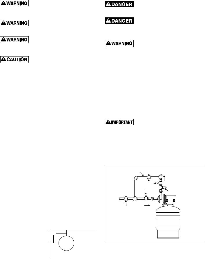
6. Install a by-pass loop (Figure 2).
Figure 2
BYPASS |
TO SYSTEM |
RP-10HP |
LOOP |
|
RP-15HP |
|
|
|
|
FLOW |
RP-25HP |
|
SHUT-OFF |
|
|
VALVES |
|
|
PRESSURE |
|
|
RELIEF |
|
|
VALVE |
|
CITY |
|
|
WATER |
|
|
SUPPLY |
|
|
SPRING |
FLOW |
|
CHECK VALVE |
|
|
|
|
7.Pipe the city supply after the shut-off valve to the suction side of the pump, as shown.
8.Connect the house supply line using a 100 psig maximum relief valve as shown (Figure 2). It is important that the pressure relief valve be installed on the pump discharge prior to any
shut off valves.
 Loading...