

Amtrol BoilerMate RTR, WH-7, BoilerMate Top Down, WH-9 User Manual
INSTALLATION, OPERATION
West Warwick, Rhode Island 02893
& MAINTENANCE
INSTRUCTIONS
BOILERMATE
INDIRECT-FIRED WATER HEATERS
®
MODELS COVERED:
• WH-7 & 9 Classic Series
• Top Down
• RTR models
• WHS Premier Series
™
TD Series
MODELS CODES:
P: Packaged with circulator & Smart Control
L: Less Circulator, with Smart Control
Z: Dial Aquastat
C: High-output commercial exchanger
DW: Double-wall heat exchanger
RTR: Pre-piped and wired
™
™
INSTALLER: LEAVE THIS MANUAL WITH THE OWNER
IMPORTANT GENERAL SAFETY INFORMATION - ADDITIONAL SPECIFIC SAFETY ALERTS APPEAR IN THE FOLLOWING
INSTRUCTIONS.
READ CAREFULLY THE PRODUCT INSTALLATION, OPERATING AND MAINTENANCE MANUAL. FAILURE
FATAL INJURY AND/OR PROPERTY DAMAGE, AND WILL VOID THE PRODUCT WARRANTY. THIS PRODUCT MUST BE
INSTALLED BY A QUALIFIED PROFESSIONAL. FOLLOW ALL APPLICABLE LOCAL AND STATE CODES AND REGULATIONS,
IN THE ABSENCE OF SUCH CODES, FOLLOW THE CURRENT EDITIONS OF THE NATIONAL PLUMBING CODE AND NATIONAL
ELECTRIC CODE, AS APPLICABLE.
THIS IS THE SAFETY ALERT SYMBOL. IT IS USED TO ALERT YOU TO POTENTIAL PERSONAL INJURY AND OTHER
HAZARDS. OBEY ALL SAFETY MESSAGES THAT FOLLOW THIS SYMBOL TO REDUCE THE RISK OF PERSONAL
INJURY AS WELL AS PROPERTY DAMAGE.
Part #: 9040-586 (07/08)
TO FOLLOW THE INSTRUCTIONS AND WARNINGS IN THE MANUAL MAY RESULT IN SERIOUS OR
The heat transfer medium must be water or other nontoxic fluid having a toxicity rating or class of 1, as
listed in Clinical Toxicology of Commercial Products, 5th edition. The pressure of the heat transfer
medium must be limited to 30 PSIG by an approved safety or relief valve.
1. TABLE OF CONTENTS
2. Pre-Installation Checklist .................................................
3. Required Components and Accessories Checklist .........
4. WH-7 & 9 Classic Series Piping Installation ....................
5. Top Down™ TD-Series Piping Installation ......................
6. Ready-To-Run RTR-Series Piping Installation ................
7. WHS Premier Series Piping Installation ........................
8. Wiring All Smart Control™ Models ...............................
9. Wiring All Dial Control Models (Except RTR Models) .........
2
3
4
6
8
10
12
20
2. PRE-INSTALLATION CHECKLIST
IMPORTANT STEPS AND DECISIONS REQUIRED BEFORE INSTALLATION
M THIS PRODUCT MUST BE INSTALLED AND
MAINTAINED BY A LICENSED PROFESSIONAL. IN
ADDITION TO THE INSTRUCTIONS IN THIS MANUAL,
FOLLOW ALL APPLICABLE LOCAL AND STATE CODES
OR IN THE ABSENCE OF SUCH CODES, THE CURRENT
EDITIONS OF THE NATIONAL PLUMBING CODE AND
THE NATIONAL ELECTRIC CODE.
M DRIP PAN AND DRAIN: This appliance should not
be installed in an area where leakage of the tank or
connections can result in damage to the area adjacent
to the appliance or to lower floors of the structure.
When such locations cannot be avoided, a suitable
drain pan, adequately drained and kept clear, must be
installed under the appliance.
M CAUTION: Determine whether your water is corrosive
or acidic, and that there are no suspended solids,
toxic or other substances or abnormally high chlorine
levels in the water that could damage or affect the
BOILERMATE
MODELS. Glycol is a hazardous substance. To avoid
seepage or leakage of glycol to surfaces where
humans or animals can ingest it, use glycol only in
double-walled units, so that any leaks will most likely
be released to the atmosphere. However, a leak to a
surface area may still occur, so any use of glycol must
be monitored closely and humans and animals should
be protected from contact with the unit.
or other space heating units or elements. Any
contaminants in the baseboard units will contaminate
the potable water in the BOILERMATE® and also
adversely affect its performance.
M Wiring Options. Select either a Non-Priority or Priority
System:
Two options are available when wiring the controls of the
BOILERMATE
distribution elements).
1. Non-Priority System - The controls of the
BOILERMATE
zone with a standard zone valve or a separate
circulator dedicated to the BOILERMATE
NOTICE: In this non-priority option, the BOILERMATE
will be supplied just as another zone. This means that if all
space heating zones call for hot boiler water at the same
®
or the rest of your plumbing system.
USE GLYCOL ONLY WITH
DOUBLE-WALLED HEAT EXCHANGER
Do not connect the BOILERMATE®
domestic supply with baseboard
®
in the space heating system (boiler and
®
must be wired as a separate heating
®
“zone”.
®
10. Wiring All Ready-To-Run (RTR) Models .......................
11. Startup Procedure For All Models ................................
12. Setting the Smart Control™ ..........................................
13. Troubleshooting .............................................................
14. Replacement Parts ........................................................
15. Cleaning the BoilerMate® Heat Exchanger ...................
16. General Safety Information ...........................................
time, the BOILERMATE
®
may not be supplied with enough
23
25
26
27
28
29
30
hot boiler water to “recover” adequately. The delivery of
domestic hot water will be diminished. In many, but not all
cases, this is not a problem because the routine oversizing
of boiler output is adequate for both loads.
2. Priority System - Under this wiring option the
BOILERMATE
®
will be supplied before space heating.
In limited circumstances, space
heating can be lost in the home in
this priority mode. Any demand for space heating is
postponed until the BOILERMATE
®
has reached its set
temperature. This delay in supplying the space heating
zones is usually not noticed by the inhabitants of the
living spaces. However, in the event of certain
malfunctions such as circulator or thermostat failure,
space heating could be delayed indefinitely. If
undetected and uncorrected, freezing damage to piping
could result.
M Select Circulator versus Zone Valve
The flow of hot boiler water to the BOILERMATE
®
can
be controlled with either a motorized zone valve or a
circulator.
1. Separate circulator. The recommended way to
provide adequate flow through the BOILERMATE
®
heat exchanger is to use a separate dedicated
circulator with a minimum flow rate of 5 gpm. This
option may be used even though the heating system
utilizes zone valves.
2. Zone valve (system flow of 4-8 gpm). If a zone valve
is to be used, a minimum flow rate of 5 gpm with all
zones in use is required. A full-port zone valve should
be used.
M All installations require a low-water cut-off or automatic fill
valve on your boiler system to reduce the risk of boiler water
loss.
M Steam boiler installations require a low-water cut-off which
is also required by most codes.
M Installation of a vacuum breaker is required to prevent
damage to the BOILERMATE
®
when drained. There must
be no valves installed between the vacuum breaker and
BOILEMATE®.
-2-
3. REQUIRED COMPONENTS AND
ACCESSORIES CHECKLIST
SHUTOFF VACUUM RELIEF THERMAL EXPANSION
MODEL CIRCULATOR ZONE VALVE* VALVE BREAKER VALVE TANK DRAIN
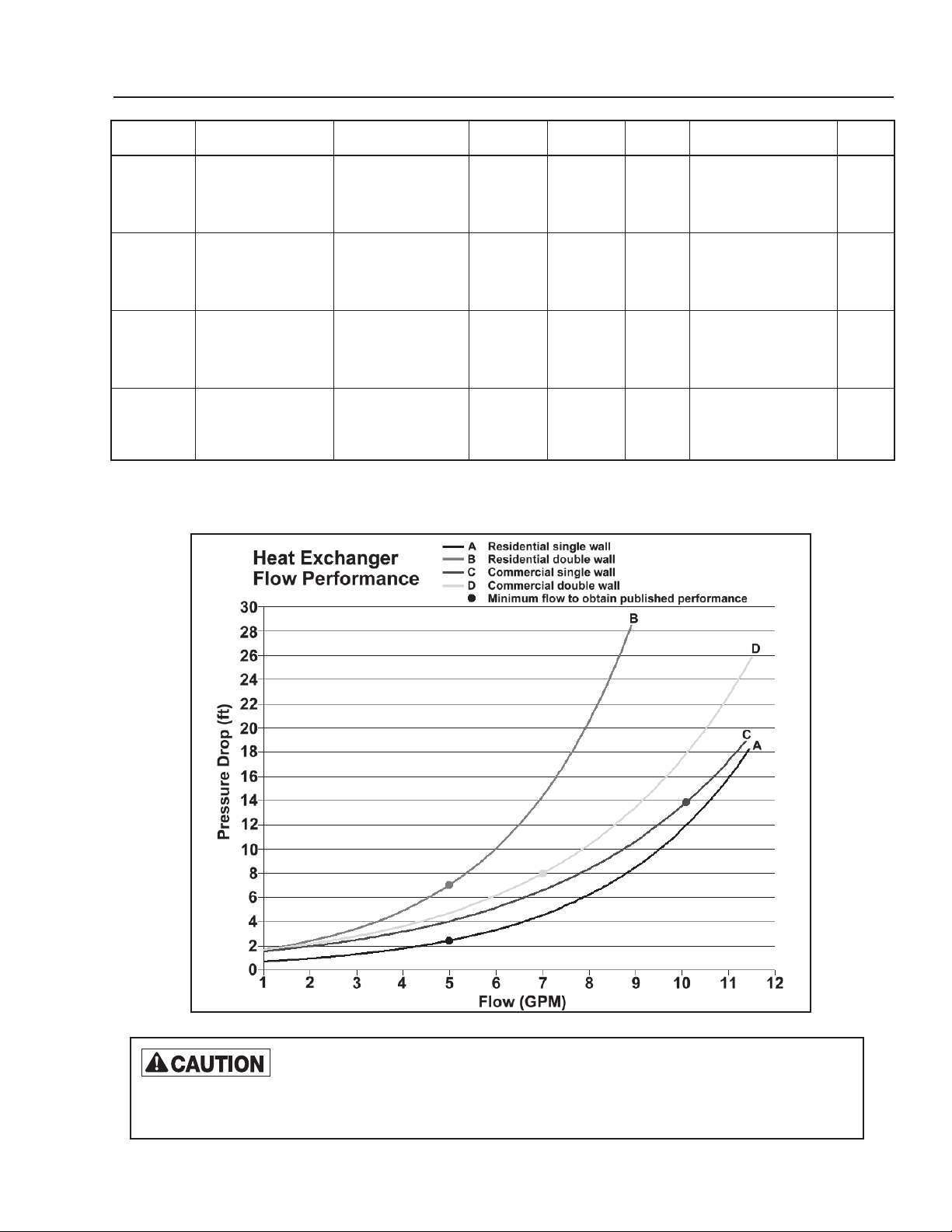
Residential = 5GPM *If Circulator not used Required
WH SERIES Commercial = 10GPM 3/4” Full Port 4 1 Included (See Therm-X-Trol® Included
Except “P” Models or 1” STD Sizing Guide)
5GPM *If Circulator not used Required
TD SERIES Except “P” Models 3/4” Full Port 4 1 Included (See Therm-X-Trol® Included
or 1” STD Sizing Guide)
Required
RTR SERIES Included N/A 4 1 Included (See Therm-X-Trol® Included
Sizing Guide)
Residential = 5GPM *If Circulator not used Required
WHS SERIES Commercial = 10GPM 3/4” Full Port 4 1 Included (See Therm-X-Trol® Included
Except “P” Models or 1” STD Sizing Guide)
ALL INSTALLATIONS REQUIRE TEFLON® SEALING TAPE OR PIPE DOPE FOR THREADED JOINTS.
SEE HEAT EXCHANGER PRESSURE DROP CHART TO DETERMINE PUMP HEAD REQUIREMENTS.
Use this chart to select the proper circulator for your BOILERMATE®.
If a steel hydropneumatic tank is in place, AMTROL® recommends replacing it with a
properly sized EXTROL
heat transfer problems can occur by causing air to be trapped in the heat exchanger. If the boiler system has
an EXTROL
EXTROL
®
or Radiant EXTROL® expansion tank and the boiler temperatures are being changed, resize the
®
or Radiant EXTROL® expansion tank.
®
or Radiant EXTROL® expansion tank. Otherwise, significant
-3-
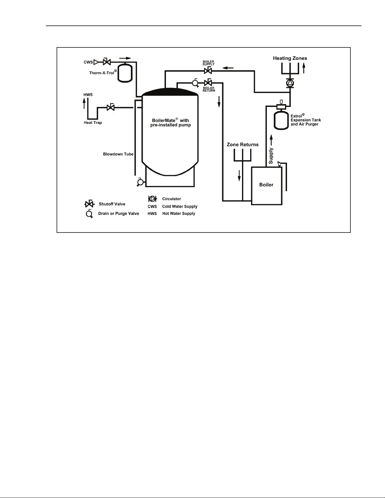
4. WH-7 & 9 CLASSIC SERIES
PIPING INSTALLATION
DOMESTIC WATER PIPING
1. Thread the included 3/4” brass tee onto the pipe marked
COLD WATER.
2. Screw the
tee.
3. Connect the cold water supply to the remaining port on the
brass tee.
4. Temporarily attach the top tee fitting (with o-ring face seal)
to the union nut on top of the tank. Test fit the piping near
the tee before soldering. Remove the tee before soldering
connections to avoid damage to the top o-ring seal or
plastic liner.
Note: Do not solder piping within 24 inches of the top tee
fitting while attached to the tank.
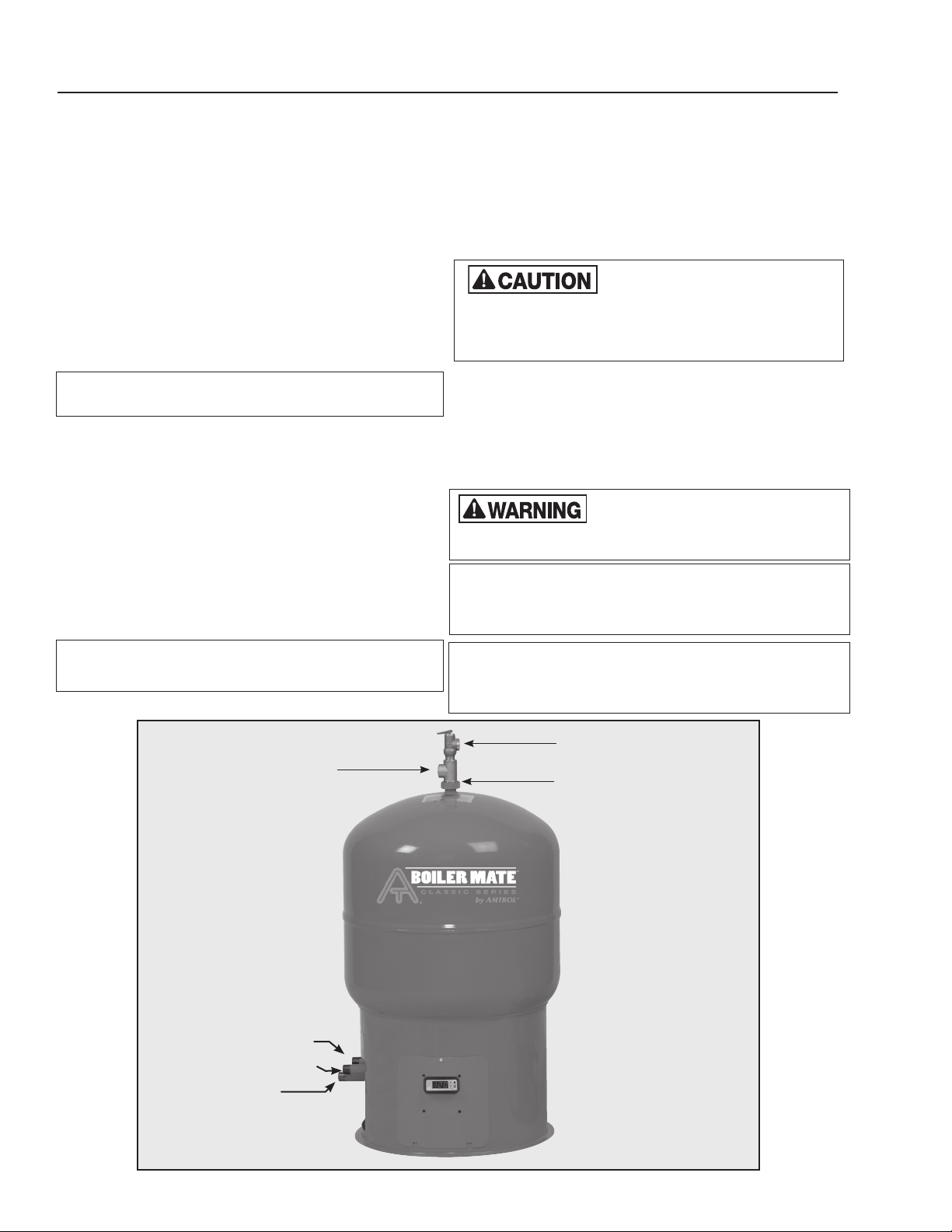
5. Make an 8-inch “heat trap” as shown in the diagram.
This will reduce standby losses from heat migrating up
the piping. Continue this line to the domestic hot water
system.
6. Install the included T&P relief valve on the top port of the
top tee connection. Plumb a blowdown tube to within 6
inches of a floor drain or as directed by plumbing code.
7. When all domestic water piping is complete, open the cold
water supply and allow some water to enter the tank. Look
and listen for signs of leaks and repair as necessary before
continuing.
Note: If installing on a city supply, ensure a dedicated
Thermal Expansion tank (Therm-X-Trol
used.
3
/4” drain valve into the opposite end of the brass
®
or equivalent) is
BOILER PIPING
1. Plumb the circulator or zone valve on the BOILER SUPPLY
line. If using a separate circulator, the pump flange
can be mounted directly to the threaded pipe marked
BOILER SUPPLY. Alternately, the circulator can be placed
anywhere on the boiler supply line.
2. Pipe the BOILER RETURN connection to the boiler return
line.
Be sure the return line is NOT
any heating circulators. This may require moving the
heating circulator off the boiler tapping on packaged
boilers. Failure to do so will result in overheating and
tank damage when the heating system is in operation.
3. Install a weighted flow check on the boiler return line. This
is not necessary on systems utilizing a zone valve to control
the BoilerMate® temperature.
4. After completing the boiler piping, slowly open the boiler fill
valve and pressurize the BoilerMate® loop. Check for leaks
and repair as necessary. Proceed to the appropriate wiring
section in this manual.
required with the BoilerMate
forth in the THERM-X-TROL
Clearance From Combustible Surfaces
LEFT SIDE ............1”
RIGHT SIDE ...........1”
TOP .................9”
Recommended Clearance For Servicing
LEFT .................12”
RIGHT................12”
FRONT ...............30”
plumbed to the suction side of
If installing on city water supply a
properly sized THERM-X-TROL
®
and should be installed as set
®
product installation manual.
®
is
REAR ................1”
FLOOR ...............0”
FRONT ...............1”
HEAD ROOM ..........9”
REAR ................1”
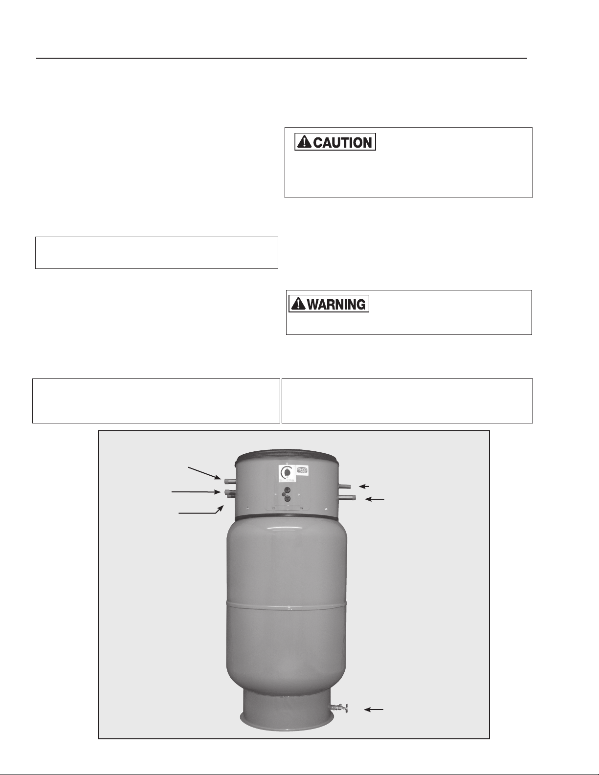
HOT WATER OUTLET
BOILER RETURN (Top Left)
BOILER SUPPLY (Top Right)
COLD WATER INLET
(Bottom Center)
T&P RELIEF VALVE
UNION NUT
-4-
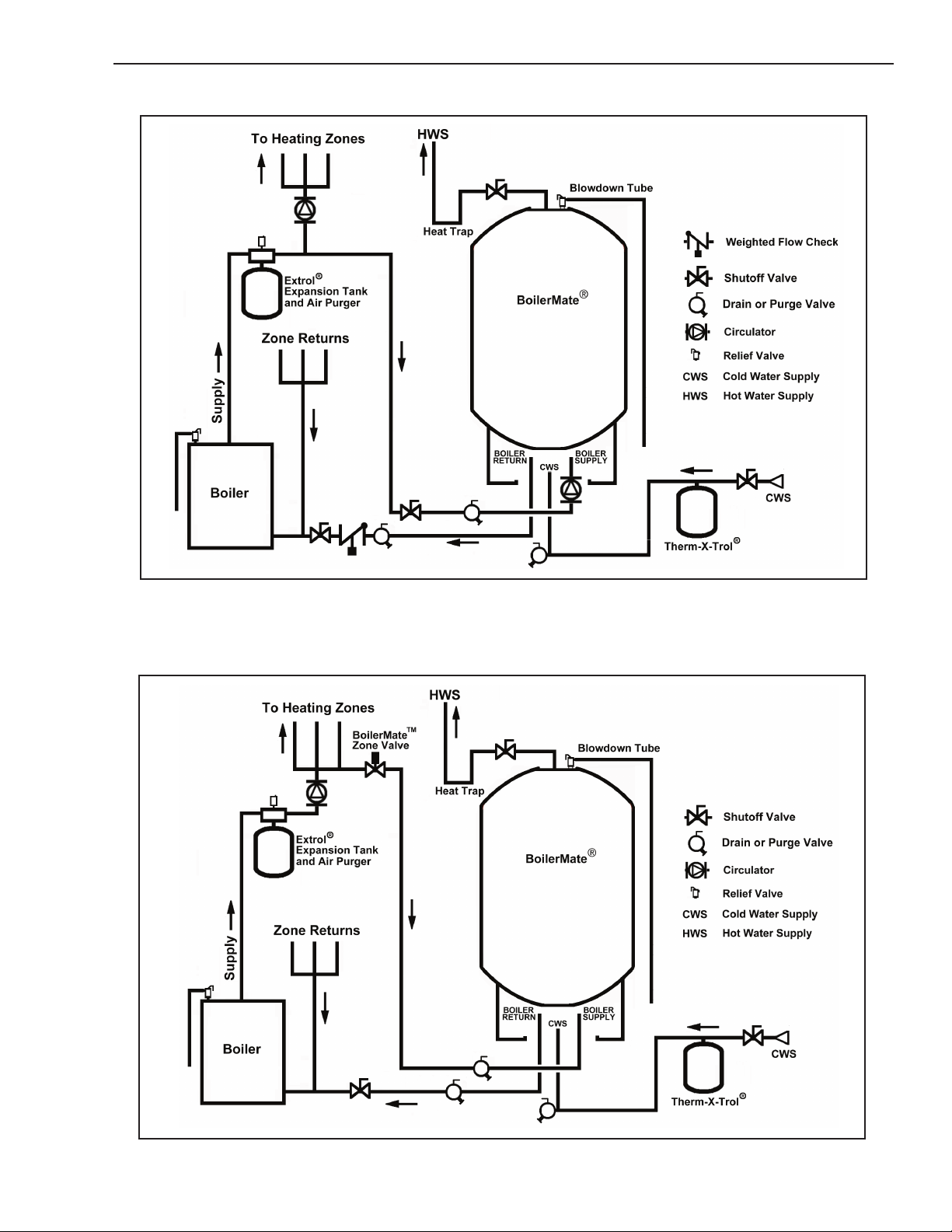
PIPING USING SEPARATE CIRCULATOR PUMP (RECOMMENDED)
PIPING USING ZONE VALVE WITH EXISTING HEATING SYSTEM CIRCULATOR
-5-
5. TOP DOWN™ TD-SERIES
PIPING INSTALLATION
DOMESTIC WATER PIPING
1. Connect the cold water supply to the pipe labeled COLD
WATER
2. Connect the HOT WATER piping to the domestic hot water
system.
3. Make an 8-inch “heat trap” on the HOT WATER outlet as
shown in the diagram. This will reduce standby losses from
heat migrating up the piping.
4. When all domestic water piping is complete, open the cold
water supply and allow some water to enter the tank. Look
and listen for signs of leaks and repair as necessary before
continuing.
Note: If installing on a city supply, ensure a dedicated
Thermal Expansion tank (Therm-X-Trol
®
or equivalent) is
used.
5. Install a blowdown tube on the T&P relief valve outlet.
Plumb to within 6 inches above a floor drain or as directed
by plumbing code.
BOILER PIPING
1. Plumb the circulator or zone valve on the BOILER SUPPLY
line. If using a separate circulator, the pump flange
can be mounted directly to the threaded pipe marked
BOILER SUPPLY. Alternately, the circulator can be placed
anywhere on the boiler supply line.
2. Pipe the BOILER RETURN connection to the boiler return
line.
Be sure the return line is NOT
plumbed to the suction side of any
heating circulators. This may require moving the
heating circulator off the boiler tapping on packaged
boilers. Failure to do so will result in overheating and
tank damage when the heating system is in
operation.
3. Install a weighted flow check on the boiler return line. This
is not necessary on systems utilizing a zone valve to control
the BoilerMate
4. After completing the boiler piping, slowly open the boiler fill
valve and pressurize the BoilerMate
®
temperature.
®
loop. Check for leaks
and repair as necessary. Proceed to the appropriate wiring
section in this manual.
If installing on city water supply a
properly sized THERM-X-TROL
required with the BoilerMate
forth in the THERM-X-TROL
®
and should be installed as set
®
product installation manual.
®
is
Clearance From Combustible Surfaces
LEFT SIDE ............1”
RIGHT SIDE ...........1”
TOP .................9”
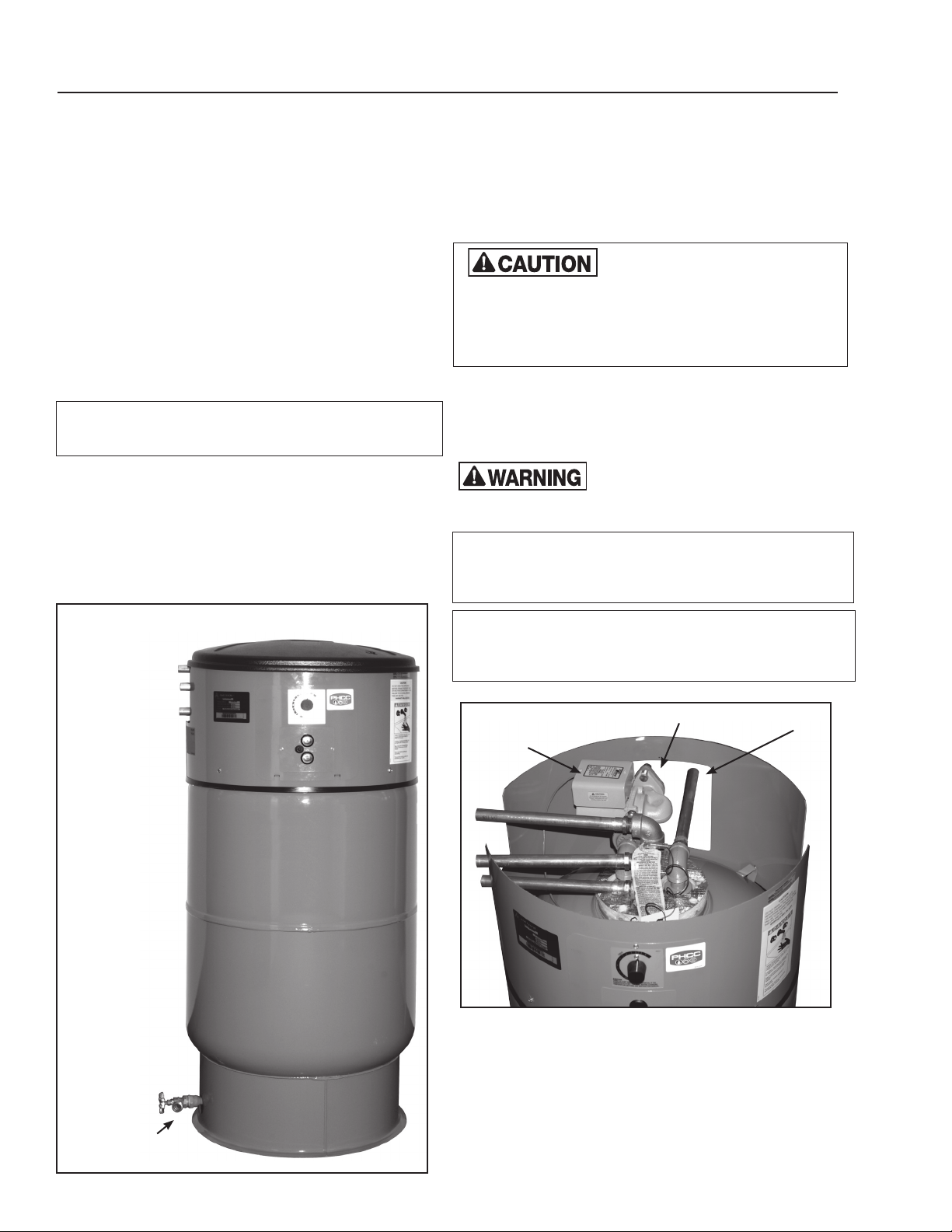
COLD WATER INLET
(Top Center)
BOILER SUPPLY
(Bottom Right)
BOILER RETURN
(Bottom Left)
REAR ................1”
FLOOR ...............0”
FRONT ...............1”
Recommended Clearance For Servicing
LEFT .................12”
RIGHT................12”
HEAD ROOM ..........9”
REAR ................1”
FRONT ...............30”
T&P RELIEF VALVE OUTLET
HOT WATER OUTLET
-6-
DRAIN VALVE
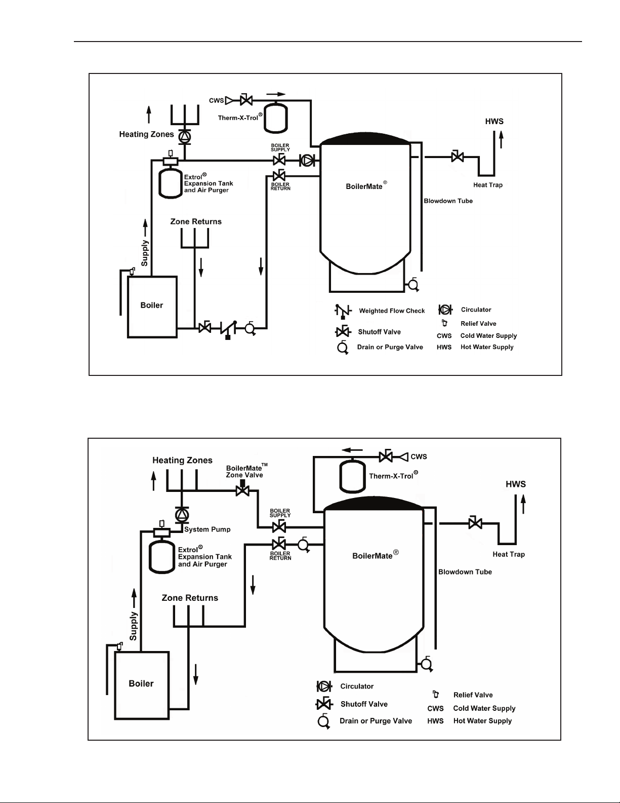
PIPING USING SEPARATE CIRCULATOR PUMP (RECOMMENDED)
PIPING USING ZONE VALVE WITH EXISTING HEATING SYSTEM CIRCULATOR
-7-
6. READY-TO-RUN RTR-SERIES
PIPING INSTALLATION
DOMESTIC WATER PIPING
1. Connect the cold water supply to the pipe labeled COLD
WATER.
2. Connect the HOT WATER piping to the domestic hot water
system.
3. Make an 8-inch “heat trap” on the HOT WATER outlet as
shown in the diagram. This will reduce standby losses from
heat migrating up the piping.
4. When all domestic water piping is complete, open the cold
water supply and allow some water to enter the tank. Look
and listen for signs of leaks and repair as necessary before
continuing.
Note: If installing on a city supply, ensure a dedicated
Thermal Expansion tank (Therm-X-Trol
used.
5. Install a blowdown tube on the T&P relief valve outlet.
Plumb to within 6 inches above a floor drain or as directed
by plumbing code.
COLD WATER INLET
T&P RELIEF VALVE
HOT WATER OUTLET
OUTLET
®
or equivalent) is
BOILER PIPING
1. Plumb the BOILER SUPPLY line. The circulator and flow
check are factory installed
2. Pipe the BOILER RETURN connection to the boiler return
line.
Be sure the return line is NOT
heating circulators. This may require moving the
heating circulator off the boiler tapping on packaged
boilers. Failure to do so will result in overheating and
tank damage when the heating system is in
operation.
3. After completing the boiler piping, slowly open the boiler fill
valve and pressurize the heat exchanger loop. Check for
leaks and repair as necessary. Proceed to the appropriate
wiring section in this manual.
required with the BoilerMate
forth in the THERM-X-TROL
Clearance From Combustible Surfaces
LEFT SIDE ............1”
RIGHT SIDE ...........1”
TOP .................9”
Recommended Clearance For Servicing
LEFT .................12”
RIGHT................12”
FRONT ...............30”
CIRCULATOR
plumbed to the suction side of any
If installing on city water supply a
properly sized THERM-X-TROL
®
and should be installed as set
®
product installation manual.
REAR ................1”
FLOOR ...............0”
FRONT ...............1”
HEAD ROOM ..........36”
REAR ................1”
BOILER SUPPLY
BOILER RETURN
®
is
DRAIN VALVE
TOP VIEW
SIDE VIEW
-8-
PIPING MODELS WITH PRE-INSTALLED CIRCULATOR W/INTEGRAL FLOW CHECK
-9-
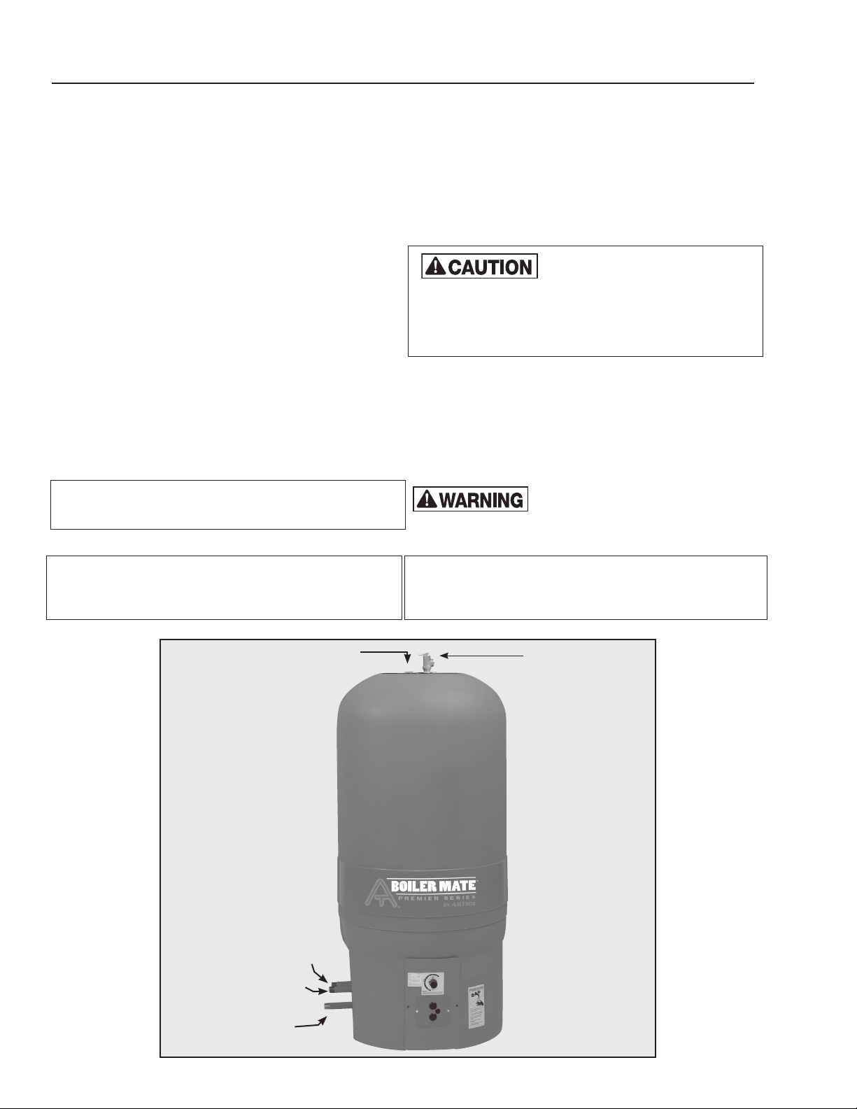
7. WHS PREMIER SERIES
PIPING INSTALLATION
DOMESTIC WATER PIPING
1. Thread the included brass tee onto the pipe marked COLD
WATER.
2. Screw the drain valve into the opposite end of the brass
tee
3. Connect the cold water supply to the remaining port on the
brass tee
4. Thread the included T&P Safety Relief Valve into the offset
3
/4” port on the top plate. Install a blowdown tube to within
6 inches of a floor drain or as directed by plumbing code.
5. Connect the center hot water outlet port on the top plate to
the domestic hot water system.
6. Make an 8-inch “heat trap” as shown in the diagram. This
will reduce standby losses from heat migrating up the
piping.
7. When all domestic water piping is complete, open the cold
water supply and allow some water to enter the tank. Look
and listen for signs of leaks and repair as necessary before
continuing.
Note: If installing on a city supply, ensure a dedicated
Thermal Expansion tank (Therm-X-Trol
used.
®
or equivalent) is
BOILER PIPING
1. Plumb the circulator or zone valve on the BOILER SUPPLY
line. If using a separate circulator, the pump flange
can be mounted directly to the threaded pipe marked
BOILER SUPPLY. Alternately, the circulator can be placed
anywhere on the boiler supply line.
2. Pipe the BOILER RETURN connection to the boiler return
line.
Be sure the return line is NOT
heating circulators. This may require moving the
heating circulator off the boiler tapping on packaged
boilers. Failure to do so will result in overheating and
tank damage when the heating system is in
operation.
3. Install a weighted flow check on the boiler return line. This
is not necessary on systems utilizing a zone valve to control
the BoilerMate
4. After completing the boiler piping, slowly open the boiler fill
valve and pressurize the BoilerMate
and repair as necessary. Proceed to the appropriate wiring
section in this manual.
required with the BoilerMate
forth in the THERM-X-TROL
plumbed to the suction side of any
®
temperature.
®
loop. Check for leaks
If installing on city water supply a
properly sized THERM-X-TROL
®
and should be installed as set
®
product installation manual.
®
is
Clearance From Combustible Surfaces
LEFT SIDE ............1”
RIGHT SIDE ...........1”
TOP .................9”
BOILER SUPPLY (Top Right)
REAR ................1”
FLOOR ...............0”
FRONT ...............1”
HOT WATER OUTLET
BOILER RETURN (Top Left)
Recommended Clearance For Servicing
LEFT .................12”
RIGHT................12”
HEAD ROOM ..........36”
REAR ................1”
FRONT ...............30”
T&P RELIEF VALVE
COLD WATER INLET
(Bottom Center)
-10-
 Loading...