


AMS Wireless Vibration Monitor
User Guide
User Guide
MHM-97927-PBF, Rev 1
August 2020

Copyright
©
2020 by Emerson. All rights reserved.
No part of this publication may be reproduced, transmitted, transcribed, stored in a retrieval system, or translated into any
language in any form by any means without the written permission of Emerson.
Disclaimer
This manual is provided for informational purposes. EMERSON MAKES NO WARRANTY OF ANY KIND WITH REGARD TO THIS
MATERIAL, INCLUDING, BUT NOT LIMITED TO, THE IMPLIED WARRANTIES OF MERCHANTABILITY AND FITNESS FOR A PARTICULAR
PURPOSE. Emerson shall not be liable for errors, omissions, or inconsistencies that may be contained herein or for incidental or
consequential damages in connection with the furnishing, performance, or use of this material. Information in this document is
subject to change without notice and does not represent a commitment on the part of Emerson. The information in this manual is
not all-inclusive and cannot cover all unique situations.
Patents
The product(s) described in this manual are covered under existing and pending patents.
Where to get help
Software Registration
Phone:
Toll free 888.367.3774, option 2 (U.S. and Canada)
+63.2.702.1111 (Rest of world)
Email:
Web:
wwcs.custserv@emerson.com
http://www.emerson.com/machineryhealthreg
Product Support
Emerson provides a variety of ways to reach your Product Support team to get the answers you need when you need them:
Phone
Toll free 800.833.8314 (U.S. and Canada)
+1.512.832.3774 (Latin America)
+63.2 702.1111 (Asia Pacific, Europe, and Middle East)
Email
Web
ap-sms@emerson.com
http://www.emerson.com/en-us/contact-us
To search for documentation, visit http://www.emerson.com.
To view toll free numbers for specific countries, visit http://www.emerson.com/technicalsupport.
2

User Guide Contents
MHM-97927-PBF August 2020
Contents
Chapter 1 Introduction.................................................................................................................. 5
1.1 Safety messages...............................................................................................................................5
1.2 Symbols............................................................................................................................................5
1.3 Considerations................................................................................................................................. 7
1.4 Return of materials...........................................................................................................................7
1.5 Overview.......................................................................................................................................... 9
1.6 Device variables..............................................................................................................................13
1.7 Variable mappings..........................................................................................................................14
Chapter 2 Configuration...............................................................................................................15
2.1 Setup overview...............................................................................................................................15
2.2 Pre-configuration........................................................................................................................... 16
2.3 Configuration overview.................................................................................................................. 17
2.4 Configuration with AMS Device Manager........................................................................................20
2.5 Configure with Trex Communicator................................................................................................37
2.6 Configuration options.................................................................................................................... 38
Chapter 3 Installation...................................................................................................................43
3.1 Device handling..............................................................................................................................43
3.2 Mounting tools and supplies...........................................................................................................43
3.3 Mounting mechanisms...................................................................................................................44
3.4 Mount the device........................................................................................................................... 48
3.5 Change the battery.........................................................................................................................49
Chapter 4 Operation.................................................................................................................... 51
4.1 Verify the device is operational.......................................................................................................51
4.2 Verify operation with Emerson Wireless Gateway...........................................................................51
4.3 Verify operation with AMS Trex Communicator..............................................................................52
4.4 Check device status........................................................................................................................53
4.5 Device variable ranges....................................................................................................................54
4.6 Device operating limits...................................................................................................................54
4.7 Clean the device............................................................................................................................. 54
Chapter 5 Overall Velocity, PeakVue, and temperature................................................................ 55
5.1 Overall Velocity.............................................................................................................................. 55
5.2 PeakVue......................................................................................................................................... 58
5.3 Temperature.................................................................................................................................. 62
Appendix A Specifications and reference data.................................................................................65
A.1 Functional specifications................................................................................................................ 65
A.2 Physical specifications.................................................................................................................... 66
A.3 Performance specifications............................................................................................................ 66
MHM-97927-PBF, Rev 1 iii

Contents User Guide
August 2020 MHM-97927-PBF
A.4 Radio specifications........................................................................................................................67
A.5 Device variable alert limits..............................................................................................................67
Appendix B Product certifications................................................................................................... 73
B.1 Approved manufacturing locations................................................................................................ 73
B.2 Wireless certifications.................................................................................................................... 73
B.3 Ordinary location certification (CSA)...............................................................................................75
B.4 CE mark..........................................................................................................................................75
B.5 Hazardous locations certifications.................................................................................................. 77
B.6 Waste Electrical and Electronic Equipment..................................................................................... 79
Appendix C Third-party licenses......................................................................................................81
C.1 Dust SmartMeshSDK C Library........................................................................................................81
Index .................................................................................................................................... 83
iv MHM-97927-PBF, Rev 1

User Guide Introduction
MHM-97927-PBF August 2020
1 Introduction
1.1 Safety messages
Instructions in this manual may require special precautions to ensure the safety of the
personnel performing the operations.
The AMS Wireless Vibration Monitor complies with Part 15 of the FCC Rules. Operation is
subject to the following conditions:
This device may not cause harmful interference, this device must accept any interference
received, including interference that may cause undesired operation.
This device must be installed to ensure a minimum separation of 20 cm from all persons.
Refer to the following safety messages before performing an operation preceded by the
warning symbol:
WARNING
Failure to follow these installation guidelines can result in death or serious injury. Only
qualified personnel should install the AMS Wireless Vibration Monitor.
Explosions could result in death or serious injury:
• Before connecting a Field Communicator in an explosive environment, make sure the
instruments are installed in accordance with applicable field wiring practices.
• Verify that the operating environment of the AMS Wireless Vibration Monitor is
consistent with the appropriate hazardous locations certifications.
1.2 Symbols
Note
This symbol marks passages that contain important information.
CAUTION
This symbol marks operations that can lead to malfunctions or faulty measurements, but
will not damage the device.
DANGER
This symbol indicates actions that can lead to property damage or personal injury.
The symbols on the device signify compliance to the following:
Ukraine Restriction of Hazardous Substances (RoHS)
MHM-97927-PBF, Rev 1 5

Introduction User Guide
August 2020 MHM-97927-PBF
Regulatory Compliance Mark Australia
China Restriction of Hazardous Substances (RoHS)
Lithium-ion cell recyclable
The documentation must be completely read and understood before installing and
commissioning the device. Observe all safety-related instructions in this document.
Waste Electronic and Electrical Equipment Directive
6 MHM-97927-PBF, Rev 1

User Guide Introduction
MHM-97927-PBF August 2020
1.3 Considerations
General
Electrical vibration sensors, such as accelerometers, produce low-level signals proportional
to their sensed vibration. With simple HART configuration, the monitor converts the lowlevel sensor signal to a wireless-enabled signal.
Commissioning
The monitor can be commissioned before or after installation. You can commission it on
the bench before installation to ensure proper operation and to be familiar with its
functions.
Make sure the instruments are installed in accordance with applicable field wiring
practices.
The AMS Wireless Vibration Monitor is powered whenever the battery is installed.
Installation
When choosing an installation location and position, provide ample access to the monitor.
The device should be mounted vertically, perpendicular to the shaft and on the bearing
case. Horizontal mounting is also an option. For more information, see Installation.
Battery
The AMS Wireless Vibration Monitor uses an off-the-shelf Tadiran TL-4920/VE battery.
The battery comes with the device but it is not connected when the device is shipped. You
need to connect the battery before configuring and installing the device.
Environmental
The monitor operates within specifications for ambient temperatures between –40°F and
185°F (–40°C and 85°C).
Verify that the operating environment of the monitor is consistent with the appropriate
hazardous location certifications.
1.4 Return of materials
You may need to ship the device to an Emerson Product Service Center for return or
replacement in case of warranty issues. Before shipping, contact Emerson Product Support
to obtain a Return Materials Authorization (RMA) number and receive additional
instructions.
Emerson Product Support contact information:
Phone
Email
Web
Toll free 800.833.8314 (U.S. and Canada)
+1.512.832.3774 (Latin America)
+63.2 702.1111 (Asia Pacific, Europe, and Middle East)
ap-sms@emerson.com
http://www.emerson.com/en-us/contact-us
MHM-97927-PBF, Rev 1 7

Introduction User Guide
August 2020 MHM-97927-PBF
Note
If the monitor has been exposed to hazardous substances, a Material Safety Data Sheet
(MSDS) must be included with the returned materials. An MSDS is required by law to be
available to people exposed to specific hazardous substances.
Shipping considerations for wireless products (Lithium Batteries)
• The unit was shipped to you with the battery inside but disconnected. Connect the
battery for proper operation.
• Primary lithium batteries are regulated in transportation by the U.S. Department of
Transportation, and are also covered by IATA (International Air Transport Association),
ICAO (International Civil Aviation Organization), and ADR (European Ground
Transportation of Dangerous Goods).
• It is the responsibility of the shipper to ensure compliance with these or any other local
requirements. Please consult current regulations and requirements before shipping.
8 MHM-97927-PBF, Rev 1

User Guide Introduction
MHM-97927-PBF August 2020
1.5 Overview
The manual
This User Guide applies to the AMS Wireless Vibration Monitor, a triaxial vibration
measurement device designed for use on a WirelessHART network.
Use this manual to install, operate, and maintain the device.
The monitor
The AMS Wireless Vibration Monitor is an installation-ready solution that monitors
vibration and temperature in rotating equipment in hard-to-reach locations.
The AMS Wireless Vibration Monitor also provides a variety of monitor and sensor
configurations. It has built-in radio and four integral sensors:
• X and Y MEMS
• Z MEMS High Sensitivity, High Bandwidth (Vibration & PeakVue)
• Temperature sensor
The Z accelerometer has the highest bandwidth and is considered the primary sensor. The
temperature sensor is designed to measure the temperature near the mounting point
(that is, the machine surface).
Other features include:
• Support for up to 13 device variables with up to three user-configurable alerts for each
process variable. Any device variable can be configured as any process variable (PV, SV,
TV, QV).
• Support for storage of Waveform/Spectrum directly in AMS Machine Works
• Wireless output with >99% data reliability, delivering rich HART data, protected by
industry leading security (when operated as part of a well-formed network)
The device uses an off-the-shelf battery contained in the device which is easily removable
for device installation and replacement.
MHM-97927-PBF, Rev 1 9

Introduction User Guide
August 2020 MHM-97927-PBF
Parts of the monitor
A. Chassis
B. HART Terminals
C. Orientation hole
D. Mounting screw
10 MHM-97927-PBF, Rev 1

User Guide Introduction
MHM-97927-PBF August 2020
A. Cover
B. Battery clamp
C. Battery
D. Battery pull tab
E. Base O-ring
MHM-97927-PBF, Rev 1 11

Introduction User Guide
August 2020 MHM-97927-PBF
Device revision information
Revision Current level Description
Universal 7 This is the HART version the monitor supports.
Field device
Software 56 This is the current software version.
Hardware 2 This is the hardware revision.
1
If you have an older device revision, a factory upgrade may be possible in some cases. Contact
Product Support for more information.
1
DD 1 This is the Device Descriptor (DD) revision.
1 This is the major revision of the monitor and corresponds with a
major interface release.
When using AMS Device Manager, this revision can be found on
the screen title.
The software may be occasionally modified to refine
functionality. When major functionality is added, the device
revision increases.
The device descriptor is primarily used for configuring devices in
the field.
You can also view the revision information in AMS Device Manager and Trex
Communicator.
Figure 1-1: Revision numbers in AMS Device Manager
12 MHM-97927-PBF, Rev 1

User Guide Introduction
MHM-97927-PBF August 2020
1.6 Device variables
The device supports the following measurements.
Device
variable index
0 Z-Velocity
1 Z-Peakvue
2 Machine Temperature
3 Supply Voltage
4 X-Velocity (Triax Mode license required)
5 Y-Velocity (Triax Mode license required)
6 IB1 (Velocity) (Advanced Diagnostics license required)
7 IB2 (Velocity) (Advanced Diagnostics license required)
8 IB3 (Acceleration) (Advanced Diagnostics license required)
9 IB4 (Accleration) (Advanced Diagnostics license required)
10 Speed Estimate (Advanced Diagnostics license and valid speed required)
11 Mechanical Condition (Advanced Diagnostics license and valid speed required
12 Lubrication Condition (Advanced Diagnostics license and valid speed required
Device variables
MHM-97927-PBF, Rev 1 13

Introduction User Guide
August 2020 MHM-97927-PBF
1.7 Variable mappings
Any of the device variables can be configured as a process variable.
The process variables and their default values are as follows.
Table 1-1: Process Variables
Process Variable Default
PV Z-axis Overall
SV X-axis Overall
TV Y-axis Overall
QV Z-axis PeakVue
Table 1-2: Device Variables
Device Variables Process Variables
X-axis Overall Any of the 13 Device Variables
Y-axis Overall SV
Z-axis Overall TV
Z-axis PeakVue QV
Velocity Parameter 1
Velocity Parameter 2
Acceleration Parameter 1
Acceleration Parameter 2
Bearing/Mechanical Severity
Lubrication Severity
Calculated Speed
Skin Temperature
Supply Voltage
can be configured as a Process
Variable
PV
14 MHM-97927-PBF, Rev 1

User Guide
MHM-97927-PBF August 2020
Configuration
2 Configuration
2.1 Setup overview
Unless the AMS Wireless Vibration Monitor is purchased pre-configured from the factory,
it needs to be configured prior to installation at the facility or measurement location.
There are three possible setups to configure the device:
1. Connect the device to a field communicator, and then configure the device using
the field communicator.
Note
This setup is recommended if you are in a hazardous area.
2. Connect the device to a computer through a HART modem, and then configure the
device using AMS Device Manager.
Note
The HART modem is purchased separately.
3. Connect the device to a computer through a wireless gateway and then configure
the device using AMS Device Manager.
MHM-97927-PBF, Rev 1 15

Configuration User Guide
August 2020 MHM-97927-PBF
Note
This setup is recommended for standard device configuration.
2.2 Pre-configuration
The AMS Wireless Vibration Monitor is shipped with the battery disconnected from the
device to comply with safety requirements. You need to connect the battery before you
can configure the device. Remove the battery after configuration to avoid depleting it.
Procedure
1. Use your hands to unscrew and remove the blue cover.
This exposes the HART ports.
Use an Allen wrench or a small screwdriver and put it through the Orientation hole
to use as leverage while loosening the cover.
CAUTION
Exercise caution when using your bare hands to remove the cover.
2. Remove the battery with the pull tab.
3. Locate the battery connector and plug it into the socket on the device as shown.
16 MHM-97927-PBF, Rev 1

User Guide
MHM-97927-PBF August 2020
Configuration
4. Replace the battery. Tuck the wires against the battery and lock them into place.
5. Mount the cover and then tighten it.
Note
To avoid depleting the battery, disconnect it when the device is not in use. If you
have configured the device and network but are not ready to commission it,
remove the battery to extend its operating life. Reconnect the battery when you are
ready to install the device.
2.3 Configuration overview
Configure the device to control the following operations:
• How measurement results are reported and how often are they reported
• How and when alerts are generated
• Set the upper and lower limits of the alerts
• Set the units of measurement for the parameters
• Set the primary variable, secondary variable, tertiary variable, and quarternary variable
You can change these configurations from AMS Device Manager or from a field
communicator such as Trex Communicator.
To view the default values, see Configuration defaults.
Note
The specific user interface for performing the configuration varies depending on the host
used.
MHM-97927-PBF, Rev 1 17

Configuration User Guide
August 2020 MHM-97927-PBF
Procedure
1. Connect to a computer or field communicator.
You need to connect to a wired connection to set the wireless credentials.
For more information, see Connect to a wired HART interface.
2. Set the wireless network credentials (Network ID and Join Key) using wired
connection.
The monitor has a default Network ID and Join Key. You can change the network
credentials in the gateway that you used for configuration. All devices should join
the network once the battery is connected.
For more information, see Set the wireless network configuration.
After the device has joined the network, you can complete the rest of the
configuration steps over a wireless connection.
3.
(Optional)
Name the device (Tag and Device Description).
By default, the tag is VXAABBCC, where AABBCC: is the unique device ID. The device
joins the network and operates correctly even if no changes are made, but it is
recommended to name the device something meaningful for the specific
application.
4. Specify the units (English or metric) that will be used for each parameter.
By default, units are set to English.
5. Specify which measurements (velocity, temperature, etc.) correspond to the
process variables PV, SV, TV, and QV. Specify the units (English or metric) for
each parameter.
By default, PV corresponds to Z-axis overall, SV is X-axis overall, TV is Y-axis overall,
and QV is Z-axis PeakVue.
6. Specify alert levels.
Determine the thresholds at which measurement alerts will display and determine
the behavior of device alerts. See the alert limits in Device variable alert limits.
7. Specify the update rate.
The default update rate is once every 60 minutes. A faster update rate is not
recommended as it significantly reduces battery life.
8. Configure trending of parameters.
You can trend parameters in multiple locations such as in a plant historian, in AMS
Machine Works, and in a DCS control system.
18 MHM-97927-PBF, Rev 1

User Guide
MHM-97927-PBF August 2020
Configuration
2.3.1 Connect to a wired HART interface
You need to initially connect the device to a wired HART interface to define the credentials
that allow it to communicate on a wireless network. You can also define other device
configurations such as sensor type and alert thresholds at this time.
Notes
Use the wired HART interface only for configuration. Dynamic variables (such as measured
vibration parameters) are not updated when communicating on the wired interface.
Procedure
1. Locate the terminals for the communication port on the opposite side of the device.
2. Connect a configuration device to the terminals such as a computer running AMS
Device Manager with a HART™ modem or an AMS Trex Communicator.
3. Configure the device.
• To configure the device using AMS Device Manager, see Configuration with AMS
Device Manager.
2.3.2
• To configure the device using AMS Trex Communicator, see Configure with Trex
Communicator.
Press Send to send configuration changes to the monitor.
Set the wireless network configuration
This enables the monitor to communicate with the Emerson Wireless Gateway and with
other systems. This is the wireless equivalent of connecting wires from a transmitter to a
control system input.
Procedure
1. From the Emerson Wireless Gateway, click System Settings → Network →
Network Settings to obtain the Network ID and Join Key.
MHM-97927-PBF, Rev 1 19

Configuration User Guide
August 2020 MHM-97927-PBF
2. Using a field communicator or AMS Device Manager with a wired modem, enter the
Network ID and Join Key so that they match the Network ID and Join Key from the
Emerson Wireless Gateway.
Note
If the Network ID and Join Key are not identical to the gateway settings, the AMS
Wireless Vibration Monitor will not communicate with the network.
2.4 Configuration with AMS Device Manager
2.4.1 Configure wireless network credentials
Prerequisites
Before performing operations in AMS Device Manager, first scan the AMS Wireless
Vibration Monitor with a wired HART modem. Right-click the HART Modem icon
Device Explorer and select Scan All Devices.
in
Note
Configuring the wireless network is only applicable using a wired HART modem and
cannot be done using WirelessHART devices.
Procedure
1. In AMS Device Manager, right-click AMS Wireless Vibration Monitor and then select
Methods → Join Network.
2. Enter the network ID for the wireless network in the Join Device to Network screen
and click Next.
You can obtain the network ID from the Emerson Wireless Gateway web server.
Click Setup → Network → Settings.
3. Enter the Join Key in the screens that follow, and click Next.
4. Select the Accept new join key option, and click Next.
5. Click Finish when done.
20 MHM-97927-PBF, Rev 1

User Guide Configuration
MHM-97927-PBF August 2020
2.4.2 Main navigation
The main navigation page provides quick links to the Overview, Configure, and Service
Tools menus, as well as to other context menus available for the device.
In the Device Explorer view, select the wireless network where the transmitter is
connected and right-click the transmitter to display the context menus.
Figure 2-1: AMS Wireless Vibration Monitor Main Navigation
MHM-97927-PBF, Rev 1 21

Configuration User Guide
August 2020 MHM-97927-PBF
2.4.3 Overview menu
The Overview menu provides a glimpse of the status of the AMS Wireless Vibration
Monitor, including the status of the connection to the wireless network, and a summary of
the primary variables, machine temperature, battery voltage, and update rate.
From this menu, you can access the Configure menu and the Service Tools.
You can also access these shortcuts:
• Device Information
• Perform Acquisition
• Join Device to Network
22 MHM-97927-PBF, Rev 1

User Guide
MHM-97927-PBF August 2020
Configuration
2.4.4 Configure menu
Use this menu to configure sensors, variable mappings, units and alert limits.
There are two options to configure the device It is advisable to use Guided Setup.
Important
To be able to edit configuration settings, select Current in the Time drop-down menu at
the bottom of the screen.
Guided setup
This option lets you configure device settings in a guided step-by-step process. Click each
of the buttons under Initial Setup to complete the guided setup.
Click Configure Variable Mapping to display or specify which measurements are reported
as the Primary, Secondary, Tertiary, and Quaternary variables.
Click Configure Device Variable Units to configure the units for device variables.
Click Configure Alert Limits to define the lower range and upper range values and alert
limits for Advisory, Maintenance, and Failure for each of the process variables. You can also
configure alert reporting from here.
Click Configure Acquisition Settings to set the acquisiton settings.
Click Join Device to Network to enter network identifiers and join keys that will enable the
device to join a wireless network.
Click Configure Update Rate to set how often the device acquires and reports new
measurements (update rate) and to specify the number of times the transmitter skips data
acquisitions between updates to the gateway.
MHM-97927-PBF, Rev 1 23

Configuration User Guide
August 2020 MHM-97927-PBF
Manual setup
In this option, you have to define the settings in several tabs as shown below.
Wireless tab
Click Join Device to Network to enter network identifiers and join keys that will enable the
monitor to join a wireless network.
Click Configure Update Rate to set how often the device acquires and reports new
measurements (update rate) and to specify the number of times the monitor skips data
acquisitions between updates to the gateway.
Click Apply Default Burst Configuration to reset the burst configuration to default values.
Note
The burst messages are not individually controllable via the DD.
24 MHM-97927-PBF, Rev 1

User Guide Configuration
MHM-97927-PBF August 2020
Machine tab
Click Configure Acquisiton Settings to configure the parameters for the specific sensor.
Click Refresh Acquisition Time to reset the parameters to default values.
MHM-97927-PBF, Rev 1 25

Configuration User Guide
August 2020 MHM-97927-PBF
Z Axis tab
Click Configure Acquisiton Settings to configure the parameters for the specific sensor.
Click Refresh Acquisition Time to reset the parameters to default values.
When configured with speed (which requires the Advanced Diagnostics License), the
optimal and minimum values are displayed.
26 MHM-97927-PBF, Rev 1

User Guide Configuration
MHM-97927-PBF August 2020
X-Y Axis tab
Click Configure Acquisiton Settings to configure the parameters for the specific sensor.
Click Refresh Acquisition Time to reset the parameters to default values.
When configured with speed (which requires the Advanced Diagnostics License), the
optimal and minimum values are displayed.
MHM-97927-PBF, Rev 1 27

Configuration User Guide
August 2020 MHM-97927-PBF
Interval Bands tab
This tab shows the measurement ranges for the Z PeakVue, Z Velocity, and X-Y Velocity
and effectively bound FMin and FMax for the selected source.
The device enforces these ranges and forces them to the bounded values. This was
designed to never allow bad configuration.
28 MHM-97927-PBF, Rev 1

User Guide Configuration
MHM-97927-PBF August 2020
General tab
Write Protect—Allow or block an application from modifying the device parameters.
SW Configuration—Allow or block software applications to modify the device parameters.
Configure Device Variable Units—Specify the units of measurement for acceleration,
velocity, and temperature.
Localization—Set the country and timezone where the device is located.
MHM-97927-PBF, Rev 1 29

Configuration User Guide
August 2020 MHM-97927-PBF
Mapping tab
Use this menu to set the PV, SV, TV, and QV.
30 MHM-97927-PBF, Rev 1

User Guide Configuration
MHM-97927-PBF August 2020
Device Information tab
This window shows relevant device information such as the serial number, device
identifier, and revision numbers.
Identification—displays the device tag, long tag, device type, serial number, device
identifier, date, and device description.
Revision Numbers—displays the universal, field device, software, hardware, and DD
revision numbers.
MHM-97927-PBF, Rev 1 31

Configuration User Guide
August 2020 MHM-97927-PBF
License tab
Change License—This option lets you upgrade the device license. Downgrading is not
allowed. When the device is fully licensed, this option is not visible to the user.
Installed Features
The device has 2 license options. Triax Mode and Advanced Diagnostic.
• Triax Mode—Enabling this mode allows the device to collect vibration data in all axis (X,
Y, and Z).
• Advanced Diagnostic—Enabling this mode lets you edit acquisition parameters,
acquire four additional vibration parameters, acquire spectra and waveform, access
advanced prescriptive analytics.
32 MHM-97927-PBF, Rev 1

User Guide Configuration
MHM-97927-PBF August 2020
Alert setup
Use this menu to configure the alert limits of the device variables. Each tab lets you
configure the units of each variable or set it back to the default values. All alerts are
configured from highest value to lowest value. Depending on the alert type, this may
mean the fail or the advise follows the range upper.
MHM-97927-PBF, Rev 1 33

Configuration User Guide
August 2020 MHM-97927-PBF
2.4.5 Service Tools
Alerts
This menu displays alert conditions. These include hardware and software malfunctions or
parameters with values beyond specifications. Only active alerts are visible.
34 MHM-97927-PBF, Rev 1

User Guide Configuration
MHM-97927-PBF August 2020
Variables
This tab lets you see the graphical gauge for each device variable.
Click Mapped Variables to display graphical gauges of the PV, SV, TV, and QV.
Click the tabs for each parameter to view graphical gauges for each of the parameters.
MHM-97927-PBF, Rev 1 35

Configuration User Guide
August 2020 MHM-97927-PBF
Spectra
This tab allows you to retrieve spectral data from the device. It is only visible if the
Advanced Diagnostics license is enabled
Communications tab
36 MHM-97927-PBF, Rev 1

User Guide
MHM-97927-PBF August 2020
This tab shows the status and details of the device joining a network.
Maintenance tab
Use this tab to manage the device maintenance and log settings.
Configuration
Click Routine Maintenance to view device statistics and restore the device to default
settings.
Log to display events such as measurements, HART transmissions, and wake actions.
Click Log Configuration to configure event logging options. Data from event logs are
useful during a debug process.
Click Device Statistics to display statistics related to radio transmission operation such as
communication interval between data requests.
Click Reset/Restore to reset the device or to restore factory default settings.
2.5 Configure with Trex Communicator
You can configure the monitor using a field communicator such as the AMS Trex
Communicator. For instructions on using the AMS Trex, refer to the AMS Trex Device
Communicator User Guide.
A Rev 1 DD is required when using a field communicator to configure the AMS Wireless
Vibration Monitor. Refer to the Field Communicator User’s Manual for more details on DDs
or go to https://www.emerson.com/en-us/catalog/ams-trex-device-communicator for
instructions on adding a DD for AMS Wireless Vibration Monitor.
MHM-97927-PBF, Rev 1 37

Configuration User Guide
August 2020 MHM-97927-PBF
2.6 Configuration options
2.6.1 Measurement parameter units
The table below shows the measurement parameters and units that can be configured for
each parameter.
Table 2-1: Measurement parameter units
Parameter Units
Acceleration m/s
m/s
Velocity
mm/s
in/s
Temperature
Speed rpm
Supply Voltage V
2.6.2 Configuration defaults
Table 2-2: Configuration Values
Configuration option Default value
Network ID 1234
Join Key 12340000 00000000 00000000 00000000
Message WIRELESS VIBRATION TRANSMITTER
Description ASSET NAME
Default Long Tag Format VX WWYYTTTTTTT
Default Short Tag Format VXAABBCC
Update Rate 60 minutes
Mounting Method Not Set
Motor Type Not Set
°C
°F
Line Frequency Not Set
VFD Not Set
Machine Noise Threshold 0.05 in/sec
Nameplate Speed RPM 0 rpm
Driver/Driven Ratio 1
X_YLOR 1600 lines
X_YFMIN 2 Hz
38 MHM-97927-PBF, Rev 1

User Guide
MHM-97927-PBF August 2020
Configuration
Table 2-2: Configuration Values
Configuration option Default value
X_YFMAX 1000 Hz
Z LOR 1600 lines
Z FMIN 1000 Hz
Z FMAX 1000 Hz
Z Peakvue LOR Z velocity spectrum
Z Peakvue HP Filter 2
Z Peakvue FMAX 65
Velocity Band 1 Source Z velocity spectrum
Velocity Band 1 Start 2
Velocity Band 1 Stop 65
Velocity Band 2 Source Z velocity spectrum
Velocity Band 2 Start 65
Velocity Band 2 Stop 300
Acceleration Band 1 Source Z acceleration spectrum
Acceleration Band 1 Start 10
(continued)
Acceleration Band 1 Stop 500
Acceleration Band 2 Source Z acceleration spectrum
Acceleration Band 2 Start 500
Acceleration Band 2 Stop 1000
2.6.3 Publish mode
The device publishes all device variables and status in three bursts. In cases where a third
party host or other control system configures the burst configuration in a custom mode,
the DD allows the user to reset the burst configuration to the default burst mode.
However, it is strongly recommended that the device bursting not be manipulated as it
has been optimized to provide all device variables and status bytes, hence allowing any
potential data from the device to be cached in the gateway, minimizing opportunity for
errant communication from a 3rd party host or other control system to wake the device
due to burst misconfiguration.
2.6.4
Update rate
The default update rate is 60 minutes. This is the maximum (fastest) recommended
update rate. You can change this at commissioning or at any time through AMS Device
Manager, the AMS Trex Communicator, or the Smart Wireless gateway web server.
The update rate can be set from 1 minute to 60 minutes (with 1-second resolution) and
from 1 hour to 24 hours (with 1-hour resolution, always rounding to the next hour).
MHM-97927-PBF, Rev 1 39

Configuration
August 2020 MHM-97927-PBF
When the update rate is greater than 1 hour, the device will publish the last measurement
every hour (meeting the HART requirement to at least publish data once / hour) and will
publish the new data set on the update rate.
Reducing the update rate minimizes power consumption and extends the life of the
battery.
Note
If the device is configured to publish at the fastest allowable update rate (once per
minute), the battery is expected to last only about 2-3 months.
User Guide
2.6.5 Alert levels
The AMS Wireless Vibration Monitor sets HART status bits to indicate when measured
values exceed the configured thresholds. Measured values have six levels: Saturated,
Sensor, Range, Advisory, Maintenance, and Failed.
The level at which these thresholds should be set depends on the type of equipment being
monitored and on your specific process.
Check the alert thresholds in Device variable alert limits.
One rule of thumb for vibration is to examine the current level at which the equipment is
operating. Assuming the equipment is in good working condition, set the Advisory level at
2x the current value (or at a minimum of 0.05 in/s RMS, whichever is greater), set the
Maintenance level at 4x the current value, and set the Failed level at 8x the current value.
For example, if the current value for Overall Velocity is 0.1 in/s, set the Advisory threshold
at 0.2 in/s, the Maintenance threshold at 0.4 in/s and the Failed threshold at 0.8 in/s. While
this type of vibration program is not recommended, it can provide a starting point when
no other information is available.
A good rule of thumb for establishing the PeakVue alert levels is to use the rule of 10's. This
applies for most rolling element bearing equipment with a turning speed between 900
and 4000 CPM. Using this approach, the Advisory alert would be set at 10 g's, the
Maintenance alert at 20 g's, and the Failed alert at 40 g's. In general, PeakVue alert levels
can then be interpreted as follows:
10 g's
20 g's Serious Abnormal Situation - Maintenance Plan Required
40 g's Critical Abnormal Situation - Implement Maintenance Plan
For more information on PeakVue, see PeakVue.
Notes
When any measured process parameter (Velocity, PeakVue, or Temperature) exceeds the
configured Advisory, Maintenance, or Failed threshold, this causes an alert indication that
you can view from AMS Device Manager (or in another graphical host). This indicator itself
does not set a status bit.
Indication of Abnormal Situation
2.6.6
40 MHM-97927-PBF, Rev 1
Trend parameters
You can trend parameters in multiple locations such as in a plant historian or in AMS
Machine Works. The method for configuring this functionality is contained in the

User Guide Configuration
MHM-97927-PBF August 2020
associated software and the details of all the possibilities are beyond the scope of this
manual. This manual only indicates some of the general capabilities and version
requirements.
You can trend values in essentially any host that accepts Modbus or OPC inputs. Configure
OPC tags and Modbus registers for wireless devices in the Smart Wireless Gateway web
interface. Refer to the Smart Wireless Gateway User Manual for additional information.
The settings in the gateway and the host must be consistent and entered in both locations
(for example, Modbus register definitions).
Also, with AMS Machine Works and AMS Wireless Vibration Monitor devices (that are
licensed for the Advanced Diagnostics application), you can trend Energy Band parameters
and collect spectrum and waveform information.
MHM-97927-PBF, Rev 1 41

Configuration User Guide
August 2020 MHM-97927-PBF
42 MHM-97927-PBF, Rev 1

User Guide Installation
MHM-97927-PBF August 2020
3 Installation
3.1 Device handling
Before beginning the installation process:
Install the Emerson Wireless Gateway and ensure it functions properly before you activate
the AMS Wireless Vibration Monitor or any other wireless devices. Power up wireless
devices in order of proximity from the Emerson Wireless Gateway, beginning with the
closest. This will result in a simpler and faster network installation.
Note
The device requires a standard 1/4–28-inch mounting location.
CAUTION
Do not drop, hammer, or impact the device housing before, during, or after installation.
CAUTION
When installing the device in hazardous locations, ensure that the device is grounded to
the machine case.
CAUTION
If the equipment is used in a manner not specified by the manufacturer or contrary to the
instructions in this manual, the protection provided by the equipment may be impaired.
3.2 Mounting tools and supplies
Mounting tools
• Drill
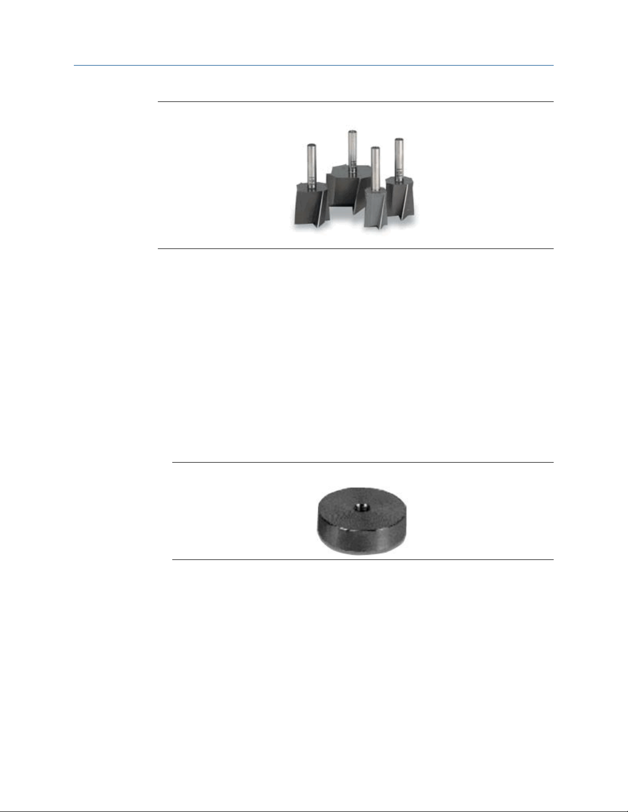
• Spot face or end mill tool
The spot face tool attaches to a standard electric drill and provides a machined surface
that is at least 1.1 times greater than the diameter of the sensor. The spot face tool also
drills a pilot hole that can then be tapped for a stud mounted sensor.
You can purchase the spot face tool from Emerson (MHM P/N 88101), or you can
substitute a spot face tool with similar characteristics as required. Contact your local sales
representative for assistance.
MHM-97927-PBF, Rev 1 43
Installation
August 2020 MHM-97927-PBF
Figure 3-1: Spot face or end mill tool
Attachment tools and supplies
• 1/4-28" taps and tap handle
• 9/16" open-end wrench
• 1/8" hex Allen key
• 3/16" ball-end hex wrench
User Guide
• Wire brush
• Plant-approved cleaner/degreaser
• Plant-approved semi-permanent thread locker (e.g. Loctite)
For epoxy mount, you also need the following:
• 2-part epoxy
• A212 Mounting Pads
Figure 3-2: A212 mounting pad
• (Optional) Grinder – to create a sufficiently flat mounting surface
For motor fin mount, you also need the following:
• Motor Fin Mount Probe
• Epoxy
3.3 Mounting mechanisms
The device may be mounted using any of the mechanisms listed below. Stud mounting is
preferred. The mounts are listed according to our recommendation. Temporary mounting
should be a last resort.
• Stud mounting (preferred)
44 MHM-97927-PBF, Rev 1

User Guide
MHM-97927-PBF August 2020
• Epoxy mounting (alternative)
• Triaxial quick connection
• Motor fin mounting
• Temporary mounting
Installation
3.3.1 Stud mounting (preferred)
Prerequisites
The mounting location must provide a flat surface of at least 1.1 in (27.94mm) in diameter
and a case thickness exceeding 0.4 in. (10.2 mm). If this is not possible, use the epoxy
mount method instead.
Stud mount provides increased reliability, improved frequency response, and increased
signal sensitivity.
CAUTION
Do not exceed the specified torque when tightening a stud-mounted device. Overtightening the device will damage the sensing element and void the manufacturer’s
warranty.
3.3.2
Procedure
1. Prepare the spot face or end mill tool by setting the drill bit depth to a minimum of
0.325 in. (8.255 mm).
2. Using a wire brush and plant-approved cleaner, clean and degrease the surface
area.
3. Keeping the spot face and end mill tool perpendicular to the machine surface, drill
into the mounting location until the surface is smooth to the touch with no
noticeable irregularities. This may require the spot face tool to remove as much as
0.04 in. (1.016 mm) or more from the surface.
Note
If the spot face is not uniform on all sides, it indicates that the spot face tool is not
perpendicular to the mounting surface, and the resulting surface will not allow the
sensor to be mounted properly.
4. Using 1/4-28 in. tap set, tap a pilot hole to a minimum depth of 0.25 in. (6.35 mm).
Epoxy mounting (alternative)
If it is not practical to drill into the machine casing, then the epoxy mount method is
acceptable.
CAUTION
When installing in a hazardous location, all efforts must be made to ensure that the device
is grounded to the machine case.
MHM-97927-PBF, Rev 1 45

Installation
August 2020 MHM-97927-PBF
Procedure
1. If the equipment surface has a radius of curvature that is less than 4 in. (100 mm),
grind a flat surface approximately 0.5 in. (12.7 mm) in diameter.
2. Using a wire brush and plant-approved cleaner, clean and degrease the surface
area.
3. Using a two-part epoxy (such as Emerson P/N A92106)), spray the activator onto
the mounting surface. Place a light coat of epoxy on the surface of the mounting
pad and hold firmly against the machine spot face surface for one minute.
Note
If the adhesive does not set within 1 minute, it indicates that too much epoxy is
applied or that the mounting surface is not prepared properly. Repeat steps 2–3.
4. Ensure that the mounting pad / base of the device is grounded to the machine case.
Use a two-part conductive epoxy (such as Loctite Ablestik 2902) and make a bead
that bridges the mounting pad to the machine case.
5. Use a multimeter to check conductivity between the mounting pad and machine
surface.
User Guide
3.3.3
3.3.4
Triaxial quick connection
Use this mount in scenarios where there is a need to remove the monitor from the
machine but you also need a more permanent type of installation. This mounting
mechanism has two components: the receptacle that attaches to the device and the base
that attaches to the machine. The base itself comes in two options: epoxy mounted, or
stud mounted.
Procedure
1. Find the right location for the base. Make sure that the base notch is oriented with
either the X or the Y axis of the device.
2. Install the device on the receptacle and orientate the whole assembly together.
3. Install the base on the machine using either Stud mounting (preferred) or Epoxy
mounting (alternative).
4. Align the notch on the receptacle with the notch on the base and give it a ¼ turn. It
will lock in the same place every single time.
Motor fin mounting
Procedure
1. Prepare cooling fins on motor for mounting by scraping or grinding any paint or
debris between cooling fins.
2. Clean mounting area with a spray degreaser that will not leave a thin fil lubricating
residue.
3. Mix adhesive.
4. Apply adhesive to the sides and the bottom of the probe portion of the motor fin
mount probe/pad (the area is roughened to enhance the bonding area).
46 MHM-97927-PBF, Rev 1

User Guide
MHM-97927-PBF August 2020
5. Place the motor fin mount probe/pad between the motor fins at the location
desired.
• Correct motor fin mount selection is important. The probe must fit in between
the motor fins, and the bottom of the probe must contact the motor casing.
• For motors that have a space greater than ½” between each fin, motor fin
mount probe pads with a thickness of ½” are available and will reduce the
amount of adhesive needed.
6. Firmly press the motor fin mount probe/pad into place, ensuring the bottom of the
motor fin mount probe/pad is touching the motor casing (this contact area is where
the vibration is transferred from the motor to the sensor).
• The tip of the motor fin mount probe/pad should be as flat against the motor
casing as possible.
• The motor fin mount probe/pad should not be resting on the top of the fins – if it
does, then the bottom of the probe may not be in direct contact with the motor
casing.
7. Use a spatula to redirect any epoxy that has been displaced from the mounting area
when pushing the fin mount probe/pad into place.
8. Fill in any remaining voids with the adhesive to ensure the motor fin mount will be
fixed in place.
9. Allow full cure for the adhesive prior to installing sensor.
Installation
3.3.5
Temporary mounting
Temporary mounting may be required to perform field testing. This allows for testing the
location and orientation of each sensor to get the best possible coverage. A magnetic
mount is the best solution in this case. Once the optimum location is determined, the
device shall be permanently mounted using one of the methods outlined above.
CAUTION
The recommended magnets have a pull force of 40lb-60lb and are very strong. Handle
with care when working with multiple units or near metal structures.
Procedure
1. Prepare the surface. Use a rag or wire brush to remove any loose debris, grease, dirt,
or rust.
2. Attach the device on the magnetic base with a ¼”-28 threaded hole.
3. Position the magnetic base on a ferrous surface, making sure that the device is
properly oriented.
4. Check to see that the device is properly and firmly attached. Wriggle the device
with your hand. It should not wobble or rotate.
MHM-97927-PBF, Rev 1 47

Installation
August 2020 MHM-97927-PBF
User Guide
3.4 Mount the device
Prerequisites
Prepare the surface according to your mounting method. The mounting location is the
machine surface when using stud mount and the mounting pad when using epoxy mount.
The mounting location should be prepared according to best practices.
Procedure
1. To stud mount the device (recommended), prepare the machine surface using a
spot face tool. Then drill and tap a ¼-28” hole 0.25” (6.35mm) deep. Alternately, a
mounting pad with ¼-28” thread can be glued in place using epoxy.
2. With the cover still on the device, use your hand to loosely screw the device into the
threaded hole. Do not tighten.
3. Using your hand, loosely screw device into the mounting location.
4. Remove the cover and battery.
5. Set the device in the proper orientation. Insert a small screwdriver through the
guide hole in the base of the unit (shown below) and use this to hold the device in
the desired orientation.
Make sure that your planes are in the right direction. The Z plane should be vertical.
The orientation of the X and Y axis depends on how you configured your device.
To make sure that your X and Y axis stay where they are, use an allen wrench or a
small screwdriver while you torque down the device to make sure that everything
stays in the correct position. You can also hold the device while you torque it down.
6. While maintaining the device orientation, use a 3/16” ball driver to tighten the
captive screw in the center of the base (shown above) to 2-5 ft-lb.
The mounting screw must be tightened firmly but carefully to prevent stripping out
the mounting thread, typically 1/8 turn past finger tight for steel and slightly less for
aluminum or brass. For high-frequency applications above 7kHz and all PeakVue
48 MHM-97927-PBF, Rev 1

User Guide Installation
MHM-97927-PBF August 2020
measurements, a good quality silicon grease (Dow #4) should be used as a coupling
agent on the mounting ring on the bottom of the device. Only a small amount is
needed.
7. Insert and connect the battery.
8. Mount the cover and then tighten it. Tighten the cover all the way down until the
bottom of the cover touches the base.
Ensure that the base does not turn while tightening the cover. Turning of the base
causes misalignment of the measuring directions.
Always ensure a proper seal when screwing the cover. The cover should be
tightened all the way down to the base to keep the device watertight and free from
the elements.
3.5 Change the battery
The battery that comes with the device is replaceable. The battery may last without need
of replacement or recharge for a minimum of 3 years up to 5 years, if used at room
temperature while collecting and reporting with default collection parameters.
Note
While the device is approved for battery replacement in hazardous locations, always check
with your local Safety Officer before replacing the battery in a hazardous location.
Procedure
1. Using an allen wrench, hold the metal base.
2. Unscrew the device cover and then remove it.
3. Release the holding latch, and then carefully pull the battery tab to take the battery
out of the compartment.
4. Use your finger to release the bottom latch on the battery connect by lifting the tab
and then gently pull it until the connector is released.
5. Plug the battery wire into the connector and position the wire so that it is held by
the battery clamp.
6. Place the battery into the compartment.
7. Snap the battery clamp back into place to secure the battery and wire.
8. Mount the cover and then tighten it. Tighten the cover all the way down until the
bottom of the cover touches the base.
Ensure that the base does not turn while tightening the cover. Turning of the base
causes misalignment of the measuring directions.
Always ensure a proper seal when screwing the cover. The cover should be
tightened all the way down to the base to keep the device watertight and free from
the elements.
MHM-97927-PBF, Rev 1 49

Installation User Guide
August 2020 MHM-97927-PBF
50 MHM-97927-PBF, Rev 1

User Guide Operation
MHM-97927-PBF August 2020
4 Operation
4.1 Verify the device is operational
You can verify the device operates properly using the following methods:
• Field Communicator
• Emerson Wireless Gateway web interface
4.2 Verify operation with Emerson Wireless Gateway
If the device is configured with the Network ID and Join Key, and sufficient time for
network polling has passed, the monitor will be connected to the network.
Note
The time to join a new device to the network is dependent upon the number of devices
being joined and the number of devices in the current network. For one device joining an
existing network with multiple devices, it may take up to five minutes. It may take up to 60
minutes for multiple new devices to join the existing network.
Procedure
1. From the Emerson Wireless Gateway Home page, navigate to the Devices page.
The Devices page shows if the device has joined the network and if it is
communicating properly. It also displays the transmitter tag name, PV, SV, TV, QV,
time of last update. A checkmark in a green box means that the device is working
properly. A red indicator means there is a problem with either the device or its
communication path.
Note
It is normal for the AMS Wireless Vibration Monitor to have a red “X”, on the screen
until the sensor is installed and configured.
Figure 4-1: Emerson Wireless Gateway Devices page
MHM-97927-PBF, Rev 1 51

Operation User Guide
August 2020 MHM-97927-PBF
2. On the Devices page, click + beside a tag name to display more information about
the device.
3. Verify the Network ID and Join Key in the device match those found on the Emerson
Wireless Gateway:
a. From the Emerson Wireless Gateway, click System Settings → Network →
Network Settings.
b. Verify Show join key has a check mark.
Note
The most common cause of incorrect operation is that the Network ID or Join Key
are not set correctly in the device.
4.3 Verify operation with AMS Trex Communicator
You can verify the status of the AMS Wireless Vibration Monitor and configure it using an
AMS Trex Communicator. For instructions on using the AMS Trex unit, see the User Guide.
Note
HART Wireless transmitter communication requires a AMS Wireless Vibration Monitor
Device Descriptor file (DD). Refer to the Field Communicator User's Manual for more
details on DDs or go to http://www2.emersonprocess.com/en-US/brands/Field-
Communicator/Pages/SysSoftDDs.aspxhttps://www.emerson.com/en-us/catalog/amstrex-device-communicator for instructions on adding a DD for AMS Wireless Vibration
Monitor.
Table 4-1: Field Communicator menu
Menu Submenu
Guided Setup Configure Variable Mapping
Configure Device Variable Units
Configure Alert Limits
Configure Acquisition Settings
Join Device to Network
Configure Update Rate
Manual Setup Wireless
Machine
Z Axis
X-Y Axis
Interval Bands
General
Mapping
Device Information
License
52 MHM-97927-PBF, Rev 1

User Guide Operation
MHM-97927-PBF August 2020
Table 4-1: Field Communicator menu
Menu Submenu
Alert Setup Z Axis
Note
Disconnect the leads when you are finished configuring or troubleshooting. The AMS
Wireless Vibration Monitor does not publish any new vibration data to the gateway while
connected to an AMS Trex Device Communicator or HART modem. It can take up to three
minutes for the leads connection to time out; after which, the AMS Wireless Vibration
Monitor resumes reporting new readings to the gateway.
4.4 Check device status
You can check the device status from the AMS Device Manager or the AMS Trex
Communicator.
(continued)
X-Y Axis
Temperature
Battery
IB1-2 (Velocity)
IB3-4 (Accel)
Machine Conditions (PVP)
The images below show the status of the device and what it means.
The device status is dependent upon individual device variable evaluation, system activity,
and operating parameters.
The out-of-the box overall status should always be Good.
The highest level severity is always be asserted, even if there are underlying lower level
alerts.
MHM-97927-PBF, Rev 1 53

Operation User Guide
August 2020 MHM-97927-PBF
4.5 Device variable ranges
The device variables have the following ranges:
1. Saturated – Indicates the saturation point of the transducer. In this device, this
level is not settable by the end user. When this range is violated, the device variable
status is Bad. This is referred to as “Upper Saturated” and “Lower Saturated”.
2. Sensor – Indicates the sensor point of the transducer. In this device, this level is not
settable by the end user. When this range is violated, the device variable status is
Degraded. This is referred to as “Upper Sensor” and “Lower Sensor”.
3. Range – Indicates the user-defined process range. This is referred to as “Upper
Range” and “Lower Range”.
4. Fail – The user-defined fail level(s)
5. Maint – The user-defined maintenance levels.
6. Advise – The user-defined fail levels.
4.6 Device operating limits
Table 4-2: Operational ranges
Sensor Range Frequency Response
Vibration Overall X 16 g's 1 KHz
Vibration Overall Y 16 g's 1 KHz
Vibration Overall Z 80 g's 20 KHz
PeakVue Z 80 g's 20 KHz
Temperature -40⁰C to 85⁰C N/A
4.7 Clean the device
Use a soft towel or paper towel to wipe any excess grime.
If necessary, use a cloth dampened with a mixture of water and mild detergent (similar to
cleaning household dishes).
Do not use solvents to clean the device.
54 MHM-97927-PBF, Rev 1

User Guide Overall Velocity, PeakVue, and temperature
MHM-97927-PBF August 2020
5 Overall Velocity, PeakVue, and
temperature
5.1 Overall Velocity
The Overall Velocity measurement provides a summation of the low-frequency vibration
energy, which indicates fault conditions such as imbalance, misalignment, looseness, and
late-stage bearing problems.
The AMS Wireless Vibration Monitor uses (lower-frequency) Overall Velocity in
conjunction with (higher-frequency) PeakVue to provide a holistic solution across all
frequencies while optimizing the usage of the limited power and bandwidth available in a
wireless device. The majority of developing fault conditions manifest in one or both of
these key parameters.
The difference between the standard vibration waveform and the associated PeakVue
waveform is shown in Figure 5-1 and Figure 5-2. Overall Vibration indicates energy from
shaft rotation, expressed in units of RMS velocity per the ISO 10816 standard. PeakVue, on
the other hand, filters out the rotational energy to focus on impacting. Impacting is
expressed in units of Peak acceleration. This indicates key mechanical problems such as
rolling element bearing faults, gear defects, and under-lubrication.
Figure 5-1: Velocity waveform
MHM-97927-PBF, Rev 1 55

Overall Velocity, PeakVue, and temperature User Guide
August 2020 MHM-97927-PBF
Figure 5-2: PeakVue waveform
While PeakVue is very useful for providing an early indication of impact-related faults in
rolling-element bearings, there are many general applications where a lower-frequency
measurement is more appropriate. Also, virtually all vibration analysts are very familiar
with the Overall Velocity measurement and use it as part of their existing vibration
programs. While it may not be possible to obtain a measurement result comparable to the
PeakVue value reported by the AMS Wireless Vibration Monitor with a non-Emerson unit,
the Overall Velocity measurement is common throughout the industry and should be easy
to correlate with results from handheld instruments.
There are, however, a number of different methods for measuring and reporting Overall
Velocity, so ensure that the measurement conditions are similar when trying to duplicate
the value reported by the AMS Wireless Vibration Monitor with a handheld. The AMS
Wireless Vibration Monitor uses ISO 10816, which defines a measurement bandwidth of 2
Hz to 1 kHz. The ISO 10816 general fault levels at various turning speeds are shown in
Figure 5-3.
56 MHM-97927-PBF, Rev 1

User Guide Overall Velocity, PeakVue, and temperature
MHM-97927-PBF August 2020
Figure 5-3: General fault levels
Depending on the type of machine being monitored, the values shown in this graph
should be multiplied by the service factors given in Table 5-1.
Table 5-1: Service factor multiplier
Machinery type Service factor
Single-stage Centrifugal Pump, Electric Motors, Fans 1.0
Non-critical Chemical Processing Equipment 1.0
Turbine, Turbine Generator, Centrifugal Compressor 1.6
Miscellaneous Equipment 2.0
Figure 5-3 shows the Overall Velocity thresholds for root-mean-square (RMS) velocity in
units of inches per second. Particularly, in digital acquisition systems, it is customary to
measure and calculate with RMS quantities. While it is accepted practice in the industry to
convert between RMS and peak values using the 1.4142 conversion factor, it is not
technically correct to do so except for a pure sinusoidal waveform. For this reason, the
AMS Wireless Vibration Monitor measures, calculates, and reports Overall Velocity in RMS,
and it is necessary to multiply by 1.4142 to get the corresponding peak levels if this is the
preferred format.
Table 5-2: Default velocity levels in AMS Wireless Vibration Monitor
Alert level Velocity (in RMS)
Advise 0.14 in/s
MHM-97927-PBF, Rev 1 57

Overall Velocity, PeakVue, and temperature User Guide
August 2020 MHM-97927-PBF
Table 5-2: Default velocity levels in AMS Wireless Vibration Monitor
Alert level Velocity (in RMS)
Maintenance 0.35 in/s
Failed 1.0 in/s
5.2 PeakVue
™
PeakVue
frequency phenomena associated with developing faults, especially in rolling-element
bearings.
The premise for PeakVue is that the high-frequency components are not readily detected
with more conventional measurements such as Overall Velocity, low-frequency energy
(LFE), or digital overall. This is because the low-frequency measurements either average
the energy or provide an energy summation over a relatively large frequency band, and
the relative amount of energy that is typically contributed by the high-frequency
components is quite small. As a result, even large "spikes" are difficult to detect with classic
techniques.
The difference in the vibration waveform and the associated measurement for overall
vibration versus PeakVue is shown in Figure 5-5 and Figure 5-6. The overall vibration is well
below the established advisory and maintenance alert levels indicating that the machine is
running well. In contrast, the PeakVue graph shows that the values have increased from
zero, and that they are already crossing the advisory alert level and approaching the
maintenance alert level. This early warning about impending defects is key to maintaining
good machine health.
is a patented Emerson technology that is very useful for isolating high-
(continued)
The PeakVue algorithm isolates the peak energy of interest to provide early indications of
developing bearing faults such as inner and outer race defects, ball defects, and
lubrication problems. Any type of "impacting" fault, where metal is contacting metal, is
readily visible with PeakVue long before there is any significant increase in Overall
Vibration. PeakVue is especially useful for monitoring rolling-element bearings.
Figure 5-4 shows an example of a typical formula for calculating the advisory alert level for
PeakVue.
Figure 5-4: PeakVue advisory levels
58 MHM-97927-PBF, Rev 1

User Guide Overall Velocity, PeakVue, and temperature
MHM-97927-PBF August 2020
These are the equations that govern this curve:
These, however, are generic limits. They are provided as a starting point and these values
(for a 3600 RPM machine) are used as the default alert thresholds by the vibration
transmitter.
These levels were devised for periodic data collection with a portable vibration analyzer
and are set relatively low. For frequent automated monitoring, such as that offered by the
AMS Wireless Vibration Monitor, the levels can be increased for most balance of plant
equipment running between 900 and 4000 RPM. You can use the "rule of tens" as a simple
but effective approach to monitoring PeakVue on most rolling element bearing machines.
Using this guideline, we can assume the following:
Level Interpretation
0 Machine is in good condition
10 Some problem is developing on the machine
20 The problem has become serious
40 Problem is critical
Note
The appropriate alerts for a given machine will be a function of its design, service, and
turning speed.
Utilizing the embedded PeakVue technology, the AMS Wireless Vibration Monitor
identified developing problems at a couple of test sites during early field trials. In both
cases, the problem was not visible with conventional low-frequency analysis. The following
examples provide sample data from one of the sites. Notice in the example that the
velocity measurement is indicating less than 0.1 in/s. The PeakVue trend, however,
indicates high-frequency vibration that is regularly in excess of 6 g's.
MHM-97927-PBF, Rev 1 59

Overall Velocity, PeakVue, and temperature User Guide
August 2020 MHM-97927-PBF
Figure 5-5: Example 1: 4600 HP fan motor - OH (Overall)
Figure 5-6: Example 2: 4600 fan motor - OH (PeakVue)
The defective bearing was removed and Figure 5-7 shows the developing problem that
was the source of the impacting. After replacing the bearing, the PeakVue vibration is
significantly reduced, as shown in Figure 5-8, indicating that the problem has been
resolved.
60 MHM-97927-PBF, Rev 1

User Guide Overall Velocity, PeakVue, and temperature
MHM-97927-PBF August 2020
Figure 5-7: Defective bearing
MHM-97927-PBF, Rev 1 61

Overall Velocity, PeakVue, and temperature User Guide
August 2020 MHM-97927-PBF
Figure 5-8: Motor - OH after the bearing is replaced (PeakVue)
5.3 Temperature
The levels at which to set temperature alerts depend on a number of factors including the
specific process, the operating environment, and the characteristics of the equipment
being monitored. This section provides some generic guidelines, given some knowledge
of the variables involved, for setting the thresholds for your specific AMS Wireless
Vibration Monitor installation. However, the generic methodologies described here are no
substitute for first-hand knowledge of your plant. If, for example, you know that you have
problems when a temperature exceeds a particular value, then set your thresholds
accordingly rather than following these generic guidelines.
In general, the best way to detect a developing fault related to temperature is to look for
an increase in temperature, relative to ambient, over time. This implies that, for reliable
alerting, the thresholds should change as ambient temperature changes. In practice, this
can be difficult to do because it requires the operator to constantly monitor the ambient
temperature and adjust the alert levels accordingly. It is customary, therefore, to pick an
"average" ambient temperature (that is generally seasonal for outdoor installations) and
choose fixed thresholds based on this average. Also, there are issues with this
methodology (such that it does not work well) in areas with large variations in ambient
temperature.
You can select thresholds based on some absolute temperature limit. In practice, this is
much easier to maintain but is not as effective at detecting early failures as relative
monitoring.
62 MHM-97927-PBF, Rev 1

User Guide Overall Velocity, PeakVue, and temperature
MHM-97927-PBF August 2020
5.3.1 Relative temperature monitoring
The recommended generic guidelines for setting the thresholds based on the relative
change are:
T
= 10°C increase
Advise
T
Maintenance
T
Failed
Assuming that the ambient temperature is 25°C, when operating at steady-state, you have
determined that the normal temperature at this point on your equipment is 55°C. Your
"baseline" relative difference is 30°C. Using these guidelines, you should choose the Advise,
Maintenance, and Failed levels for a difference of 40°C, 45°C, and 50°C, respectively.
Assuming the ambient temperature is constant at 25°C, this means the thresholds
become 65°C, 70°C, and 75°C for Advise, Maintenance, and Failed, respectively. Then, as
the ambient temperature changes, the thresholds should be changed accordingly (e.g., a
5°C increase in ambient temperature raises the alert thresholds by 5°C).
= 15°C increase
= 20°C increase
5.3.2
Absolute temperature monitoring
For monitoring a driven component (such as a pump or fan), there are no generic rules to
determine the default levels without some prior knowledge of the steady-state baseline
(good) value. In general, the Advise level should be set about 10°C to 20°C above this
baseline, with the Maintenance level about 10°C above Advise and the Failed level about
10°C above Maintenance.
There are equations that define the suggested generic thresholds for monitoring motor
(driver) temperature. These are based on characteristics of the motor as well as
knowledge of the ambient temperature.
The first step is to determine the estimated winding temperature, which is dependent on
the following variables:
• Insulation type
• Motor type
• Ambient temperature
• Altitude
The estimated winding temperature, TW, is the rise in temperature, T
appropriate type of motor adjusted for high ambient temperature (Ta) effects.
T
=
rise
• 65°C + serv_fact_temp; for class A insulation
, for the
rise
• 85°C + serv_fact_temp; for class B insulation
• 110°C + serv_fact_temp; for class F insulation
• 130°C + serv_fact_temp; for class H insulation
• 150°C + serv_fact_temp; for class N insulation
where serv_fact_temp =
MHM-97927-PBF, Rev 1 63

Overall Velocity, PeakVue, and temperature User Guide
August 2020 MHM-97927-PBF
• 5 for service factor of 1.15 or greater
• -5 for either open or totally enclosed fan cooled (TEFC) motors, and service factor of
1.0
• 0 for either totally enclosed non-ventilated (TENV) motors or motors with
encapsulated windings, and service factor of 1.0
If elevation > 3300 ft (1000m), then:
T
= T
rise
{1-[(altitude (units of ft) - 3300)/33,000]}
rise
If Ta is less than or equal to 40°C (or unknown), then:
Tw = T
rise
+ 40°C
If Ta > 40°C, then:
Tw = T
+ 40°C - (Ta - 40°C)
rise
If Ta is unavailable, assume that Ta is less than 40°C.
Next, calculate the generic alert thresholds based on the estimated winding temperature,
TW.
T
= Fault level alarm temperature (°C) of the motor skin (frame)
f_fault
T
f_maintenance
T
f_advisory
= Maintenance level alarm temperature (°C) of the motor skin
= Advisory level alarm temperature (°C) of the motor skin
Alarm levels
For open drip proof (ODP) motors:
T
= 35.5366*Ln(Tw) - 91.1571
f_fault
For totally enclosed motors:
T
= 37.2028*Ln(Tw) - 102.8868
f_fault
For all motors:
T
f_maintenance
T
f_advisory
= T
= T
f_fault
f_fault
- 20°C
- 10°C
Error indication and steady-state determination
• Do not use any data readings collected within 30 seconds of motor start up.
• Steady-state is said to have been reached when, over any 5-minute time interval, the
maximum variation in temperature is less than 2°F.
64 MHM-97927-PBF, Rev 1

User Guide Specifications and reference data
MHM-97927-PBF August 2020
A Specifications and reference data
A.1 Functional specifications
Input
Output
Humidity limits
Transmit rate
Measurement Measurement Parameters
Three internal MEMS accelometers oriented in the X-Y-Z direction. The Z
accelometer has the greatest bandwidth and is considered the primary sensor.
The device also has a temperature sensor designed to read the temperature
near the mounting point.
Wireless-enabled, linear with temperature or input.
0–95% relative humidity
User-selectable, 60 seconds to 24 hours.
The device is capable of measuring and reporting machine health
measurement parameters and generating alerts based on overall vibration in
each axis as well as peak impact measurements in the primary axis and
temperature readings.
Measurement precision
Measurement precision refers to the variability of the same measurement in a
fixed operating environment under steady-state conditions. For vibration, this
value is obtained with statistical measurements with 1 g-peak (9.81 m/s2)
input excitation at a frequency of 100 Hz. For temperature, this value is
obtained with statistical measurements at room temperature.
• Vibration: 0.2 dB
• Temperature: +/- 2°C
Amplitude Range
Primary axis: +/- 80 g's
Secondary axis: +/- 16g's
Measurement Accuracy
+/- 3 dB from 2 Hz to 10 kHz primary axis, +/- 3 dB from 2 Hz to 1 kHz
secondary axis
Dynamic signal range
Target: 80dB
MHM-97927-PBF, Rev 1 65

Specifications and reference data User Guide
August 2020 MHM-97927-PBF
A.2 Physical specifications
Battery
Table A-1: Tadiran Lithium Batteries Model TL-4920/VE
Nominal capacity @ 3 mA, to 2 V 8.5 Ah
Rated voltage 3.6 V
Maximum recommended continuous current 75 mA
Maximum 1 sec. pulse capability 200 mA
Weight 49.5 g (1.746 oz)
Volume 26 cc
Operating temperature range -55 ºC to +85 ºC
U.L. Component Recognition, MH 12193
Field Communicator connections
• HART ports
• Clips attached to the HART ports
Mounting
Mounting tools and supplies depend on the mounting mechanism. For more information,
see Mounting tools and supplies.
Mounting screw thread is 1/4 - 28
Weight
0.697 lb (315 g)
Enclosure ratings
Housing is NEMA 4X and IP66
A.3 Performance specifications
Temperature Limits
The device is rated for operation in the range from -40 to +85C.
Table A-2: Temperature limits
Device Operating limit Storage limit
-55 to +85C
AMS Wireless Vibration
Monitor
66 MHM-97927-PBF, Rev 1
-40 to +85C
Prolonged storage above +75 C
Note
degrades battery life

User Guide Specifications and reference data
MHM-97927-PBF August 2020
A.4 Radio specifications
Parameter Value
Frequency Band 2.4GHz - 2.4835GHz
Output Power +8dBm
Receiver Sensitivity -93dBm
Range 100m (outdoor +25 C, 50% RH)
A.5 Device variable alert limits
This table shows the alert limits of the device variables.
Table A-3: X Overall
Axis Severity Upper Limit Lower limit Unit Notes
X Overall Saturated 70 0 in/s Read-only
X Overall Sensor 70 0 in/s Read-only
X Overall Range 5 0 in/s Can be set by the user up to
the sensor range
X Overall Fail 1 Not
Applicable
X Overall Maint 0.35 Not
Applicable
X Overall Advise 0.14 Not
Applicable
in/s
in/s
in/s
Table A-4: Y Overall
Axis Severity Upper Limit Lower Limit Unit Notes
Y Overall Saturated 70 0 in/s Read-only
Y Overall Sensor 70 0 in/s Read-only
Y Overall Range 5 0 in/s Can be set by
the user up to
the sensor
range
Y Overall Fail 1 0 in/s
Y Overall Maint 0.35 0 in/s
Y Overall Advise 0.14 0 in/s
Table A-5: Z Overall
Axis Severity Upper Limit Lower Limit Units Notes
Z Overall Saturated 70 0 in/s Read-only
MHM-97927-PBF, Rev 1 67

Specifications and reference data User Guide
August 2020 MHM-97927-PBF
Table A-5: Z Overall
Axis Severity Upper Limit Lower Limit Units Notes
Z Overall Sensor 70 0 in/s Read-only
Z Overall Range 5 0 in/s Can be set by
Z Overall Fail 1 0 in/s
Z Overall Maint 0.35 0 in/s
Z Overall Advise 0.14 0 in/s
(continued)
the user up to
the sensor
range
Table A-6: Z Peakvue
Axis Severity Upper Limit Lower Limit Units Notes
Z Peakvue Error Not Applicable Not Applicable 250 Read-only
Z Peakvue Unused Not Applicable Not Applicable 250 Read-only
Z Peakvue Saturated 100 0 g Can be set by
the user up to
the sensor
range
Z Peakvue Sensor 100 0 g
Z Peakvue Range 100 0 g
Z Peakvue Fail 40 0 g
Z Peakvue Maint 20 0 g
Z Peakvue Advise 10 0 g
Table A-7: IB1 Velocity
Axis Severity Upper Limit Lower Limit Units Notes
IB1 Velocity Unused Not Applicable Not Applicable 250 Read-only
IB1 Velocity Saturated 70 0 in/s Read-only
IB1 Velocity Sensor 70 0 in/s Can be set by
the user up to
the sensor
range
IB1 Velocity Range 5 0 in/s
IB1 Velocity Fail 0.6 0 in/s
IB1 Velocity Maint 0.21 0 in/s
IB1 Velocity Advise 0.084 0 in/s
68 MHM-97927-PBF, Rev 1

User Guide Specifications and reference data
MHM-97927-PBF August 2020
Table A-8: IB2 Velocity
Axis Severity Upper Limit Lower Limit Units Notes
IB2 Velocity Saturated 70 0 in/s Read-only
IB2 Velocity Sensor 70 0 in/s Read-only
IB2 Velocity Range 5 0 in/s Can be set by
the user up to
the sensor
range
IB2 Velocity Fail 0.3 0 in/s
IB2 Velocity Maint 0.105 0 in/s
IB2 Velocity Advise 0.042 0 in/s
Table A-9: IB3 Accel
Axis Severity Upper Limit Lower Limit Units Notes
IB3 Accel Saturated 100 0 g Read-only
IB3 Accel Sensor 100 0 g Read-only
IB3 Accel Range 50 0 g Can be set by
the user up to
the sensor
range
IB3 Accel Fail 10 0 g
IB3 Accel Maint 7 0 g
IB3 Accel 4 0 g
Table A-10: IB4 Accel
Axis Severity Upper Limit Lower Limit Units Notes
IB4 Accel Saturated 100 0 g Read-only
IB4 Accel Sensor 100 0 g Read-only
IB4 Accel Range 50 0 g Can be set by
the user up to
the sensor
range
IB4 Accel Fail 15 0 g
IB4 Accel Maint 10 0 g
IB4 Accel Advise 6 0 g
Table A-11: Machine Temperature
Axis Severity Upper Limit Lower Limit Units Notes
Machine
Temperature
MHM-97927-PBF, Rev 1 69
Saturated 95 -50 °C Read-only

Specifications and reference data User Guide
August 2020 MHM-97927-PBF
Table A-11: Machine Temperature
Axis Severity Upper Limit Lower Limit Units Notes
Machine
Temperature
Machine
Temperature
Machine Temp Fail 75 -40 °C
Machine
Temperature
Machine
Temperature
Sensor 95 -50 °C Read-only
Range 95 -50 °C Can be set by
Maint 70 -35 °C
Advise 65 -30 °C
(continued)
the user up to
the sensor
range
Table A-12: Supply Voltage
Axis Severity Upper Limit Lower Limit Units Notes
Supply
Voltage
Supply
Voltage
Saturated 3.75 0 V Read-only
Sensor 3.75 0 V Read-only
Supply
Voltage
Supply
Voltage
Supply
Voltage
Supply
Voltage
Range 3.7 2.3 V Read-only
Fail Not Applicable 2.7 V Read-only
Maint Not Applicable 2.85 V
Advise Not Applicable 3 V
Table A-13: Speed
Axis Severity Upper Limit Lower Limit Units Notes
Speed Saturated 10000 0 rpm Limits
calculated by
device and not
user settable.
Speed Sensor 10000 0 rpm Limits
calculated by
device and not
user settable.
Speed Range 3000 0 rpm Limits
calculated by
device and not
user settable.
70 MHM-97927-PBF, Rev 1

User Guide Specifications and reference data
MHM-97927-PBF August 2020
Table A-13: Speed
Axis Severity Upper Limit Lower Limit Units Notes
Speed Fail Not Applicable Not Applicable rpm Limits
Speed Maint Not Applicable Not Applicable rpm Limits
Speed Advise 2000 1600 rpm Limits
Mechanical
Condition
(continued)
calculated by
device and not
user settable.
calculated by
device and not
user settable.
calculated by
device and not
user settable.
Saturated 1000 0 None Limits
calculated by
device and not
user settable.
Table A-14: Mechanical Condition
Axis Severity Upper Limit Lower Limit Units Notes
Mechanical
Condition
Sensor 1000 0 None Limits
constant in the
device and not
user-settable.
Mechanical
Condition
Mechanical
Condition
Mechanical
Condition
Mechanical
Condition
Range 100 0 None Limits
constant in the
device and not
user-settable.
Fail 70 0 None Limits
constant in the
device and not
user-settable.
Maint 40 0 None Limits
constant in the
device and not
user-settable.
Advise 10 0 None Limits
constant in the
device and not
user-settable.
MHM-97927-PBF, Rev 1 71

Specifications and reference data User Guide
August 2020 MHM-97927-PBF
Table A-15: Lubrication Condition
Axis Severity Upper Limit Lower Limit Units Notes
Lubrication
Condition
Lubrication
Condition
Lubrication
Condition
Lubrication
Condition
Lubrication
Condition
Lubrication
Condition
Saturated 1000 0 None Limits
constant in the
device and not
user-settable.
Sensor 1000 0 None Limits
constant in the
device and not
user-settable.
Range 100 0 None Limits
constant in the
device and not
user-settable.
Fail 70 0 None Limits
constant in the
device and not
user-settable.
Maint 40 0 None Limits
constant in the
device and not
user-settable.
Advise 10 0 None Limits
constant in the
device and not
user-settable.
72 MHM-97927-PBF, Rev 1

User Guide Product certifications
MHM-97927-PBF August 2020
B Product certifications
Note
For specific device certifications, always refer to the product nameplate and markings on
the device.
B.1 Approved manufacturing locations
Emerson
835 Innovation Drive
Knoxville, TN 37932 USA
T: +1 865-675-2400
Benchmark Electronics (Thailand) Plc.
109 moo.4, Chaimongkol, Muang, Nakorn Ratchasima
Thailand 30000
T: +66 44-233-800
B.2 Wireless certifications
Telecommunications compliance
All wireless devices require certification to ensure that they adhere to regulations
regarding the use of the RF spectrum. Nearly every country requires this type of product
certification. Emerson works with governmental agencies around the world to supply fully
compliant products and remove the risk of violating country directives or laws governing
wireless device usage.
Radio Equipment Directive (2014/53/EU)
Emerson complies with the Radio and Equipment Directive.
FCC approvals
This equipment has been tested and found to comply with the limits for a Class B digital
device, pursuant to part 15 of the FCC rules. These limits are designed to provide
reasonable protection against harmful interference in a residential installation. This
equipment generates, uses and can radiate radio frequency energy and, if not installed
and used in accordance with the instructions, may cause harmful interference to radio
communications. However, there is no guarantee that interference will not occur in a
particular installation. If this equipment does cause harmful interference to a radio or
television reception, which can be determined by turning the equipment off and on, the
user is encouraged to try to correct the interference by one or more of the following
measures:
• Reorient or relocate the receiving antenna.
• Increase the separation between the equipment and receiver.
• Connect the equipment into an outlet on a circuit different from that to which the
receiver is connected.
MHM-97927-PBF, Rev 1 73
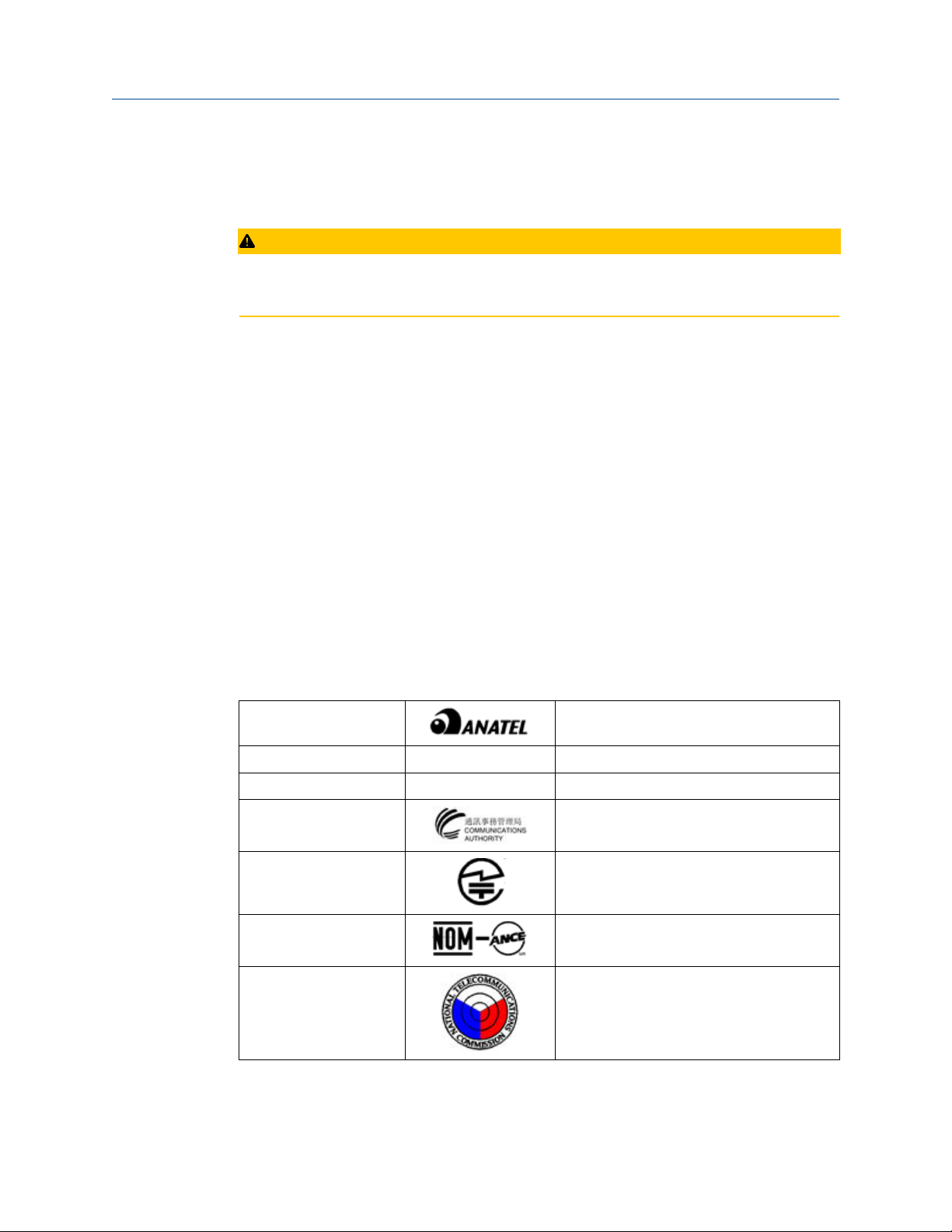
Product certifications User Guide
August 2020 MHM-97927-PBF
• Consult the dealer or an experienced radio/TV technician for help.
• This device must be installed to ensure a minimum antenna separation distance of
20cm from all persons.
CAUTION
Changes or modification not expressly approved by the party responsible for compliance
could void the user's authority to operate the equipment.
ISED approvals
This device contains license-exempt transmitter(s)/receiver(s) that comply with
Innovation, Science and Economic Development Canada’s license-exempt RSS(s).
Operation is subject to the following two conditions:
1. This device may not cause interference.
2. This device must accept any interference, including interference that may cause
undesired operation of the device.
Cet appareil contient des émetteurs / récepteurs exemptés de licence qui sont conformes
aux RSS exempts de licence d'Innovation, Sciences et Développement économique
Canada. Son fonctionnement est soumis aux deux conditions suivantes:
1. Cet appareil ne doit pas provoquer d'interférences.
2. Cet appareil doit accepter toute interférence, y compris les interférences pouvant
entraîner un fonctionnement indésirable de l'appareil.
Radio approvals
Table B-1: Radio Approvals
Brazil Pending
Canada IC: 3434A-A9530M1
Ecuador Pending
Hong Kong Pending
Japan Pending
Mexico Pending
Philippines Pending
74 MHM-97927-PBF, Rev 1

User Guide Product certifications
MHM-97927-PBF August 2020
Table B-1: Radio Approvals
Serbia Pending
Singapore Pending
South Africa Pending
US NL5-A9530M1 Model: A9530V1, A9530V3
Note
The table above does not include all countries for which certificates have been issued. For
a complete list, please contact you local Emerson Sales Representative.
(continued)
B.3 Ordinary location certification (CSA)
As standard, the transmitter has been examined and tested to determine that the design
meets basic electrical, mechanical, and fire protection requirements by CSA, a nationally
recognized testing laboratory (NRTL) as accredited by the Federal Occupational Safety and
Health Administration (OSHA).
Electromagnetic Compatibility (EMC) (2014/30/EU)
All Models: EN 61326-1
Canadian Standards Association (CSA)
CAN/CSA-C22.2 No. 61010-1-04 - Safety Requirements for Electrical Equipment for
Measurement, Control, and Laboratory Use, Part 1: General Requirements
ISA S82.02.01 2nd (IEC 61010-1 Mod) - Safety Standards for Electrical and Electronic Test,
Measuring, Controlling and Related Equipment - General Requirements
UL 61010-1 2nd - Safety Requirements for Electrical Equipment for Measurements,
Control, and Laboratory Use, Part 1: General Requirements
B.4 CE mark
The device has been tested and complies with all relevant directives required for CE
marking.
MHM-97927-PBF, Rev 1 75

Product certifications User Guide
August 2020 MHM-97927-PBF
Country Restriction
Bulgaria General authorization required for outdoor use and public service.
Italy If used outside of own premises, general authorization is required.
Norway May be restricted in the geographical area within a radius of 10 km from
the center of Ny-Alesund.
Romania Use on a secondary basis. Individual license is required.
76 MHM-97927-PBF, Rev 1

User Guide Product certifications
MHM-97927-PBF August 2020
B.5 Hazardous locations certifications
Model No:: A9530
Product Name: Wireless Vibration Monitor
The AMS Wireless Vibration Monitor carries certificates for operation in hazardous
locations.
Table B-2: Hazardous locations certifications
CSA C/US Certificate
CSA20CA80026524
IECEx Certificate IECEx CSA 20.0002X Ex ia IIC T4 Ga
ATEX Certificate CSANe
20ATEX2042X
Class I Division 1 Groups A, B, C, D
Class I Zone 0 AEx / Ex ia IIC T4 Ga
-40ºC ≤ Ta ≤ +85ºC
Type 4X Enclosure
Ta: -40ºC to +85ºC
II 1 G Ex ia IIC T4 Ga
-40ºC ≤ Ta ≤ +85ºC
IP66
Other approvals
For a complete list of approvals, see the product page at http://www.emerson.com/
AMSVibrationMonitor.
Conditions for Safe Use
1. Shall be powered only by C-sized lithium primary cell type TL-4920/VE
manufactured by Tadiran or Emerson Part Number A0702PPU.
2. HART Terminal Entity Parameters:
Uo = 5.84V, Io = 116mA, Po =169mW, Co = 0.1µF, Lo = 5mH;
Ui = 5.27V, Ii = 5mA, Pi = 6.6mW, Ci = 13 µF, Li = 0.022mH
3. The device may be configured using the HART terminals only by 375, 475, or TREX
field communicators.
4. Under certain extreme circumstances, the non-metallic parts incorporated in the
enclosure of this equipment may generate an ignition-capable level of electrostatic
discharge. Therefore, the equipment shall not be installed in a location where the
external conditions are conductive to the build-up of electrostatic charge on such
surfaces. In addition, the equipment shall only be cleaned with a damp cloth.
5. The device shall be installed on an earthed metal frame.
Note
Battery may be replaced in hazardous locations. Only replace battery with Tadiran Part
Number TL-4920/VE or Emerson Part Number A0702PPU.
MHM-97927-PBF, Rev 1 77

Product certifications User Guide
August 2020 MHM-97927-PBF
Note
The markings that appear on the monitor housing determine whether a device is suitable
for operation in a specific hazardous location. This further requires that the monitor is
operated in accordance with the installation drawings provided with the unit.
Conditions d'utilisation sûre:
1. Ne doit être alimenté que par une cellule primaire au lithium de taille C de type
TL-4920/VE fabriquée par Tadiran ou Emerson Part Number A0702PPU.
2. Paramètres d'entité de terminal HART:
Uo = 5.84 V, Io = 116 mA, Po = 169 mW, Co = 0.1 µF, Lo = 5 mH;
Ui = 5.27 V, Ii = 5 mA, Pi = 6.6 mW, Ci = 13 µF, Li = 0.022 mH
3. L'appareil ne peut être configuré à l'aide des terminaux HART que par des
communicateurs de terrain 375, 475 ou TREX.
4. Dans certaines circonstances extrêmes, les pièces non métalliques incorporées dans
le boîtier de cet équipement peuvent générer un niveau de décharge
électrostatique capable d'allumage. Par conséquent, l'équipement ne doit pas être
installé dans un endroit où les conditions externes conduisent à l'accumulation de
charges électrostatiques sur de telles surfaces. De plus, l'équipement ne doit être
nettoyé qu'avec un chiffon humide.
5. L'appareil doit être installé sur un cadre métallique mis à la terre.
Warnings:
1. Care should be taken to protect this device from impact or abrasion if located in a
zone 0 environment.
2. Substitution of components may impair intrinsic safety.
3. The battery may present a potential electrostatic ignition hazard. Use Caution when
replacing the battery.
Avertissements:
1. Des précautions doivent être prises pour le protéger des chocs ou de l'abrasion s'il
est situé dans un environnement de zone 0.
2. La substitution de composants peut compromettre la sécurité intrinsèque.
3. La batterie peut présenter un risque potentiel d'allumage électrostatique. Soyez
prudent lors du remplacement de la batterie.
List of Standards:
IEC:
IEC 60079-0 7th Edition, December 2017
IEC 60079-11 6th Edition, June 2011
ATEX:
EN IEC 60079-0:2018
EN 60079-11:2012
78 MHM-97927-PBF, Rev 1

User Guide Product certifications
MHM-97927-PBF August 2020
North America:
CAN/CSA C22.2 No. 61010-1-12
UL Std. No. 61010-1 3rd Ed.
CAN/CSA C22.2 No. 60079-0 7th Ed.: 2019
UL 60079-0 7th Ed.: 2019
CAN/CSA C22.2 No. 60079-11 6th Ed.: 2014
UL 60079-11: 6th Ed.: 2013
CAN/CSA-C22.2 No. 60529 Ed. 2.2: 2016
ANSI/IEC 60529-2004 (R2011)
CAN/CSA-C22.2 No. 94.2-2007 (R2012)
UL 50E 2015
B.6 Waste Electrical and Electronic Equipment
Marking for the Waste of Electrical and Electronic Equipment in accordance with Article II
(2) of Directive 2012/19/EU (WEEE). The European Directive 2012/19/EU requires
marking:
• That applies to electrical and electronic equipment falling under Annex 1 Category 9 of
Directive 2012/19/EU.
• That serves to clearly identify the producer of the equipment and that the equipment
has been put on the market after 13 August 2005.
• That the crossed out wheeled bin alerts the end-user to dispose this equipment via the
special recycling procedure for electrical and electronic equipment that is applicable in
the country of use.
• The shown marking is attached to the product and identifies the product to fall within
the scope of this directive.
MHM-97927-PBF, Rev 1 79

Product certifications User Guide
August 2020 MHM-97927-PBF
80 MHM-97927-PBF, Rev 1

User Guide Third-party licenses
MHM-97927-PBF August 2020
C Third-party licenses
C.1 Dust SmartMeshSDK C Library
Copyright (c) 2012, Dust Networks
All rights reserved.
Redistribution and use in source and binary forms, with or without modification, are
permitted provided that the following conditions are met:
• Redistributions of source code must retain the above copyright notice, this list of
conditions and the following disclaimer.
• Redistributions in binary form must reproduce the above copyright notice, this list of
conditions and the following disclaimer in the documentation and/or other materials
provided with the distribution.
• Neither the name of Dust Networks nor the names of its contributors may be used to
endorse or promote products derived from this software without specific prior written
permission.
THIS SOFTWARE IS PROVIDED BY THE COPYRIGHT HOLDERS AND CONTRIBUTORS "AS IS"
AND ANY EXPRESS OR IMPLIED WARRANTIES, INCLUDING, BUT NOT LIMITED TO, THE
IMPLIED WARRANTIES OF MERCHANTABILITY AND FITNESS FOR A PARTICULAR PURPOSE
ARE DISCLAIMED. IN NO EVENT SHALL DUST NETWORKS BE LIABLE FOR ANY DIRECT,
INDIRECT, INCIDENTAL, SPECIAL, EXEMPLARY, OR CONSEQUENTIAL DAMAGES
(INCLUDING, BUT NOT LIMITED TO, PROCUREMENT OF SUBSTITUTE GOODS OR SERVICES;
LOSS OF USE, DATA, OR PROFITS; OR BUSINESS INTERRUPTION) HOWEVER CAUSED AND
ON ANY THEORY OF LIABILITY, WHETHER IN CONTRACT, STRICT LIABILITY, OR TORT
(INCLUDING NEGLIGENCE OR OTHERWISE) ARISING IN ANY WAY OUT OF THE USE OF THIS
SOFTWARE, EVEN IF ADVISED OF THE POSSIBILITY OF SUCH DAMAGE.
MHM-97927-PBF, Rev 1 81

Third-party licenses User Guide
August 2020 MHM-97927-PBF
82 MHM-97927-PBF, Rev 1

User Guide
MHM-97927-PBF August 2020
Index
Index
A
absolute temperature monitoring 63
alert levels 40
alert limits, device variables 67
alert thresholds, default 40
alerts 33
ambient temperature 62
AMS Device Manager
Advanced Diagnostics application 22
configure alert limits 23
configure publishing 23
configure sensors 22
configure units 23
Configure window 23
configuring wireless network credentials 20
device revision 22
effective acquisition rate 23
guided setup 23
join device to network 22
manual setup 23
MHM Access Control 22
Overview window 22
restore factory default settings 34
right-click menu 21
sensor power enable 23
Service Tools window 34
spectra 34
trends 34
E
electromagnetic compatibility 66
enclosure rating 66
environmental considerations 7
epoxy mount 45
F
features, monitor 9
field communicator menu tree 37
field communicator, configuration with 37
functional specifications 65
H
hazardous location certificates 77
I
installation 46
installation location 7
L
LCD network status screens 51
M
C
CE marking 75
commissioning 7
configuration defaults, defaults, configuration 38
configuration options 38
configuration with field communicator 37
configuration, alert setup 33
configuration, guided setup 23
configuring wireless network credentials, AMS Device
Manager 20
construction materials, transmitter 66
D
DC power 7
default alert thresholds 40
default configurations 38
device revisions 9
device status 53
device, parts 9
MHM-97927-PBF, Rev 1 83
magnetic mount 47
maintenance 34
manufacturing location 73
minimize power consumption 39
monitor, parts 9
motor fint mount 46
mounting mechanism, quick disconnect 46
mounting tools, sensor 43
O
operating limit, sensors 54
ordinary location certification 75
overall velocity 55
overview 9
overview, monitor 9
P
parameter units 38
parameters, trending 40
PeakVue 58

Index User Guide
August 2020 MHM-97927-PBF
performance specifications 66
physical specifications 66
power consumption 39
powersave mode 39
prepare sensor mount 44
preparing the sensor mount
epoxy mount 45
product support 7
publish rate 39
publishing mode
generic mode 39
optimized mode 39
R
radio specifications, radio 67
relative temperature monitoring 63
restore factory default settings 34
return of materials 7
revisions, device 9
S
safety messages 5
safety, symbols 5
sensor mount, preparing 44
sensor mounting/attachment tools 43
sensor operating limits 54
sensors
mounting tools 43
operating limit 54
setup, alerts 33
setup, AMS Device Manager 23
setup, guided 23
Smart Power Module 7
spectral data 34
stud mount 45
V
variable mappings 14
verifying status and operation 51
W
weight, transmitter 66
wireless certifications 73
T
temperature
absolute monitoring 63
alert thresholds 63
limits 7
relative monitoring 63
temperature limits 7
temporary mount 47
trending of parameters 40
trends 34
U
units 38
update rate 39
84 MHM-97927-PBF, Rev 1

User Guide
MHM-97927-PBF August 2020
MHM-97927-PBF, Rev 1 85

MHM-97927-PBF
Rev. 1
2020
Emerson
835 Innovation Drive
Knoxville, TN 37932 USA
T +1 865-675-2400
F +1 865-218-1401
www.Emerson.com
©
2020, Emerson.
The contents of this publication are presented for informational purposes only, and while every
effort has been made to ensure their accuracy, they are not to be construed as warranties or
guarantees, express or implied, regarding the products or services described herein or their use or
applicability. All sales are governed by our terms and conditions, which are available on request. We
reserve the right to modify or improve the designs or specifications of our products at any time
without notice.
All rights reserved. AMS is a mark of one of the Emerson group of companies. The Emerson logo is a
trademark and service mark of Emerson Electric Co. All other marks are the property of their
respective owners.
 Loading...