


Reference Manual
MHM-97408, Rev 22
September 2020
AMS 9420 Wireless Vibration Transmitter
Reference Manual

Copyright
©
2020 by Emerson. All rights reserved.
No part of this publication may be reproduced, transmitted, transcribed, stored in a retrieval system, or translated into any
language in any form by any means without the written permission of Emerson.
Disclaimer
This manual is provided for informational purposes. EMERSON MAKES NO WARRANTY OF ANY KIND WITH REGARD TO THIS
MATERIAL, INCLUDING, BUT NOT LIMITED TO, THE IMPLIED WARRANTIES OF MERCHANTABILITY AND FITNESS FOR A PARTICULAR
PURPOSE. Emerson shall not be liable for errors, omissions, or inconsistencies that may be contained herein or for incidental or
consequential damages in connection with the furnishing, performance, or use of this material. Information in this document is
subject to change without notice and does not represent a commitment on the part of Emerson. The information in this manual is
not all-inclusive and cannot cover all unique situations.
Patents
The product(s) described in this manual are covered under existing and pending patents.
Where to get help
Software Registration
Phone:
Toll free 888.367.3774, option 2 (U.S. and Canada)
+63.2.702.1111 (Rest of world)
Email:
Web:
wwcs.custserv@emerson.com
http://www.emerson.com/machineryhealthreg
Product Support
Emerson provides a variety of ways to reach your Product Support team to get the answers you need when you need them:
Phone
Toll free 800.833.8314 (U.S. and Canada)
+1.512.832.3774 (Latin America)
+63.2 702.1111 (Asia Pacific, Europe, and Middle East)
Email
Web
ap-sms@emerson.com
http://www.emerson.com/en-us/contact-us
To search for documentation, visit http://www.emerson.com.
To view toll free numbers for specific countries, visit http://www.emerson.com/technicalsupport.
2

Reference Manual Contents
MHM-97408 September 2020
Contents
Chapter 1 Introduction.................................................................................................................. 6
1.1 Safety messages...............................................................................................................................6
1.2 Overview.......................................................................................................................................... 7
1.3 Considerations............................................................................................................................... 11
1.4 Return of materials.........................................................................................................................12
Chapter 2 Install the AMS 9420.....................................................................................................14
2.1 Sensors...........................................................................................................................................14
2.1.1 Sensor operating limits................................................................................................................14
2.1.2 Sensor handling...........................................................................................................................15
2.1.3 Sensor mounting/attachment tools and supplies........................................................................ 16
2.1.4 Prepare the sensor mount........................................................................................................... 17
2.1.5 Attach the sensors.......................................................................................................................18
2.1.6 Secure the sensor cables..............................................................................................................22
2.1.7 Conduit installation guidelines.................................................................................................... 23
2.1.8 Cable entry port installation guidelines........................................................................................24
2.1.9 Attach sensor wiring to the AMS 9420 terminals......................................................................... 27
2.2 Power the AMS 9420 with a power module.....................................................................................30
2.2.1 Power module installation and replacement................................................................................30
2.2.2 Physical installation..................................................................................................................... 32
2.3 Power the AMS 9420 with external DC power.................................................................................33
2.3.1 Emerson A9000P description of intended use..............................................................................33
2.3.2 Optional spacer........................................................................................................................... 33
2.3.3 Connect external DC power to Emerson wireless transmitters.....................................................34
2.3.4 Connect external DC power and ICP® accelerometer inputs to an AMS 9420............................... 36
2.4 Install the end cap.......................................................................................................................... 39
Position the antenna.......................................................................................................................40
2.5
2.6 Liquid Crystal Display (LCD)............................................................................................................ 42
2.6.1 Rotate the LCD............................................................................................................................ 42
2.6.2 Enable the LCD............................................................................................................................ 43
2.6.3 Turn on the LCD...........................................................................................................................44
2.7 Ground the transmitter.................................................................................................................. 45
Chapter 3 Configure the AMS 9420...............................................................................................46
3.1 Configuration overview.................................................................................................................. 46
3.1.1 Connect to a wired HART interface.............................................................................................. 48
3.1.2 Set the wireless network configuration........................................................................................50
3.1.3 Configuration options................................................................................................................. 52
3.1.4 Sensor configuration................................................................................................................... 53
MHM-97408, Rev 22 iii

Contents Reference Manual
September 2020 MHM-97408
3.1.5 Measurement parameter units.................................................................................................... 55
3.1.6 Alert levels...................................................................................................................................55
3.1.7 Publishing mode..........................................................................................................................57
3.1.8 Update rate................................................................................................................................. 58
3.1.9 Minimize power consumption..................................................................................................... 58
3.1.10 Trend parameters......................................................................................................................59
3.1.11 Remove the power module....................................................................................................... 60
3.2 Configuration with a Field Communicator...................................................................................... 60
3.2.1 Field Communicator menu trees................................................................................................. 61
3.2.2 Field Communicator fast key sequences......................................................................................74
3.3 Configuration with AMS Device Manager........................................................................................76
3.3.1 Configure wireless network credentials in AMS Device Manager..................................................76
3.3.2 Right-click menu......................................................................................................................... 77
3.4 Configuration with AMS Machinery Manager................................................................................101
3.4.1 Advanced Diagnostics application.............................................................................................101
3.4.2 AMS 9420 Data Collection: Overview........................................................................................ 105
3.4.3 AMS 9420 publishing policy.......................................................................................................106
3.4.4 Maximum network size and publishing policy settings.............................................................. 108
3.4.5 Waveform or spectrum time..................................................................................................... 111
Chapter 4 Operation.................................................................................................................. 112
4.1 Verify the device is operational.....................................................................................................112
4.2 Verify operation with the integral LCD..........................................................................................112
4.3 Verify operation with a 475 Field Communicator..........................................................................112
4.4 Verify operation with Emerson Wireless Gateway.........................................................................113
Chapter 5 Overall Velocity, PeakVue, and temperature.............................................................. 115
5.1 Overall Velocity............................................................................................................................ 115
5.2 PeakVue....................................................................................................................................... 118
5.3 Temperature................................................................................................................................ 122
5.3.1 Relative temperature monitoring.............................................................................................. 123
5.3.2 Absolute temperature monitoring.............................................................................................123
Chapter 6 Mitigating EMI and RFI............................................................................................... 125
6.1 Accelerometer EMI and RFI considerations................................................................................... 125
6.2 Mitigate interference....................................................................................................................127
6.2.1 Use shorter cable lengths.......................................................................................................... 127
6.2.2 Use a conductive conduit.......................................................................................................... 127
6.2.3 Install ferrites.............................................................................................................................129
6.2.4 Reduce polarized interference...................................................................................................136
Appendix A Specifications and reference data............................................................................... 138
A.1 Functional specifications.............................................................................................................. 138
A.2 Physical specifications..................................................................................................................140
iv MHM-97408, Rev 22

Reference Manual Contents
MHM-97408 September 2020
A.3 Performance specifications.......................................................................................................... 141
A.4 Radio specifications......................................................................................................................141
A.5 Low-power sensor options........................................................................................................... 142
A.6 Dimensional drawings..................................................................................................................143
A.7 Device variable index....................................................................................................................144
Appendix B Product certifications................................................................................................. 145
B.1 Approved manufacturing locations.............................................................................................. 145
B.2 Wireless certifications.................................................................................................................. 145
B.3 Ordinary location certification (CSA)............................................................................................ 146
B.4 CE mark........................................................................................................................................146
B.5 Hazardous locations certifications................................................................................................ 147
B.6 RoHS 2 (2011/65/EU)................................................................................................................... 148
Appendix C LCD screen messages..................................................................................................149
Index .................................................................................................................................. 157
MHM-97408, Rev 22 v

Introduction Reference Manual
September 2020 MHM-97408
1 Introduction
Topics:
• 1.1
• 1.2 Overview
• 1.3
• 1.4 Return of materials
Safety messages
Considerations
1.1 Safety messages
Instructions in this manual may require special precautions to ensure the safety of the
personnel performing the operations.
This AMS 9420 device complies with Part 15 of the FCC Rules. Operation is subject to the
following conditions: This device may not cause harmful interference, this device must
accept any interference received, including interference that may cause undesired
operation.
This device must be installed to ensure a minimum antenna separation of 20 cm from all
persons.
Refer to the following safety messages before performing an operation preceded by the
warning symbol:
WARNING
Failure to follow these installation guidelines can result in death or serious injury. Only
qualified personnel should install AMS 9420s.
Explosions could result in death or serious injury:
• Before connecting a Field Communicator in an explosive environment, make sure the
instruments are installed in accordance with applicable field wiring practices.
• Verify that the operating environment of the AMS 9420 is consistent with the
appropriate hazardous locations certifications.
• Do not remove the front electronics end cap or LCD cover while the device is in a
hazardous area.
Electrical shock can cause death or serious injury. Avoid contact with the leads and
terminals. High voltage that may be present on leads can cause electrical shock.
6 MHM-97408, Rev 22

Reference Manual Introduction
MHM-97408 September 2020
1.2 Overview
The manual
This Reference Manual applies to the 2.4 GHz WirelessHART version of the AMS 9420 for
use with the Smart Power Module unless otherwise specified.
Use this manual to install, operate, and maintain the AMS 9420 Wireless Vibration
Transmitter.
The transmitter
The AMS 9420 Wireless Vibration Transmitter is an installation-ready solution that
monitors vibration and temperature in hard-to-reach locations. It also provides a variety of
transmitter and sensor configurations.
Some of its features include:
• Support for up to 4 process variables with up to 3 user configurable alerts for each
process variable
• Support for storage of Waveform/Spectrum directly in AMS Machinery Manager
• Wireless output with >99% data reliability, delivering rich HART data, protected by
industry leading security (when operated as part of a well-formed network)
• Local operator interface with integral LCD that conveniently displays measured values
and diagnostics
• Simple and easy installation, used today for robust installations
Power options include two power modules and power adapter for external DC power.
The transmitter's main parts are shown in Figure 1-1 and are referenced in this document.
MHM-97408, Rev 22 7

Introduction Reference Manual
September 2020 MHM-97408
Figure 1-1: AMS 9420 overview
A. Antenna
B. Housing
C. Front electronics end cap or LCD cover
Mounting post
D.
E. Cable entry port (one on left and right)
F. Extended end cap or power module cover
Related documentation
Refer to the following related documents which are included with the products they
describe.
Table 1-1: Referenced documents for AMS 9420 power options
MHM-97913-CCPBF
00925-0100-4701 Quick Start Guide: Emerson™ SmartPower™ - Black Power Module 701PBK
MHM-97919-PBF Quick Start Guide: Emerson™ A9000Px Power Adapter
Quick Start Guide: Emerson™ SmartPower™ - Blue Power Module 701PBU
8 MHM-97408, Rev 22
Reference Manual Introduction
MHM-97408 September 2020
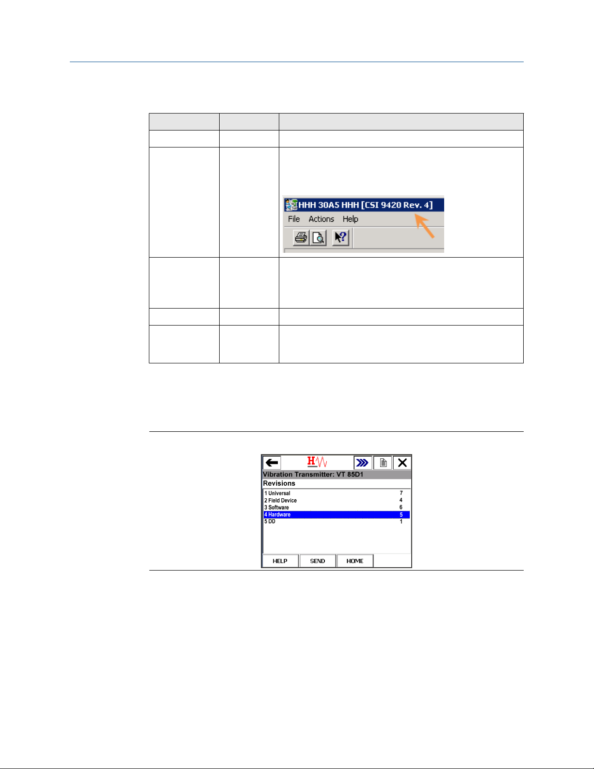
Device revision information
Revision Current level Description
Universal 7 This is the HART version the transmitter supports.
Field device
Software 8 This is the current software version.
Hardware 5 This is the hardware revision.
1
4 This is the major revision of the transmitter and corresponds
with a major interface release.
When using AMS Device Manager, this revision can be found on
the screen title.
The software may be occasionally modified to refine
functionality. When major functionality is added, the device
revision increases.
DD 1 This is the Device Descriptor (DD) revision.
The device descriptor is primarily used for configuring devices in
the field.
1
If you have an older device revision, a factory upgrade may be possible in some cases. Contact
Product Support for more information.
You can view the revision information in a Field Communicator and in AMS Device
Manager.
Figure 1-2: Revision numbers in a 475 Field Communicator
MHM-97408, Rev 22 9

Introduction Reference Manual
September 2020 MHM-97408
Figure 1-3: Revision numbers in AMS Device Manager
10 MHM-97408, Rev 22

Reference Manual Introduction
MHM-97408 September 2020
1.3 Considerations
General
Electrical vibration sensors, such as accelerometers, produce low-level signals proportional
to their sensed vibration. With simple HART configuration, the transmitter converts the
low-level sensor signal to a wireless-enabled signal.
Commissioning
The transmitter can be commissioned before or after installation. You can commission it
on the bench before installation to ensure proper operation and to be familiar with its
functions.
Make sure the instruments are installed in accordance with applicable field wiring
practices.
The AMS 9420 device is powered whenever the power module is installed. To avoid
depleting the power module, remove it when the device is not in use.
Installation
When choosing an installation location and position, provide ample access to the
transmitter. For best performance, the antenna should be vertical, with some space
between objects in a parallel metal plane such as a pipe or metal framework. Pipes or
framework may adversely affect the performance of the antenna.
Power Module
There are two power modules that may be used with the AMS 9420.
Where approved for use, Emerson recommends using the blue power module . The blue
power module is equipped with two "D" size primary lithium/thionyl chloride cells, and
features special power management circuitry for optimum performance with the AMS
9420. Each blue power module contains approximately 10 grams of lithium. The black
power module contains two “C” size primary lithium/thionyl chloride batteries. The black
power module contains approximately 5 grams of lithium; therefore, the blue power
module will operate the AMS 9420 for approximately twice as long as the black power
module.
Note
When upgrading from the black power module to the blue power module, be sure to
order an extended battery cover for each blue power module. To order an extended
battery cover for the blue aluminum housing or the stainless steel housing, contact your
local sales representative.
Under normal conditions, power module materials are self-contained and not reactive as
long as the integrity of the batteries and power module pack are maintained. Take care to
prevent thermal, electrical, or mechanical damage, and protect contacts to prevent
premature discharge.
CAUTION
Use caution when handling power modules. Power modules may be damaged if dropped
from heights in excess of 20 feet.
MHM-97408, Rev 22 11

Introduction Reference Manual
September 2020 MHM-97408
Electrical
Emerson
A9000Px
series
adapters
A power adapter is available to connect the AMS 9420 to an external 11-28
VDC power source. This is used in place of the power module.
When used with a barrier on the power input, the AMS 9420 has the same
ratings for hazardous location requirements.
Power in and external sensors must be wired via separate entries.
An external earth connection, where applicable, should be made to the
earth grounding point on the bottom of the housing.
The full assembly shall maintain a minimum IP rating of IP20.
Field wiring using multiconductor cable shall either have each conductor
enclosed in grounded metal shield or each conductor have a minimum of
0.25 mm (0.01 in) insulation thickness.
Sensor
Make sensor connections through the cable entry at the side of the
connection head. Provide adequate clearance for cover removal.
Environmental
The transmitter operates within specifications for ambient temperatures between –40°F
and 185°F (–40°C and 85°C).
Verify that the operating environment of the transmitter is consistent with the appropriate
hazardous location certifications.
1.4 Return of materials
You may need to ship the device to an Emerson Product Service Center for return or
maintenance. Before shipping, contact Emerson Product Support to obtain a Return
Materials Authorization (RMA) number and receive additional instructions.
Emerson Product Support contact information:
Phone
Email
Web
Toll free 800.833.8314 (U.S. and Canada)
+1.512.832.3774 (Latin America)
+63.2 702.1111 (Asia Pacific, Europe, and Middle East)
ap-sms@emerson.com
http://www.emerson.com/en-us/contact-us
Note
If the transmitter has been exposed to hazardous substances, a Material Safety Data Sheet
(MSDS) must be included with the returned materials. An MSDS is required by law to be
available to people exposed to specific hazardous substances.
Shipping considerations for wireless products (Lithium Batteries)
• The unit was shipped to you without the power module installed. Please remove the
power module prior to shipping the unit.
• Each blue power module contains two "D" size primary lithium-thionyl chloride battery
cells; each black power module contains two "C" size primary lithium-thionyl chloride
battery cells. Primary lithium batteries are regulated in transportation by the U.S.
12 MHM-97408, Rev 22

Reference Manual Introduction
MHM-97408 September 2020
Department of Transportation, and are also covered by IATA (International Air
Transport Association), ICAO (International Civil Aviation Organization), and ADR
(European Ground Transportation of Dangerous Goods).
• It is the responsibility of the shipper to ensure compliance with these or any other local
requirements. Please consult current regulations and requirements before shipping.
MHM-97408, Rev 22 13

Install the AMS 9420 Reference Manual
September 2020 MHM-97408
2 Install the AMS 9420
Topics:
• 2.1
• 2.2 Power the AMS 9420 with a power module
• 2.3
• 2.4 Install the end cap
• 2.5 Position the antenna
• 2.6 Liquid Crystal Display (LCD)
• 2.7 Ground the transmitter
Before beginning installation procedures:
Insert the power module only when you are ready to commission the device.
Install the Emerson Wireless Gateway and ensure it functions properly before you activate
the AMS 9420 or any other wireless devices. Power up wireless devices in order of
proximity from the Emerson Wireless Gateway, beginning with the closest. This will result
in a simpler and faster network installation.
Sensors
Power the AMS 9420 with external DC power
WARNING
If the sensor is installed in a high-voltage environment and a fault condition or installation
error occurs, the sensor leads and transmitter terminals could carry lethal voltages. Use
extreme caution when making contact with the leads and terminals.
2.1 Sensors
Each of the AMS 9420 signal inputs uses accelerometers to make vibration measurements.
The term "sensor" applies to both an accelerometer and an accelerometer with embedded
temperature; the word “accelerometer” refers to a sensor that measures only
acceleration. The AMS 9420 uses special low-power sensors (available for purchase from
Emerson) to reduce power consumption and increase power module life. The sensor is
available with or without embedded temperature.
You can use 100 mV/g sensors with the AMS 9420 if you connect the sensors and external
DC power to the Emerson A9000PS-A power adapter.
2.1.1 Sensor operating limits
Low-power sensors with 25 mV/g nominal sensitivity are required when connecting
directly to the AMS 9420 terminals. The Emerson A9000PS-A adapter is required for ICP
accelerometers with a nominal sensitivity of 100 mV/g.
Table 2-1: Standard, low-power sensor operational ranges
Channel DC bias range DC input range AC input range
Accelerometer 1 2–3 VDC 0–5 VDC 0.5–4.5 V (+/-80 g's peak)
14 MHM-97408, Rev 22
®

Reference Manual Install the AMS 9420
MHM-97408 September 2020
Table 2-1: Standard, low-power sensor operational ranges
Channel DC bias range DC input range AC input range
Accelerometer 2 2–3 VDC 0–5 VDC 0.5–4.5 V (+/-80 g's peak)
Temperature 1 N/A -40°C to 125°C N/A
The accelerometers require a DC bias. The AMS 9420 provides the necessary bias and
measures it to verify correct sensor operation. The nominal bias voltage is 2.5 V. If the bias
voltage is outside of the 2–3 V range, the device generates a failed alert for the associated
sensor. The DC input range represents the operational DC range of the signal input. The
AC input range represents the operational AC range of the signal input.
2.1.2 Sensor handling
Note
Each sensor requires a standard 1/4–28-inch mounting location.
CAUTION
Do not drop, hammer, or impact the sensor housing before, during, or after installation.
CAUTION
(continued)
Do not exceed the specified torque when tightening a stud-mounted sensor. Overtightening a sensor will damage the sensing element and void the manufacturer’s
warranty.
CAUTION
Although the integral cable has a built-in strain relief, do not use excessive force when
pulling the cable. Do not exert more than 5-lb of force directly on the sensor connection
during installation. If possible, secure the cable to the machine near the point of sensor
installation.
CAUTION
Do not exert more than 5-lb pull force directly on sensor/cable connection during wire
pulls.
For sensors that have been mounted before pulling the cable through the conduit or
raceway to the AMS 9420, leave the cable bundled and secured to the machine.
Permanent signal degradation takes place when cables are damaged. Do not step on, kink,
twist, or pinch cables. Also take note of the placement of the cable bundle. Do not place
bundles in a manner that may cause strain at the sensor/cable connection.
MHM-97408, Rev 22 15

Install the AMS 9420 Reference Manual
September 2020 MHM-97408
WARNING
If the sensor is installed in a high-voltage environment and a fault condition or installation
error occurs, the sensor leads and transmitter terminals could carry lethal voltages. Use
extreme caution when making contact with the leads and terminals.
For high-voltage environments, attach the sensor leads first before connecting to a power
source.
Tip
Use Spade lugs to improve long-term reliability of sensor wiring.
2.1.3 Sensor mounting/attachment tools and supplies
Mounting tools
• Drill
• Spot face or end mill tool
The spot face tool attaches to a standard electric drill and provides a machined surface
that is at least 1.1 times greater than the diameter of the sensor. The spot face tool also
drills a pilot hole that can then be tapped for a stud mounted sensor.
You can purchase the spot face tool from Emerson (MHM P/N 88101), or you can
substitute a spot face tool with similar characteristics as required. Contact your local sales
representative for assistance.
Figure 2-1: Spot face or end mill tool
Attachment tools and supplies
• 40-200 inch-lb torque wrench with 1/8 in. hex bit
Suggested vendor: Grainger (P/N 4YA74)
Description: 3/8" drive inch-lb torque wrench. You can substitute with any torque
wrench with a range of 40 to 70 inch-lb and less than 5 inch-lb increments.
• 1/4-28" taps and tap handle
• 9/16" open-end wrench
• 1/8" hex Allen key
• Wire brush
16 MHM-97408, Rev 22

Reference Manual Install the AMS 9420
MHM-97408 September 2020
• Plant-approved cleaner/degreaser
• Plant-approved semi-permanent thread locker (e.g. Loctite)
For epoxy mount, you also need the following:
• 2-part epoxy (e.g. Loctite Depend [Emerson P/N A92106] or comparable)
• A212 Mounting Pads
Figure 2-2: A212 mounting pad
• (Optional) Grinder – to create a sufficiently flat mounting surface
2.1.4 Prepare the sensor mount
Stud mount (preferred)
Stud mount provides increased reliability, improved frequency response, and increased
signal sensitivity.
Prerequisites
The mounting location must provide a flat surface of at least 0.5 in. (12.7 mm) in diameter
and a case thickness exceeding 0.4 in. (10.2 mm). If this is not possible, use the epoxy
mount method instead
Procedure
Prepare the spot face or end mill tool by setting the drill bit depth to a minimum of
1.
0.325 in. (8.255 mm).
2.
Using a wire brush and plant-approved cleaner, clean and degrease the surface
area.
Keeping the spot face and end mill tool perpendicular to the machine surface, drill
3.
into the mounting location until the surface is smooth to the touch with no
noticeable irregularities. This may require the spot face tool to remove as much as
0.04 in. (1.016 mm) or more from the surface.
Note
If the spot face is not uniform on all sides, it indicates that the spot face tool is not
perpendicular to the mounting surface, and the resulting surface will not allow the
sensor to be mounted properly. See Sensor mounting diagrams for illustrations of
the correct milling process.
4. Using 1/4-28 in. tap set, tap a pilot hole to a minimum depth of 0.25 in. (6.35 mm).
See Sensor mounting diagrams for an illustration of tapping a pilot hole.
MHM-97408, Rev 22 17

Install the AMS 9420 Reference Manual
September 2020 MHM-97408
Epoxy mount (alternative)
If it is not practical to drill into the machine casing, then the epoxy mount method is
acceptable.
Procedure
1. If the equipment surface has a radius of curvature that is less than 4 in. (100 mm),
grind a flat surface approximately 0.5 in. (12.7 mm) in diameter.
2. Using a wire brush and plant-approved cleaner, clean and degrease the surface
area.
3.
Using a 2-part epoxy (such as Emerson P/N A92106), spray the activator onto the
mounting surface. Place a light coat of epoxy on the surface of the mounting pad
and hold firmly against the machine spot face surface for 1 minute.
Note
If the adhesive does not set within 1 minute, it indicates that too much epoxy is
applied or that the mounting surface is not prepared properly. Repeat steps 2–3.
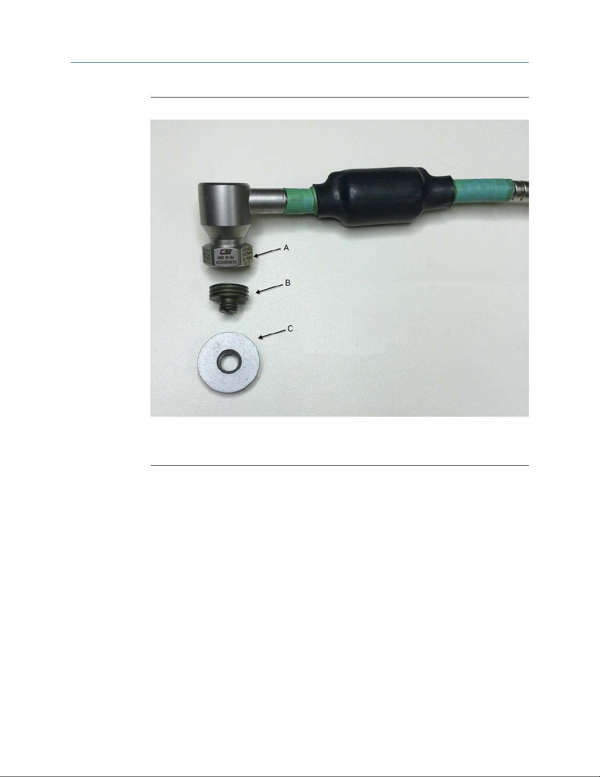
2.1.5 Attach the sensors
Figure 2-3 shows a typical accelerometer, mounting stud, and mounting pad used with
the AMS 9420. The mounting pad is only necessary when doing an epoxy mount.
18 MHM-97408, Rev 22
Reference Manual Install the AMS 9420
MHM-97408 September 2020
Figure 2-3: Accelerometer, mounting stud, and optional mounting pad
A. accelerometer
B. mounting stud (included with the accelerometer)
C. mounting pad
Prerequisites
Whenever possible, mount sensors to the machine while pulling cables. If you have to
mount the sensor at another time, secure the bundled cable to the machine and protect it
from damage.
Procedure
1. Using a plant-approved cleaner/degreaser, remove any lubricating fluid used during
the tapping process and if necessary, clean the mounting stud threads.
2. Rub a small amount of semi-permanent thread locker onto the mounting location.
MHM-97408, Rev 22 19

Install the AMS 9420 Reference Manual
September 2020 MHM-97408
Figure 2-4: Apply thread locker onto mounting location
3. Using a 1/8 in. Allen key (English mounting stud) or a 4 mm Hex Allen key (metric
mounting stud), loosely screw the mounting stud into the mounting location.
The mounting location is the machine surface when using stud mount and the
mounting pad when using epoxy mount.
4. Using a torque wrench with 1/8 in. hex bit, torque to 7–8 ft-lb (9.5–10.8 N-m) to
tighten the mounting stud.
Figure 2-5: Tighten the mounting stud
20 MHM-97408, Rev 22

Reference Manual Install the AMS 9420
MHM-97408 September 2020
For stud mount: If the mounting stud is still not seated against the spot face after
you apply the correct torque force, it indicates that the tap hole is not deep enough.
Remove the mounting and tap a deeper hole.
5. Apply a thin coat of semi-permanent thread locker to the threads on the sensor
housing.
6. Place the sensor onto the mounting stud and hold it to create the least amount of
cable strain and cable exposure. While holding the sensor, hand-tighten the 9/16 in.
captive nut and use a torque wrench with 9/16 in. open end to finish tightening to
2–5 ft-lb (2.7–6.8 N-m).
Figure 2-6: Hand-tighten the captive nut
If the mounting stud does not disengage from the sensor, use a flathead
screwdriver to hold the stud and turn the hex nut counter-clockwise with a wrench.
MHM-97408, Rev 22 21
Install the AMS 9420 Reference Manual
September 2020 MHM-97408
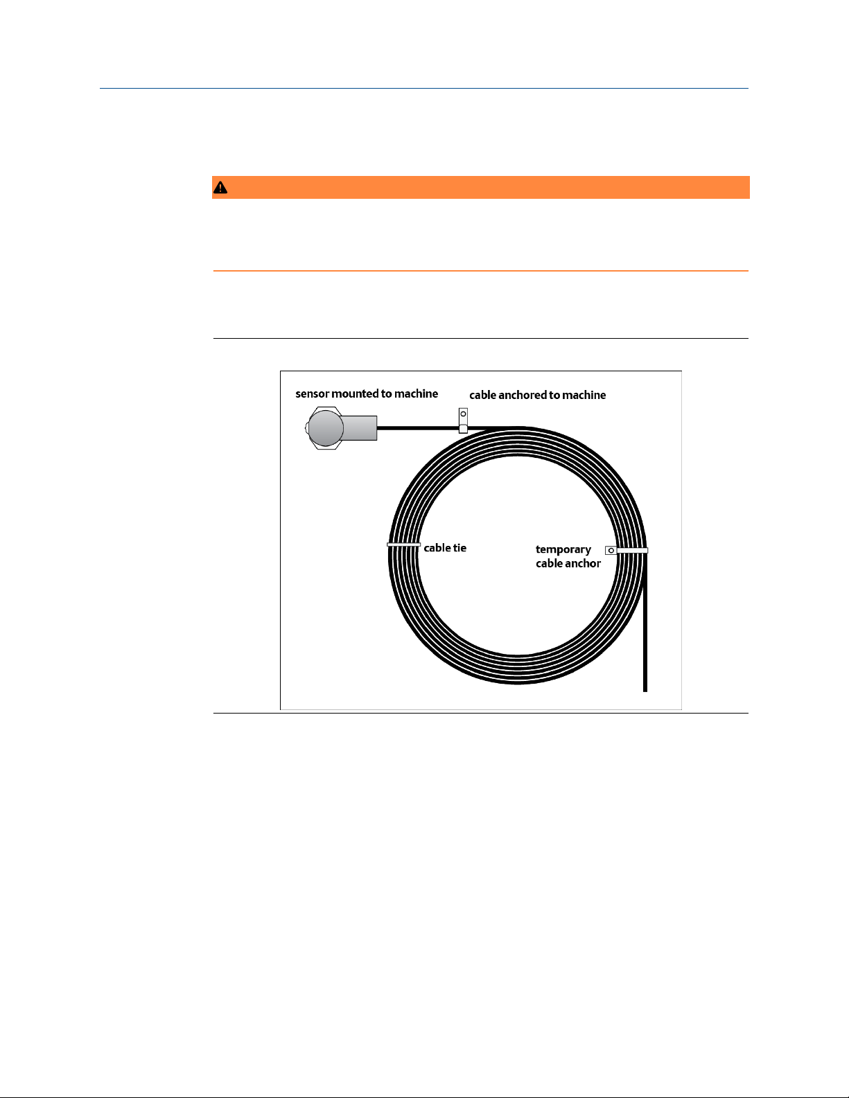
2.1.6 Secure the sensor cables
WARNING
All wiring should be installed by a trained and qualified electrician. Wiring must conform to
all applicable local codes and regulations. Follow local codes and regulations regarding
wire type, wire size, color codes, insulation voltage ratings, and any other standards.
Using an appropriately sized cable clamp, secure the sensor cable to the machine
approximately 4–5 in. (100–125 mm) from the mounting location. Do not curl into a
bending radius of less than 2.8 in. (71 mm).
Figure 2-7: Securing a cable with temporary cable anchor
If the pulling of cables is not currently scheduled, secure the bundled sensor cables so that
no strain is placed on the integral sensor/cable connectors. Do not let the bundled cable
hang from the sensors. Do not place cables on plant floors, maintenance access areas,
and/or footholds that may cause damage to the cables.
22 MHM-97408, Rev 22

Reference Manual Install the AMS 9420
MHM-97408 September 2020
2.1.7 Conduit installation guidelines
WARNING
All wiring should be installed by a trained and qualified electrician. Wiring must conform to
all applicable local codes and regulations.
• Adhere to IEEE 1100 specifications for grounding.
• Do not exceed a 40 percent fill for conduits.
• Route the conduit away from power trays using these guidelines:
6 in. 110 VAC
12 in. 220 VAC
24 in. 440 VAC
• Attach the conduit to the NPT threaded holes on the side of the AMS 9420.
MHM-97408, Rev 22 23

Install the AMS 9420 Reference Manual
September 2020 MHM-97408
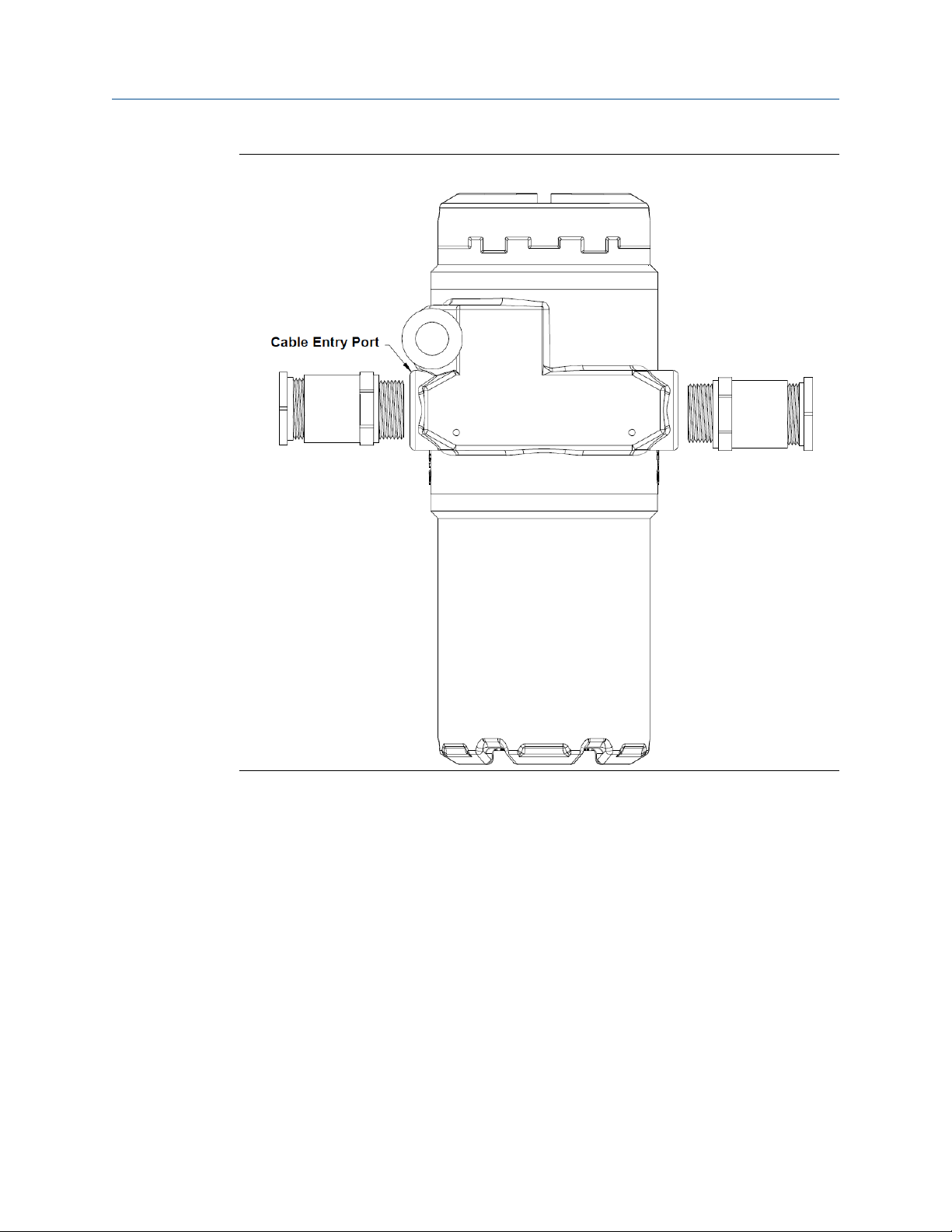
2.1.8 Cable entry port installation guidelines
Power leads and sensor leads enter the rear compartment of the transmitter housing
through conduit openings on the left and right of the housing. Power leads and sensor
leads must enter on opposite sides of the housing. Emerson recommends the sensor leads
enter the same side where the sensor terminal screws are located. Depending on how the
transmitter is powered, you may need to install two sensor cables into one cable entry
port. When the transmitter uses a power module, both cable entry points are available for
use with sensors. You can use the standard cable glands included with the transmitter for
one sensor cable per cable gland. The included cable gland is not approved for use with
two sensor cables. When the transmitter uses external DC power, an extra conduit body is
required, and both sensor leads enter the same conduit opening. Refer to the installation
drawing for details.
Note
Use cable glands to seal the cable entry ports. Ensure that the cable gland grommet fits
the wire properly and does not leak. The wire must snugly fit in the grommet feed-through
in the cable gland to prevent ingress of water and other contaminants. If using one of the
grommets for the standard low-power accelerometers, use a cable with a diameter
between 0.125 to 0.250 in. (3.175 - 6.35 mm) to maintain a good seal. If a good seal is not
possible with the wire selected, use an alternative grommet that provides a good seal.
The following figures show suggested installations.
24 MHM-97408, Rev 22
Reference Manual Install the AMS 9420
MHM-97408 September 2020
Figure 2-8: AMS 9420 with extended power module and two sensors
MHM-97408, Rev 22 25

Install the AMS 9420 Reference Manual
September 2020 MHM-97408
Figure 2-9: AMS 9420 with external DC power and two sensors
Notes
• When using two sensors with external DC power a dual cable gland adapter is required
(e.g. 'T'-adapter shown in Figure 2-9).
• An external earth connection, where applicable, should be made to the earth
grounding point on the bottom of the housing.
• If using a Stainless Steel housing, stainless steel adapters/glands are also
recommended.
• To ensure long term reliability a minimum of IP56 or NEMA 4 sealing is recommended
for the full assembly.
• All local wiring codes and regulations shall be followed.
When installed in a hazardous location, the following practices are also required:
• Both sensors must enter through the dual cable gland adapter with one sensor per
entry.
• The full assembly shall maintain a minimum IP rating of IP20.
• Field wiring using multiconductor cable shall either have each conductor enclosed in
grounded metal shield or each conductor have a minimum of 0.25 mm (0.01 in)
insulation thickness.
26 MHM-97408, Rev 22

Reference Manual Install the AMS 9420
MHM-97408 September 2020
2.1.9 Attach sensor wiring to the AMS 9420 terminals
Prerequisites
This procedure applies to a typical AMS 9420 installation with low-power sensors. Lowpower accelerometers connect directly to the transmitter terminal block. For information
about using ICP® accelerometers, refer to Power the AMS 9420 with external DC power.
• If you are using armor-jacketed cable longer than 3 meters, you must attach the
ferrites before attaching sensor wiring the AMS 9420 terminals. See Attach 3 ferrites to
an accelerometer with armor-jacketed cable.
• If the sensor signal wires are not equipped with spade lugs, Emerson recommends
installing them before proceeding.
Procedure
1. Tie the sensor's grounding wire (white with black stripe) to the ground screw inside
the AMS 9420.
See callout E in the figures below.
2. Refer to the appropriate figure to connect the sensor signal wires.
Note
You can connect one or two accelerometers to the AMS 9420. You can connect only
one accelerometer with a temperature sensor.
a) Insert a beryllium copper washer on top of each spade lug.
b) Tighten the screw to 15 in-lbs (1.7 N-m).
MHM-97408, Rev 22 27

Install the AMS 9420 Reference Manual
September 2020 MHM-97408
Figure 2-10: AMS 9420 wiring with one accelerometer
A Sensor power Red wire
B Sensor signal White wire
C Unused Unused
D Sensor common Black wire
E Sensor grounding White wire with black stripe
28 MHM-97408, Rev 22

Reference Manual Install the AMS 9420
MHM-97408 September 2020
Figure 2-11: AMS 9420 wiring with two accelerometers
A Sensor power 2 red wires
B Sensor 1 signal White wire
C Sensor 2 signal White wire
D Sensor common 2 black wires
E Sensor grounding 2 white wires with black stripe
MHM-97408, Rev 22 29

Install the AMS 9420 Reference Manual
September 2020 MHM-97408
Figure 2-12: AMS 9420 wiring with one accelerometer with embedded
temperature
A Sensor power Red wire
B Vibration signal (Signal 1) White wire
C Temperature signal (Signal 2) Green wire
D Sensor common Black wire
E Sensor grounding Bare wire
2.2 Power the AMS 9420 with a power module
Emerson offers power modules to power the AMS 9420 for typical applications. The power
module package includes more documentation. This section includes examples of using
the Blue Power Module with the AMS 9420.
2.2.1 Power module installation and replacement
There are two power modules that may be used with the AMS 9420.
Where approved for use, Emerson recommends using the blue power module . The blue
power module is equipped with two "D" size primary lithium/thionyl chloride cells, and
features special power management circuitry for optimum performance with the AMS
9420. Each blue power module contains approximately 10 grams of lithium.
The black power module contains two “C” size primary lithium/thionyl chloride batteries.
The black power module contains approximately 5 grams of lithium; therefore, the blue
power module will operate the AMS 9420 for approximately twice as long as the black
power module.
30 MHM-97408, Rev 22

Reference Manual Install the AMS 9420
MHM-97408 September 2020
Actual power module life can vary dramatically based on the power module being used
and on operating parameters, including whether high-resolution data such as vibration
waveforms and/or spectra are being retrieved from the device.
Under normal conditions, power module materials are self-contained and not reactive as
long as the integrity of the batteries and power module pack are maintained. Take care to
prevent thermal, electrical, or mechanical damage, and protect contacts to prevent
premature discharge.
Upgrading
If you need to upgrade from black power module to a blue power module, Emerson
personnel must apply a new label to your transmitter.
Note
When upgrading from the black power module to the blue power module, be sure to
order an extended battery cover for each blue power module. To order an extended
battery cover for the blue aluminum housing or the stainless steel housing, contact your
local sales representative.
Handling
Under normal conditions, the power module materials are self-contained and are not
reactive as long as the batteries and the power module pack integrity are maintained.
Take care to prevent thermal, electrical, or mechanical damage. Protect the contacts to
prevent premature discharge.
CAUTION
Use caution when handling the power module pack. The power module pack can be
damaged if dropped from heights in excess of 20 feet.
WARNING
Power module hazards remain even when cells are discharged.
Environmental considerations
As with any battery, consult local, national, and international environmental rules and
regulations for proper management of spent batteries. If no specific requirements exist,
you are encouraged to recycle through a qualified recycler. Consult the materials safety
data sheet for power module-specific information.
Shipping
The unit is shipped without the power module installed. Unless you are specifically
instructed to do otherwise, always remove the power module pack from the unit prior to
shipping.
The U.S. Department of Transportation, International Air Transport Association (IATA),
International Civil Aviation Organization (ICAO), and European Ground Transportation of
Dangerous Goods (ADR) regulate the transportation of primary lithium batteries
The shipper is responsible for complying with these or any other local requirements.
Consult current regulations and requirements before shipping.
MHM-97408, Rev 22 31

Install the AMS 9420 Reference Manual
September 2020 MHM-97408
2.2.2 Physical installation
The Blue Power Module (A0701PBU) has been designed with safety in mind. The
connector is keyed so that it cannot be inserted incorrectly, and it uses a patented
mechanism that enables it to be replaced while the transmitter is installed in a hazardous
area. The installation procedure includes replacing the power module and extended
battery cover.
Prerequisites
When replacing a standard Black Power Module with the extended life Blue Power Module,
you also need to replace the smaller end cap (2.5 in / 70 mm) with the extended end cap
(4.5 in / 115 mm).
Procedure
1. Inspect the power module for any obvious signs of damage.
Emerson's SmartPower Power Modules are designed to be rugged. The product
design has been tested in environmental conditions such as extreme temperature,
pressure, vibration and shock. In testing, it also was dropped repeatedly from 3m
height without leading to an unsafe operating condition.
If there are any obvious signs of damage, do not install the power module. Refer to
the Blue Power Module documentation for disposal or recycling of the power
module.
2. Unscrew the power module cover from the AMS 9420.
3.
Connect the power module to the AMS 9420. The power module has a keyed
connection to prevent improper connection.
Figure 2-13: Blue Power Module (A0701PBU) connects using a keyed
connection
32 MHM-97408, Rev 22
Reference Manual Install the AMS 9420
MHM-97408 September 2020
Note
Power up wireless devices in order of proximity from the Emerson Wireless
Gateway, beginning with the closest. This will result in a simpler and faster network
installation.
4. Close the extended end cap on the housing and tighten. Always ensure a proper
seal by installing the electronics housing covers so that metal touches metal, but do
not over tighten.
2.3 Power the AMS 9420 with external DC power
Emerson offers Emerson A9000P series adapters to power the AMS 9420 with external DC
power. The adapter package includes documentation, installation drawings, and other
important instructions. You can also find the quick start guide on our website. This section
includes some examples of using the power adapter with the AMS 9420.
2.3.1 Emerson A9000P description of intended use
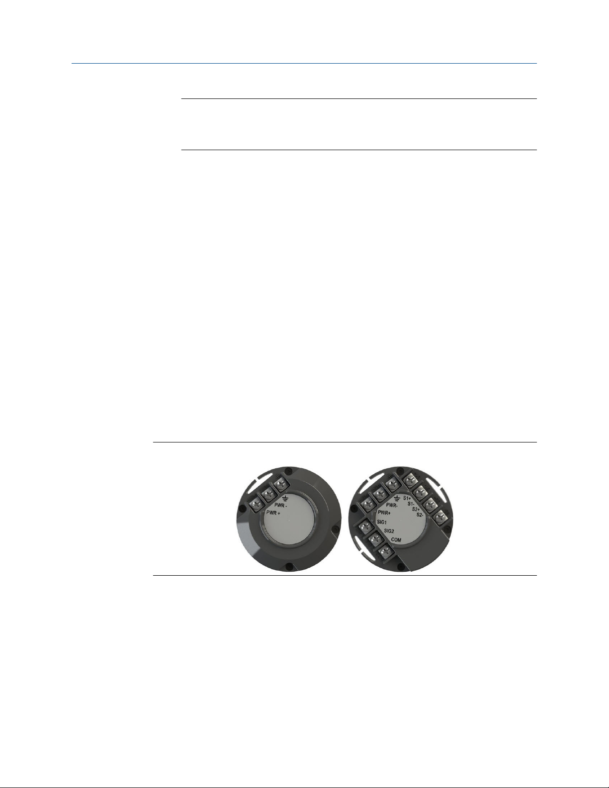
The Emerson A9000P series adapters are available in two versions: Emerson A9000PA and
Emerson A9000PS-A. They allow an Emerson wireless transmitter to be powered by
external DC power. When installed with an appropriate safety barrier, they can be used in a
hazardous location. Barrier requirements are described in the Emerson A9000Px Quick
Start Guide and installation drawings included with the power adapter.
• Use either version to connect external DC power.
• Use the Emerson A9000PS-A to connect external DC power and up to 2 standard ICP
accelerometers with a nominal sensitivity of 100 mV/g.
Figure 2-14: Emerson A9000PA (left) and Emerson A9000PS-A (right)
2.3.2 Optional spacer
The spacer is required only when the transmitter has an extended endcap.
MHM-97408, Rev 22 33

Install the AMS 9420 Reference Manual
September 2020 MHM-97408
Figure 2-15: Optional spacer
2.3.3 Connect external DC power to Emerson wireless transmitters
You can use all versions of the Emerson A9000P series adapters to connect external DC
power to Emerson wireless transmitters. This example describes connecting the power
adapter.
CAUTION
DC power should only be applied to the power adapter after it is wired and inserted in the
transmitter terminal block.
Procedure
1. Connect the external DC power to the power adapter.
2. Connect the included green chassis ground cable to the power adapter ground and
to the chassis ground point.
The connections are shown in detail in the installation drawing and an example is
shown in
Figure 2-16.
34 MHM-97408, Rev 22
Reference Manual Install the AMS 9420
MHM-97408 September 2020
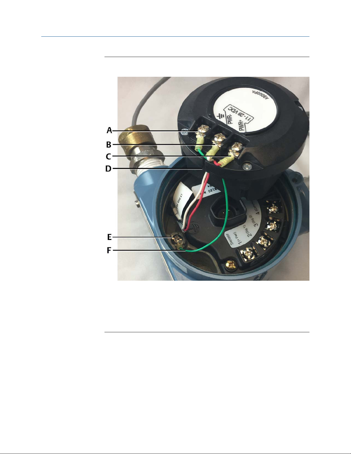
Figure 2-16: External DC power and included cable harness connected to the
power adapter
A. Green chassis ground cable
B. PWR C. PWR +
D.
Slot
E. Chassis ground point
F. Green chassis ground cable
3. Push each wire through the slot.
4. Insert the power adapter into the receptacle on the transmitter terminal block.
5. If the transmitter has an extended end cap, insert the spacer into the end cap.
Otherwise, the spacer is not required.
MHM-97408, Rev 22 35

Install the AMS 9420 Reference Manual
September 2020 MHM-97408
2.3.4 Connect external DC power and ICP® accelerometer inputs to an AMS 9420
With the AMS 9420, use the Emerson A9000PS-A to connect external DC power and up to
2 standard ICP® accelerometers with a nominal sensitivity of 100 mV/g. This example
describes connecting the power adapter.
Note
For a typical AMS 9420 installation, only connect external DC power to the power adapter.
Low-power accelerometers connect directly to the transmitter terminal block.
CAUTION
DC power should only be applied to the power adapter after it is wired and inserted in the
transmitter terminal block.
Prerequisites
Connect external DC power and green chassis ground cable to the power adapter. Refer to
the example in Connect external DC power to Emerson wireless transmitters.
Procedure
1. Use the included cable harness to connect the power adapter sensor terminals to
the AMS 9420, as shown in the installation drawing.
The cable harness has three wires: two colored wires and one bare wire. Each wire
has a spade lug on one end and a ferrule on the other end. Connect the spade lugs
to the terminal block. Connect the ferrules to the power adapter. Be careful to
connect each wire to the matching terminal screw. The connections are shown in
detail in the installation drawing and an example is shown in Figure 2-17
.
36 MHM-97408, Rev 22
Reference Manual Install the AMS 9420
MHM-97408 September 2020
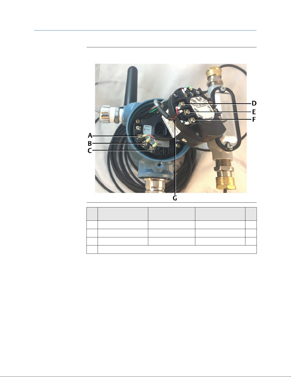
Figure 2-17: Emerson A9000PS-A to AMS 9420 signal connections with
included cable harness
Spade lug to AMS 9420 Cable harness wire Ferrule to Emerson
A9000PS-A
A 2 (Sig 1) color 1 (red shown) SIG1 D
B 3 (Sig 2) color 2 (black shown) SIG2 E
C 4 (Common) unshielded COM F
G Slot
2. Push each wire from the cable harness into the slot. It is easier to push the individual
wires into the slot after connecting the ferrules.
3. Connect the leads from up to two standard ICP® accelerometers with a nominal
sensitivity of 100 mV/g to the terminal screws on the Emerson A9000PS-A.
MHM-97408, Rev 22 37
Install the AMS 9420 Reference Manual
September 2020 MHM-97408
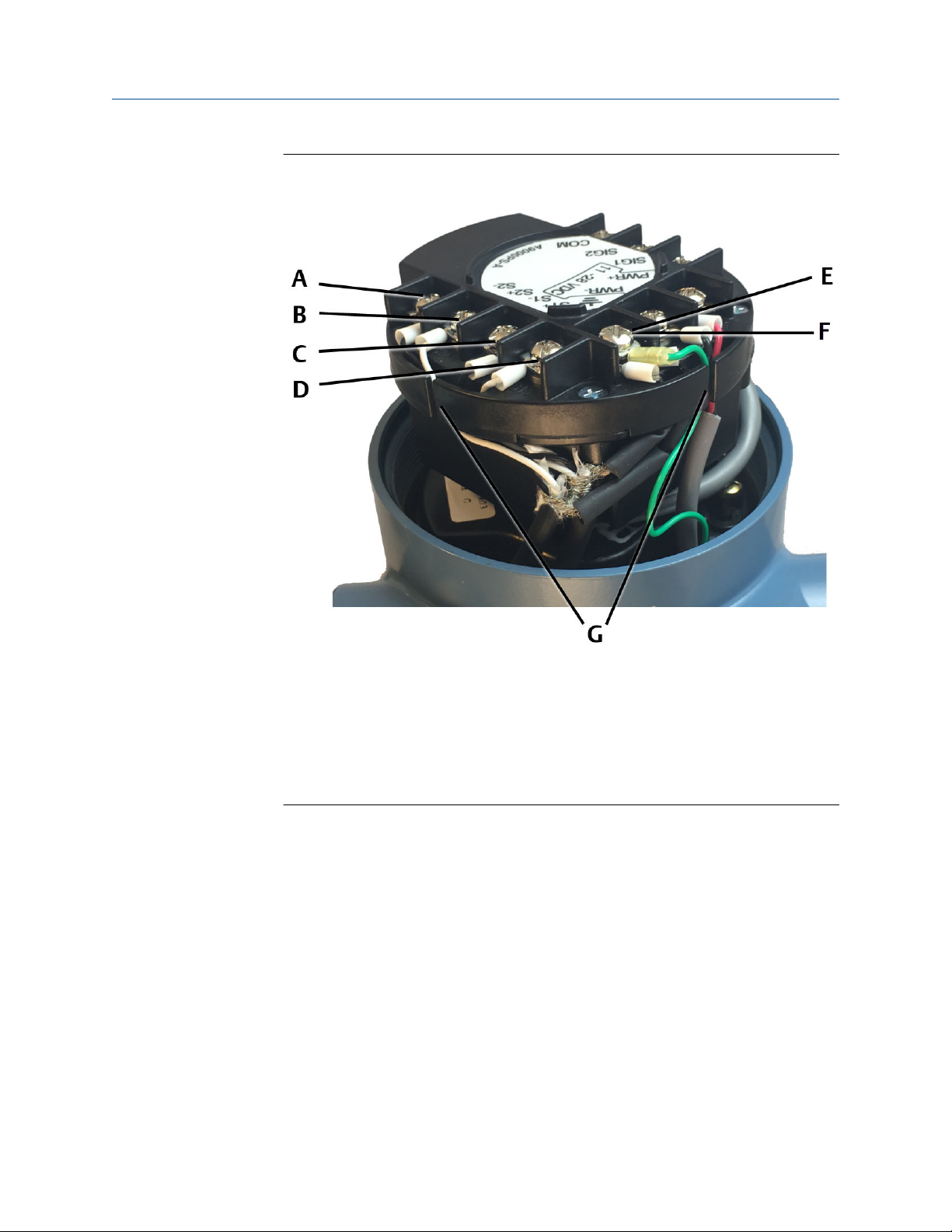
Figure 2-18: Two ICP® accelerometers connected to the power adapter
(rotated view)
A. S2B. S2+
C. S1-
S1+
D.
E. S1 Shield
F. S2 Shield
G. Slots
4. Push each signal cable wire into the slot.
5. Wrap the cable harness counter clockwise around the receptacle on the transmitter
terminal block.
38 MHM-97408, Rev 22

Reference Manual Install the AMS 9420
MHM-97408 September 2020
Figure 2-19: Cable harness wrapped around the receptacle
6. Insert the power adapter into the receptacle.
7. If the transmitter has an extended end cap, insert the spacer into the end cap.
Otherwise, the spacer is not required.
2.4 Install the end cap
Note
If you have configured the sensor and network but are not ready to commission the
device, remove the power module to extend operating life.
Prerequisites
Ensure you have the appropriate end cap and spacer as required for your application.
Procedure
1. If required for your application, insert the spacer between the power module or
power adapter and the extended end cap.
2. Attach the end cap.
Always ensure a proper seal by installing the housing cover so that metal touches
metal and the black O-ring is no longer visible, but do not over tighten. A tight seal
ensures that water, water vapor, or other gases do not penetrate into the housing.
MHM-97408, Rev 22 39
Install the AMS 9420 Reference Manual
September 2020 MHM-97408
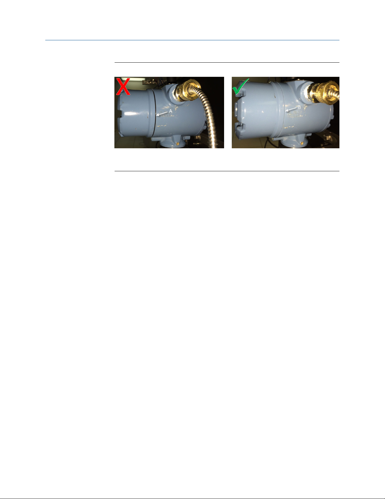
Figure 2-20: Sealing the end cap
A. Improperly sealed end cap. Black O-ring is still visible.
B. Properly sealed end cap. Black O-ring is no longer visible.
3. Use a strapping wrench to tighten the housing cover to safety specification.
Always ensure a proper seal by installing the housing cover so that metal touches
metal and the black O-ring is no longer visible, but do not over tighten. A tight seal
ensures that water, water vapor, or other gases do not penetrate into the housing.
2.5 Position the antenna
Procedure
Position the antenna so it points upward, for optimal performance.
The antenna should be approximately 3 ft. (1 m) from any large structure, building, or
conductive surface to allow for clear communication to other devices.
40 MHM-97408, Rev 22

Reference Manual Install the AMS 9420
MHM-97408 September 2020
Figure 2-21: Antenna positions and dimensions
MHM-97408, Rev 22 41

Install the AMS 9420 Reference Manual
September 2020 MHM-97408
2.6 Liquid Crystal Display (LCD)
If you order an LCD, it is shipped attached to the transmitter.
2.6.1 Rotate the LCD
You may need to rotate the LCD depending on the mounting orientation of the device.
WARNING
Do not remove the front electronics end cap or LCD cover while the device is in a
hazardous area.
Removing the cap while the device is in a hazardous area could cause an explosion which
could result in death or serious injury.
CAUTION
The front electronics end cap or LCD cover is certified for hazardous areas in appropriate
gas environments (check the nameplate on the device for details).
Exposing the electronics to a production environment may allow particulates, moisture,
and other airborne chemicals to enter into the device, which could lead to contamination
and potential product performance issues.
Figure 2-22: Installing the LCD
Procedure
1. Remove the LCD cover.
2. Insert the four-pin connector into the interface board, rotate to the correct
position, and snap into place.
The pins can be plugged into any one of four locations depending on which angle of
rotation is desired for the LCD screen.
If the LCD pins are inadvertently removed from the interface board, carefully reinsert the pins before snapping the LCD in place.
42 MHM-97408, Rev 22

Reference Manual Install the AMS 9420
MHM-97408 September 2020
After installation, you can remove the LCD by squeezing the two tabs and pulling
gently. You can then rotate it in 90-degree increments and snap it back in place.
3. Attach the LCD cover.
Always ensure a proper seal by installing the housing cover so that metal touches
metal and the black O-ring is no longer visible, but do not over tighten. A tight seal
ensures that water, water vapor, or other gases do not penetrate into the housing.
Figure 2-23: Sealing the end cap
A. Improperly sealed end cap. Black O-ring is still visible.
B. Properly sealed end cap. Black O-ring is no longer visible.
Important
Moving one LCD around to multiple devices, on an “as need” basis, is NOT
recommended. This can cause reliability problems over time. The connector pins on
the LCD are not designed for repeated connect/disconnect.
2.6.2 Enable the LCD
When you enable the LCD, the AMS 9420 displays information about its network state and
its measurements. This is helpful for configuration, installation, and commissioning. The
LCD provides a visual indication on the status of the device and shows its current
measurements.
Transmitters ordered with the LCD are shipped with the display installed but with the LCD
disabled/turned off. You need to enable the LCD using a 475 Field Communicator or using
AMS Device Manager.
Enable the LCD using a 475 Field Communicator
1. Use the lead set to connect the Field Communicator to the AMS 9420 terminal
block.
2. Turn on the Field Communicator.
3. Select Configure → Manual Setup → General Settings → LCD Mode → Periodic
Display.
Options available for LCD configuration include:
• Not installed – Use this setting if the LCD is not installed.
MHM-97408, Rev 22 43

Install the AMS 9420 Reference Manual
September 2020 MHM-97408
• Periodic Display – Use this setting to show only relevant data. This setting does
not extend the wake cycle.
• Troubleshooting Display – Use this setting when troubleshooting the
transmitter.
• Off – Use this setting to disable the LCD.
Enable the LCD using AMS Device Manager
Launch AMS Device Manager and locate the network where the AMS 9420 is
1.
connected.
2. Right-click the AMS 9420 device and select
3. Click the General Settings tab and from the LCD Mode drop-down menu, select
Periodic Display.
Options available for LCD configuration include:
• Not installed – Use this setting if the LCD is not installed.
• Periodic Display – Use this setting to show only relevant data. This setting does
not extend the wake cycle.
• Troubleshooting Display – Use this setting when troubleshooting the
transmitter.
• Off – Use this setting to disable the LCD.
Note
When operating the AMS 9420 with the Smart Power Module, disable the LCD in the
transmitter configuration after installation to maximize power module life. While the LCD
module itself consumes very little power, having it activated will alter the operating cycle
of the transmitter in such a way that can impact the power module life by up to 15–20%.
2.6.3 Turn on the LCD
WARNING
Configure → Manual Setup.
Do not remove the front electronics end cap or LCD cover while the device is in a
hazardous area.
Removing the cap while the device is in a hazardous area could cause an explosion which
could result in death or serious injury.
CAUTION
The front electronics end cap or LCD cover is certified for hazardous areas in appropriate
gas environments (check the nameplate on the device for details).
Exposing the electronics to a production environment may allow particulates, moisture,
and other airborne chemicals to enter into the device, which could lead to contamination
and potential product performance issues.
44 MHM-97408, Rev 22

Reference Manual Install the AMS 9420
MHM-97408 September 2020
Procedure
1. Remove the LCD cover.
2. Press the
This displays the Tag name, Device ID, Network ID, Network Join Status, and Device
Status screens.
3. Attach the LCD cover.
Use a strapping wrench to tighten the cover until it will no longer turn and the black
O-ring is no longer visible. Refer to Figure 2-23 for an illustration on how to properly
seal the end cap.
DIAG button to turn the LCD on.
2.7 Ground the transmitter
The transmitter operates with the housing, either floating or grounded. However, the
extra noise in floating systems affects many types of readout devices. If the signal appears
noisy or erratic, grounding the transmitter at a single point may solve the problem.
You can reduce electrostatic current in the leads induced by electromagnetic interference
by shielding. Shielding carries the current to the ground and away from the leads and
electronics. If the transmitter end of the shield is adequately grounded to the transmitter
and the transmitter is properly grounded to the earth ground, very minimal current enters
the transmitter.
If the ends of the shield are left ungrounded, a voltage is created between the shield and
the transmitter housing, and between the shield and earth at the element end. The
transmitter may not be able to compensate for this voltage, causing it to lose
communication and/or generate an alarm. Instead of the shield carrying the current away
from the transmitter, the current flows through the sensor leads and into the transmitter
circuitry where it interferes with circuit operation.
Each accelerometer contains a drain wire that is connected to the sensor shield. This wire
should be connected to the internal grounding screw attached to the housing near the
terminal block.
Ground the transmitter in accordance with local, national, and international installation
codes. You can ground the transmitter through the process connection, the internal case
grounding terminal, or the external grounding terminal.
MHM-97408, Rev 22 45

Configure the AMS 9420 Reference Manual
September 2020 MHM-97408
3 Configure the AMS 9420
Topics:
• 3.1
• 3.2 Configuration with a Field Communicator
• 3.3
• 3.4 Configuration with AMS Machinery Manager
Configuration overview
Configuration with AMS Device Manager
3.1 Configuration overview
You can configure the AMS 9420 either prior to installation or after the device is installed
at the measurement location. You do not need to physically install or connect to the
transmitter to complete the configuration. The transmitter, however, reports an alert until
the sensor is connected; this is the expected behavior.
Note
The specific user interface for performing the configuration varies depending on the host
used.
Procedure
1. Connect to a wired HART interface.
Skip this step if your AMS 9420 is purchased pre-configured from the factory.
2. Set the wireless network credentials (Network ID and Join Key) using wired
connection.
Perform this step for the device to join a wireless network. After the device has
joined, you can complete the rest of the steps over a wireless link.
3.
(Optional)
By default, the tag is VT xxxx, where xxxx is the unique radio ID on the wireless
network. The device joins the network and operates correctly even if no changes are
made, but it is usually preferable to name the device something meaningful for the
specific application.
4. Specify the type of sensor installed (for example: 1 accelerometer, 1
accelerometer with temperature, or 2 accelerometers) and name the sensor.
The factory default configuration is one accelerometer named SENSOR 1. Complete
this step for different configurations and name the sensor something meaningful
for the specific application.
46 MHM-97408, Rev 22
Name the device (Tag and Device Description).

Reference Manual Configure the AMS 9420
MHM-97408 September 2020
5. Enter the sensor sensitivity setting.
For improved accuracy, replace the nominal sensitivity value of 25 mV/g (2.55 mV
per m/s2) (default) with the value corresponding to your specific sensor. When
using an 100 mV/g sensor with a power adapter, you need to divide the value by
four. See page 53.
6. Specify the units (English, metric, or SI) that will be used for each parameter.
By default, units are set to English, unless the device is shipped to Japan.
7. Specify which measurements (velocity, temperature, etc.) correspond to the
process variables PV, SV, TV, and QV.
By default, PV is the Overall Velocity on sensor 1, SV is the PeakVue measurement
on sensor 1, TV is the sensor 1 bias voltage, and QV is the supply voltage.
8. Specify alert levels.
Determine the thresholds at which measurement alerts will display and determine
the behavior of device alerts.
9. Specify how the parameters will be published (optimized mode or generic
mode).
By default, the device is configured to use generic mode as it provides the most
consistent overall performance.
10. Specify how often the parameters are published (update rate).
The default update rate is once every 60 minutes. A faster update rate is not
recommended, unless the device is powered by an external power source, as it
significantly reduces the power module life.
11. Optimize for power consumption.
Reduce the publish rate and set the LCD mode to Off to minimize power
consumption. As an additional step, you can configure the PowerSave mode
settings to extend the power module life.
12. Configure trending of parameters.
You can trend parameters in multiple locations such as in a plant historian, in AMS
Machinery Manager, and in a DCS control system.
13. If the device configuration will not be managed by a HART DCS (such as
DeltaV), specify whether AMS Machinery Manager can make configuration
changes.
By default, the device is set for a DCS to manage the configuration, and changes
from AMS Machinery Manager are not permitted. You can, however, allow AMS
Machinery Manager to make configuration changes by enabling MHM Access
Control from AMS Device Manager or from a Field Communicator.
14. If the device is licensed for the Advanced Diagnostics application (spectral data
retrieval), configure storage of energy bands, spectra, and waveforms in the
AMS Machinery Manager database.
With the Advanced Diagnostics application, you can collect data on-demand,
automatically at periodic intervals, or on alert. Store on Alert is the recommended
operating mode.
MHM-97408, Rev 22 47

Configure the AMS 9420 Reference Manual
September 2020 MHM-97408
3.1.1 Connect to a wired HART interface
Unless the AMS 9420 is purchased pre-configured from the factory, you must connect it to
a wired HART interface. This is to define device credentials that allow the device to
communicate on your wireless network. You can also define other device configurations
such as sensor type and alert thresholds at this time.
Notes
• Use the wired HART interface only for configuration. Dynamic variables (such as
measured vibration parameters) are not updated when communicating on the wired
interface.
• The AMS 9420 does not communicate simultaneously on both the wired and wireless
HART interfaces. You will lose wireless connectivity when you connect to the wired
HART interface. Configuration changes are not reflected in a wireless host until
connection has been re-established. To avoid loss of synchronization, disconnect hosts
relying on the wireless link when communicating with the device on the wired
interface.
For example, if you are viewing a configuration screen in AMS Device Manager through
a wireless link, and you leave this screen open while making changes with a Field
Communicator, you will have to exit AMS Device Manager and then re-open it (or rescan the device) after the wireless connection has been restored in order to see the
changes.
Procedure
1. Remove the transmitter back cover.
This exposes the terminal block and HART communication terminals.
48 MHM-97408, Rev 22
Reference Manual Configure the AMS 9420
MHM-97408 September 2020
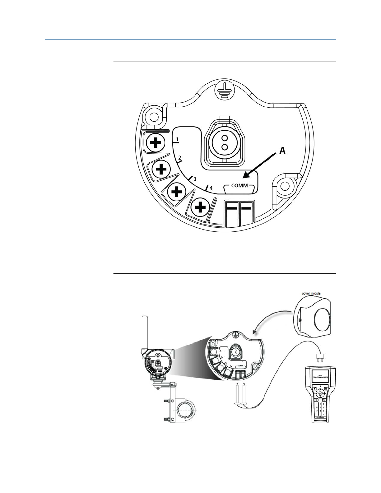
Figure 3-1: AMS 9420 terminal block
A. AMS 9420 COMM terminals (power module version)
2. Connect a power module, if there is not a power source already such as the power
adapter.
Figure 3-2: Field Communicator and power module connection
3. Configure using a Field Communicator, AMS Device Manager, or any HART-enabled
host.
MHM-97408, Rev 22 49

Configure the AMS 9420 Reference Manual
September 2020 MHM-97408
Press Send to send configuration changes to the transmitter.
The AMS 9420 enters “HART Listen” mode for communication on the wired
interface. HART Listen is displayed on the optional LCD, if it is installed.
If the device is unable to enter the HART Listen mode during its boot sequence or
while performing its real-time vibration measurement, retry the initial wired HART
handshaking sequence.
If repeated attempts to establish wired communication fail, you can force the
device into a HART Listen mode. When in a safe location, remove the transmitter
front cover and press the CONFIG button once. The device enters HART Listen
mode, and it remains in this mode until you press the CONFIG button, the power
cycles, or no activity is seen on the wired interface for three minutes. Pressing the
CONFIG button a second time causes the device to exit HART Listen mode.
WARNING
Do not remove the front electronics end cap or LCD cover while the device is in a
hazardous area.
Removing the cap while the device is in a hazardous area could cause an explosion
which could result in death or serious injury.
CAUTION
The front electronics end cap or LCD cover is certified for hazardous areas in
appropriate gas environments (check the nameplate on the device for details).
Exposing the electronics to a production environment may allow particulates,
moisture, and other airborne chemicals to enter into the device, which could lead to
contamination and potential product performance issues. In all cases, whenever
opening the front end cap, be sure to seal it completely afterwards by tightening
until the black O-ring is no longer visible. For an illustration on how to properly seal
the end cap, see Figure 2-23.
4. When configuration is complete over the wired HART interface, disconnect the
transmitter from the communication wires to re-establish wireless communication.
This may take several minutes.
3.1.2 Set the wireless network configuration
This enables the transmitter to communicate with the Emerson Wireless Gateway and
with other systems. This is the wireless equivalent of connecting wires from a transmitter
to a control system input.
Procedure
1. From the Emerson Wireless Gateway, click System Settings
Network Settings to obtain the Network ID and Join Key.
2. Using a Field Communicator or AMS Device Manager with a wired modem, enter
the Network ID and Join Key so that they match the Network ID and Join Key from
the Emerson Wireless Gateway.
→ Network →
50 MHM-97408, Rev 22

Reference Manual Configure the AMS 9420
MHM-97408 September 2020
Note
If the Network ID and Join Key are not identical to the gateway settings, the AMS
9420 will not communicate with the network.
MHM-97408, Rev 22 51

Configure the AMS 9420 Reference Manual
September 2020 MHM-97408
3.1.3 Configuration options
The AMS 9420 configuration options control the following operations:
• How measurement results are reported and how often are they reported
• The number and type of sensors installed
• How and when alerts are generated
Table 3-1 shows the default device configuration. You can change these configurations
from AMS Device Manager or from a Field Communicator.
Table 3-1: Default device configuration
Configuration option Default value
Publishing mode
Update rate
PowerSave mode
LCD mode
Power source
MHM Access Control
Write Protect
Sensor Configuration
Sensor type 1 Accelerometer (sensor 2 not installed)
Sensor sensitivity setting 25 m V/g
Velocity Fmax 1000 Hz
PeakVue true Fmax 1000 Hz
Velocity spectrum lines of resolution 400 lines
PeakVue spectrum lines of resolution 1600 lines
Units
Generic
60 minutes
PowerSave Skip Multiplier of 1X
Off
Power module/battery
Disabled
No
English
Overall velocity: in/s RMS
PeakVue: g's peak
Temperature: °C
Variable mappings
PV Overall velocity, sensor 1
SV PeakVue, sensor 1
TV Bias, sensor 1
QV Supply voltage
52 MHM-97408, Rev 22

Reference Manual Configure the AMS 9420
MHM-97408 September 2020
3.1.4 Sensor configuration
Possible sensor configurations and variable mappings
The AMS 9420 can be installed with two accelerometers, or with one accelerometer with
an embedded temperature sensor. Table 3-2 shows the possible sensor configurations and
variable mappings.
Table 3-2: Possible sensor configurations and variable mappings
Available process variables based on sensor configuration
Dynamic process
variables
Sensor 1: Accelerometer
Sensor 2: Not Installed
Sensor 1 and 2: Accelerometer
with Temperature
Sensor 1: Accelerometer
Sensor 2: Accelerometer
PV
SV
TV
QV
Unmapped device
variables
Overall Velocity Sensor 1 Overall Velocity Sensor 1 Overall Velocity Sensor 1
PeakVue Sensor 1 PeakVue Sensor 1 PeakVue Sensor 1
Bias Sensor 1 Sensor Temperature Overall Velocity Sensor 2
Supply Voltage Supply Voltage PeakVue Sensor 2
Bias Sensor 1
Ambient Temperature
Ambient Temperature
Bias Sensor 1
Bias Sensor 2
Ambient Temperature
Supply Voltage
Sensor sensitivity setting
The AMS 9420 does not know if whether you have connected the low-power sensors
directly to the terminal block or if you have connected standard 100 mV/g ICP® sensors
through the Emerson A9000PS-A adapter. In both cases, it expects to see a sensor
sensitivity of 25 mV/g, which is the default setting for an AMS 9420.
For the sensor sensitivity setting, you can leave setting in the DD at the nominal value (i.e.
25 mV/g), or you may enter the actual sensitivity documented on the calibration sheet for
the accelerometer. If this is a low power sensor, this value will usually be between 24 and
26 mV/g. Simply enter this into the DD for the sensitivity of that sensor.
For a 100 mV/g sensor, you will need to divide the actual sensitivity by 4, and enter that
value into the DD. For instance, if the actual sensitivity of an ICP sensor is 96.4 mV/g, then
you would divide by 4 and enter 24.1 mV/g.
Each sensor is characterized at the factory to determine the precise sensitivity. For a
standard low-power sensor provided by Emerson, this information is included with the
sensor, in the form of a certificate, and may be cross-referenced with the serial number as
shown in Figure 3-3.
MHM-97408, Rev 22 53
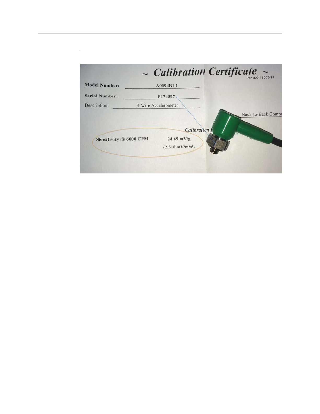
Configure the AMS 9420 Reference Manual
September 2020 MHM-97408
Figure 3-3: Calibration certificate
54 MHM-97408, Rev 22

Reference Manual Configure the AMS 9420
MHM-97408 September 2020
3.1.5 Measurement parameter units
Table 3-3 shows the measurement parameters and available units that can be configured
for each parameter.
Table 3-3: Measurement parameter units
Parameter Units
Velocity (Overall 1, Overall 2)
PeakVue maximum value (PeakVue 1, PeakVue 2)
Temperature (Temperature 2, Ambient)
Sensor Bias (Bias 1, Bias 2) V
Supply Voltage V
3.1.6 Alert levels
The AMS 9420 sets HART status bits to indicate when measured values exceed the
configured thresholds. Each measured value has three levels: Advisory, Maintenance, and
Failed that can be set independently. These thresholds are pre-configured at the factory to
reasonable generic values for single-stage, electric motor-driven equipment trains
operating at 1200–3600 RPM.
The level at which these thresholds should be set depends on the type of equipment being
monitored and on your specific process.
One rule of thumb for vibration is to examine the current level at which the equipment is
operating. Assuming the equipment is in good working condition, set the Advisory level at
2x the current value (or at a minimum of 0.05 in/s RMS, whichever is greater), set the
Maintenance level at 4x the current value, and set the Failed level at 8x the current value.
For example, if the current value for Overall Velocity is 0.1 in/s, set the Advisory threshold
at 0.2 in/s, the Maintenance threshold at 0.4 in/s and the Failed threshold at 0.8 in/s. While
this type of vibration program is not recommended, it can provide a starting point when
no other information is available.
mm/s RMS
in/s RMS
2
m/s
g’s
°C
°F
Table 3-4: Default alert thresholds for vibration
Advise Maintenance Failed
Alert limits
Overall velocity
(sensor 1, 2)
PeakVue
(sensor 1, 2)
Sensor
temperature
MHM-97408, Rev 22 55
Default value
0.14 in/sec
3.556 mm/s
6 g's
58.8399 m/s
65°C
149°F
notification
2
Report
Yes
Yes
Yes
Default value
0.35 in/sec
8.89 mm/s
10 g's
98.0665 m/s
75°C
167°F
notification
2
Report
Yes
Yes
Yes
Default value
1 in/sec
25.4 mm/s
15 g's
147.09975 m/s
85°C
185°F
notification
2
Report
Yes
Yes
Yes

Configure the AMS 9420 Reference Manual
September 2020 MHM-97408
Table 3-4: Default alert thresholds for vibration
Advise Maintenance Failed
Alert limits
Bias
(sensor 1, 2)
Ambient
temperature
Supply voltage <6.0 V No <5.7 V Yes <5.3 V* Yes
*These are read-only parameters and cannot be modified.
Default value
– – – –
– – – –
Report
notification
(continued)
Default value
Report
notification
Default value
Above: >3V
Below: <2V
Above: 85°C
(185°F)*
Below: -40°C
(-40°F)*
Report
notification
Yes*
Yes*
A good rule of thumb for establishing the PeakVue alert levels is to use the rule of 10's. This
applies for most rolling element bearing equipment with a turning speed between 900
and 4000 CPM. Using this approach, the Advisory alert would be set at 10 g's, the
Maintenance alert at 20 g's, and the Failed alert at 40 g's. In general, PeakVue alert levels
can then be interpreted as follows:
10 g's Indication of Abnormal Situation
20 g's Serious Abnormal Situation - Maintenance Plan Required
40 g's Critical Abnormal Situation - Implement Maintenance Plan
For more information on PeakVue, see PeakVue.
The default alert thresholds for temperature correspond closely to a generic open dripproof (ODP) motor with class F insulation and a service factor of 1.15, operating at an
ambient temperature of 40°C or below and at an altitude of 1000 meters or below . These
values are also reasonable thresholds to use when there is no knowledge of the process,
the type of machinery, or the operating environment. For more information, see Overall
Velocity, PeakVue, and temperature.
Table 3-5: Default alert thresholds for temperature
Parameter
Temperature
Advisory Maintenance Failed
Level Enabled Level Enabled Level Enabled
149°F
(65°C)
Yes
167°F
(75°C)
Yes
185°F
(85°C)
Yes
The configurable device alerts include accelerometer bias and supply voltage. The default
settings for these alerts are shown in Table 3-6.
56 MHM-97408, Rev 22

Reference Manual Configure the AMS 9420
MHM-97408 September 2020
Table 3-6: Default levels for configurable device alerts
Parameter
Accelerometer
Bias
Supply Voltage < 6.0 V No < 5.7 V Yes < 5.3 V Yes
Advisory Maintenance Failed
Level Enabled Level Enabled Level Enabled
N/A N/A N/A N/A < 2 V or > 3 V Yes
Notes
• The supply voltage measurement is made under load conditions. The supply voltage
may read differently with the AMS 9420 versus other Emerson transmitters or
multimeters.
• Prior to sensor connection, it is normal to see alerts related to bias failure. These alerts
go away when the sensor is installed correctly.
• When any measured process parameter (Velocity, PeakVue, or Temperature) exceeds
the configured Advisory, Maintenance, or Failed threshold, this causes an “Advisory”
indication that you can view from AMS Device Manager (or in another graphical host).
This indicator itself does not set a status bit.
3.1.7 Publishing mode
The AMS 9420 can publish in either of two modes: optimized or generic (default).
Optimized mode uses less power by combining a large amount of information into a single
command. In this mode, only the four standard process variables (PV, SV, TV, and QV) are
published at the specified update interval and cached in the Smart Wireless Gateway.
When values are cached in the gateway, it is not necessary to wake the device for the host
system to be able to read the variables. The other variables are still available, but any
request to read one of them wakes the device and consumes power.
Generic mode publishes all the process variables the device can produce. This mode
requires three publish messages, which requires approximately 5% more power.
If you are only trending measurements mapped to PV, SV, TV, and QV, use optimized
mode. If you are trending additional variables, use generic mode.
The following table shows a typical mapping example and what is included in optimized
mode and generic mode.
MHM-97408, Rev 22 57

Configure the AMS 9420 Reference Manual
September 2020 MHM-97408
Table 3-7: Typical mapping example showing optimized and generic mode
Parameter Value Type Metric Units Emerson
Process
Variables
Device
Variables
Other Status Bits (including
Overall Velocity 1 Real Number mm/s • •
PeakVue 1 Real Number g's • •
Overall Velocity 2 Real Number mm/s • •
PeakVue 2 Real Number g's • •
Sensor Bias 1 Real Number V •
Sensor Bias 2 Real Number V •
Supply Voltage Real Number V •
Ambient Temperature Real Number °C •
Device_Malfunction)
3.1.8 Update rate
The default update rate is 60 minutes. This is the maximum (fastest) recommended
update rate. You can change this at commissioning or at any time through AMS Device
Manager, a Field Communicator, or the Smart Wireless gateway web server. You can set
the update rate from 1 minute to 1 hour.
Note
If the device uses a power module, and is configured to publish at the fastest allowable
update rate (once per minute), the power module is expected to last only about 2-3
months.
For faster update rates, if your application allows it, use an external DC power option.
Generic Burst
Optimized Mode
Bit (i.e. 0 or 1) None • •
Mode
3.1.9 Minimize power consumption
The primary way to minimize power consumption is to reduce the publish rate.
Two other configuration settings that affect power consumption are:
• LCD (Liquid Crystal Display)
• PowerSave mode
LCD
Disable the LCD after installation is complete if it is not required during normal operation.
It is neither necessary nor sufficient to physically remove the LCD; it must be disabled
through configuration in order to save power. From AMS Device Manager, select the
wireless network where the transmitter is connected, right-click the transmitter and select
Configure → Manual Setup → General Settings tab → LCD Mode → Off.
Note
Disabling the LCD (not removing it, just disabling it) through configuration provides power
savings of about 15–20%.
58 MHM-97408, Rev 22

Reference Manual Configure the AMS 9420
MHM-97408 September 2020
Leave the LCD installed even if it is disabled to provide valuable diagnostic information.
When in a safe location, you can view the LCD by removing the front cover and pressing
the DIAG button. This wakes the device and displays current information. This can be
beneficial for taking a quick reading and to aid in troubleshooting.
WARNING
Do not remove the front electronics end cap or LCD cover while the device is in a
hazardous area.
Removing the cap while the device is in a hazardous area could cause an explosion which
could result in death or serious injury.
CAUTION
The front electronics end cap or LCD cover is certified for hazardous areas in appropriate
gas environments (check the nameplate on the device for details).
Exposing the electronics to a production environment may allow particulates, moisture,
and other airborne chemicals to enter into the device, which could lead to contamination
and potential product performance issues. In all cases, whenever opening the front end
cap, be sure to seal it completely afterwards by tightening until the black O-ring is no
longer visible. For an illustration on how to properly seal the end cap, see Figure 2-23.
PowerSave mode
PowerSave mode is available in AMS 9420 devices that are Rev. 3 or later and it enables the
device to make measurements less frequently, thereby conserving power. This is ideal
when either power module life is more critical than the acquisition rate or when changes in
vibration are only expected to occur over extended periods of time.
You can configure the settings for the PowerSave mode in AMS Machinery Manager (MHM
Access Control must first be enabled) and in AMS Device Manager. The specific field is
referred to as PowerSave Skip Multiplier. It is the number of times the transmitter skips
data acquisitions between updates to the gateway.
At any point, the effective acquisition rate for the AMS 9420 is defined as:
Effective Acquisition Rate = (Update Rate) x (PowerSave Skip Multiplier)
Valid settings for the PowerSave Skip Multiplier range from 1X to 24X. In order to extend
power module life, it should only be combined with a long update rate such as 60 minutes
(54 minutes may be optimal for older versions of the AMS 9420). When this value is set to
1X, the AMS 9420 acquires a new reading at the update rate. A PowerSave Skip Multiplier
of 2X combined with a 60-minute update rate results in a new acquisition every 120
minutes (every two hours). Similarly, a PowerSave Skip Multiplier of 24X with a 60-minute
update rate results in a new acquisition every 1440 minutes (once per day).
3.1.10 Trend parameters
You can trend parameters in multiple locations such as in a plant historian or in AMS
Machinery Manager. The method for configuring this functionality is contained in the
associated software and the details of all the possibilities are beyond the scope of this
MHM-97408, Rev 22 59

Configure the AMS 9420 Reference Manual
September 2020 MHM-97408
manual. This manual only indicates some of the general capabilities and version
requirements.
You can trend values in essentially any host that accepts Modbus or OPC inputs. Configure
OPC tags and Modbus registers for wireless devices in the Smart Wireless Gateway web
interface. Refer to the Smart Wireless Gateway User Manual for additional information.
The settings in the gateway and the host must be consistent and entered in both locations
(for example, Modbus register definitions).
DeltaV integrates native wireless I/O devices on the control network. Refer to the DeltaV
documentation for more information on the required version. You can manage wireless
devices as native HART devices, and trend variables accordingly. This type of installation
also allows richer alerting and diagnostics because the full HART capabilities are available.
Ovation 3.3 or later also integrates the Smart Wireless Gateway with all the associated
benefits of HART.
AMS Machinery Manager 5.4 or later supports HART functionality to read configuration
and alert information, as well as the dynamic parameters from the AMS 9420. This allows
AMS Machinery Manager to auto-discover all of the devices on the wireless mesh as well as
the specific sensor configurations, units settings, and variable mappings for AMS 9420
devices.
Also, with AMS Machinery Manager and AMS 9420 devices (that are licensed for the
Advanced Diagnostics application), you can trend Energy Band parameters and collect
spectrum and waveform information. For more information, see Advanced Diagnostics
application.
DeltaV versions prior to 10.3 and Ovation versions prior to 3.3, though not integrated
through HART, accept Modbus values from the wireless devices. DeltaV also accepts OPC
values.
3.1.11 Remove the power module
The AMS 9420 is powered whenever the power module is installed. To avoid depleting the
power module, remove it when the device is not in use. If you have configured the sensor
and network but are not ready to commission the device, remove the power module to
extend operating life.
Procedure
1. Disconnect the communication leads.
2. Remove the power module.
3.
Replace the transmitter cover.
3.2 Configuration with a Field Communicator
You can configure the AMS 9420 using a 475 Field Communicator. Follow the connection
diagram in Figure 3-2. For instructions on using the AMS Trex™ Device Communicator,
refer to the AMS Trex Device Communicator User Guide.
A Rev 4 DD is recommended when using a 475 Field Communicator to configure the AMS
9420. The DD for the AMS 9420 is located on the DVD that came with the transmitter.
Refer to the Field Communicator User’s Manual for more details on DDs or go to http://
60 MHM-97408, Rev 22

Reference Manual Configure the AMS 9420
MHM-97408 September 2020
www.emerson.com/en-us/catalog/ams-475-field-communicator for instructions on
adding a DD for AMS 9420.
The AMS 9420 requires 475 Field Communicator System Software version 3.2 or later.
3.2.1 Field Communicator menu trees
Figure 3-4 through Figure 3-15 show the 475 Field Communicator configuration menu
trees for AMS 9420 using a Rev 4 DD. For ease of operation, you can access some common
tasks in several locations of the menu structure.
MHM-97408, Rev 22 61

Configure the AMS 9420 Reference Manual
September 2020 MHM-97408
Figure 3-4: Field Communicator menu tree for AMS 9420, one accelerometer: 1 of 4
62 MHM-97408, Rev 22

Reference Manual Configure the AMS 9420
MHM-97408 September 2020
Figure 3-5: Field Communicator menu tree for AMS 9420, one accelerometer: 2 of 4
MHM-97408, Rev 22 63

Configure the AMS 9420 Reference Manual
September 2020 MHM-97408
Figure 3-6: Field Communicator menu tree for AMS 9420, one accelerometer: 3 of 4
64 MHM-97408, Rev 22
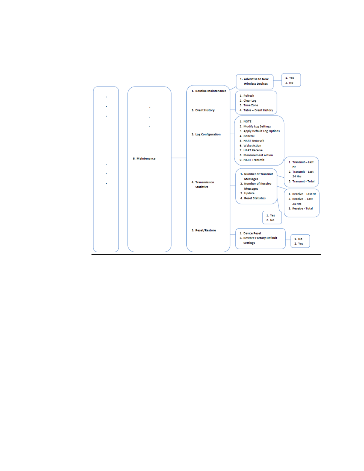
Reference Manual Configure the AMS 9420
MHM-97408 September 2020
Figure 3-7: Field Communicator menu tree for AMS 9420, one accelerometer: 4 of 4
MHM-97408, Rev 22 65

Configure the AMS 9420 Reference Manual
September 2020 MHM-97408
Figure 3-8: Field Communicator menu tree for AMS 9420, one accelerometer with
temperature: 1 of 4
66 MHM-97408, Rev 22

Reference Manual Configure the AMS 9420
MHM-97408 September 2020
Figure 3-9: Field Communicator menu tree for AMS 9420, one accelerometer with
temperature: 2 of 4
MHM-97408, Rev 22 67
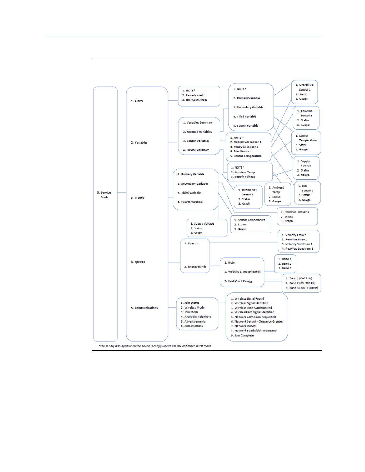
Configure the AMS 9420 Reference Manual
September 2020 MHM-97408
Figure 3-10: Field Communicator menu tree for AMS 9420, one accelerometer with
temperature: 3 of 4
68 MHM-97408, Rev 22
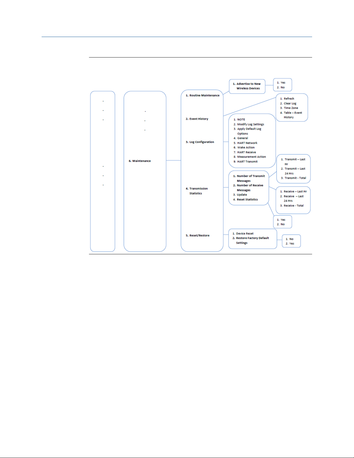
Reference Manual Configure the AMS 9420
MHM-97408 September 2020
Figure 3-11: Field Communicator menu tree for AMS 9420, one accelerometer with
temperature: 4 of 4
MHM-97408, Rev 22 69

Configure the AMS 9420 Reference Manual
September 2020 MHM-97408
Figure 3-12: Field Communicator menu tree for AMS 9420, two accelerometers: 1 of 4
70 MHM-97408, Rev 22
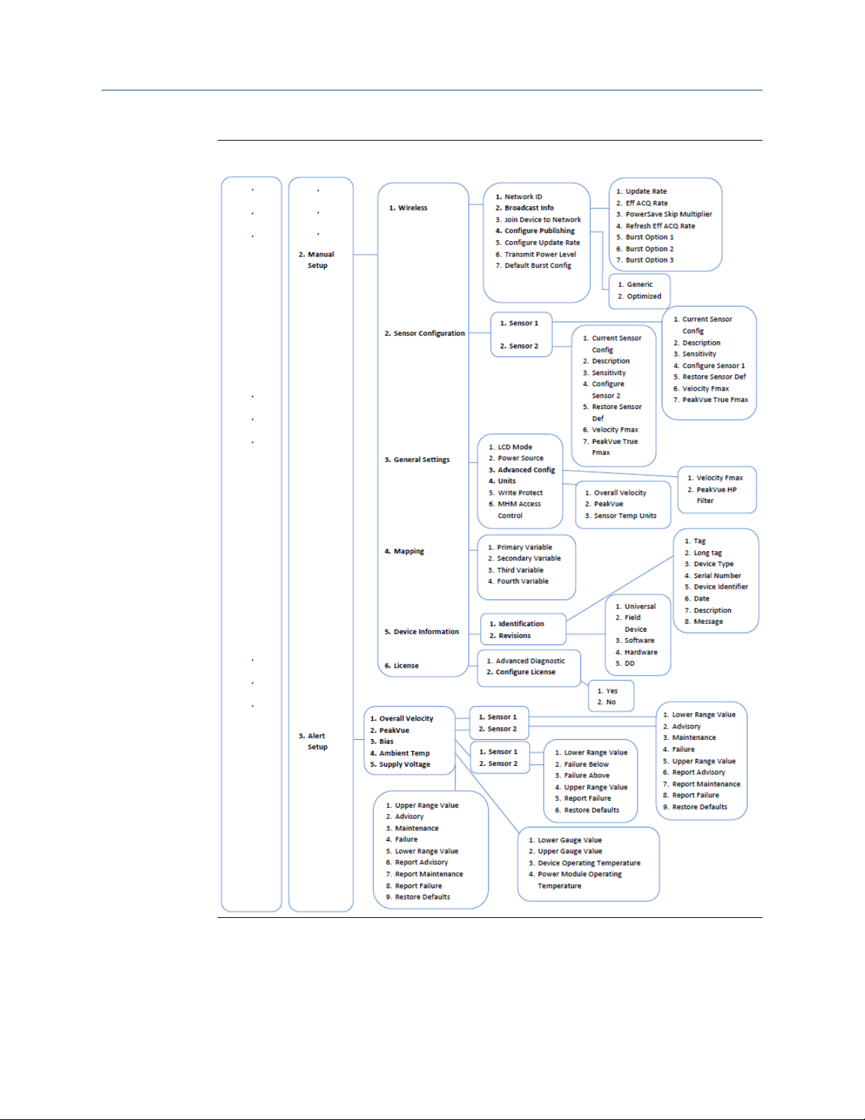
Reference Manual Configure the AMS 9420
MHM-97408 September 2020
Figure 3-13: Field Communicator menu tree for AMS 9420, two accelerometers: 2 of 4
MHM-97408, Rev 22 71
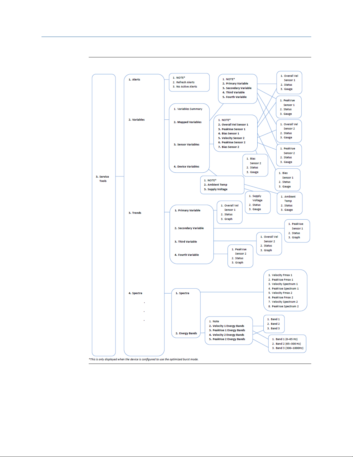
Configure the AMS 9420 Reference Manual
September 2020 MHM-97408
Figure 3-14: Field Communicator menu tree for AMS 9420, two accelerometers: 3 of 4
72 MHM-97408, Rev 22
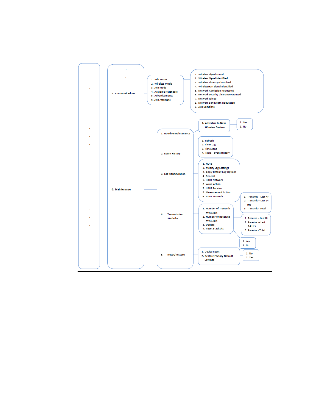
Reference Manual Configure the AMS 9420
MHM-97408 September 2020
Figure 3-15: Field Communicator menu tree for AMS 9420, two accelerometers: 4 of 4
MHM-97408, Rev 22 73

Configure the AMS 9420 Reference Manual
September 2020 MHM-97408
3.2.2 Field Communicator fast key sequences
Note
The following fast key sequences assume that you are using the 475 Field Communicator
with a Rev 4 DD. Press Send to save the changes to the device.
Table 3-8: AMS 9420 network configuration
Key sequence Menu items
Network ID
Broadcast Info
2, 2, 1
(Manual Setup)
2, 1
(Guided Setup)
Join Device to Network
Configure Publishing
Configure Update Rate
Transmit Power Level
Default Burst Config
Configure Sensors
Configure Variable Mapping
Configure Units
Alert Limits
Sensor Power Enable
Join Device to Network
Configure Publishing
Configure Update Rate
Table 3-9: AMS 9420 common fast key sequences
Function Key sequence Menu items
LCD Mode
Power Source
General settings 2, 2, 3 (Manual Setup)
Alert setup 2, 3
Update rate
Publishing mode
Write protect 2, 2, 3, 5 (Manual Setup) Write Protect
2, 1, 8 (Guided Setup)
2, 2, 1, 5 (Manual Setup)
2, 1, 7 (Guided Setup)
2, 2, 1, 4 (Manual Setup)
Advanced Config
Units
Write Protect
MHM Access Control
Overall Velocity
PeakVue
Bias
Ambient Temperature
Supply Voltage
Configure Update Rate
Configure Publishing
74 MHM-97408, Rev 22

Reference Manual Configure the AMS 9420
MHM-97408 September 2020
Table 3-9: AMS 9420 common fast key sequences
Function Key sequence Menu items
Power options 2, 2, 3, 2 (Manual Setup) Power Source
MHM Access Control 2, 2, 3, 6 (Manual Setup) MHM Access Control
Supply power to sensor 2, 1, 5 (Guided Setup) Sensor Power Enable
Configure variable mapping 2, 1, 2 (Guided Setup) Configure Variable Mapping
Device reset 3, 6, 5
(continued)
Device Reset
Restore Factory Default Settings
MHM-97408, Rev 22 75

Configure the AMS 9420 Reference Manual
September 2020 MHM-97408
3.3 Configuration with AMS Device Manager
3.3.1 Configure wireless network credentials in AMS Device Manager
Prerequisites
Before performing operations in AMS Device Manager, first scan the AMS 9420 with a
wired HART modem. Right-click the HART Modem icon
Scan All Devices.
Note
Configuring the wireless network is only applicable using a wired HART modem and
cannot be done using WirelessHART devices.
Procedure
in Device Explorer and select
1. Right-click the AMS 9420 device and select Methods
2. Enter the network ID for the wireless network in the Join Device to Network screen
and click Next.
You can obtain the network ID from the Smart Wireless Gateway web server. Click
Setup → Network → Settings.
3. Enter the Join Key in the screens that follow, and click Next.
4. Select the Accept new join key option, and click Next.
5. Click Finish when done.
→ Join Network.
76 MHM-97408, Rev 22

Reference Manual Configure the AMS 9420
MHM-97408 September 2020
3.3.2 Right-click menu
The right-click menu of the AMS 9420 device in AMS Device Manager provides a quick link
to the Configure, Compare, Service Tools, and Overview windows, as well as to other
context menus available for the device. This document only discusses the Overview,
Configure, and Service Tools windows; for more information on the other context menus,
refer to AMS Device Manager Books Online.
In the Device Explorer view, select the wireless network where the transmitter is
connected and right-click the transmitter to display the context menus.
Figure 3-16: AMS 9420 right-click menu
MHM-97408, Rev 22 77

Configure the AMS 9420 Reference Manual
September 2020 MHM-97408
Overview
Figure 3-17: Overview window
The Overview window provides a glimpse of the status of the CSI 9420, including the
primary purpose variables associated with it.
You can also access the following shortcuts from this page:
• Device Information
• Configure Sensors
• Join Device to Network
• Acquire New Measurement
78 MHM-97408, Rev 22

Reference Manual Configure the AMS 9420
MHM-97408 September 2020
Device Information
From the Overview window, click Device Information to display relevant device
information.
Figure 3-18: Device Information window
Click the Identification tab to display the device tag, long tag, device type, serial number,
identifier, and description.
Click the Revisions tab to display the universal, field device, software, hardware, and DD
revision numbers.
Click the Radio tab to display the device MAC address, manufacturer, device type, revision
numbers, and transmit power level.
Click the Security tab to display Write Protect information and to view whether MHM
Access Control is enabled.
Click the License tab to display installed licensable features such as the Advanced
Diagnostics application.
Click License tab → Configure License to configure/change installed licenses.
MHM-97408, Rev 22 79
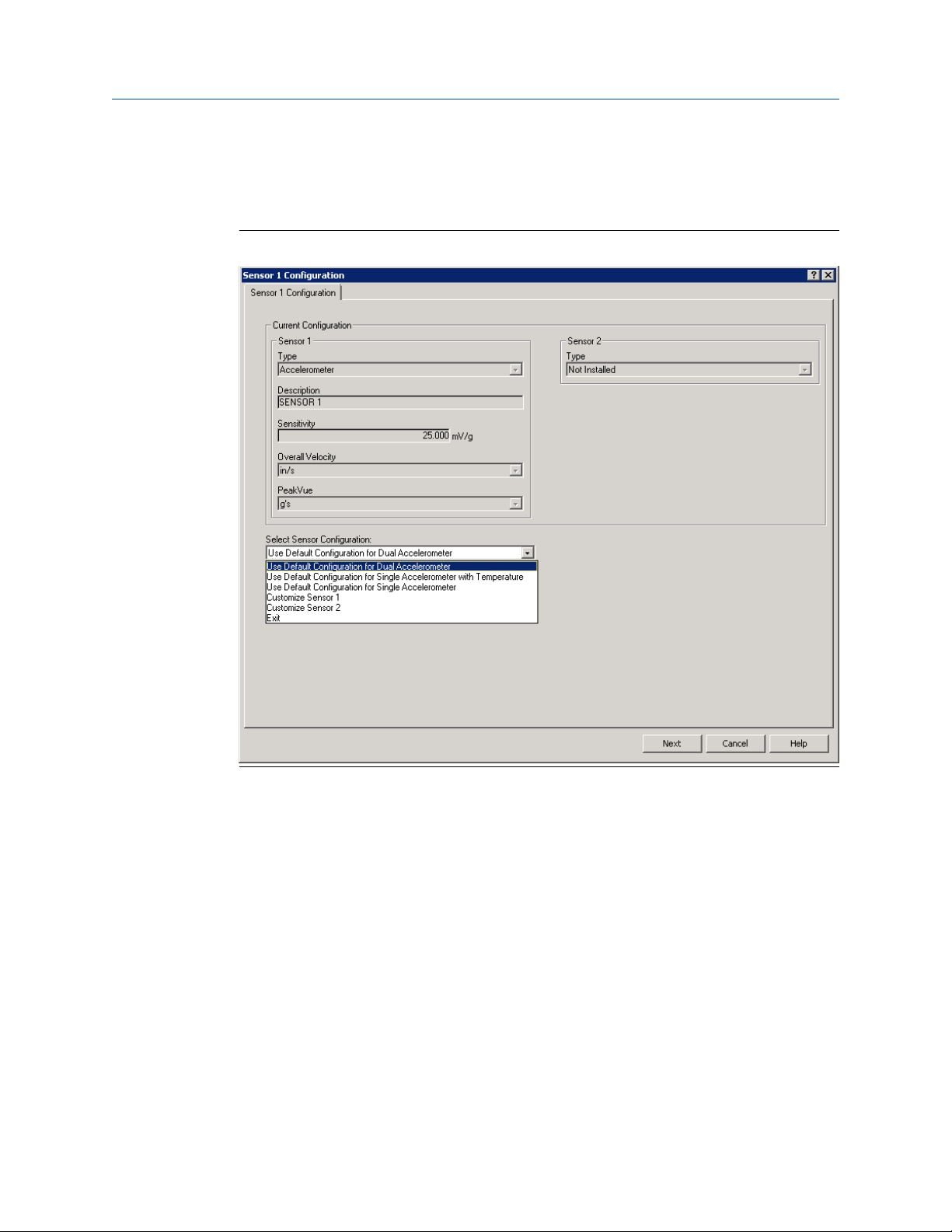
Configure the AMS 9420 Reference Manual
September 2020 MHM-97408
Configure Sensors
From the Overview window, click Configure Sensors to display installed sensors and
current sensor configurations.
Figure 3-19: Sensor Configuration window
Click the Select Sensor Configuration drop-down to select a sensor configuration to apply
to the installed sensors.
80 MHM-97408, Rev 22

Reference Manual Configure the AMS 9420
MHM-97408 September 2020
Join Device to Network
From the Overview window, click Join Device to Network to enter network identifiers and
join keys that will enable the transmitter to join a wireless network.
Figure 3-20: Join Device to Network window
MHM-97408, Rev 22 81
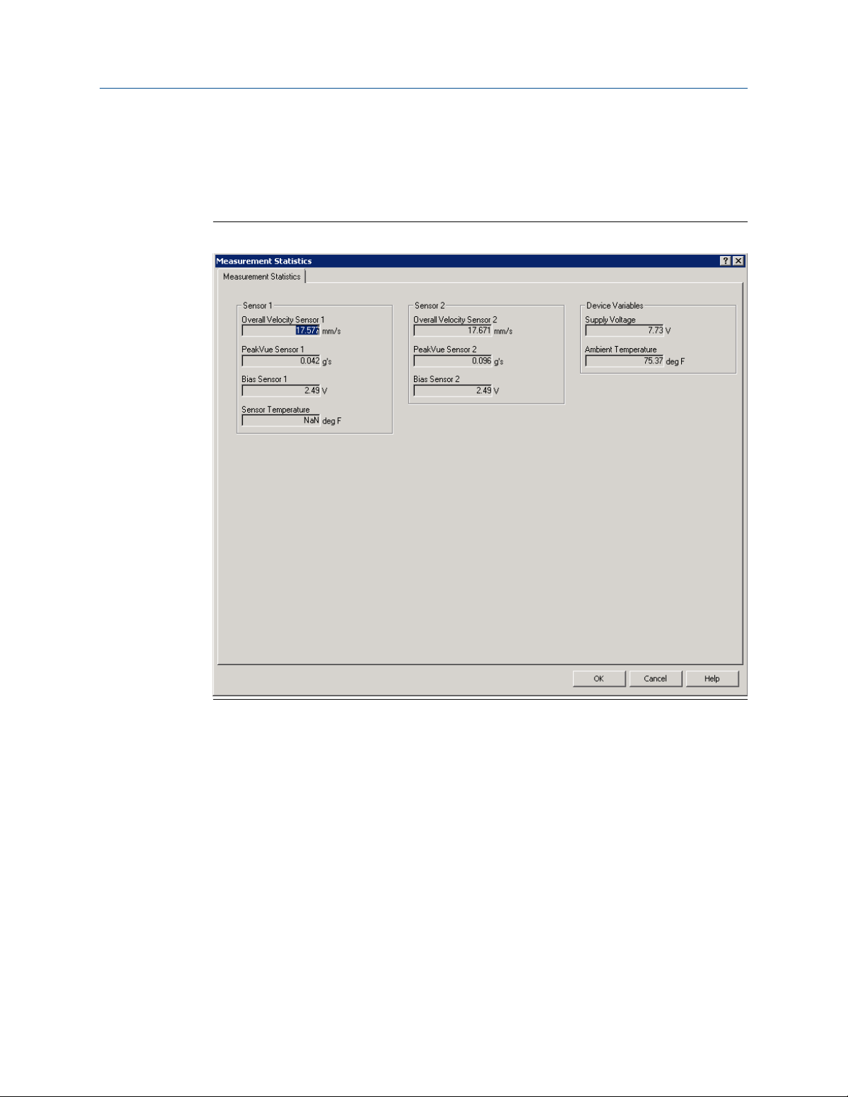
Configure the AMS 9420 Reference Manual
September 2020 MHM-97408
Acquire New Measurement
From the Overview window, click Acquire New Measurement to display measurement
statistics for Velocity, PeakVue, bias, and sensor temperature for installed sensors. This
also displays supply voltage and ambient temperature information for the transmitter.
Figure 3-21: Measurement Statistics window
82 MHM-97408, Rev 22
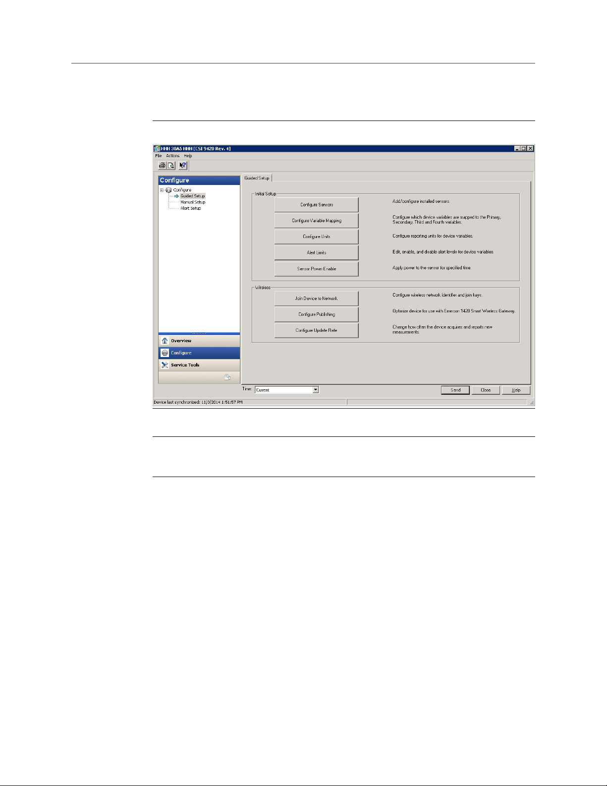
Reference Manual Configure the AMS 9420
MHM-97408 September 2020
Configure
Figure 3-22: Configure window
The Configure window lets you configure device settings.
Important
To be able to edit configuration settings, select Current in the Time drop-down menu at
the bottom of the screen.
MHM-97408, Rev 22 83

Configure the AMS 9420 Reference Manual
September 2020 MHM-97408
Guided Setup
Guided Setup lets you configure device settings in a guided step-by-step process.
Click Configure Sensors to display or configure installed sensors.
Click Configure Variable Mapping to display or specify which measurements are reported
as the Primary, Secondary, Third, and Fourth variables.
Click Configure Units to configure units for Overall Velocity, PeakVue, and temperature.
Click Alert Limits to define the lower range and upper range values and alert limits for
Advisory, Maintenance, and Failure for each of the process variables. You can also
configure alert reporting from here.
Click Sensor Power Enable to supply power to the sensor for a specific amount of time.
Note
Sensor Power Enable is only available when the device is connected to AMS Device
Manager using a USB or serial HART modem and when the device is connected to a Field
Communicator. This feature is not available when the device is connected to AMS Device
Manager using a WirelessHART connection.
Click Join Device to Network to enter network identifiers and join keys that will enable the
transmitter to join a wireless network.
Click Configure Publishing to set how parameters are published (generic or optimized).
Click Configure Update Rate to set how often the device acquires and reports new
measurements (update rate) and to specify the number of times the transmitter skips data
acquisitions between updates to the gateway (PowerSave Skip Multiplier).
84 MHM-97408, Rev 22
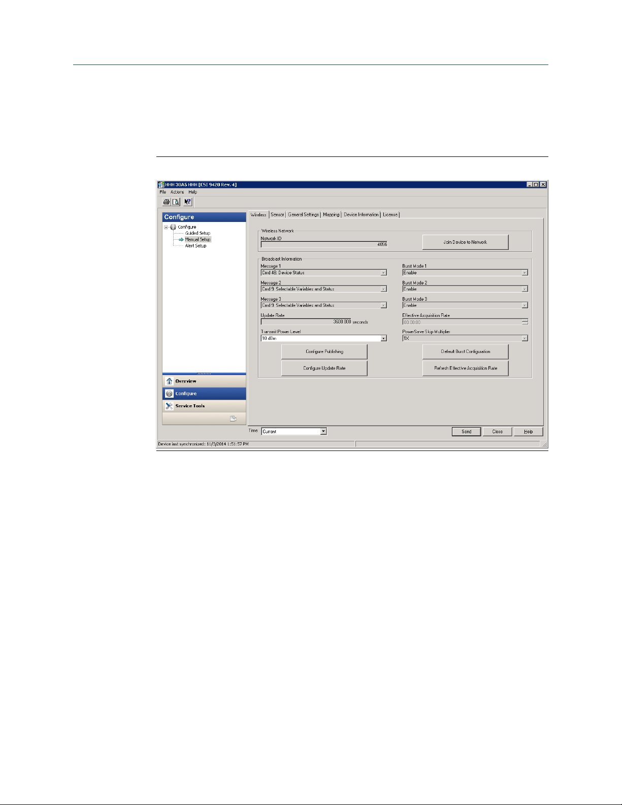
Reference Manual Configure the AMS 9420
MHM-97408 September 2020
Manual Setup
Manual Setup lets you configure device settings manually.
Click the Wireless tab to display wireless network information for the transmitter.
Figure 3-23: Wireless tab
Click Join Device to Network to enter network identifiers and join keys that will enable the
transmitter to join a wireless network.
Click Configure Publishing to set how parameters are published (generic or optimized).
Click Configure Update Rate to set how often the device acquires and reports new
measurements (update rate) and to specify the number of times the transmitter skips data
acquisitions between updates to the gateway (PowerSave Skip Multiplier).
Click Default Burst Configuration to reset the burst configuration to default values.
Click Refresh Effective Acquisition Rate to refresh the value in the Effective Acquisition
Rate field.
Click the Sensor tab to display current sensor configurations. You can also edit the sensor
sensitivity value from this page.
MHM-97408, Rev 22 85
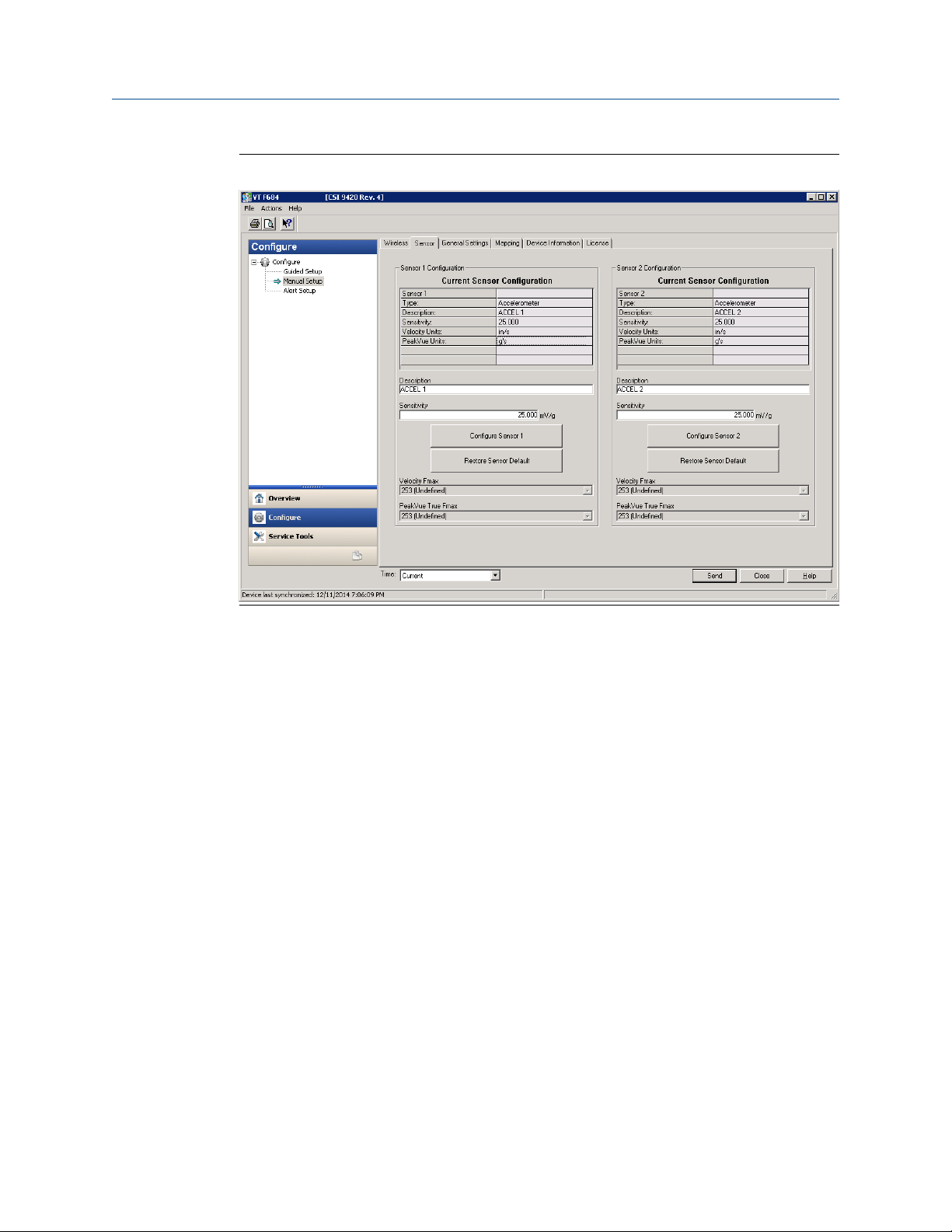
Configure the AMS 9420 Reference Manual
September 2020 MHM-97408
Figure 3-24: Sensor tab
Click Configure Sensor x to configure the parameters for the specific sensor.
Click Restore Sensor Default to reset the sensor parameters to default values.
Click the General Settings tab to display or edit general transmitter settings.
86 MHM-97408, Rev 22
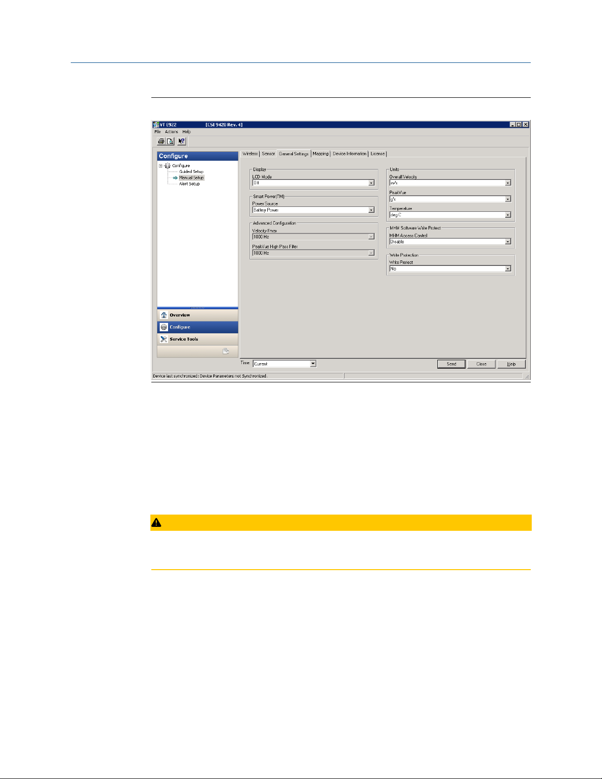
Reference Manual Configure the AMS 9420
MHM-97408 September 2020
Figure 3-25: General Settings tab
Click the LCD Mode drop-down to enable or disable the LCD, or to set it to
troubleshooting mode.
Click the Power Source drop-down to select the transmitter power source.
Select the units for measurement variables from the Overall Velocity, PeakVue, and
Temperature drop-down menus.
Click the MHM Access Control drop-down to enable or disable Access Control for AMS
Machinery Manager. Access Control allows AMS Machinery Manager to make changes to
the AMS 9420 configuration.
CAUTION
If the device will be commissioned in a HART DCS host (e.g., DeltaV or Ovation), do not
enable AMS Machinery Manager to make changes to the configuration.
Click the Write Protect drop-down to specify whether variables can be written to the
device.
Click the Mapping tab to specify which measurements are reported as the Primary,
Secondary, Third, and Fourth variables.
MHM-97408, Rev 22 87
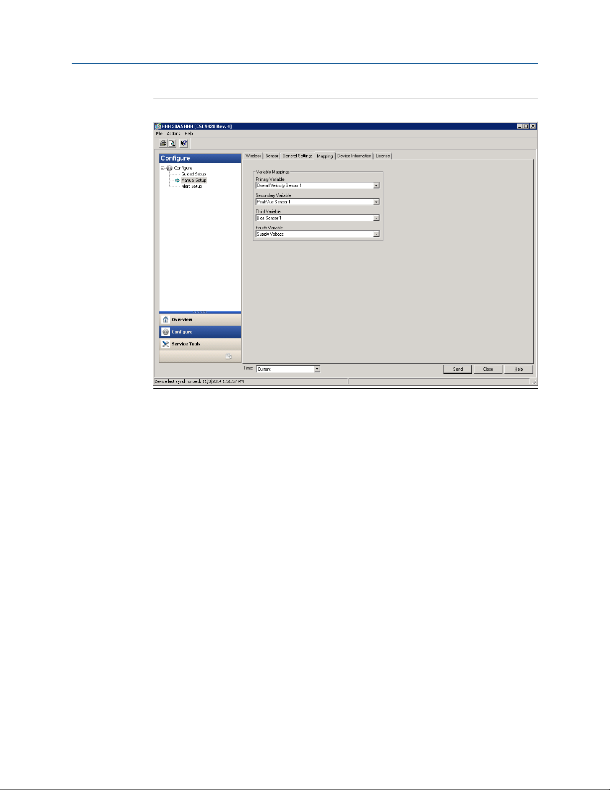
Configure the AMS 9420 Reference Manual
September 2020 MHM-97408
Figure 3-26: Mapping tab
Click the Device Information tab to display the device tag, long tag, device type, serial
number, device identifier, and description, and to display the universal, field device,
software, hardware, and DD revision numbers.
88 MHM-97408, Rev 22

Reference Manual Configure the AMS 9420
MHM-97408 September 2020
Figure 3-27: Device Information tab
MHM-97408, Rev 22 89

Configure the AMS 9420 Reference Manual
September 2020 MHM-97408
License tab
Click the License tab to display installed licensable features such as the Advanced
Diagnostics application.
Figure 3-28: License tab
Click Configure License to configure/change installed licenses.
90 MHM-97408, Rev 22

Reference Manual Configure the AMS 9420
MHM-97408 September 2020
Alert Setup
Alert Setup lets you configure the upper and lower range values and alarm limits for
Overall Velocity, PeakVue, Bias, Sensor Temperature, Ambient Temperature, and Supply
Voltage.
Figure 3-29: Alert Setup
Click the corresponding sensor/device variable tab and select the Report Advisory, Report
Maintenance, or Report Failure check boxes to generate alarms when actual measured
values exceed the thresholds specified. When these check boxes are not selected, no
alarm is reported.
Click Restore Defaults to restore default alarm thresholds for the selected variable.
MHM-97408, Rev 22 91

Configure the AMS 9420 Reference Manual
September 2020 MHM-97408
Service Tools
Figure 3-30: Service Tools window
The Service Tools window displays alert conditions. These include hardware and software
malfunctions or parameters with values beyond specifications.
Alerts
Click Alerts to display active alerts for the device.
92 MHM-97408, Rev 22

Reference Manual Configure the AMS 9420
MHM-97408 September 2020
Variables
Click Variables to display graphical gauges of sensor and device variables.
Figure 3-31: Variables
Click the Mapped Variables tab to display graphical gauges of variables and their
mappings.
Click the Sensor Variables tab to display graphical gauges of the variables for each
connected sensor.
Click the Device Variables tab to display graphical gauges of ambient temperature and
supply voltage variables.
MHM-97408, Rev 22 93

Configure the AMS 9420 Reference Manual
September 2020 MHM-97408
Trends
Click Trends to display hour-long trends for each of the four measurement variables (PV,
SV, TV, and QV).
Figure 3-32: Trends
Note
The trend plots begin when Trends is selected, and continue to build as long as this
remains selected.
94 MHM-97408, Rev 22

Reference Manual Configure the AMS 9420
MHM-97408 September 2020
Spectra
Click Spectra to display spectral and analysis parameter data and to configure spectral
data acquisition settings. You can import spectral data to AMS Machinery Manager for
further analysis.
Note
You must have the Advanced Diagnostics application license to view this feature. For more
information on the Advanced Diagnostics application, see Advanced Diagnostics
application.
Figure 3-33: Spectra
The Fmax settings define the default frequency range of the thumbnail spectra for Velocity
and PeakVue. If you enable the Average Velocity option in AMS Machinery Manager, you
can configure the high-resolution Velocity Analytical spectrum to return 400 or 800 lines
of resolution, with averaging. If the Average Velocity option is not enabled in AMS
Machinery Manager, the spectrum is calculated at 1600 lines of resolution, with no
averaging.
When vibration data is acquired, a PeakVue waveform is sampled for 3.2 seconds. If you
set the PeakVue True Fmax to 1000 Hz, the first 1.6 seconds of the PeakVue waveform is
used for the analytical spectrum. If you set the Fmax to 500 Hz, the entire 3.2 second
PeakVue waveform is used to calculate the analytical spectrum. Regardless of what you
choose in Fmax, the overall PeakVue trend parameter is calculated over the entire 3.2
second waveform.
Click Velocity Spectrum x and PeakVue Spectrum x to display spectral plots of the latest
acquired data for Velocity and PeakVue for connected sensors.
MHM-97408, Rev 22 95
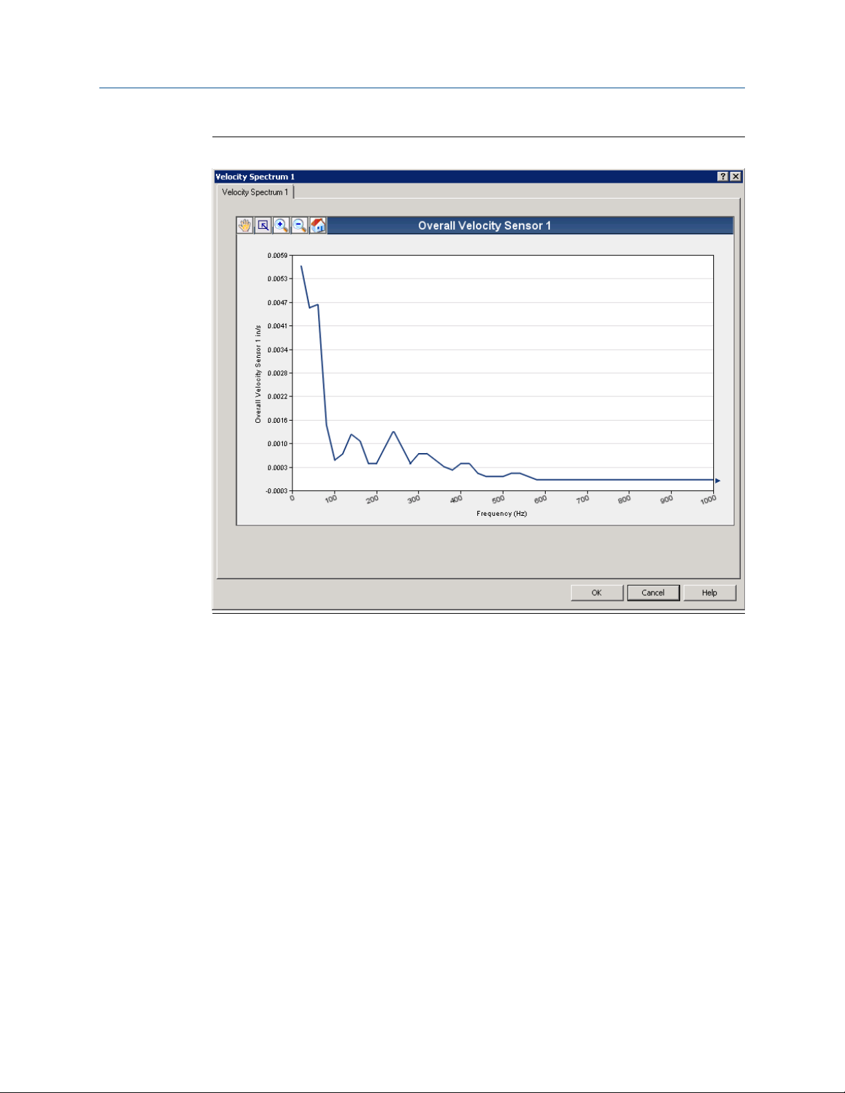
Configure the AMS 9420 Reference Manual
September 2020 MHM-97408
Figure 3-34: Velocity spectrum
96 MHM-97408, Rev 22
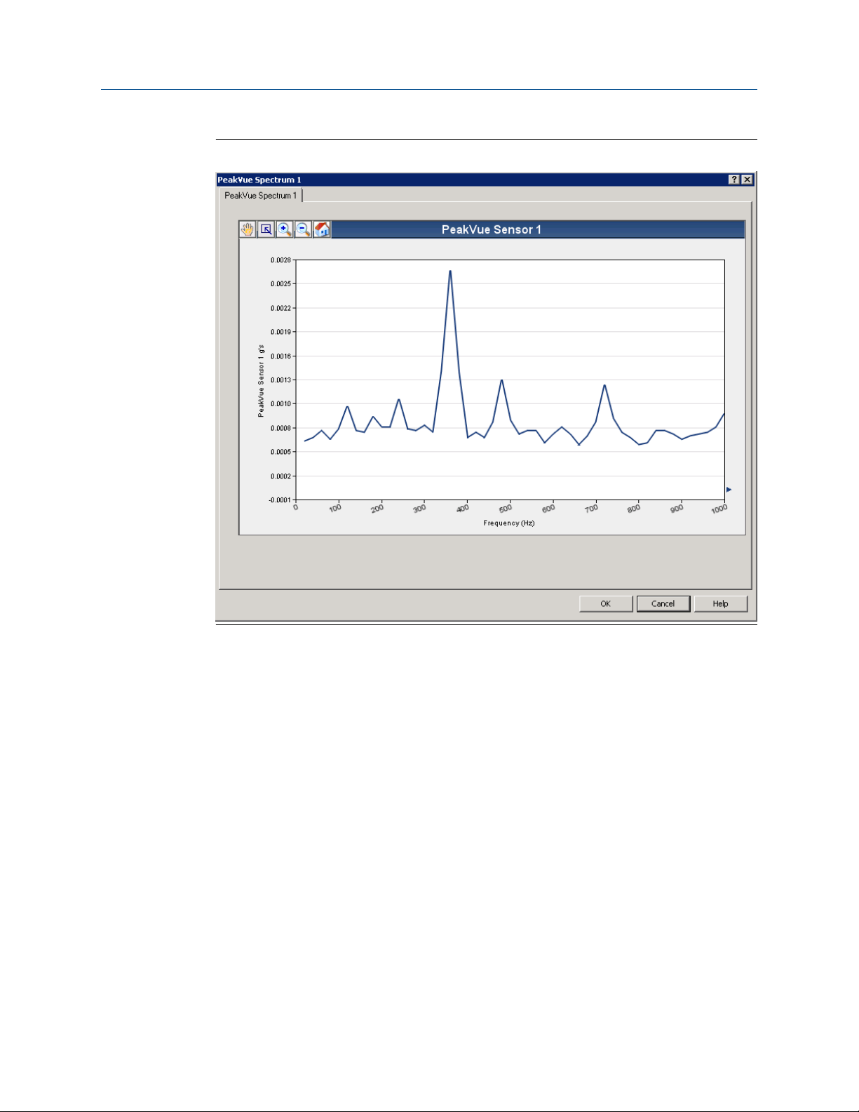
Reference Manual Configure the AMS 9420
MHM-97408 September 2020
Figure 3-35: PeakVue spectrum
Click the Energy Bands tab to display calculated energy band values.
MHM-97408, Rev 22 97
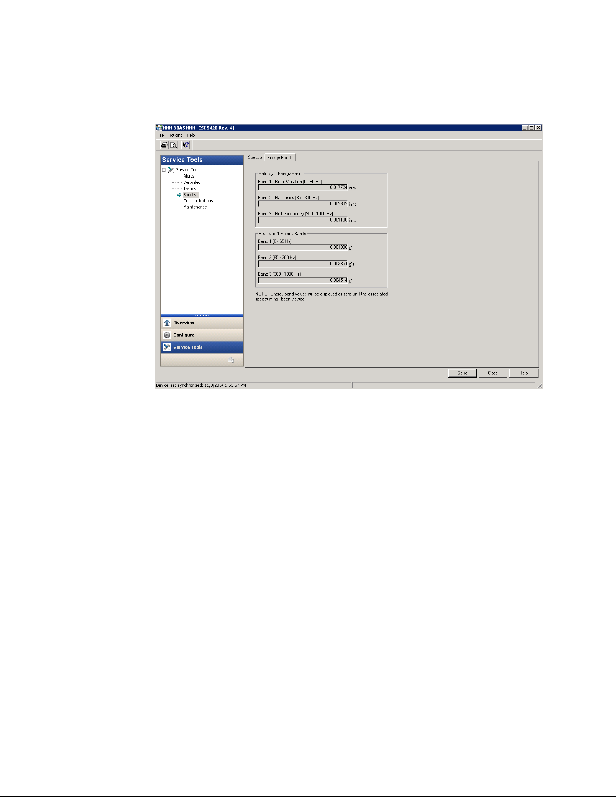
Configure the AMS 9420 Reference Manual
September 2020 MHM-97408
Figure 3-36: Energy Bands tab
98 MHM-97408, Rev 22
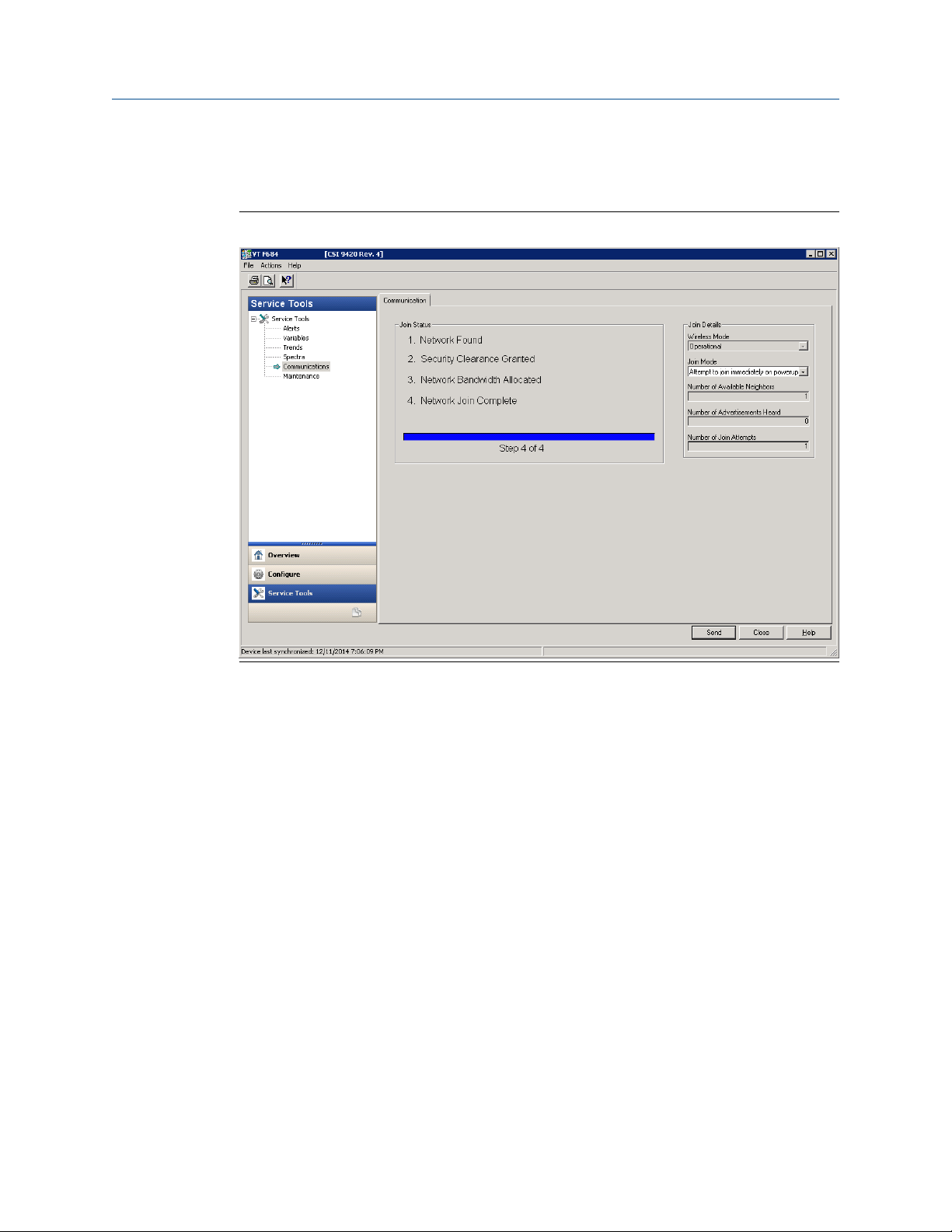
Reference Manual Configure the AMS 9420
MHM-97408 September 2020
Communications
Click Communications to display network join status information.
Figure 3-37: Communications
Click the Join Mode drop-down to select when the transmitter attempts to join a network.
MHM-97408, Rev 22 99

Configure the AMS 9420 Reference Manual
September 2020 MHM-97408
Maintenance
Click Maintenance to manage the device maintenance and log settings.
Figure 3-38: Maintenance
Click Routine Maintenance tab → Advertise to New Wireless Devices to enable the
gateway to search for new wireless devices on the network. This helps new devices join the
network faster.
Click the Event History tab to display transmitter events such as measurements, HART
transmissions, and wake actions.
Click the Log Configuration tab to configure event logging options. Data from event logs
are useful during a debug process.
Click the Transmission Statistics tab to display statistics related to radio transmission
operation such as communication interval between data requests.
Click the Reset/Restore tab to reset the device or to restore factory default settings.
100 MHM-97408, Rev 22
 Loading...